EP3034904A1 - Knitted elastomeric vibratory damping apparatus - Google Patents
Knitted elastomeric vibratory damping apparatus Download PDFInfo
- Publication number
- EP3034904A1 EP3034904A1 EP15198786.4A EP15198786A EP3034904A1 EP 3034904 A1 EP3034904 A1 EP 3034904A1 EP 15198786 A EP15198786 A EP 15198786A EP 3034904 A1 EP3034904 A1 EP 3034904A1
- Authority
- EP
- European Patent Office
- Prior art keywords
- knitted
- mesh
- loops
- damping
- arrangement
- Prior art date
- Legal status (The legal status is an assumption and is not a legal conclusion. Google has not performed a legal analysis and makes no representation as to the accuracy of the status listed.)
- Granted
Links
Images






Classifications
-
- F—MECHANICAL ENGINEERING; LIGHTING; HEATING; WEAPONS; BLASTING
- F16—ENGINEERING ELEMENTS AND UNITS; GENERAL MEASURES FOR PRODUCING AND MAINTAINING EFFECTIVE FUNCTIONING OF MACHINES OR INSTALLATIONS; THERMAL INSULATION IN GENERAL
- F16F—SPRINGS; SHOCK-ABSORBERS; MEANS FOR DAMPING VIBRATION
- F16F7/00—Vibration-dampers; Shock-absorbers
- F16F7/10—Vibration-dampers; Shock-absorbers using inertia effect
- F16F7/104—Vibration-dampers; Shock-absorbers using inertia effect the inertia member being resiliently mounted
- F16F7/108—Vibration-dampers; Shock-absorbers using inertia effect the inertia member being resiliently mounted on plastics springs
-
- D—TEXTILES; PAPER
- D04—BRAIDING; LACE-MAKING; KNITTING; TRIMMINGS; NON-WOVEN FABRICS
- D04B—KNITTING
- D04B1/00—Weft knitting processes for the production of fabrics or articles not dependent on the use of particular machines; Fabrics or articles defined by such processes
- D04B1/14—Other fabrics or articles characterised primarily by the use of particular thread materials
- D04B1/18—Other fabrics or articles characterised primarily by the use of particular thread materials elastic threads
-
- D—TEXTILES; PAPER
- D04—BRAIDING; LACE-MAKING; KNITTING; TRIMMINGS; NON-WOVEN FABRICS
- D04B—KNITTING
- D04B1/00—Weft knitting processes for the production of fabrics or articles not dependent on the use of particular machines; Fabrics or articles defined by such processes
- D04B1/22—Weft knitting processes for the production of fabrics or articles not dependent on the use of particular machines; Fabrics or articles defined by such processes specially adapted for knitting goods of particular configuration
-
- F—MECHANICAL ENGINEERING; LIGHTING; HEATING; WEAPONS; BLASTING
- F16—ENGINEERING ELEMENTS AND UNITS; GENERAL MEASURES FOR PRODUCING AND MAINTAINING EFFECTIVE FUNCTIONING OF MACHINES OR INSTALLATIONS; THERMAL INSULATION IN GENERAL
- F16F—SPRINGS; SHOCK-ABSORBERS; MEANS FOR DAMPING VIBRATION
- F16F1/00—Springs
- F16F1/36—Springs made of rubber or other material having high internal friction, e.g. thermoplastic elastomers
- F16F1/362—Springs made of rubber or other material having high internal friction, e.g. thermoplastic elastomers made of steel wool, compressed hair, woven or non-woven textile, or like materials
Definitions
- This application generally relates to the field of damping of structures and more specifically to a vibratory damping assembly that is configured to overlay or otherwise be disposed in relation to a structure under load, in which the flexible vibratory damping assembly is defined by an elastomeric material made up of a plurality of adjacent loops that are formed in a knitted, weaved, loomed, stitched or crocheted configuration.
- damping assemblies are configured to provide damping of structures against dynamic loads, such as those created by oscillating sources, in order to prevent premature failures.
- damping assemblies can include, for example, various damping elements that are axially disposed in relation to a defined structure or housing. As the load is applied, dynamic reactions within the assembly absorbs energy, thereby damping the applied load.
- a hydraulically controlled damping assembly of this type is described in U.S. Patent No. 3,151,856 , the entire contents of which are herein incorporated by reference.
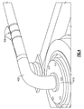
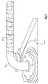
- FIG. 1 and 2 Another version of a vibratory damping apparatus is shown in Figs. 1 and 2 .
- This damping apparatus 700 is described by a bag-like structure 704 formed from at least one sheet of a fluid impermeable material, such as Nomex.
- the structure 704 is defined by a top edge 725, a bottom edge 727, and respective outer edges 731, 735 as well as an optional center seam 715, separating the structure 704 into mirrored sides 708, 712 as well as a plurality of interior cavities 717, 719, 721 in which at least some of the interior cavities are at least partially filled with a granulated damping material.
- a plurality of engagement members 740 provided along the outer edges 731, 735 and more specifically border portions 737 and the flexible nature of the material enable the enclosure 704 to be flexibly wrapped about a physical object, such as a pipe 750. Additional details relating to this latter damping apparatus are provided in U.S. Patent Application Publication No. 2013-0105262A1 , the entire contents of which are herein incorporated by reference.
- a vibratory damping apparatus comprising at least one knitted section or mesh section made from an elastomeric material, the at least one knitted or mesh section being defined by a plurality of adjacent elastomeric loops that are independently influenced by input loads.
- knitted refers to any method for which an elastomeric cord(s) or thread(s) can be assembled to create a series of intertwined loops or layers of construction including but not limited to knitting, crocheting, looming, weaving, stitching and the like.
- the size of the elastomeric cord and adjacent intertwined loops that are formed, as well as the voided density of the created knitted or mesh section(s) and the properties of the elastomeric material, enables a virtually unlimited number of configurations and varied designs in order to effectively tune the damping apparatus for loading conditions/environments that may be encountered.
- a method of manufacturing a vibratory damping apparatus comprising the steps of providing at least one section of at least one elastomeric material and forming a plurality of adjacent individual loops from the at least one elastomeric material into a knitted arrangement.
- these various configurations can be combined and assembled to further influence performance characteristics and benefits.
- the knitted arrangement is defined by using elastomeric thread or cord wherein at least one of the density of the resulting mesh, the elastomeric thread diameter and/or loop size of at least one portion of the knitted arrangement can be suitably configured or varied in order to tune damping characteristics of the apparatus in regard to a structure under load.
- At least one outer layer can be added to at least a portion of the formed knitted arrangement or a mesh section in order to create a constrained layer.
- a method for damping a structure or structural component comprising the steps of providing a sheet-like section defined by a elastomeric material that is formed into a knitted arrangement, the knitted arrangement including a plurality of adjacent loops; and attaching the sheet-like section to a structure or structural component under load wherein the adjacent loops of the knitted arrangement are caused to vibrate independently based upon the load applied
- the sheet-like section can be configured to permit it to be wrapped about a structural component, such as a pipe, or the sheet-like section can be otherwise attached.
- the method can further include the step of applying a rigid or semi-rigid outer layer onto at least a portion of the sheet-like section.
- This layer can be metal, by way of example.
- the herein described damping apparatus is highly flexible and easily conforms thereby enabling the apparatus to be wrapped about or hung from structural components under load without any or significant modification thereto.
- the herein described damping apparatus can be effectively used in conjunction with a varied number of different structures having conventional and/or non-conventional shapes or configurations.
- the herein described damping apparatus is simple in terms of its overall construction and ease of use in that the entire apparatus can be fabricated as a single or unitary lightweight component made from one or several elastomers.
- the herein described apparatus has no moving parts, such as pistons or springs, that can prematurely fail and require replacement of either the damping apparatus and/or the component under load.
- the unitary apparatus is reliant upon the independence of the individual loops and certain additive features based upon contact between adjacent loops of the knitted configuration to achieve desired damping.
- the herein described damping apparatus is capable of absorbing a broad spectrum of input energy and can reliably and effectively provide damping over a broad range of input frequencies.
- the knitted character of the herein described vibratory damping apparatus also enables heat dissipation, for example, when the apparatus is wrapped in overlaying relation or hung from structural components having hot surfaces, such as pipes and the like.
- the terms “comprising”, “comprises”, and “comprise” are open-ended terms definitionally used to transition from a subject recited before the term to one or more elements recited after the term, where the element or elements listed after the term are not necessarily the only elements that make up the subject.
- the term "knitted” refers to a configuration defined by intertwining threads of at least one material into a series of connected loops that can be formed into a two-dimensional pattern.
- This term as used throughout applies to any method for which an elastomeric cord can be assembled to create intertwined loops or layers of construction including but not limited to knitting, crocheting, looming, weaving, stitching and the like.
- elastomer or "elastomeric material” for purposes of this application refers to any natural or synthetic material having the properties of rubber in which the material is permitted to deform under application of a load but in which the material resumes its original shape upon removal of the deforming force or load.
- each depicted vibratory damping apparatus 300A, 300B is commonly defined by threads or cords that are made from an elastomeric material having a defined diameter wherein the material is formed into a knitted arrangement 304A, 304B defined herein by a series of adjacent loops or loop portions 312A, 312B that are configured into a two-dimensional mesh pattern.
- the loops 312A, 312B in each apparatus 300A, 300B are not bonded to one another and are therefore independent in terms of their behavior and the elastic character of the thread material.
- the size of the loops 312A, 312B including the density of the defined mesh as well as the diameter of the thread or cords of the elastomeric material can be varied as depicted, by way of example only, according to Fig. 3 .
- the knitted arrangement in each instance takes on the form of a sheet that can be wrapped directly about a structural component, such as a pipe, and secured thereto using clips, hooks or the like.
- a structural component such as a pipe
- the knitted apparatus 300A, 300B can be hung from a structural component or could be arranged into other shapes, such as, for example, a knitted sleeve or tubular design that is configured to be fitted in overlaying relation onto an object for purposes of damping.
- an outer layer such as a metal tape or other suitably rigid material can be applied onto at least a portion of the knitted arrangement and optionally secured, such as by using adhesives or other attaching means as in the instance of a metal tape.
- the outer layer can be simply placed in overlaying relation onto a portion of the knitted arrangement. In either event and for purposes of damping, the applied outer layer forms a constrained layer boundary, as compared to the highly flexible knitted arrangement provided by the multiple independent loops of elastomeric material.
- an applied load to the structural component causes the adjacent loops of the knitted arrangement to act independently relative to one another, as shown in part according to an apparatus partially shown in section in Fig. 9 . That is, each of the loops 904 of the knitted arrangement is configured to vibrate as shown at 912 in response to an input load independently of the remaining adjacent loops. Therefore, the degree of damping of the apparatus 900 can be controlled such that the knitted loops 904 can achieve resonance at various frequencies, depending, for example, upon the length of the loops.
- the size of the adjacent loops as well as the density of the formed mesh/knit and the size of the elastomeric thread or cords used can also be suitably varied in order to control damping characteristics in addition to varying the properties of the elastomeric material that is used.
- the knitted loop/mesh structure of the herein described damping apparatus enables heat to be directed for dissipation, as well as structure borne noise attenuation.
- the formed and knitted elastomeric sheet can be attached in overlaying relation onto a structural component, such as a pipe or rod, or can be hung therefrom.
- the damping apparatus could be interposed directly between a pair of structures (not shown) in which the knitted elastomeric sheet would be compressed therebetween.
- a pipe element 400 was used as a structural component under load, wherein one end of the pipe element was attached to a vibration device 410 and the remaining end (not shown) was attached to a fixed structure with a spanning axial portion therebetween.
- a flexible damping sleeve 420 made from Nomex similar to that defined in U.S. Patent Application Publication No. 2013-0105262A1 , previously incorporated by reference in its entirety is provided.
- the material of the damping sleeve 420 was sewn into a sleeve-like member having a plurality of baffles of equal length, which was wrapped about the outer circumference of the spanning axial portion of the pipe element 400, as shown.
- an elastomeric mesh sheet 440 similar to those shown in Fig. 3 and having a knitted configuration including a plurality of adjacent loops 312A is attached to the spanning axial portion of the pipe element 400.
- the sheet 440 used for this comparison is made from a single elastomeric material with the loops 312A having the same size distributed throughout and having the same overall length as that of the damping sleeve 420, Fig. 5 .
- a constrained mass 460 is attached to the exterior of the spanning axial portion of the pipe element 400.
- the constrained mass 460 is defined according to this specific example by a metal adhesive tape 464 applied along with an equivalent mass, the mass being equivalent that of the elastomeric mesh sheet 440, Fig. 5 , and damping sleeve 420, Fig. 6 , and having an equivalent length.
- a comparison is shown graphically for a series of loads applied to the pipe element 400 as individually configured according each of Figs. 4-7 , including an undamped ( Fig. 5 ) pipe element as well as configurations having the damping sleeve 420 (listed as "Enidamp"), the elastomeric mesh sheet 440 and the equivalent mass 460.
- a series of input loads are made to the pipe element 400 over a defined range of input frequencies covering 0 to 1000 Hz as shown in the plot 500, superimposing the results of this loading.
- first, second and third resonant modes are respectively formed, at about 120 Hz, 400 Hz and 450 Hz.
- each damping apparatus provided some level of effectiveness as indicated at 522, 524 as compared to the undamped element 520, the response 528 of the knitted elastomeric sheet 440 clearly demonstrated the most consistent response in terms of both frequency response and velocity response over the herein broadly defined spectrum of input frequencies.
Landscapes
- Engineering & Computer Science (AREA)
- General Engineering & Computer Science (AREA)
- Textile Engineering (AREA)
- Mechanical Engineering (AREA)
- Vibration Prevention Devices (AREA)
- Springs (AREA)
- Laminated Bodies (AREA)
Abstract
Description
- This application generally relates to the field of damping of structures and more specifically to a vibratory damping assembly that is configured to overlay or otherwise be disposed in relation to a structure under load, in which the flexible vibratory damping assembly is defined by an elastomeric material made up of a plurality of adjacent loops that are formed in a knitted, weaved, loomed, stitched or crocheted configuration.
- Known assemblies are configured to provide damping of structures against dynamic loads, such as those created by oscillating sources, in order to prevent premature failures. These damping assemblies can include, for example, various damping elements that are axially disposed in relation to a defined structure or housing. As the load is applied, dynamic reactions within the assembly absorbs energy, thereby damping the applied load. One example of a hydraulically controlled damping assembly of this type is described in
U.S. Patent No. 3,151,856 , the entire contents of which are herein incorporated by reference. - Another version of a vibratory damping apparatus is shown in
Figs. 1 and 2 . This dampingapparatus 700 is described by a bag-like structure 704 formed from at least one sheet of a fluid impermeable material, such as Nomex. Thestructure 704 is defined by atop edge 725, abottom edge 727, and respectiveouter edges optional center seam 715, separating thestructure 704 into mirroredsides interior cavities engagement members 740 provided along theouter edges border portions 737 and the flexible nature of the material enable theenclosure 704 to be flexibly wrapped about a physical object, such as apipe 750. Additional details relating to this latter damping apparatus are provided inU.S. Patent Application Publication No. 2013-0105262A1 , the entire contents of which are herein incorporated by reference. - While each of the foregoing assemblies are quite effective in damping applied loads, there is considerable complexity for each of these described structures in terms of the number of working parts and associated costs that are required to manufacture same and to effect repair in the event of failure. In addition, the type of structures and arrangement of the various damping elements to which these assemblies can be suitably mounted can be somewhat limited due to their shape, functionalities, and/or size, among other concerns and also based on environments, including input loads imparted to a structure and the associated damping assembly. In addition, this type of assembly also insulates the device to which the assembly is attached. This insulation can be an undesirable attribute, which produces overheating.
- As a result, there is a general and pervasive need in the field to develop a vibratory damping assembly that can be effectively used to provide damping over a broad spectrum of input frequencies and in which the apparatus can be used in connection with numerous and varied types of structures with little or no modifications, as well as providing effective damping under various types of loading conditions and environments and further provide ventilation of the assembly to which it is attached.
- Therefore and according to a first aspect, there is provided a vibratory damping apparatus comprising at least one knitted section or mesh section made from an elastomeric material, the at least one knitted or mesh section being defined by a plurality of adjacent elastomeric loops that are independently influenced by input loads. As described herein, the term "knitted" refers to any method for which an elastomeric cord(s) or thread(s) can be assembled to create a series of intertwined loops or layers of construction including but not limited to knitting, crocheting, looming, weaving, stitching and the like.
- The size of the elastomeric cord and adjacent intertwined loops that are formed, as well as the voided density of the created knitted or mesh section(s) and the properties of the elastomeric material, enables a virtually unlimited number of configurations and varied designs in order to effectively tune the damping apparatus for loading conditions/environments that may be encountered.
- According to another aspect, there is provided a method of manufacturing a vibratory damping apparatus, the method comprising the steps of providing at least one section of at least one elastomeric material and forming a plurality of adjacent individual loops from the at least one elastomeric material into a knitted arrangement. In addition, these various configurations can be combined and assembled to further influence performance characteristics and benefits.
- In at least one version, the knitted arrangement is defined by using elastomeric thread or cord wherein at least one of the density of the resulting mesh, the elastomeric thread diameter and/or loop size of at least one portion of the knitted arrangement can be suitably configured or varied in order to tune damping characteristics of the apparatus in regard to a structure under load.
- According to at least one embodiment, at least one outer layer can be added to at least a portion of the formed knitted arrangement or a mesh section in order to create a constrained layer.
- According to another aspect, there is provided a method for damping a structure or structural component comprising the steps of providing a sheet-like section defined by a elastomeric material that is formed into a knitted arrangement, the knitted arrangement including a plurality of adjacent loops; and attaching the sheet-like section to a structure or structural component under load wherein the adjacent loops of the knitted arrangement are caused to vibrate independently based upon the load applied
- The sheet-like section can be configured to permit it to be wrapped about a structural component, such as a pipe, or the sheet-like section can be otherwise attached.
- In at least one version, the method can further include the step of applying a rigid or semi-rigid outer layer onto at least a portion of the sheet-like section. This layer can be metal, by way of example.
- Advantageously, the herein described damping apparatus is highly flexible and easily conforms thereby enabling the apparatus to be wrapped about or hung from structural components under load without any or significant modification thereto. As a result, the herein described damping apparatus can be effectively used in conjunction with a varied number of different structures having conventional and/or non-conventional shapes or configurations.
- Additionally, the herein described damping apparatus is simple in terms of its overall construction and ease of use in that the entire apparatus can be fabricated as a single or unitary lightweight component made from one or several elastomers. As such, the herein described apparatus has no moving parts, such as pistons or springs, that can prematurely fail and require replacement of either the damping apparatus and/or the component under load. Yet, the unitary apparatus is reliant upon the independence of the individual loops and certain additive features based upon contact between adjacent loops of the knitted configuration to achieve desired damping. In addition, the herein described damping apparatus is capable of absorbing a broad spectrum of input energy and can reliably and effectively provide damping over a broad range of input frequencies.
- Still further, the knitted character of the herein described vibratory damping apparatus also enables heat dissipation, for example, when the apparatus is wrapped in overlaying relation or hung from structural components having hot surfaces, such as pipes and the like.
- These and other features and advantages will be readily apparent from the following Detailed Description, which should be read in conjunction with the accompanying drawings.
-
-
Fig. 1 is a perspective view of a known vibratory damping apparatus in an unassembled condition; -
Fig. 2 is a perspective view of the vibratory damping apparatus ofFig. 1 , shown as attached to a structural component; -
Fig. 3 is a perspective view of vibratory damping apparatus of differing size that are each made in accordance with an exemplary embodiment; -
Fig. 4 is a perspective view of a structural component as configured to a test fixture; -
Fig. 5 is a perspective view of the structural component ofFig. 4 , further including a known damping apparatus attached thereto; -
Fig. 6 is a perspective view of the structural component ofFig. 4 , further including a vibratory damping apparatus ofFig. 3 attached thereto; -
Fig. 7 is a perspective view of the structural component ofFig. 4 , further including an equivalent mass metal tape attached thereto; -
Fig. 8 is a graphical representation comparing frequency response of the structural component as configured with the damping apparatus ofFigs. 5-7 , and further compared to an undamped structural component as configured inFig. 4 ; and -
Fig. 9 is a sectioned view of a portion of a knitted elastomer damping apparatus, illustrating effects of an applied load upon the apparatus. - The following description relates to various embodiments of a flexible apparatus formed into a knitted configuration that is suitable for purposes of damping a structural component under load. All described embodiments are intended to be merely exemplary of the inventive concepts described herein. As such, it will be readily apparent that other suitable versions can be contemplated by those of sufficient skill. In addition and throughout the course of this description, various terms are used in order to provide an effective frame of reference with regard to the accompanying drawings. These terms, which may include "first", "second", "lateral", "top", "upper", "lower", "above" and "below" among others, are not intended to limit the overall scope of the inventive concepts, including the appended claims, unless so specifically indicated.
- It should further be noted that the accompanying drawings are intended to fully illustrate the salient features of the herein described vibratory damping apparatus in accordance with the various embodiments. As a result, these drawings are not to scale and should not be relied upon by the reader for that purpose.
- For purposes of this description, the terms "a", "an", "the", and "said" refers to one or more than one.
- As used herein, the terms "comprising", "comprises", and "comprise" are open-ended terms definitionally used to transition from a subject recited before the term to one or more elements recited after the term, where the element or elements listed after the term are not necessarily the only elements that make up the subject.
- As used herein, the terms "containing", "contains" and "contain" have the same open-ended meaning as "comprising", "comprises", and "comprise".
- As used herein, the terms "including", "includes", and "include" have the same open-ended meaning as "comprising", "comprises", and "comprise".
- In this application, the term "knitted" refers to a configuration defined by intertwining threads of at least one material into a series of connected loops that can be formed into a two-dimensional pattern. This term as used throughout applies to any method for which an elastomeric cord can be assembled to create intertwined loops or layers of construction including but not limited to knitting, crocheting, looming, weaving, stitching and the like.
- The term "elastomer" or "elastomeric material" for purposes of this application refers to any natural or synthetic material having the properties of rubber in which the material is permitted to deform under application of a load but in which the material resumes its original shape upon removal of the deforming force or load.
- Referring to
Fig. 3 , there are shownvibratory damping apparatus vibratory damping apparatus arrangement loop portions loops apparatus loops Fig. 3 . - The knitted arrangement in each instance takes on the form of a sheet that can be wrapped directly about a structural component, such as a pipe, and secured thereto using clips, hooks or the like. Alternatively, the
knitted apparatus - According to another embodiment, an outer layer, such as a metal tape or other suitably rigid material can be applied onto at least a portion of the knitted arrangement and optionally secured, such as by using adhesives or other attaching means as in the instance of a metal tape. Alternatively, the outer layer can be simply placed in overlaying relation onto a portion of the knitted arrangement. In either event and for purposes of damping, the applied outer layer forms a constrained layer boundary, as compared to the highly flexible knitted arrangement provided by the multiple independent loops of elastomeric material.
- In operation and following the attachment of the knitted arrangement to a structural component, an applied load to the structural component causes the adjacent loops of the knitted arrangement to act independently relative to one another, as shown in part according to an apparatus partially shown in section in
Fig. 9 . That is, each of theloops 904 of the knitted arrangement is configured to vibrate as shown at 912 in response to an input load independently of the remaining adjacent loops. Therefore, the degree of damping of theapparatus 900 can be controlled such that theknitted loops 904 can achieve resonance at various frequencies, depending, for example, upon the length of the loops. In addition, the size of the adjacent loops as well as the density of the formed mesh/knit and the size of the elastomeric thread or cords used can also be suitably varied in order to control damping characteristics in addition to varying the properties of the elastomeric material that is used. - Advantageously, the knitted loop/mesh structure of the herein described damping apparatus enables heat to be directed for dissipation, as well as structure borne noise attenuation.
- As noted, the formed and knitted elastomeric sheet can be attached in overlaying relation onto a structural component, such as a pipe or rod, or can be hung therefrom. In yet another version, the damping apparatus could be interposed directly between a pair of structures (not shown) in which the knitted elastomeric sheet would be compressed therebetween.
- By way of example and referring to
Figs. 4-8 , an example of a structural element configured to receive an applied load was configured for purposes of comparison of the herein described vibration damping apparatus with other known damping apparatus. Referring first toFig. 4 , apipe element 400 was used as a structural component under load, wherein one end of the pipe element was attached to avibration device 410 and the remaining end (not shown) was attached to a fixed structure with a spanning axial portion therebetween. A plurality of sensors, such asaccelerometers 406, were attached to the exterior of the pipe element at a position intermediate thevibration device 410 and the opposing fixed end. - Referring to
Fig. 5 , a flexible dampingsleeve 420 made from Nomex similar to that defined inU.S. Patent Application Publication No. 2013-0105262A1 , previously incorporated by reference in its entirety is provided. According to this version, the material of the dampingsleeve 420 was sewn into a sleeve-like member having a plurality of baffles of equal length, which was wrapped about the outer circumference of the spanning axial portion of thepipe element 400, as shown. - Referring to
Fig. 6 , anelastomeric mesh sheet 440 similar to those shown inFig. 3 and having a knitted configuration including a plurality ofadjacent loops 312A is attached to the spanning axial portion of thepipe element 400. Thesheet 440 used for this comparison is made from a single elastomeric material with theloops 312A having the same size distributed throughout and having the same overall length as that of the dampingsleeve 420,Fig. 5 . - Referring to
Fig. 7 , a constrainedmass 460 is attached to the exterior of the spanning axial portion of thepipe element 400. The constrainedmass 460 is defined according to this specific example by a metal adhesive tape 464 applied along with an equivalent mass, the mass being equivalent that of theelastomeric mesh sheet 440,Fig. 5 , and dampingsleeve 420,Fig. 6 , and having an equivalent length. - Referring to
Fig. 8 , a comparison is shown graphically for a series of loads applied to thepipe element 400 as individually configured according each ofFigs. 4-7 , including an undamped (Fig. 5 ) pipe element as well as configurations having the damping sleeve 420 (listed as "Enidamp"), theelastomeric mesh sheet 440 and theequivalent mass 460. For each applied damping apparatus, a series of input loads are made to thepipe element 400 over a defined range of input frequencies covering 0 to 1000 Hz as shown in theplot 500, superimposing the results of this loading. - According to the depicted comparison, first, second and third resonant modes are respectively formed, at about 120 Hz, 400 Hz and 450 Hz. As shown by the graphical comparison and though each damping apparatus provided some level of effectiveness as indicated at 522, 524 as compared to the undamped element 520, the response 528 of the knitted
elastomeric sheet 440 clearly demonstrated the most consistent response in terms of both frequency response and velocity response over the herein broadly defined spectrum of input frequencies. -
- 300A
- vibratory damping apparatus
- 300B
- vibratory damping apparatus
- 308
- knitted arrangement
- 312A
- adjacent loops
- 312B
- adjacent loops
- 400
- structural components
- 406
- accelerometers
- 410
- vibration apparatus
- 420
- damped sleeve
- 440
- elastomeric mesh sheet
- 460
- constrained mass
- 500
- plot
- 520
- response curve, undamped
- 522
- response curve, damping sleeve
- 524
- response curve, constrained mass
- 528
- response curve, elastomeric mesh
- 700
- vibratory damping apparatus
- 704
- enclosure
- 708
- side, enclosure
- 712
- side, enclosure
- 715
- center seam
- 717
- interior cavity
- 719
- interior cavity
- 721
- interior cavity
- 725
- top edge
- 727
- bottom edge
- 731
- outer edge
- 735
- outer edge
- 737
- border portion
- 740
- engagement members
- 900
- damping apparatus
- 904
- loops
- 912
- damping
- It will be readily apparent that other modifications and variations can be contemplated that utilize at least one of the inventive concepts described herein and according to following appended claims.
Claims (14)
- A flexible vibratory apparatus (300A, 300B) for damping a structure or structural component (400), the apparatus (300A, 300B) comprising:at least one mesh section (440) made from cords or threads of an elastomeric material, the at least one mesh section (440) having a plurality of adjacent elastomeric loops (312A, 312B) defined in a knitted arrangement (304A, 304B) and wherein the at least one mesh section (440) is configured to be wrapped or otherwise supported onto the structure or structural component (400).
- The flexible vibratory apparatus (300A, 300B) according to claim 1, further comprising a rigid or semi-rigid outer layer attached to at least a portion of the exterior of the at least one mesh section (440), in which the plurality of adjacent loops (312A, 312B) of the at least one mesh section (440) permit dissipation of heat and/or wherein the at least one mesh section (440) is compressible.
- The flexible vibratory apparatus (300A, 300B) according to claim 2, wherein the attached outer layer forms a constrained boundary.
- The flexible vibratory damping apparatus (300A, 300B) according to claim 3, in which the outer layer is adhesively attached to the mesh section (440).
- The flexible vibratory apparatus (300A, 300B) according to claim 2, wherein the at least one mesh (440) is compressible in the direction of the loops (312A, 312B) of the configuration and/or wherein the at least one mesh (440) is compressible in a direction that is transverse to the intertwined loops (312A, 312B).
- The flexible vibratory apparatus (300A, 300B) according to claim 1, including a first mesh portion (304A) having a plurality of adjacent loops (312A) defined by a first size and a second mesh portion (304B) having a plurality of loops (312B) defined by a second size that is different than the first size and/or in which portions of the knitted configuration (304A, 304B) are defined by at least one of different elastomeric cord or thread diameters, loop diameters or mesh densities in order to selectively vary damping characteristics of the apparatus (300A, 300B).
- A method of manufacturing a flexible vibratory damping apparatus (300A, 300B), the method comprising:providing at least one elastomeric material;creating a knitted arrangement (304A, 304B) of the elastomeric material from cords or threads thereof, the knitted arrangement (304A, 304B) including a plurality of adjacent loops (312A, 312B) in which the knitted arrangement (304A, 304B) is configured to be placed in overlaying relation onto a structure under load or hung from a structural component (400) and in which the loops (312A, 312B) of the knitted arrangement (304A, 304B) react independently to an applied load.
- The method according to claim 7, further comprising the step of providing a rigid or semi-rigid outer layer about the exterior of the knitted arrangement (304A, 304B) and/or wherein the knitted arrangement (304A, 304B) is compressible in a direction that is transverse to the loops (312A, 312B).
- The method according to claim 8, wherein the semi-rigid or rigid outer layer forms a constrained boundary.
- The method according to claim 9, wherein the constrained layer is adhesively attached to the knitted arrangement (304A, 304B).
- The method according to claim 7, the method comprising the additional step of varying at least one of the loop size or elastomeric thread or cord diameter of at least one knitted portion (304A, 304B) of elastomeric material in order to selectively tune damping characteristics of the arrangement (304A, 304B) in relation to a structure or structural component (400) and/or including the additional step of providing a first knitted portion (304A) having a first mesh size and at least a second knitted portion (304B) having a second mesh size that is different from the first mesh size in order to vary damping characteristics of the apparatus (300A, 300B).
- A method for damping a structure or structural component (400) comprising:providing a sheet-like section (440) defined by threads or cords of an elastomeric material that is formed into a knitted arrangement (304A, 304B), the knitted arrangement (304A, 304B) including a plurality of adjacent loops (312A, 312B); andattaching the sheet-like section (440) to a structure or structural component (400) under load wherein the adjacent loops (312A, 312B) of the knitted arrangement (304A, 304B) are caused to vibrate independently based upon an applied load.
- The method according to claim 12, in which the sheet-like section (440) is configured to be wrapped about a structural component (400).
- The method according to claim 12, including the step of applying a rigid or semi-rigid
layer onto at least a portion of the sheet-like section (440) and/or including the step of varying at least one of the diameter of the threaded or corded elastomeric material, the density of the adjacent loops (312A, 312B) or the loop diameter over at least a portion of the knitted arrangement (304A, 304B) to tune damping characteristics.
Applications Claiming Priority (1)
| Application Number | Priority Date | Filing Date | Title |
|---|---|---|---|
| US14/574,631 US10072720B2 (en) | 2014-12-18 | 2014-12-18 | Knitted elastomeric vibratory damping apparatus |
Publications (2)
| Publication Number | Publication Date |
|---|---|
| EP3034904A1 true EP3034904A1 (en) | 2016-06-22 |
| EP3034904B1 EP3034904B1 (en) | 2019-09-11 |
Family
ID=54848437
Family Applications (1)
| Application Number | Title | Priority Date | Filing Date |
|---|---|---|---|
| EP15198786.4A Active EP3034904B1 (en) | 2014-12-18 | 2015-12-10 | Knitted elastomeric vibratory damping apparatus |
Country Status (3)
| Country | Link |
|---|---|
| US (1) | US10072720B2 (en) |
| EP (1) | EP3034904B1 (en) |
| BR (1) | BR102015031486A2 (en) |
Cited By (1)
| Publication number | Priority date | Publication date | Assignee | Title |
|---|---|---|---|---|
| CN115492884A (en) * | 2022-08-11 | 2022-12-20 | 南京航空航天大学 | Braided damping shock absorber and design method thereof |
Citations (6)
| Publication number | Priority date | Publication date | Assignee | Title |
|---|---|---|---|---|
| US3151856A (en) | 1961-05-25 | 1964-10-06 | Monterey Res Lab Inc | Hermetically sealed liquid springs |
| US3578028A (en) * | 1969-07-16 | 1971-05-11 | Fred T Roberts & Co | Reinforced hose and method of making the same |
| EP0168767A2 (en) * | 1984-07-14 | 1986-01-22 | METZELER Gesellschaft mit beschränkter Haftung | Spring body for damping vibrations |
| US20030024584A1 (en) * | 2000-10-04 | 2003-02-06 | Godel Frank Uwe | Flexible pipe element |
| US20130105262A1 (en) | 2010-05-28 | 2013-05-02 | Itt Manufacturing Enterprises, Inc. | Vibration damping apparatus |
| US20130284299A1 (en) * | 2010-12-31 | 2013-10-31 | Nicholas Clancy Schooley | Rfid and product labelling integrated in knit composite tubes for fluid delivery system |
Family Cites Families (26)
| Publication number | Priority date | Publication date | Assignee | Title |
|---|---|---|---|---|
| US1948844A (en) | 1932-01-07 | 1934-02-27 | Robert T Dawes | Elastic braid |
| US2300241A (en) | 1941-01-08 | 1942-10-27 | United Elastic Corp | Covered rubber thread |
| GB698837A (en) | 1951-05-22 | 1953-10-21 | Paul Virchaux | Elastic (rubber) stockings and method of producing them |
| US2869858A (en) | 1956-08-01 | 1959-01-20 | Metal Textile Corp | Vibration and shock absorptive cushion element |
| US3667142A (en) * | 1970-02-27 | 1972-06-06 | Alfred M Goodloe | Compression pad of knitted elastic |
| US3677265A (en) | 1971-01-04 | 1972-07-18 | John J Brabazon | Knee support |
| GB2111824A (en) | 1981-12-22 | 1983-07-13 | Multifabs Ltd | Protective garments |
| GB9421573D0 (en) | 1994-10-26 | 1994-12-14 | Marathon Belting Ltd | A press pad |
| US5918319A (en) | 1996-07-22 | 1999-07-06 | Baxter; Hal Thomas | Protective garment incorporating an abrasion-resistant fabric |
| DE19636208A1 (en) | 1996-09-05 | 1998-03-12 | Keiper Recaro Gmbh Co | Elastic multi-layer knitted fabric |
| EP1040910B1 (en) | 1999-03-03 | 2001-12-12 | Thomas Josef Heimbach Gesellschaft mit beschränkter Haftung & Co. | Press pad |
| US6737370B2 (en) | 2000-03-21 | 2004-05-18 | Rheinische Filztuchfabrik Gmbh | Press pad containing fluoroelastomer or fluorosilicone elastomer priority claim |
| US6776769B2 (en) | 2001-03-05 | 2004-08-17 | Joseph Smith | Anatomically configured tubular body of woven or knitted fabric for pressure support of articulating joint |
| US20030096547A1 (en) | 2001-10-05 | 2003-05-22 | Tetsushi Oka | Elastic woven or knitted fabric, and cushioning material and seat using the same |
| GB0126554D0 (en) | 2001-11-06 | 2002-01-02 | Univ Manchester | Pressure garment |
| US6516637B1 (en) | 2001-11-13 | 2003-02-11 | Elastic Corporation Of America, Inc. | Elastic knitted band and method of manufacture thereof |
| FR2892664B1 (en) | 2005-10-27 | 2007-12-07 | Michelin Soc Tech | PNEUMATIC COMPRISING A BIELASTIC REINFORCING ELEMENT |
| FR2897877B1 (en) | 2006-02-28 | 2008-07-11 | Fed Mogul Systems Prot Group S | PROTECTIVE SHOCK FOR THE IMPACT OF A PIPE, IN PARTICULAR FOR FUEL DRIVING |
| WO2009002479A1 (en) | 2007-06-21 | 2008-12-31 | University Of Massachusetts | Auxetic fabric structures and related fabrication methods |
| BRPI0721793B1 (en) | 2007-06-28 | 2018-07-24 | Micro Motion, Inc. | INSTRUMENT POWER CONTROLLER, AND ELECTRIC POWER CONTROL METHOD FOR ADAPTABLE PROVIDING AN OUTPUT VOLTAGE AND OUTPUT CURRENT TOGETHER MAINTAIN A CONSTANT OUTPUT ELECTRIC POWER |
| US10590571B2 (en) | 2007-12-28 | 2020-03-17 | Albany International Corp. | Ultra-resilient pad |
| BRPI0822178A2 (en) | 2007-12-28 | 2015-06-16 | Albany Int Corp | Resilient compressible blocks. |
| US8322168B2 (en) | 2009-02-04 | 2012-12-04 | L & P Property Management Company | Laterally-stretchable knit fabric |
| US9004604B2 (en) | 2009-02-04 | 2015-04-14 | L&P Property Management Company | Installation of a textile deck assembly in an article of furniture |
| EP2648901A1 (en) | 2010-12-08 | 2013-10-16 | Federal-Mogul Powertrain, Inc. | Textile sleeve with protective coating and method of construction thereof |
| US8419502B2 (en) | 2010-12-10 | 2013-04-16 | Victoria's Secret Stores Brand Management | Breast pad construction with improved nipple concealment |
-
2014
- 2014-12-18 US US14/574,631 patent/US10072720B2/en active Active
-
2015
- 2015-12-10 EP EP15198786.4A patent/EP3034904B1/en active Active
- 2015-12-16 BR BR102015031486A patent/BR102015031486A2/en not_active Application Discontinuation
Patent Citations (6)
| Publication number | Priority date | Publication date | Assignee | Title |
|---|---|---|---|---|
| US3151856A (en) | 1961-05-25 | 1964-10-06 | Monterey Res Lab Inc | Hermetically sealed liquid springs |
| US3578028A (en) * | 1969-07-16 | 1971-05-11 | Fred T Roberts & Co | Reinforced hose and method of making the same |
| EP0168767A2 (en) * | 1984-07-14 | 1986-01-22 | METZELER Gesellschaft mit beschränkter Haftung | Spring body for damping vibrations |
| US20030024584A1 (en) * | 2000-10-04 | 2003-02-06 | Godel Frank Uwe | Flexible pipe element |
| US20130105262A1 (en) | 2010-05-28 | 2013-05-02 | Itt Manufacturing Enterprises, Inc. | Vibration damping apparatus |
| US20130284299A1 (en) * | 2010-12-31 | 2013-10-31 | Nicholas Clancy Schooley | Rfid and product labelling integrated in knit composite tubes for fluid delivery system |
Cited By (1)
| Publication number | Priority date | Publication date | Assignee | Title |
|---|---|---|---|---|
| CN115492884A (en) * | 2022-08-11 | 2022-12-20 | 南京航空航天大学 | Braided damping shock absorber and design method thereof |
Also Published As
| Publication number | Publication date |
|---|---|
| US20160178025A1 (en) | 2016-06-23 |
| EP3034904B1 (en) | 2019-09-11 |
| US10072720B2 (en) | 2018-09-11 |
| BR102015031486A2 (en) | 2016-11-22 |
Similar Documents
| Publication | Publication Date | Title |
|---|---|---|
| KR101818087B1 (en) | A personal accessory apparatus | |
| FI4035629T3 (en) | SEAL PART FOR ARTIFICIAL HEART VALVE | |
| JP2016519226A (en) | CONNECTION DEVICE AND HELMET INCLUDING THE CONNECTION DEVICE | |
| CN110279249A (en) | Spring structure connectors, mattresses and chairs | |
| JP2020508747A5 (en) | ||
| HK1210579A1 (en) | Lace provided with tubular lace body | |
| EP3034904B1 (en) | Knitted elastomeric vibratory damping apparatus | |
| US20140373276A1 (en) | Height adjustable encasement | |
| US20160073799A1 (en) | Pillow cover and pillow | |
| CN108431323B (en) | Washing machine | |
| NO20030446L (en) | Visible assembly for vibration separator | |
| EP3225390B1 (en) | A method of manufacturing an equine protective covering | |
| JP2016185176A5 (en) | ||
| CN207607192U (en) | A kind of elastic composite sheet rubber | |
| JP2011195991A (en) | Cylindrical body made from knitted fabric, cylindrical body-connected matter, and method for producing them | |
| JP2013501861A5 (en) | ||
| JP7048081B2 (en) | Bug filter | |
| RU2623022C1 (en) | Damping net package of kochetov | |
| JP3202532U (en) | Taping sheet | |
| TW201510310A (en) | Circular knitting machine with expander | |
| RU2626440C1 (en) | Kochetov's vibration isolator | |
| JP2015523161A5 (en) | ||
| RU2538483C1 (en) | Kochetov's spring vibration isolator | |
| JP2017006443A (en) | Sofa cover | |
| KR101255168B1 (en) | Variable frictional damper |
Legal Events
| Date | Code | Title | Description |
|---|---|---|---|
| PUAI | Public reference made under article 153(3) epc to a published international application that has entered the european phase |
Free format text: ORIGINAL CODE: 0009012 |
|
| AK | Designated contracting states |
Kind code of ref document: A1 Designated state(s): AL AT BE BG CH CY CZ DE DK EE ES FI FR GB GR HR HU IE IS IT LI LT LU LV MC MK MT NL NO PL PT RO RS SE SI SK SM TR |
|
| AX | Request for extension of the european patent |
Extension state: BA ME |
|
| STAA | Information on the status of an ep patent application or granted ep patent |
Free format text: STATUS: REQUEST FOR EXAMINATION WAS MADE |
|
| 17P | Request for examination filed |
Effective date: 20161222 |
|
| RBV | Designated contracting states (corrected) |
Designated state(s): AL AT BE BG CH CY CZ DE DK EE ES FI FR GB GR HR HU IE IS IT LI LT LU LV MC MK MT NL NO PL PT RO RS SE SI SK SM TR |
|
| STAA | Information on the status of an ep patent application or granted ep patent |
Free format text: STATUS: EXAMINATION IS IN PROGRESS |
|
| 17Q | First examination report despatched |
Effective date: 20170606 |
|
| REG | Reference to a national code |
Ref country code: DE Ref legal event code: R079 Ref document number: 602015037685 Country of ref document: DE Free format text: PREVIOUS MAIN CLASS: F16F0001362000 Ipc: D04B0001180000 |
|
| RIC1 | Information provided on ipc code assigned before grant |
Ipc: D04B 1/22 20060101ALI20190122BHEP Ipc: F16F 1/362 20060101ALI20190122BHEP Ipc: D04B 1/18 20060101AFI20190122BHEP Ipc: F16F 7/108 20060101ALI20190122BHEP |
|
| GRAP | Despatch of communication of intention to grant a patent |
Free format text: ORIGINAL CODE: EPIDOSNIGR1 |
|
| STAA | Information on the status of an ep patent application or granted ep patent |
Free format text: STATUS: GRANT OF PATENT IS INTENDED |
|
| INTG | Intention to grant announced |
Effective date: 20190325 |
|
| GRAS | Grant fee paid |
Free format text: ORIGINAL CODE: EPIDOSNIGR3 |
|
| GRAA | (expected) grant |
Free format text: ORIGINAL CODE: 0009210 |
|
| STAA | Information on the status of an ep patent application or granted ep patent |
Free format text: STATUS: THE PATENT HAS BEEN GRANTED |
|
| AK | Designated contracting states |
Kind code of ref document: B1 Designated state(s): AL AT BE BG CH CY CZ DE DK EE ES FI FR GB GR HR HU IE IS IT LI LT LU LV MC MK MT NL NO PL PT RO RS SE SI SK SM TR |
|
| REG | Reference to a national code |
Ref country code: GB Ref legal event code: FG4D |
|
| REG | Reference to a national code |
Ref country code: CH Ref legal event code: EP |
|
| REG | Reference to a national code |
Ref country code: AT Ref legal event code: REF Ref document number: 1178573 Country of ref document: AT Kind code of ref document: T Effective date: 20190915 |
|
| REG | Reference to a national code |
Ref country code: DE Ref legal event code: R096 Ref document number: 602015037685 Country of ref document: DE Ref country code: IE Ref legal event code: FG4D |
|
| REG | Reference to a national code |
Ref country code: NL Ref legal event code: MP Effective date: 20190911 |
|
| REG | Reference to a national code |
Ref country code: LT Ref legal event code: MG4D |
|
| PG25 | Lapsed in a contracting state [announced via postgrant information from national office to epo] |
Ref country code: NO Free format text: LAPSE BECAUSE OF FAILURE TO SUBMIT A TRANSLATION OF THE DESCRIPTION OR TO PAY THE FEE WITHIN THE PRESCRIBED TIME-LIMIT Effective date: 20191211 Ref country code: HR Free format text: LAPSE BECAUSE OF FAILURE TO SUBMIT A TRANSLATION OF THE DESCRIPTION OR TO PAY THE FEE WITHIN THE PRESCRIBED TIME-LIMIT Effective date: 20190911 Ref country code: BG Free format text: LAPSE BECAUSE OF FAILURE TO SUBMIT A TRANSLATION OF THE DESCRIPTION OR TO PAY THE FEE WITHIN THE PRESCRIBED TIME-LIMIT Effective date: 20191211 Ref country code: LT Free format text: LAPSE BECAUSE OF FAILURE TO SUBMIT A TRANSLATION OF THE DESCRIPTION OR TO PAY THE FEE WITHIN THE PRESCRIBED TIME-LIMIT Effective date: 20190911 Ref country code: FI Free format text: LAPSE BECAUSE OF FAILURE TO SUBMIT A TRANSLATION OF THE DESCRIPTION OR TO PAY THE FEE WITHIN THE PRESCRIBED TIME-LIMIT Effective date: 20190911 Ref country code: SE Free format text: LAPSE BECAUSE OF FAILURE TO SUBMIT A TRANSLATION OF THE DESCRIPTION OR TO PAY THE FEE WITHIN THE PRESCRIBED TIME-LIMIT Effective date: 20190911 |
|
| PG25 | Lapsed in a contracting state [announced via postgrant information from national office to epo] |
Ref country code: ES Free format text: LAPSE BECAUSE OF FAILURE TO SUBMIT A TRANSLATION OF THE DESCRIPTION OR TO PAY THE FEE WITHIN THE PRESCRIBED TIME-LIMIT Effective date: 20190911 Ref country code: AL Free format text: LAPSE BECAUSE OF FAILURE TO SUBMIT A TRANSLATION OF THE DESCRIPTION OR TO PAY THE FEE WITHIN THE PRESCRIBED TIME-LIMIT Effective date: 20190911 Ref country code: GR Free format text: LAPSE BECAUSE OF FAILURE TO SUBMIT A TRANSLATION OF THE DESCRIPTION OR TO PAY THE FEE WITHIN THE PRESCRIBED TIME-LIMIT Effective date: 20191212 Ref country code: RS Free format text: LAPSE BECAUSE OF FAILURE TO SUBMIT A TRANSLATION OF THE DESCRIPTION OR TO PAY THE FEE WITHIN THE PRESCRIBED TIME-LIMIT Effective date: 20190911 Ref country code: LV Free format text: LAPSE BECAUSE OF FAILURE TO SUBMIT A TRANSLATION OF THE DESCRIPTION OR TO PAY THE FEE WITHIN THE PRESCRIBED TIME-LIMIT Effective date: 20190911 |
|
| PGFP | Annual fee paid to national office [announced via postgrant information from national office to epo] |
Ref country code: FR Payment date: 20191226 Year of fee payment: 5 |
|
| REG | Reference to a national code |
Ref country code: AT Ref legal event code: MK05 Ref document number: 1178573 Country of ref document: AT Kind code of ref document: T Effective date: 20190911 |
|
| PG25 | Lapsed in a contracting state [announced via postgrant information from national office to epo] |
Ref country code: PT Free format text: LAPSE BECAUSE OF FAILURE TO SUBMIT A TRANSLATION OF THE DESCRIPTION OR TO PAY THE FEE WITHIN THE PRESCRIBED TIME-LIMIT Effective date: 20200113 Ref country code: RO Free format text: LAPSE BECAUSE OF FAILURE TO SUBMIT A TRANSLATION OF THE DESCRIPTION OR TO PAY THE FEE WITHIN THE PRESCRIBED TIME-LIMIT Effective date: 20190911 Ref country code: AT Free format text: LAPSE BECAUSE OF FAILURE TO SUBMIT A TRANSLATION OF THE DESCRIPTION OR TO PAY THE FEE WITHIN THE PRESCRIBED TIME-LIMIT Effective date: 20190911 Ref country code: IT Free format text: LAPSE BECAUSE OF FAILURE TO SUBMIT A TRANSLATION OF THE DESCRIPTION OR TO PAY THE FEE WITHIN THE PRESCRIBED TIME-LIMIT Effective date: 20190911 Ref country code: EE Free format text: LAPSE BECAUSE OF FAILURE TO SUBMIT A TRANSLATION OF THE DESCRIPTION OR TO PAY THE FEE WITHIN THE PRESCRIBED TIME-LIMIT Effective date: 20190911 Ref country code: NL Free format text: LAPSE BECAUSE OF FAILURE TO SUBMIT A TRANSLATION OF THE DESCRIPTION OR TO PAY THE FEE WITHIN THE PRESCRIBED TIME-LIMIT Effective date: 20190911 Ref country code: PL Free format text: LAPSE BECAUSE OF FAILURE TO SUBMIT A TRANSLATION OF THE DESCRIPTION OR TO PAY THE FEE WITHIN THE PRESCRIBED TIME-LIMIT Effective date: 20190911 |
|
| PGFP | Annual fee paid to national office [announced via postgrant information from national office to epo] |
Ref country code: GB Payment date: 20191227 Year of fee payment: 5 |
|
| PG25 | Lapsed in a contracting state [announced via postgrant information from national office to epo] |
Ref country code: IS Free format text: LAPSE BECAUSE OF FAILURE TO SUBMIT A TRANSLATION OF THE DESCRIPTION OR TO PAY THE FEE WITHIN THE PRESCRIBED TIME-LIMIT Effective date: 20200224 Ref country code: SK Free format text: LAPSE BECAUSE OF FAILURE TO SUBMIT A TRANSLATION OF THE DESCRIPTION OR TO PAY THE FEE WITHIN THE PRESCRIBED TIME-LIMIT Effective date: 20190911 Ref country code: CZ Free format text: LAPSE BECAUSE OF FAILURE TO SUBMIT A TRANSLATION OF THE DESCRIPTION OR TO PAY THE FEE WITHIN THE PRESCRIBED TIME-LIMIT Effective date: 20190911 Ref country code: SM Free format text: LAPSE BECAUSE OF FAILURE TO SUBMIT A TRANSLATION OF THE DESCRIPTION OR TO PAY THE FEE WITHIN THE PRESCRIBED TIME-LIMIT Effective date: 20190911 |
|
| REG | Reference to a national code |
Ref country code: DE Ref legal event code: R097 Ref document number: 602015037685 Country of ref document: DE |
|
| PLBE | No opposition filed within time limit |
Free format text: ORIGINAL CODE: 0009261 |
|
| STAA | Information on the status of an ep patent application or granted ep patent |
Free format text: STATUS: NO OPPOSITION FILED WITHIN TIME LIMIT |
|
| PG2D | Information on lapse in contracting state deleted |
Ref country code: IS |
|
| PG25 | Lapsed in a contracting state [announced via postgrant information from national office to epo] |
Ref country code: DK Free format text: LAPSE BECAUSE OF FAILURE TO SUBMIT A TRANSLATION OF THE DESCRIPTION OR TO PAY THE FEE WITHIN THE PRESCRIBED TIME-LIMIT Effective date: 20190911 Ref country code: IS Free format text: LAPSE BECAUSE OF FAILURE TO SUBMIT A TRANSLATION OF THE DESCRIPTION OR TO PAY THE FEE WITHIN THE PRESCRIBED TIME-LIMIT Effective date: 20200112 |
|
| REG | Reference to a national code |
Ref country code: CH Ref legal event code: PL |
|
| 26N | No opposition filed |
Effective date: 20200615 |
|
| REG | Reference to a national code |
Ref country code: BE Ref legal event code: MM Effective date: 20191231 |
|
| PG25 | Lapsed in a contracting state [announced via postgrant information from national office to epo] |
Ref country code: SI Free format text: LAPSE BECAUSE OF FAILURE TO SUBMIT A TRANSLATION OF THE DESCRIPTION OR TO PAY THE FEE WITHIN THE PRESCRIBED TIME-LIMIT Effective date: 20190911 Ref country code: MC Free format text: LAPSE BECAUSE OF FAILURE TO SUBMIT A TRANSLATION OF THE DESCRIPTION OR TO PAY THE FEE WITHIN THE PRESCRIBED TIME-LIMIT Effective date: 20190911 |
|
| PG25 | Lapsed in a contracting state [announced via postgrant information from national office to epo] |
Ref country code: IE Free format text: LAPSE BECAUSE OF NON-PAYMENT OF DUE FEES Effective date: 20191210 Ref country code: LU Free format text: LAPSE BECAUSE OF NON-PAYMENT OF DUE FEES Effective date: 20191210 |
|
| PG25 | Lapsed in a contracting state [announced via postgrant information from national office to epo] |
Ref country code: LI Free format text: LAPSE BECAUSE OF NON-PAYMENT OF DUE FEES Effective date: 20191231 Ref country code: CH Free format text: LAPSE BECAUSE OF NON-PAYMENT OF DUE FEES Effective date: 20191231 Ref country code: BE Free format text: LAPSE BECAUSE OF NON-PAYMENT OF DUE FEES Effective date: 20191231 |
|
| PG25 | Lapsed in a contracting state [announced via postgrant information from national office to epo] |
Ref country code: CY Free format text: LAPSE BECAUSE OF FAILURE TO SUBMIT A TRANSLATION OF THE DESCRIPTION OR TO PAY THE FEE WITHIN THE PRESCRIBED TIME-LIMIT Effective date: 20190911 |
|
| PG25 | Lapsed in a contracting state [announced via postgrant information from national office to epo] |
Ref country code: MT Free format text: LAPSE BECAUSE OF FAILURE TO SUBMIT A TRANSLATION OF THE DESCRIPTION OR TO PAY THE FEE WITHIN THE PRESCRIBED TIME-LIMIT Effective date: 20190911 Ref country code: HU Free format text: LAPSE BECAUSE OF FAILURE TO SUBMIT A TRANSLATION OF THE DESCRIPTION OR TO PAY THE FEE WITHIN THE PRESCRIBED TIME-LIMIT; INVALID AB INITIO Effective date: 20151210 |
|
| GBPC | Gb: european patent ceased through non-payment of renewal fee |
Effective date: 20201210 |
|
| PG25 | Lapsed in a contracting state [announced via postgrant information from national office to epo] |
Ref country code: FR Free format text: LAPSE BECAUSE OF NON-PAYMENT OF DUE FEES Effective date: 20201231 |
|
| PG25 | Lapsed in a contracting state [announced via postgrant information from national office to epo] |
Ref country code: GB Free format text: LAPSE BECAUSE OF NON-PAYMENT OF DUE FEES Effective date: 20201210 |
|
| PG25 | Lapsed in a contracting state [announced via postgrant information from national office to epo] |
Ref country code: TR Free format text: LAPSE BECAUSE OF FAILURE TO SUBMIT A TRANSLATION OF THE DESCRIPTION OR TO PAY THE FEE WITHIN THE PRESCRIBED TIME-LIMIT Effective date: 20190911 |
|
| PG25 | Lapsed in a contracting state [announced via postgrant information from national office to epo] |
Ref country code: MK Free format text: LAPSE BECAUSE OF FAILURE TO SUBMIT A TRANSLATION OF THE DESCRIPTION OR TO PAY THE FEE WITHIN THE PRESCRIBED TIME-LIMIT Effective date: 20190911 |
|
| P01 | Opt-out of the competence of the unified patent court (upc) registered |
Effective date: 20230528 |
|
| PGFP | Annual fee paid to national office [announced via postgrant information from national office to epo] |
Ref country code: DE Payment date: 20251126 Year of fee payment: 11 |