EP3034830A1 - Engine air pre cleaner evacuation system for work machine - Google Patents
Engine air pre cleaner evacuation system for work machine Download PDFInfo
- Publication number
- EP3034830A1 EP3034830A1 EP15200485.9A EP15200485A EP3034830A1 EP 3034830 A1 EP3034830 A1 EP 3034830A1 EP 15200485 A EP15200485 A EP 15200485A EP 3034830 A1 EP3034830 A1 EP 3034830A1
- Authority
- EP
- European Patent Office
- Prior art keywords
- air
- debris
- cleaner
- aspirator
- work machine
- Prior art date
- Legal status (The legal status is an assumption and is not a legal conclusion. Google has not performed a legal analysis and makes no representation as to the accuracy of the status listed.)
- Granted
Links
Images
Classifications
-
- F—MECHANICAL ENGINEERING; LIGHTING; HEATING; WEAPONS; BLASTING
- F02—COMBUSTION ENGINES; HOT-GAS OR COMBUSTION-PRODUCT ENGINE PLANTS
- F02M—SUPPLYING COMBUSTION ENGINES IN GENERAL WITH COMBUSTIBLE MIXTURES OR CONSTITUENTS THEREOF
- F02M35/00—Combustion-air cleaners, air intakes, intake silencers, or induction systems specially adapted for, or arranged on, internal-combustion engines
- F02M35/02—Air cleaners
- F02M35/08—Air cleaners with means for removing dust, particles or liquids from cleaners; with means for indicating clogging; with by-pass means; Regeneration of cleaners
- F02M35/086—Dust removal by flushing, blasting, pulsating or aspirating flow, washing or the like; Mechanical dust removal, e.g. by using scrapers
-
- F—MECHANICAL ENGINEERING; LIGHTING; HEATING; WEAPONS; BLASTING
- F01—MACHINES OR ENGINES IN GENERAL; ENGINE PLANTS IN GENERAL; STEAM ENGINES
- F01P—COOLING OF MACHINES OR ENGINES IN GENERAL; COOLING OF INTERNAL-COMBUSTION ENGINES
- F01P11/00—Component parts, details, or accessories not provided for in, or of interest apart from, groups F01P1/00 - F01P9/00
- F01P11/12—Filtering, cooling, or silencing cooling-air
-
- F—MECHANICAL ENGINEERING; LIGHTING; HEATING; WEAPONS; BLASTING
- F01—MACHINES OR ENGINES IN GENERAL; ENGINE PLANTS IN GENERAL; STEAM ENGINES
- F01P—COOLING OF MACHINES OR ENGINES IN GENERAL; COOLING OF INTERNAL-COMBUSTION ENGINES
- F01P5/00—Pumping cooling-air or liquid coolants
- F01P5/02—Pumping cooling-air; Arrangements of cooling-air pumps, e.g. fans or blowers
-
- F—MECHANICAL ENGINEERING; LIGHTING; HEATING; WEAPONS; BLASTING
- F02—COMBUSTION ENGINES; HOT-GAS OR COMBUSTION-PRODUCT ENGINE PLANTS
- F02M—SUPPLYING COMBUSTION ENGINES IN GENERAL WITH COMBUSTIBLE MIXTURES OR CONSTITUENTS THEREOF
- F02M35/00—Combustion-air cleaners, air intakes, intake silencers, or induction systems specially adapted for, or arranged on, internal-combustion engines
- F02M35/02—Air cleaners
- F02M35/04—Air cleaners specially arranged with respect to engine, to intake system or specially adapted to vehicle; Mounting thereon ; Combinations with other devices
- F02M35/044—Special arrangements of cleaners in or with respect to the air intake system, e.g. in the intake plenum, in ducts or with respect to carburettors
-
- F—MECHANICAL ENGINEERING; LIGHTING; HEATING; WEAPONS; BLASTING
- F02—COMBUSTION ENGINES; HOT-GAS OR COMBUSTION-PRODUCT ENGINE PLANTS
- F02M—SUPPLYING COMBUSTION ENGINES IN GENERAL WITH COMBUSTIBLE MIXTURES OR CONSTITUENTS THEREOF
- F02M35/00—Combustion-air cleaners, air intakes, intake silencers, or induction systems specially adapted for, or arranged on, internal-combustion engines
- F02M35/02—Air cleaners
- F02M35/04—Air cleaners specially arranged with respect to engine, to intake system or specially adapted to vehicle; Mounting thereon ; Combinations with other devices
- F02M35/06—Air cleaners specially arranged with respect to engine, to intake system or specially adapted to vehicle; Mounting thereon ; Combinations with other devices combined or associated with engine's cooling blower or fan, or with flywheel
-
- F—MECHANICAL ENGINEERING; LIGHTING; HEATING; WEAPONS; BLASTING
- F02—COMBUSTION ENGINES; HOT-GAS OR COMBUSTION-PRODUCT ENGINE PLANTS
- F02M—SUPPLYING COMBUSTION ENGINES IN GENERAL WITH COMBUSTIBLE MIXTURES OR CONSTITUENTS THEREOF
- F02M35/00—Combustion-air cleaners, air intakes, intake silencers, or induction systems specially adapted for, or arranged on, internal-combustion engines
- F02M35/16—Combustion-air cleaners, air intakes, intake silencers, or induction systems specially adapted for, or arranged on, internal-combustion engines characterised by use in vehicles
- F02M35/164—Heavy duty vehicles, e.g. trucks, trains, agricultural or construction machines
-
- F—MECHANICAL ENGINEERING; LIGHTING; HEATING; WEAPONS; BLASTING
- F01—MACHINES OR ENGINES IN GENERAL; ENGINE PLANTS IN GENERAL; STEAM ENGINES
- F01P—COOLING OF MACHINES OR ENGINES IN GENERAL; COOLING OF INTERNAL-COMBUSTION ENGINES
- F01P5/00—Pumping cooling-air or liquid coolants
- F01P5/02—Pumping cooling-air; Arrangements of cooling-air pumps, e.g. fans or blowers
- F01P5/06—Guiding or ducting air to, or from, ducted fans
-
- F—MECHANICAL ENGINEERING; LIGHTING; HEATING; WEAPONS; BLASTING
- F04—POSITIVE - DISPLACEMENT MACHINES FOR LIQUIDS; PUMPS FOR LIQUIDS OR ELASTIC FLUIDS
- F04D—NON-POSITIVE-DISPLACEMENT PUMPS
- F04D29/00—Details, component parts, or accessories
- F04D29/40—Casings; Connections of working fluid
- F04D29/52—Casings; Connections of working fluid for axial pumps
- F04D29/54—Fluid-guiding means, e.g. diffusers
- F04D29/541—Specially adapted for elastic fluid pumps
- F04D29/545—Ducts
Definitions
- the present invention is related to work machines, such as agricultural harvesting machines for gathering and processing crop material from a field.
- the invention is in particular related to an improved means for the removal of dust and particles from an air pre-cleaner provided for the internal combustion engine that is powering the work machine.
- a pipe connects the outlet of the engine air pre-cleaner to the throat section of the venturi device, thereby aspirating dust and other particles from the pre-cleaner. These particles thereby join the flow of debris removed from the cooling air at a location upstream of the aspirator fan. While this solution removes the fire hazard and instability problems, the joining of the particle stream from the pre-cleaner and the debris stream from the radiator reduces the efficiency of the aspirator fan and may cause damage to the fan and fan housing because of hard particles coming from the pre-cleaner. This problem is solved in the agricultural machine shown in US2010/0006361 , which comprises an aspirator fan comprising one housing and multiple fan chambers, so that aspiration of the cooling air debris and of the pre-cleaner output remains separated. This is a solution but it is technically complex and expensive.
- a venturi element is mounted downstream of the aspirator fan, said venturi element being connected to the outlet of the engine air pre-cleaner. This design ensures a better performance of the aspirator.
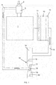
- Figure 1 is a schematic overview of the cooling air and pre-cleaner systems of an internal combustion engine in a work machine according to the invention.
- Figure 1 is a schematic view of the cooling air supply system and engine pre-cleaner system of an internal combustion engine in a work machine according to the invention.
- the arrows indicate the direction of flow through various components.
- the expressions 'upstream' and 'downstream' are to be understood with regard to the thus indicated flow directions.
- the work machine is a combine harvester, but the invention is applicable to any work machine that is operable in similar dusty or contaminated environments, such as any kind of forestry or construction vehicle.
- the engine 1 is visible, supplied with air through air inlet 2.
- An air pre-cleaner 3 is mounted in the inlet duct, usually upstream of an air filter (not shown).
- the pre-cleaner may operate according to any known process, for example using centrifugal forces to separate heavier particles in the combustion air from lighter particles. The heavier particles are then removed from the pre-cleaner via a duct 5, while the main air flow including lighter particles continues towards the engine (with lighter particles being removed by the air filter).
- the engine is cooled by a liquid coolant that is constantly circulated through a radiator 10, where the coolant is cooled by an air flow produced by a cooling air fan 11, driven by the engine 1.
- a screen 12 is mounted before the radiator. This may be a rotating screen as known in the art.
- the debris collected by the screen 12 is evacuated through a duct 13, by the suction created by an aspirator 14 comprising a rotatable fan mounted in a housing.
- the aspirator fan may be driven by the engine through a suitable pulley system or by an independent power source. All the components described so far are known as such in the art.
- a venturi element 16 is mounted downstream of the aspirator 14.
- the venturi element is directly coupled to the output port 15 of the aspirator 14.
- the cross section of the venturi element decreases progressively in a first portion 17, referred to as the inlet portion, until it reaches a minimum in a second portion, referred to as the throat portion 18, after which the cross-section progressively increases again in a third portion 19, referred to as the outlet portion.
- the duct 5 that is connected at one end to the combustion air pre-cleaner 3 is connected at the other end to the throat portion 18 of the venturi element.
- the acceleration of the flow through the throat portion 18 causes a suction effect which attracts an air flow containing the particles extracted by the pre-cleaner 3. These particles are evacuated together with the debris collected by the screen 12, through the outlet portion 19 and the outlet section 20 of the venturi element.
- a number of design parameters and operational parameters such as the dimensions of the various ducts 5, 13, the type and dimensions of the aspirator 14, the speed of the aspirator fan, the dimensions of the venturi element 16 etc, are configured to produce a flow in the throat portion 18 that generates a sufficient suction effect to attract the particles exiting the pre-cleaner 3.
- the mixing of debris coming from the screen 12 and particles coming from the pre-cleaner 3 takes place downstream of the aspirator 14, so that the operation of the aspirator is not negatively affected in the manner described in the introduction of the known prior art.
- the particles coming from the pre-cleaner 3 are not coming in contact with the rotating aspirator fan 14 which results in better performance, and less wear of the rotating parts as well as the housing of the aspirator 14.
- the venturi in the outlet of the aspirator 14, the duct 13 from the dust screen 12 towards the aspirator 14 is not affected directly.
Landscapes
- Engineering & Computer Science (AREA)
- Chemical & Material Sciences (AREA)
- Combustion & Propulsion (AREA)
- Mechanical Engineering (AREA)
- General Engineering & Computer Science (AREA)
- Combines (AREA)
Abstract
Description
- The present invention is related to work machines, such as agricultural harvesting machines for gathering and processing crop material from a field. The invention is in particular related to an improved means for the removal of dust and particles from an air pre-cleaner provided for the internal combustion engine that is powering the work machine.
- Work machines are generally operating in environments that impose important requirements on the cleaning of the air used in the internal combustion process of the driving engine. This is especially true for agricultural machines. An air pre-cleaner is therefore provided in these machines, designed to remove larger particles of dust, straw or other contaminants from the air prior to the air's introduction in the air filter of the engine. The removal of these unwanted elements from the pre-cleaner takes place through aspiration, by way of a suction source located elsewhere in the machine. A number of possible solutions have been documented.
- One possibility is to install an aspirator in the engine exhaust, as illustrated for example by
EP-A-313763 US-A-7878171 , wherein a venturi device is placed upstream of a fan that works as an aspirator for removing debris from the cooling air, the debris being collected by a rotating screen placed in front of the engine radiator. A pipe connects the outlet of the engine air pre-cleaner to the throat section of the venturi device, thereby aspirating dust and other particles from the pre-cleaner. These particles thereby join the flow of debris removed from the cooling air at a location upstream of the aspirator fan. While this solution removes the fire hazard and instability problems, the joining of the particle stream from the pre-cleaner and the debris stream from the radiator reduces the efficiency of the aspirator fan and may cause damage to the fan and fan housing because of hard particles coming from the pre-cleaner. This problem is solved in the agricultural machine shown inUS2010/0006361 , which comprises an aspirator fan comprising one housing and multiple fan chambers, so that aspiration of the cooling air debris and of the pre-cleaner output remains separated. This is a solution but it is technically complex and expensive. - The present invention is related to a work machine as disclosed in the appended claims. According to the invention, a venturi element is mounted downstream of the aspirator fan, said venturi element being connected to the outlet of the engine air pre-cleaner. This design ensures a better performance of the aspirator.
-
Figure 1 is a schematic overview of the cooling air and pre-cleaner systems of an internal combustion engine in a work machine according to the invention. - Preferred embodiments will now be described with reference to the drawings. The detailed description is not limiting the scope of the invention, which is defined only by the appended claims.
Figure 1 is a schematic view of the cooling air supply system and engine pre-cleaner system of an internal combustion engine in a work machine according to the invention. The arrows indicate the direction of flow through various components. The expressions 'upstream' and 'downstream' are to be understood with regard to the thus indicated flow directions. According to a preferred embodiment, the work machine is a combine harvester, but the invention is applicable to any work machine that is operable in similar dusty or contaminated environments, such as any kind of forestry or construction vehicle. Theengine 1 is visible, supplied with air throughair inlet 2. An air pre-cleaner 3 is mounted in the inlet duct, usually upstream of an air filter (not shown). The pre-cleaner may operate according to any known process, for example using centrifugal forces to separate heavier particles in the combustion air from lighter particles. The heavier particles are then removed from the pre-cleaner via aduct 5, while the main air flow including lighter particles continues towards the engine (with lighter particles being removed by the air filter). - The engine is cooled by a liquid coolant that is constantly circulated through a
radiator 10, where the coolant is cooled by an air flow produced by acooling air fan 11, driven by theengine 1. To prevent clogging of the radiator by debris from the air flow, ascreen 12 is mounted before the radiator. This may be a rotating screen as known in the art. The debris collected by thescreen 12 is evacuated through aduct 13, by the suction created by anaspirator 14 comprising a rotatable fan mounted in a housing. The aspirator fan may be driven by the engine through a suitable pulley system or by an independent power source. All the components described so far are known as such in the art. - According to the invention, a
venturi element 16 is mounted downstream of theaspirator 14. Preferably the venturi element is directly coupled to theoutput port 15 of theaspirator 14. When passing through the venturi element in the direction of flow exiting theaspirator 14, the cross section of the venturi element decreases progressively in afirst portion 17, referred to as the inlet portion, until it reaches a minimum in a second portion, referred to as thethroat portion 18, after which the cross-section progressively increases again in athird portion 19, referred to as the outlet portion. Theduct 5 that is connected at one end to the combustion air pre-cleaner 3 is connected at the other end to thethroat portion 18 of the venturi element. The acceleration of the flow through thethroat portion 18 causes a suction effect which attracts an air flow containing the particles extracted by the pre-cleaner 3. These particles are evacuated together with the debris collected by thescreen 12, through theoutlet portion 19 and theoutlet section 20 of the venturi element. A number of design parameters and operational parameters, such as the dimensions of thevarious ducts aspirator 14, the speed of the aspirator fan, the dimensions of theventuri element 16 etc, are configured to produce a flow in thethroat portion 18 that generates a sufficient suction effect to attract the particles exiting the pre-cleaner 3. - By placing a venturi element downstream of the
aspirator 14, the mixing of debris coming from thescreen 12 and particles coming from the pre-cleaner 3 takes place downstream of theaspirator 14, so that the operation of the aspirator is not negatively affected in the manner described in the introduction of the known prior art. The particles coming from the pre-cleaner 3 are not coming in contact with the rotatingaspirator fan 14 which results in better performance, and less wear of the rotating parts as well as the housing of theaspirator 14. Furthermore, by placing the venturi in the outlet of theaspirator 14, theduct 13 from thedust screen 12 towards theaspirator 14 is not affected directly. In the design ofUS7878171 , the section of this duct must be adapted - compared to a machine without a venturi - to the increased air flow that is flowing towards the aspirator. The present invention does not require adapting theduct 13, so that existing work machines can be more easily modified to work according to the invention.
Claims (3)
- A work machine comprising• an internal combustion engine (1) provided with an air inlet (2) for receiving combustion air, wherein an air pre-cleaner (3) is mounted in the inlet,• a radiator (10), a cooling air fan (11) and a debris removal means , configured to remove debris from a flow of air produced by the cooling air fan through the radiator, the removal means comprising a screen (12) for collecting the debris, and an aspirator (14) for aspirating the debris away from the screen,• a venturi element (16) mounted downstream of the aspirator (14), and having an inlet portion (17), a throat portion (18) and an outlet portion (19), wherein a duct (5) is mounted between the engine air pre-cleaner (3) and the throat portion (18), so that particles removed from the combustion air by the pre-cleaner (3) flow towards the throat portion (18), and out through the outlet portion of the venturi element, together with the debris aspirated from the debris removal means.
- Work machine according to claim 1, wherein the aspirator (14) comprises an output port (15) and wherein the venturi element (16) is coupled directly to said output port (15) of the aspirator (14).
- Work machine according to claim 1, wherein said work machine is a combine harvester.
Applications Claiming Priority (1)
| Application Number | Priority Date | Filing Date | Title |
|---|---|---|---|
| BE2014/0859A BE1022549B1 (en) | 2014-12-19 | 2014-12-19 | SYSTEM FOR DRAINING DUST AND PARTICLES FROM THE AIR FILTER OF THE COMBUSTION ENGINE OF A WORK MACHINE |
Publications (2)
| Publication Number | Publication Date |
|---|---|
| EP3034830A1 true EP3034830A1 (en) | 2016-06-22 |
| EP3034830B1 EP3034830B1 (en) | 2017-07-19 |
Family
ID=53373217
Family Applications (1)
| Application Number | Title | Priority Date | Filing Date |
|---|---|---|---|
| EP15200485.9A Active EP3034830B1 (en) | 2014-12-19 | 2015-12-16 | Engine air pre cleaner evacuation system for work machine |
Country Status (3)
| Country | Link |
|---|---|
| US (1) | US10024277B2 (en) |
| EP (1) | EP3034830B1 (en) |
| BE (1) | BE1022549B1 (en) |
Cited By (1)
| Publication number | Priority date | Publication date | Assignee | Title |
|---|---|---|---|---|
| WO2019126335A1 (en) * | 2017-12-19 | 2019-06-27 | Cnh Industrial America Llc | Cooling systems and methods for an agricultural harvester |
Families Citing this family (3)
| Publication number | Priority date | Publication date | Assignee | Title |
|---|---|---|---|---|
| CN108825528B (en) * | 2018-06-26 | 2020-03-27 | 安徽悦达环保科技有限公司 | An insect-proof fan without dust removal |
| DE102020200950A1 (en) * | 2020-01-27 | 2021-07-29 | Deere & Company | Extraction arrangement for a centrifugal air filter |
| US11938437B2 (en) * | 2021-02-04 | 2024-03-26 | Transportation Ip Holdings, Llc | Filter system and method |
Citations (6)
| Publication number | Priority date | Publication date | Assignee | Title |
|---|---|---|---|---|
| EP0313763A1 (en) | 1987-10-28 | 1989-05-03 | Deere & Company | Agricultural vehicle having a rotary screen air filter |
| US5466189A (en) * | 1994-08-18 | 1995-11-14 | Deere & Company | Cleaner for a rotating screen on a harvester |
| EP1262645A2 (en) * | 2001-05-30 | 2002-12-04 | Maschinenfabrik Bernard Krone GmbH | Self-propelled harvester |
| EP2136066A2 (en) * | 2008-06-17 | 2009-12-23 | Deere & Company | Engine cooling flow debris cleaner and air pre-cleaner aspirator |
| US20100006361A1 (en) | 2008-07-14 | 2010-01-14 | Vandike Nathan R | Agricultural machine having dedicated multi-section fan unit |
| DE102012018571B3 (en) * | 2012-09-20 | 2013-10-24 | Voith Patent Gmbh | Cooling system for diesel engine of e.g. tractor, has suction line that is connected to throat of venturi nozzle for sucking particles filtered from air filter |
Family Cites Families (3)
| Publication number | Priority date | Publication date | Assignee | Title |
|---|---|---|---|---|
| US5190217A (en) * | 1991-08-26 | 1993-03-02 | Air Pressure Damp-Proofing Service, Inc. | Applicator gun for applying surface coatings |
| US7682413B2 (en) | 2006-10-16 | 2010-03-23 | Deere & Company | Air precleaner arrangement for an internal combustion engine comprising two cyclone filters |
| DE102009047343A1 (en) * | 2009-12-01 | 2011-06-09 | Deere & Company, Moline | Drive arrangement and method for a work machine with two internal combustion engines |
-
2014
- 2014-12-19 BE BE2014/0859A patent/BE1022549B1/en not_active IP Right Cessation
-
2015
- 2015-12-16 EP EP15200485.9A patent/EP3034830B1/en active Active
- 2015-12-18 US US14/974,923 patent/US10024277B2/en active Active
Patent Citations (7)
| Publication number | Priority date | Publication date | Assignee | Title |
|---|---|---|---|---|
| EP0313763A1 (en) | 1987-10-28 | 1989-05-03 | Deere & Company | Agricultural vehicle having a rotary screen air filter |
| US5466189A (en) * | 1994-08-18 | 1995-11-14 | Deere & Company | Cleaner for a rotating screen on a harvester |
| EP1262645A2 (en) * | 2001-05-30 | 2002-12-04 | Maschinenfabrik Bernard Krone GmbH | Self-propelled harvester |
| EP2136066A2 (en) * | 2008-06-17 | 2009-12-23 | Deere & Company | Engine cooling flow debris cleaner and air pre-cleaner aspirator |
| US7878171B2 (en) | 2008-06-17 | 2011-02-01 | Deere & Company | Engine cooling flow debris cleaner and air pre-cleaner aspirator |
| US20100006361A1 (en) | 2008-07-14 | 2010-01-14 | Vandike Nathan R | Agricultural machine having dedicated multi-section fan unit |
| DE102012018571B3 (en) * | 2012-09-20 | 2013-10-24 | Voith Patent Gmbh | Cooling system for diesel engine of e.g. tractor, has suction line that is connected to throat of venturi nozzle for sucking particles filtered from air filter |
Cited By (2)
| Publication number | Priority date | Publication date | Assignee | Title |
|---|---|---|---|---|
| WO2019126335A1 (en) * | 2017-12-19 | 2019-06-27 | Cnh Industrial America Llc | Cooling systems and methods for an agricultural harvester |
| US10479191B2 (en) | 2017-12-19 | 2019-11-19 | Cnh Industrial America Llc | Cooling systems and methods for an agricultural harvester |
Also Published As
| Publication number | Publication date |
|---|---|
| EP3034830B1 (en) | 2017-07-19 |
| US20160177894A1 (en) | 2016-06-23 |
| BE1022549B1 (en) | 2016-05-27 |
| US10024277B2 (en) | 2018-07-17 |
Similar Documents
| Publication | Publication Date | Title |
|---|---|---|
| US7878171B2 (en) | Engine cooling flow debris cleaner and air pre-cleaner aspirator | |
| EP2949912B1 (en) | System and method for controlling an electric aspirator of an air intake system for a work vehicle | |
| US10118115B2 (en) | Centripetal separation system for cleaning particulate-pervaded air or gas | |
| EP2920451B1 (en) | Air intake system for a work vehicle | |
| EP1918009B1 (en) | Air precleaner arrangement for an internal combustionengine comprising two cyclone filters | |
| US7833301B2 (en) | Engine exhaust cooler and air pre-cleaner aspirator | |
| EP3034830B1 (en) | Engine air pre cleaner evacuation system for work machine | |
| US20180242804A1 (en) | Dust-removal apparatuses and associated methods | |
| EP1950407A2 (en) | Pre-cleaner aspiration system | |
| BR0213332B1 (en) | energized air cleaning system and process. | |
| CN208281092U (en) | Air inlet distribution system | |
| EP1733605A2 (en) | Rotating filter screen assembly | |
| EP3014097B1 (en) | Air intake arrangement for engine | |
| US11374467B2 (en) | Air pre-cleaning assembly and electric tool having same | |
| US6004382A (en) | Air cleaning system for vehicle cooling system and engine and cab | |
| JP7129951B2 (en) | work machine | |
| JP6751531B2 (en) | Combine drive structure | |
| SE538986C2 (en) | Arrangements in connection with air filters | |
| WO2025078893A1 (en) | Cyclonic air filter | |
| WO2025037079A1 (en) | Extraction hood | |
| KR20120006812U (en) | Dustproof screen of combine harvester | |
| KR20120006813U (en) | Straw removal structure for screen net of combine | |
| BR102019003422A2 (en) | suction system for a work vehicle | |
| JPH03199617A (en) | Air dust collector | |
| ITMI20131395A1 (en) | "SUCTION SYSTEM FOR AGRICULTURAL HARVESTING MACHINE" |
Legal Events
| Date | Code | Title | Description |
|---|---|---|---|
| PUAI | Public reference made under article 153(3) epc to a published international application that has entered the european phase |
Free format text: ORIGINAL CODE: 0009012 |
|
| AK | Designated contracting states |
Kind code of ref document: A1 Designated state(s): AL AT BE BG CH CY CZ DE DK EE ES FI FR GB GR HR HU IE IS IT LI LT LU LV MC MK MT NL NO PL PT RO RS SE SI SK SM TR |
|
| AX | Request for extension of the european patent |
Extension state: BA ME |
|
| STAA | Information on the status of an ep patent application or granted ep patent |
Free format text: STATUS: REQUEST FOR EXAMINATION WAS MADE |
|
| 17P | Request for examination filed |
Effective date: 20161222 |
|
| RBV | Designated contracting states (corrected) |
Designated state(s): AL AT BE BG CH CY CZ DE DK EE ES FI FR GB GR HR HU IE IS IT LI LT LU LV MC MK MT NL NO PL PT RO RS SE SI SK SM TR |
|
| GRAP | Despatch of communication of intention to grant a patent |
Free format text: ORIGINAL CODE: EPIDOSNIGR1 |
|
| STAA | Information on the status of an ep patent application or granted ep patent |
Free format text: STATUS: GRANT OF PATENT IS INTENDED |
|
| RIC1 | Information provided on ipc code assigned before grant |
Ipc: F01P 11/12 20060101AFI20170130BHEP Ipc: F02M 35/08 20060101ALI20170130BHEP |
|
| INTG | Intention to grant announced |
Effective date: 20170221 |
|
| GRAS | Grant fee paid |
Free format text: ORIGINAL CODE: EPIDOSNIGR3 |
|
| GRAA | (expected) grant |
Free format text: ORIGINAL CODE: 0009210 |
|
| STAA | Information on the status of an ep patent application or granted ep patent |
Free format text: STATUS: THE PATENT HAS BEEN GRANTED |
|
| AK | Designated contracting states |
Kind code of ref document: B1 Designated state(s): AL AT BE BG CH CY CZ DE DK EE ES FI FR GB GR HR HU IE IS IT LI LT LU LV MC MK MT NL NO PL PT RO RS SE SI SK SM TR |
|
| REG | Reference to a national code |
Ref country code: GB Ref legal event code: FG4D |
|
| REG | Reference to a national code |
Ref country code: CH Ref legal event code: EP |
|
| REG | Reference to a national code |
Ref country code: IE Ref legal event code: FG4D |
|
| REG | Reference to a national code |
Ref country code: AT Ref legal event code: REF Ref document number: 910626 Country of ref document: AT Kind code of ref document: T Effective date: 20170815 |
|
| REG | Reference to a national code |
Ref country code: DE Ref legal event code: R096 Ref document number: 602015003665 Country of ref document: DE |
|
| REG | Reference to a national code |
Ref country code: FR Ref legal event code: PLFP Year of fee payment: 3 |
|
| REG | Reference to a national code |
Ref country code: NL Ref legal event code: MP Effective date: 20170719 |
|
| REG | Reference to a national code |
Ref country code: LT Ref legal event code: MG4D |
|
| REG | Reference to a national code |
Ref country code: AT Ref legal event code: MK05 Ref document number: 910626 Country of ref document: AT Kind code of ref document: T Effective date: 20170719 |
|
| PG25 | Lapsed in a contracting state [announced via postgrant information from national office to epo] |
Ref country code: FI Free format text: LAPSE BECAUSE OF FAILURE TO SUBMIT A TRANSLATION OF THE DESCRIPTION OR TO PAY THE FEE WITHIN THE PRESCRIBED TIME-LIMIT Effective date: 20170719 Ref country code: AT Free format text: LAPSE BECAUSE OF FAILURE TO SUBMIT A TRANSLATION OF THE DESCRIPTION OR TO PAY THE FEE WITHIN THE PRESCRIBED TIME-LIMIT Effective date: 20170719 Ref country code: LT Free format text: LAPSE BECAUSE OF FAILURE TO SUBMIT A TRANSLATION OF THE DESCRIPTION OR TO PAY THE FEE WITHIN THE PRESCRIBED TIME-LIMIT Effective date: 20170719 Ref country code: SE Free format text: LAPSE BECAUSE OF FAILURE TO SUBMIT A TRANSLATION OF THE DESCRIPTION OR TO PAY THE FEE WITHIN THE PRESCRIBED TIME-LIMIT Effective date: 20170719 Ref country code: NL Free format text: LAPSE BECAUSE OF FAILURE TO SUBMIT A TRANSLATION OF THE DESCRIPTION OR TO PAY THE FEE WITHIN THE PRESCRIBED TIME-LIMIT Effective date: 20170719 Ref country code: HR Free format text: LAPSE BECAUSE OF FAILURE TO SUBMIT A TRANSLATION OF THE DESCRIPTION OR TO PAY THE FEE WITHIN THE PRESCRIBED TIME-LIMIT Effective date: 20170719 Ref country code: NO Free format text: LAPSE BECAUSE OF FAILURE TO SUBMIT A TRANSLATION OF THE DESCRIPTION OR TO PAY THE FEE WITHIN THE PRESCRIBED TIME-LIMIT Effective date: 20171019 |
|
| PG25 | Lapsed in a contracting state [announced via postgrant information from national office to epo] |
Ref country code: IS Free format text: LAPSE BECAUSE OF FAILURE TO SUBMIT A TRANSLATION OF THE DESCRIPTION OR TO PAY THE FEE WITHIN THE PRESCRIBED TIME-LIMIT Effective date: 20171119 Ref country code: BG Free format text: LAPSE BECAUSE OF FAILURE TO SUBMIT A TRANSLATION OF THE DESCRIPTION OR TO PAY THE FEE WITHIN THE PRESCRIBED TIME-LIMIT Effective date: 20171019 Ref country code: PL Free format text: LAPSE BECAUSE OF FAILURE TO SUBMIT A TRANSLATION OF THE DESCRIPTION OR TO PAY THE FEE WITHIN THE PRESCRIBED TIME-LIMIT Effective date: 20170719 Ref country code: LV Free format text: LAPSE BECAUSE OF FAILURE TO SUBMIT A TRANSLATION OF THE DESCRIPTION OR TO PAY THE FEE WITHIN THE PRESCRIBED TIME-LIMIT Effective date: 20170719 Ref country code: ES Free format text: LAPSE BECAUSE OF FAILURE TO SUBMIT A TRANSLATION OF THE DESCRIPTION OR TO PAY THE FEE WITHIN THE PRESCRIBED TIME-LIMIT Effective date: 20170719 Ref country code: GR Free format text: LAPSE BECAUSE OF FAILURE TO SUBMIT A TRANSLATION OF THE DESCRIPTION OR TO PAY THE FEE WITHIN THE PRESCRIBED TIME-LIMIT Effective date: 20171020 Ref country code: RS Free format text: LAPSE BECAUSE OF FAILURE TO SUBMIT A TRANSLATION OF THE DESCRIPTION OR TO PAY THE FEE WITHIN THE PRESCRIBED TIME-LIMIT Effective date: 20170719 |
|
| REG | Reference to a national code |
Ref country code: DE Ref legal event code: R097 Ref document number: 602015003665 Country of ref document: DE |
|
| PG25 | Lapsed in a contracting state [announced via postgrant information from national office to epo] |
Ref country code: RO Free format text: LAPSE BECAUSE OF FAILURE TO SUBMIT A TRANSLATION OF THE DESCRIPTION OR TO PAY THE FEE WITHIN THE PRESCRIBED TIME-LIMIT Effective date: 20170719 Ref country code: DK Free format text: LAPSE BECAUSE OF FAILURE TO SUBMIT A TRANSLATION OF THE DESCRIPTION OR TO PAY THE FEE WITHIN THE PRESCRIBED TIME-LIMIT Effective date: 20170719 Ref country code: CZ Free format text: LAPSE BECAUSE OF FAILURE TO SUBMIT A TRANSLATION OF THE DESCRIPTION OR TO PAY THE FEE WITHIN THE PRESCRIBED TIME-LIMIT Effective date: 20170719 |
|
| PLBE | No opposition filed within time limit |
Free format text: ORIGINAL CODE: 0009261 |
|
| STAA | Information on the status of an ep patent application or granted ep patent |
Free format text: STATUS: NO OPPOSITION FILED WITHIN TIME LIMIT |
|
| PG25 | Lapsed in a contracting state [announced via postgrant information from national office to epo] |
Ref country code: SM Free format text: LAPSE BECAUSE OF FAILURE TO SUBMIT A TRANSLATION OF THE DESCRIPTION OR TO PAY THE FEE WITHIN THE PRESCRIBED TIME-LIMIT Effective date: 20170719 Ref country code: SK Free format text: LAPSE BECAUSE OF FAILURE TO SUBMIT A TRANSLATION OF THE DESCRIPTION OR TO PAY THE FEE WITHIN THE PRESCRIBED TIME-LIMIT Effective date: 20170719 Ref country code: EE Free format text: LAPSE BECAUSE OF FAILURE TO SUBMIT A TRANSLATION OF THE DESCRIPTION OR TO PAY THE FEE WITHIN THE PRESCRIBED TIME-LIMIT Effective date: 20170719 |
|
| 26N | No opposition filed |
Effective date: 20180420 |
|
| PG25 | Lapsed in a contracting state [announced via postgrant information from national office to epo] |
Ref country code: SI Free format text: LAPSE BECAUSE OF FAILURE TO SUBMIT A TRANSLATION OF THE DESCRIPTION OR TO PAY THE FEE WITHIN THE PRESCRIBED TIME-LIMIT Effective date: 20170719 |
|
| REG | Reference to a national code |
Ref country code: IE Ref legal event code: MM4A |
|
| PG25 | Lapsed in a contracting state [announced via postgrant information from national office to epo] |
Ref country code: MT Free format text: LAPSE BECAUSE OF NON-PAYMENT OF DUE FEES Effective date: 20171216 Ref country code: LU Free format text: LAPSE BECAUSE OF NON-PAYMENT OF DUE FEES Effective date: 20171216 |
|
| REG | Reference to a national code |
Ref country code: FR Ref legal event code: PLFP Year of fee payment: 4 Ref country code: BE Ref legal event code: MM Effective date: 20171231 |
|
| PG25 | Lapsed in a contracting state [announced via postgrant information from national office to epo] |
Ref country code: IE Free format text: LAPSE BECAUSE OF NON-PAYMENT OF DUE FEES Effective date: 20171216 |
|
| PG25 | Lapsed in a contracting state [announced via postgrant information from national office to epo] |
Ref country code: BE Free format text: LAPSE BECAUSE OF NON-PAYMENT OF DUE FEES Effective date: 20171231 |
|
| PG25 | Lapsed in a contracting state [announced via postgrant information from national office to epo] |
Ref country code: MC Free format text: LAPSE BECAUSE OF FAILURE TO SUBMIT A TRANSLATION OF THE DESCRIPTION OR TO PAY THE FEE WITHIN THE PRESCRIBED TIME-LIMIT Effective date: 20170719 Ref country code: HU Free format text: LAPSE BECAUSE OF FAILURE TO SUBMIT A TRANSLATION OF THE DESCRIPTION OR TO PAY THE FEE WITHIN THE PRESCRIBED TIME-LIMIT; INVALID AB INITIO Effective date: 20151216 |
|
| REG | Reference to a national code |
Ref country code: CH Ref legal event code: PL |
|
| PG25 | Lapsed in a contracting state [announced via postgrant information from national office to epo] |
Ref country code: CY Free format text: LAPSE BECAUSE OF FAILURE TO SUBMIT A TRANSLATION OF THE DESCRIPTION OR TO PAY THE FEE WITHIN THE PRESCRIBED TIME-LIMIT Effective date: 20170719 |
|
| PG25 | Lapsed in a contracting state [announced via postgrant information from national office to epo] |
Ref country code: MK Free format text: LAPSE BECAUSE OF FAILURE TO SUBMIT A TRANSLATION OF THE DESCRIPTION OR TO PAY THE FEE WITHIN THE PRESCRIBED TIME-LIMIT Effective date: 20170719 |
|
| PG25 | Lapsed in a contracting state [announced via postgrant information from national office to epo] |
Ref country code: LI Free format text: LAPSE BECAUSE OF NON-PAYMENT OF DUE FEES Effective date: 20181231 Ref country code: CH Free format text: LAPSE BECAUSE OF NON-PAYMENT OF DUE FEES Effective date: 20181231 |
|
| PG25 | Lapsed in a contracting state [announced via postgrant information from national office to epo] |
Ref country code: TR Free format text: LAPSE BECAUSE OF FAILURE TO SUBMIT A TRANSLATION OF THE DESCRIPTION OR TO PAY THE FEE WITHIN THE PRESCRIBED TIME-LIMIT Effective date: 20170719 |
|
| PG25 | Lapsed in a contracting state [announced via postgrant information from national office to epo] |
Ref country code: PT Free format text: LAPSE BECAUSE OF FAILURE TO SUBMIT A TRANSLATION OF THE DESCRIPTION OR TO PAY THE FEE WITHIN THE PRESCRIBED TIME-LIMIT Effective date: 20170719 |
|
| REG | Reference to a national code |
Ref country code: DE Ref legal event code: R082 Ref document number: 602015003665 Country of ref document: DE Representative=s name: MEISSNER BOLTE PATENTANWAELTE RECHTSANWAELTE P, DE |
|
| PG25 | Lapsed in a contracting state [announced via postgrant information from national office to epo] |
Ref country code: AL Free format text: LAPSE BECAUSE OF FAILURE TO SUBMIT A TRANSLATION OF THE DESCRIPTION OR TO PAY THE FEE WITHIN THE PRESCRIBED TIME-LIMIT Effective date: 20170719 |
|
| PGFP | Annual fee paid to national office [announced via postgrant information from national office to epo] |
Ref country code: GB Payment date: 20231218 Year of fee payment: 9 |
|
| GBPC | Gb: european patent ceased through non-payment of renewal fee |
Effective date: 20241216 |
|
| PG25 | Lapsed in a contracting state [announced via postgrant information from national office to epo] |
Ref country code: GB Free format text: LAPSE BECAUSE OF NON-PAYMENT OF DUE FEES Effective date: 20241216 |
|
| PGFP | Annual fee paid to national office [announced via postgrant information from national office to epo] |
Ref country code: IT Payment date: 20251218 Year of fee payment: 11 |
|
| PGFP | Annual fee paid to national office [announced via postgrant information from national office to epo] |
Ref country code: FR Payment date: 20251223 Year of fee payment: 11 |
|
| PGFP | Annual fee paid to national office [announced via postgrant information from national office to epo] |
Ref country code: DE Payment date: 20251229 Year of fee payment: 11 |