EP3034827A1 - Procédé de diagnostic d'un piège à oxydes d'azote et dispositif associé - Google Patents
Procédé de diagnostic d'un piège à oxydes d'azote et dispositif associé Download PDFInfo
- Publication number
- EP3034827A1 EP3034827A1 EP15199474.6A EP15199474A EP3034827A1 EP 3034827 A1 EP3034827 A1 EP 3034827A1 EP 15199474 A EP15199474 A EP 15199474A EP 3034827 A1 EP3034827 A1 EP 3034827A1
- Authority
- EP
- European Patent Office
- Prior art keywords
- trap
- richness
- threshold
- criterion
- purge
- Prior art date
- Legal status (The legal status is an assumption and is not a legal conclusion. Google has not performed a legal analysis and makes no representation as to the accuracy of the status listed.)
- Granted
Links
Images

Classifications
-
- F—MECHANICAL ENGINEERING; LIGHTING; HEATING; WEAPONS; BLASTING
- F01—MACHINES OR ENGINES IN GENERAL; ENGINE PLANTS IN GENERAL; STEAM ENGINES
- F01N—GAS-FLOW SILENCERS OR EXHAUST APPARATUS FOR MACHINES OR ENGINES IN GENERAL; GAS-FLOW SILENCERS OR EXHAUST APPARATUS FOR INTERNAL-COMBUSTION ENGINES
- F01N11/00—Monitoring or diagnostic devices for exhaust-gas treatment apparatus
- F01N11/007—Monitoring or diagnostic devices for exhaust-gas treatment apparatus the diagnostic devices measuring oxygen or air concentration downstream of the exhaust apparatus
-
- F—MECHANICAL ENGINEERING; LIGHTING; HEATING; WEAPONS; BLASTING
- F01—MACHINES OR ENGINES IN GENERAL; ENGINE PLANTS IN GENERAL; STEAM ENGINES
- F01N—GAS-FLOW SILENCERS OR EXHAUST APPARATUS FOR MACHINES OR ENGINES IN GENERAL; GAS-FLOW SILENCERS OR EXHAUST APPARATUS FOR INTERNAL-COMBUSTION ENGINES
- F01N3/00—Exhaust or silencing apparatus having means for purifying, rendering innocuous, or otherwise treating exhaust
- F01N3/08—Exhaust or silencing apparatus having means for purifying, rendering innocuous, or otherwise treating exhaust for rendering innocuous
- F01N3/0807—Exhaust or silencing apparatus having means for purifying, rendering innocuous, or otherwise treating exhaust for rendering innocuous by using absorbents or adsorbents
- F01N3/0814—Exhaust or silencing apparatus having means for purifying, rendering innocuous, or otherwise treating exhaust for rendering innocuous by using absorbents or adsorbents combined with catalytic converters, e.g. NOx absorption/storage reduction catalysts
-
- F—MECHANICAL ENGINEERING; LIGHTING; HEATING; WEAPONS; BLASTING
- F01—MACHINES OR ENGINES IN GENERAL; ENGINE PLANTS IN GENERAL; STEAM ENGINES
- F01N—GAS-FLOW SILENCERS OR EXHAUST APPARATUS FOR MACHINES OR ENGINES IN GENERAL; GAS-FLOW SILENCERS OR EXHAUST APPARATUS FOR INTERNAL-COMBUSTION ENGINES
- F01N2430/00—Influencing exhaust purification, e.g. starting of catalytic reaction, filter regeneration, or the like, by controlling engine operating characteristics
- F01N2430/06—Influencing exhaust purification, e.g. starting of catalytic reaction, filter regeneration, or the like, by controlling engine operating characteristics by varying fuel-air ratio, e.g. by enriching fuel-air mixture
-
- F—MECHANICAL ENGINEERING; LIGHTING; HEATING; WEAPONS; BLASTING
- F01—MACHINES OR ENGINES IN GENERAL; ENGINE PLANTS IN GENERAL; STEAM ENGINES
- F01N—GAS-FLOW SILENCERS OR EXHAUST APPARATUS FOR MACHINES OR ENGINES IN GENERAL; GAS-FLOW SILENCERS OR EXHAUST APPARATUS FOR INTERNAL-COMBUSTION ENGINES
- F01N2430/00—Influencing exhaust purification, e.g. starting of catalytic reaction, filter regeneration, or the like, by controlling engine operating characteristics
- F01N2430/08—Influencing exhaust purification, e.g. starting of catalytic reaction, filter regeneration, or the like, by controlling engine operating characteristics by modifying ignition or injection timing
- F01N2430/085—Influencing exhaust purification, e.g. starting of catalytic reaction, filter regeneration, or the like, by controlling engine operating characteristics by modifying ignition or injection timing at least a part of the injection taking place during expansion or exhaust stroke
-
- F—MECHANICAL ENGINEERING; LIGHTING; HEATING; WEAPONS; BLASTING
- F01—MACHINES OR ENGINES IN GENERAL; ENGINE PLANTS IN GENERAL; STEAM ENGINES
- F01N—GAS-FLOW SILENCERS OR EXHAUST APPARATUS FOR MACHINES OR ENGINES IN GENERAL; GAS-FLOW SILENCERS OR EXHAUST APPARATUS FOR INTERNAL-COMBUSTION ENGINES
- F01N2430/00—Influencing exhaust purification, e.g. starting of catalytic reaction, filter regeneration, or the like, by controlling engine operating characteristics
- F01N2430/10—Influencing exhaust purification, e.g. starting of catalytic reaction, filter regeneration, or the like, by controlling engine operating characteristics by modifying inlet or exhaust valve timing
-
- F—MECHANICAL ENGINEERING; LIGHTING; HEATING; WEAPONS; BLASTING
- F01—MACHINES OR ENGINES IN GENERAL; ENGINE PLANTS IN GENERAL; STEAM ENGINES
- F01N—GAS-FLOW SILENCERS OR EXHAUST APPARATUS FOR MACHINES OR ENGINES IN GENERAL; GAS-FLOW SILENCERS OR EXHAUST APPARATUS FOR INTERNAL-COMBUSTION ENGINES
- F01N2550/00—Monitoring or diagnosing the deterioration of exhaust systems
- F01N2550/02—Catalytic activity of catalytic converters
-
- F—MECHANICAL ENGINEERING; LIGHTING; HEATING; WEAPONS; BLASTING
- F01—MACHINES OR ENGINES IN GENERAL; ENGINE PLANTS IN GENERAL; STEAM ENGINES
- F01N—GAS-FLOW SILENCERS OR EXHAUST APPARATUS FOR MACHINES OR ENGINES IN GENERAL; GAS-FLOW SILENCERS OR EXHAUST APPARATUS FOR INTERNAL-COMBUSTION ENGINES
- F01N2550/00—Monitoring or diagnosing the deterioration of exhaust systems
- F01N2550/03—Monitoring or diagnosing the deterioration of exhaust systems of sorbing activity of adsorbents or absorbents
-
- F—MECHANICAL ENGINEERING; LIGHTING; HEATING; WEAPONS; BLASTING
- F01—MACHINES OR ENGINES IN GENERAL; ENGINE PLANTS IN GENERAL; STEAM ENGINES
- F01N—GAS-FLOW SILENCERS OR EXHAUST APPARATUS FOR MACHINES OR ENGINES IN GENERAL; GAS-FLOW SILENCERS OR EXHAUST APPARATUS FOR INTERNAL-COMBUSTION ENGINES
- F01N2560/00—Exhaust systems with means for detecting or measuring exhaust gas components or characteristics
- F01N2560/02—Exhaust systems with means for detecting or measuring exhaust gas components or characteristics the means being an exhaust gas sensor
- F01N2560/025—Exhaust systems with means for detecting or measuring exhaust gas components or characteristics the means being an exhaust gas sensor for measuring or detecting O2, e.g. lambda sensors
-
- F—MECHANICAL ENGINEERING; LIGHTING; HEATING; WEAPONS; BLASTING
- F01—MACHINES OR ENGINES IN GENERAL; ENGINE PLANTS IN GENERAL; STEAM ENGINES
- F01N—GAS-FLOW SILENCERS OR EXHAUST APPARATUS FOR MACHINES OR ENGINES IN GENERAL; GAS-FLOW SILENCERS OR EXHAUST APPARATUS FOR INTERNAL-COMBUSTION ENGINES
- F01N2900/00—Details of electrical control or of the monitoring of the exhaust gas treating apparatus
- F01N2900/04—Methods of control or diagnosing
- F01N2900/0404—Methods of control or diagnosing using a data filter
-
- F—MECHANICAL ENGINEERING; LIGHTING; HEATING; WEAPONS; BLASTING
- F01—MACHINES OR ENGINES IN GENERAL; ENGINE PLANTS IN GENERAL; STEAM ENGINES
- F01N—GAS-FLOW SILENCERS OR EXHAUST APPARATUS FOR MACHINES OR ENGINES IN GENERAL; GAS-FLOW SILENCERS OR EXHAUST APPARATUS FOR INTERNAL-COMBUSTION ENGINES
- F01N2900/00—Details of electrical control or of the monitoring of the exhaust gas treating apparatus
- F01N2900/04—Methods of control or diagnosing
- F01N2900/0418—Methods of control or diagnosing using integration or an accumulated value within an elapsed period
-
- F—MECHANICAL ENGINEERING; LIGHTING; HEATING; WEAPONS; BLASTING
- F01—MACHINES OR ENGINES IN GENERAL; ENGINE PLANTS IN GENERAL; STEAM ENGINES
- F01N—GAS-FLOW SILENCERS OR EXHAUST APPARATUS FOR MACHINES OR ENGINES IN GENERAL; GAS-FLOW SILENCERS OR EXHAUST APPARATUS FOR INTERNAL-COMBUSTION ENGINES
- F01N2900/00—Details of electrical control or of the monitoring of the exhaust gas treating apparatus
- F01N2900/06—Parameters used for exhaust control or diagnosing
- F01N2900/14—Parameters used for exhaust control or diagnosing said parameters being related to the exhaust gas
- F01N2900/1402—Exhaust gas composition
-
- F—MECHANICAL ENGINEERING; LIGHTING; HEATING; WEAPONS; BLASTING
- F01—MACHINES OR ENGINES IN GENERAL; ENGINE PLANTS IN GENERAL; STEAM ENGINES
- F01N—GAS-FLOW SILENCERS OR EXHAUST APPARATUS FOR MACHINES OR ENGINES IN GENERAL; GAS-FLOW SILENCERS OR EXHAUST APPARATUS FOR INTERNAL-COMBUSTION ENGINES
- F01N2900/00—Details of electrical control or of the monitoring of the exhaust gas treating apparatus
- F01N2900/06—Parameters used for exhaust control or diagnosing
- F01N2900/16—Parameters used for exhaust control or diagnosing said parameters being related to the exhaust apparatus, e.g. particulate filter or catalyst
- F01N2900/1621—Catalyst conversion efficiency
-
- F—MECHANICAL ENGINEERING; LIGHTING; HEATING; WEAPONS; BLASTING
- F01—MACHINES OR ENGINES IN GENERAL; ENGINE PLANTS IN GENERAL; STEAM ENGINES
- F01N—GAS-FLOW SILENCERS OR EXHAUST APPARATUS FOR MACHINES OR ENGINES IN GENERAL; GAS-FLOW SILENCERS OR EXHAUST APPARATUS FOR INTERNAL-COMBUSTION ENGINES
- F01N3/00—Exhaust or silencing apparatus having means for purifying, rendering innocuous, or otherwise treating exhaust
- F01N3/08—Exhaust or silencing apparatus having means for purifying, rendering innocuous, or otherwise treating exhaust for rendering innocuous
- F01N3/0807—Exhaust or silencing apparatus having means for purifying, rendering innocuous, or otherwise treating exhaust for rendering innocuous by using absorbents or adsorbents
- F01N3/0828—Exhaust or silencing apparatus having means for purifying, rendering innocuous, or otherwise treating exhaust for rendering innocuous by using absorbents or adsorbents characterised by the absorbed or adsorbed substances
- F01N3/0842—Nitrogen oxides
-
- Y—GENERAL TAGGING OF NEW TECHNOLOGICAL DEVELOPMENTS; GENERAL TAGGING OF CROSS-SECTIONAL TECHNOLOGIES SPANNING OVER SEVERAL SECTIONS OF THE IPC; TECHNICAL SUBJECTS COVERED BY FORMER USPC CROSS-REFERENCE ART COLLECTIONS [XRACs] AND DIGESTS
- Y02—TECHNOLOGIES OR APPLICATIONS FOR MITIGATION OR ADAPTATION AGAINST CLIMATE CHANGE
- Y02T—CLIMATE CHANGE MITIGATION TECHNOLOGIES RELATED TO TRANSPORTATION
- Y02T10/00—Road transport of goods or passengers
- Y02T10/10—Internal combustion engine [ICE] based vehicles
- Y02T10/40—Engine management systems
Definitions
- the invention relates to a method for diagnosing the operating state of a nitrogen oxide trap. It also relates to a device capable of implementing such a method. It finds an advantageous application in the form of a diagnosis embedded in a motor vehicle equipped with a diesel engine associated with a nitrogen oxide trap.
- a nitrogen oxide trap is generally placed in the exhaust line of a vehicle and operates discontinuously, in two distinct modes.
- the trap During normal operation of the lean-burn engine, the trap retains a portion of the NO x molecules emitted by the engine on different catalytic storage compartments, the rest being released into the atmosphere after passing through the trap.
- the percentage of NO x molecules in the engine that is retained by the trap is called storage efficiency.
- the regeneration phase consists of purging the NO x trap accumulated during the storage operation phase.
- reducing agents HC unburned hydrocarbons and carbon monoxide CO
- the regeneration phase consists of purging the NO x trap accumulated during the storage operation phase.
- reducing agents HC unburned hydrocarbons and carbon monoxide CO
- the storage efficiency of a nitrogen oxide trap decreases, because of the decrease in the number of catalytic compartments available in the trap for storing the NO x molecules.
- the Applicant has proposed that the mass of reducers for comparison with a threshold is determined during a special purge stage of the trap made for the purpose of diagnosis to a second value of engine operating richness which is greater than one first operating richness value of a normal purge step of the trap.
- the Applicant has proposed that the mass of reducing agents for comparison with a threshold is determined during a prolonged purge step after depletion of nitrogen oxides stored in the trap, that is to say at the beyond the duration of a normal purge.
- the invention proposes to remedy the lack of precision and the risks of erroneous diagnoses of the known diagnostic processes of the nitrogen oxide traps, without modifying the normal course of the purges of said traps.
- an internal combustion engine 1 for example a diesel engine of a motor vehicle.
- the engine 1 is supplied with air by an intake manifold 2 and fuel, for example diesel, by a plurality of injectors 3 mounted on a common rail 4 of fuel supply.
- the engine 1 is equipped with a flue gas exhaust system, comprising an exhaust manifold 5, an exhaust duct 6, a pollutant treatment device 7 of the engine 1 and an exhaust pipe 8. which the exhaust gases are discharged into the atmosphere.
- a flue gas exhaust system comprising an exhaust manifold 5, an exhaust duct 6, a pollutant treatment device 7 of the engine 1 and an exhaust pipe 8. which the exhaust gases are discharged into the atmosphere.
- the engine may be supercharged type and / or associated with at least one exhaust gas recirculation circuit without departing from the scope of the invention.
- the pollutant treatment device 7 is in the form of a metal casing (or “canning") of substantially cylindrical shape terminated at both ends by two connecting cones respectively with the exhaust pipe 6 and the muffler 8.
- This metal casing contains a nitrogen oxide trap 9.
- it may also include another exhaust gas treatment device 10, for example a particulate filter 10 or an oxidation catalyst 10, which is disposed here downstream of the trap 9 (in the direction of circulation of the exhaust gas represented by the arrows shown in FIG. figure 4 ).
- the nitrogen oxide trap 9 stores a portion of the NO x emissions from the engine 1 when the engine is operating in a lean mixture. Periodically, when a phase of operation of the engine 1 in rich mixture (called: regeneration phase, or purge phase) is triggered, the trap 9 reduces the NO x into nitrogen molecules N 2 and carbon dioxide CO 2 under the action of reducing agents, that is to say carbon monoxide and unburned hydrocarbon molecules emitted by the engine 1.
- the nitrogen oxide trap 9 is associated with means for determining the richness of the exhaust gases of the engine 1 respectively the richness at the input Ram and the richness at the output Rav of the trap 9, for example respectively a probe upstream oxygen 11, disposed on the exhaust pipe 6 upstream of the trap 9, and a downstream oxygen sensor 12, disposed on the exhaust pipe 8 downstream of the trap 9.
- An electronic engine computer (not shown) is connected to the engine 1, and to a set of sensors and actuators comprising at least the upstream and downstream oxygen sensors 11 and the injectors 3.
- the computer comprises means for adjusting the engine 1 during normal operation, in which it adjusts the fuel injections in the engine 1 so as to produce the torque necessary to drive the vehicle, the trap 9 being in the operating mode. storage of nitrogen oxides.
- It also comprises means for detecting a need to purge the trap 9, for example means capable of verifying that the mass of nitrogen oxides contained in the trap 9 has reached a threshold.
- the richness is set to an average value which is generally between 1.04 and 1.06, typically close to 1.05, which represents a good compromise between the duration of the purge and the amount of fuel consumed.
- the computer comprises means for determining a filtered richness value at the entrance of the trap Ram, f and a filtered richness value at the output of the trap Rav, f, for example low-pass filters capable of filtering respectively the richness signals at the input Ram and at the output Tav of the trap respectively received upstream oxygen sensors 11 and downstream 12.
- the calculator comprises means for detecting the end of the purge of the trap 9. For example, it can verify that the value of the downstream richness Rav received from the downstream oxygen probe 12 matches the value of the upstream wealth Ram received from the Alternatively, it can verify that the value of the downstream wealth Rav reaches a value of wealth greater than 1 predetermined, for example 1.04 as on the Figures 2 and 3 .
- the calculator comprises on the one hand means for calculating the absolute value
- the calculator further comprises means for calculating the absolute value
- the computer comprises means for comparing the first diagnostic criterion Cam with a first diagnostic threshold Sam, and means for comparing the second diagnostic criterion with a second diagnostic threshold Sav.
- the calculator comprises means capable of establishing that the trap 9 is in good condition when the first criterion Cam is lower than the first threshold Sam.
- it can comprise means able to establish that the diagnosis of the trap 9 is impossible and to switch setting the motor in its operating mode normal until the next purge.
- the calculator comprises means capable of establishing that the trap 9 is in good condition when the first criterion Cam is greater than the first threshold Sam and that the second criterion Cav is lower than the second threshold Sav.
- the calculator comprises means capable of establishing that the trap 9 is faulty when the first criterion Cav is greater than the first threshold Sam and the second criterion is greater than the second threshold Sav.
- the computer as well as the engine 1 and all the components represented on the figure 1 and which have just been described, are part of a diagnostic device for carrying out the method according to the invention.
- the Figures 2 and 3 are graphs showing the evolution of the richness at the Ram inlet and at the Rav exit of a nitrogen oxide trap 9 during a purge, in a device conforming to the figure 1 , respectively for a good trap and for a failing trap.
- the richness at the entrance Ram of the trap is represented in full line and the richness at the exit Rav of the trap is represented in mixed dash.
- the richness of the air / fuel mixture in the engine 1, as measured by the upstream probe 11, has been adjusted to a value of between 1.04 and 1.07.
- the beginning of the purge corresponds to the moment when the wealth at the entrance Ram of the trap 9 reaches 1.04.
- the end of the purge corresponds to the moment when the wealth at the exit Rav of the trap reaches in turn 1.04.
- the trap 9 good has a good treatment efficiency. It consumes all the reducers (fuel) that are brought to the trap entrance 9. This is not sensitive to the richness oscillations Ram of the upstream sensor 11. As few reducers are evacuated at the exit of the trap 9, the signal Rav of the downstream probe 12 oscillates much less, that is to say that it has amplitudes of oscillations much less marked than those of the Ram signal of the upstream probe 11.
- the faulty trap 9 has a low kinetic efficiency. It can consume only a portion of the reductants brought to the trap inlet, the remaining quantity being rejected at the exit of the trap 9.
- the downstream probe 12 measures a richness signal Rav, corresponding to these rejects, which is much closer to the richness signal Ram of the upstream probe 11. More precisely, it has amplitudes of oscillations which are much more marked than in the case of a trap in good condition. In other words, the signal Rav of the downstream probe 12 is here less damped.
- the accuracy of the diagnosis is advantageously improved by quantifying the prior to the oscillations of the upstream probe 11.
- the oscillations of the richness signal at the Ram input of the trap depend on the engine operating point and may have amplitudes more or less big.
- the oscillations of the richness at the entrance Ram of the trap are also very weak, whatever the state of the trap 9. Consequently, one will be able to be limited to declare a trap with nitrogen oxides failing only when the oscillations of the richness signal Ram at the entrance of the trap are strong and the oscillations of the richness signal Rav at the exit of the trap are also strong.
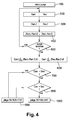
- the figure 4 is a flowchart of the steps of a method for diagnosing a nitrogen oxide trap 9 according to the invention.
- the engine computer monitors the accumulation of NO x in the nitrogen oxide trap 9.
- the diagnosis process begins, by a first step 100 of purge start of the trap 9.
- the method comprises a step 200 for determining the richness at the Ram input and the richness at the Rav output of the trap 9. It comprises a step 300 for determining a value of filtered richness at the input Ram, f of the trap and a wealth value filtered at the Rav exit, f of the trap.
- the method applies to the raw signals, that is to say as measured by the probes 11, 12, cross-pass type filtering which allows to eliminate micro-oscillations.
- the method comprises a step 400 of calculating, on the one hand, the absolute value of the difference between the richness at the entrance Ram of the trap and the filtered richness at the entrance Ram, f of the trap, and, on the other hand, share, of the absolute value of the difference between wealth at the Rav exit of the trap and the filtered wealth at the Rav exit, f of the trap.
- the method continues with a calculation step 600 of the first diagnostic criterion Cam and the second diagnostic criterion Cav, according to the equations 1 and 2 mentioned above.
- the method comprises a comparison step 700 of the first criterion Cam with the first threshold Sam. If the first criterion Cam is lower than the first threshold Sam, the method orients, without limitation, to a step 900 in which the trap 9 is judged. in good condition. Alternatively, the method can judge that the diagnosis is impossible, and rather direct to a motor adjustment step in its normal mode of operation in lean mixture, storage mode of nitrogen oxides. In other words, it will be necessary to wait for a new stage 100 of purge start to be able to carry out a new diagnosis. The judgment of the good or failed state of the trap is pushed back to at least the next purge of the trap (9).
- step 800 of the second diagnostic criterion Cav with the second threshold Sav. If the second criterion Cav is lower than the second threshold, the method orients to step 900. In the opposite case, it points to step 1000 in which the trap is judged to be faulty.
Landscapes
- Engineering & Computer Science (AREA)
- Chemical & Material Sciences (AREA)
- Chemical Kinetics & Catalysis (AREA)
- Combustion & Propulsion (AREA)
- Mechanical Engineering (AREA)
- General Engineering & Computer Science (AREA)
- Exhaust Gas After Treatment (AREA)
Abstract
Description
- L'invention concerne un procédé de diagnostic de l'état de fonctionnement d'un piège à oxydes d'azote. Elle concerne également un dispositif apte à la mise en oeuvre d'un tel procédé. Elle trouve une application avantageuse sous la forme d'un diagnostic embarqué dans un véhicule automobile équipé d'un moteur diesel associé à un piège à oxydes d'azotes.
- De nombreux moteurs modernes à combustion interne, en particulier les moteurs diesel des véhicules automobiles, sont équipés d'un piège à oxydes d'azote (NOx) pour respecter les normes légales qui limitent les émissions à l'échappement de polluants par ces véhicules.
- Un piège à oxydes d'azote est généralement placé dans la ligne d'échappement d'un véhicule et fonctionne de manière discontinue, selon deux modes distincts.
- Pendant le fonctionnement habituel du moteur en mélange pauvre, le piège retient une partie des molécules de NOx émises par le moteur sur différents compartiments catalytiques de stockage, le reste étant rejeté dans l'atmosphère après avoir traversé le piège. Le pourcentage de molécules de NOx du moteur qui est retenu par le piège est appelé efficacité de stockage.
- Quand la masse de NOx stockée dans le piège atteint un seuil prédéterminé en fonction de la capacité maximale de stockage, un basculement provoqué du fonctionnement du moteur en mélange riche, c'est-à-dire avec un défaut d'oxygène par rapport à la stoechiométrie, permet de régénérer le piège.
- La phase de régénération consiste à purger le piège des NOx accumulés lors de la phase de fonctionnement de stockage. Au cours de cette phase de fonctionnement en mélange riche, des réducteurs (hydrocarbures imbrûlés HC et monoxyde de carbone CO) provenant du moteur passent dans le piège et réduisent les molécules de NOx en molécules d'azote N2 et de dioxyde de carbone CO2.
- Sous l'effet du vieillissement, et parfois d'événements accidentels tels que des chocs thermiques ou mécaniques, l'efficacité de stockage d'un piège à oxydes d'azote diminue, à cause de la baisse du nombre de compartiments catalytiques disponibles dans le piège pour stocker les molécules de NOx.
- Pour s'assurer que les rejets dans l'atmosphère des gaz d'échappement d'un véhicule automobile sont en permanence conformes aux normes légales, il est courant de surveiller l'état de fonctionnement de son piège à oxydes d'azote, c'est-à-dire de tester son efficacité de stockage, grâce à un diagnostic embarqué.
- On connaît plusieurs procédés qui visent à surveiller l'état de fonctionnement d'un piège à oxydes d'azote. Plusieurs d'entre eux, par exemple celui qui est divulgué dans la
publication FR 2 940 356-B1 - Pour remédier au manque de précision du diagnostic prévu dans la publication
FR 2 940 356-B1 - Dans la demande de brevet français
FR 13 60331 - Dans la demande de brevet français
FR 13 60334 - Dans la demande de brevet français
FR 13 60337 - Les procédés prévus dans ces demandes de brevets permettent d'améliorer la précision du diagnostic, mais la mise en oeuvre du diagnostic est intrusive, c'est-à-dire qu'elle oblige à perturber le fonctionnement normal des purges du piège. Dans ces différents procédés, il est nécessaire de provoquer une étape de purge spécifique : soit une étape de purge additionnelle, soit une étape de purge modifiée à richesse plus élevée, soit une étape de purge rallongée. Dans tous les cas, il en résulte une augmentation de la consommation de carburant et une dilution accrue du carburant dans l'huile du moteur.
- L'invention propose de remédier au manque de précision et aux risques de diagnostics erronés des procédés de diagnostics connus des pièges à oxydes d'azote, sans modifier le déroulement normal des purges desdits pièges.
- Elle propose pour cela un procédé de diagnostic d'un piège à oxydes d'azote de moteur à combustion interne, ledit piège étant apte à décomposer, pendant une étape de purge, les oxydes d'azote stockés dans le piège par réaction avec du carburant du moteur, ledit procédé comprenant :
- une étape de détermination de la richesse à l'entrée et de la richesse à la sortie du piège pendant la durée de la purge ;
- une étape de calcul d'au moins un critère de diagnostic à partir d'un ensemble de paramètres comportant au moins la richesse à l'entrée et/ou la richesse à la sortie ; et,
- une étape de jugement de l'état bon ou défaillant du piège basé sur la comparaison dudit critère de diagnostic avec un seuil,
- une étape de détermination d'une valeur de richesse filtrée à l'entrée du piège et d'une valeur de richesse filtrée à la sortie du piège pendant la durée de la purge ;
- une étape de calcul :
- i. d'un premier critère de diagnostic Cam, égal à l'intégrale temporelle, sur la durée de la purge, de la valeur absolue de la différence entre la richesse à l'entrée du piège et la richesse filtrée à l'entrée du piège, et
- ii. d'un deuxième critère de diagnostic Cav, égal à l'intégrale temporelle, sur la durée de la purge, de la valeur absolue de la différence entre la richesse à la sortie du piège et la richesse filtrée à la sortie du piège ;
- une étape de comparaison du premier critère de diagnostic Cam avec un premier seuil Sam ;
- une étape de comparaison du deuxième critère de diagnostic Cav avec un deuxième seuil Sav ; et
- une étape de jugement de l'état défaillant du piège lorsque le premier critère Cam est supérieur au premier seuil Sam et que le deuxième critère Cav est supérieur au deuxième seuil Sav.
- D'autres caractéristiques et avantages de l'invention apparaîtront à la lecture d'un mode de réalisation non limitatif de celle-ci, en se reportant aux dessins annexés sur lesquels :
- la
figure 1 illustre un dispositif de diagnostic d'un piège à oxydes d'azote apte à la mise en oeuvre du procédé selon l'invention ; - les
figures 2 et 3 sont des graphiques représentant l'évolution de la richesse à l'entrée et à la sortie d'un piège à oxydes d'azote pendant une purge, dans un dispositif conforme à lafigure 1 , respectivement pour un piège en bon état et pour un piège défaillant ; et, - la
figure 4 est une illustration d'un mode de réalisation des étapes du procédé selon l'invention. - Sur la
figure 1 , on a représenté un moteur 1 à combustion interne, par exemple un moteur diesel de véhicule automobile. Le moteur 1 est alimenté en air par un collecteur d'admission 2 et en carburant, par exemple du gazole, par une pluralité d'injecteurs 3 montés sur une rampe commune 4 d'alimentation en carburant. - Le moteur 1 est équipé d'un circuit d'échappement des gaz brûlés, comprenant un collecteur d'échappement 5, une conduite d'échappement 6, un dispositif de traitement 7 des émissions polluantes du moteur 1 et un pot d'échappement 8 par lequel les gaz d'échappement sont évacués dans l'atmosphère.
- Bien entendu, le moteur peut être du type suralimenté et/ou associé à au moins un circuit de recirculation des gaz d'échappement sans pour autant sortir du cadre de l'invention.
- Le dispositif de traitement 7 des émissions polluantes se présente sous la forme d'une enveloppe métallique (ou « canning ») de forme sensiblement cylindrique terminée à ses deux extrémités par deux cônes de liaison respectivement avec la conduite d'échappement 6 et le pot d'échappement 8.
- Cette enveloppe métallique contient un piège à oxydes d'azote 9. De manière non limitative, elle peut comprendre aussi un autre dispositif 10 de traitement des gaz d'échappement, par exemple un filtre à particules 10 ou un catalyseur d'oxydation 10, qui est disposé ici en aval du piège 9 (dans le sens de circulation des gaz d'échappement figuré par les flèches représentées sur la
figure 4 ). - Le piège à oxydes d'azote 9 stocke une partie des émissions de NOx du moteur 1 quand celui-ci fonctionne en mélange pauvre. Périodiquement, lorsqu'une phase de fonctionnement du moteur 1 en mélange riche (dite : phase de régénération, ou phase de purge) est déclenchée, le piège 9 réduit les NOx en molécules d'azote N2 et de dioxyde de carbone CO2 sous l'action de réducteurs, c'est-à-dire de molécules de monoxyde de carbone et d'hydrocarbures imbrûlés émises par le moteur 1.
- Le piège à oxydes d'azote 9 est associé à des moyens de détermination de la richesse des gaz d'échappement du moteur 1 respectivement la richesse à l'entrée Ram et la richesse à la sortie Rav du piège 9, par exemple respectivement une sonde à oxygène amont 11, disposée sur la conduite d'échappement 6 en amont du piège 9, et une sonde à oxygène aval 12, disposée sur le pot d'échappement 8 en aval du piège 9.
- Un calculateur électronique du moteur (non représenté) est relié au moteur 1, et à un ensemble de capteurs et d'actionneurs comprenant au moins les sondes à oxygène amont 11 et aval 12 et les injecteurs 3.
- De manière classique, le calculateur comprend des moyens de réglage du moteur 1 en fonctionnement normal, dans lequel il ajuste les injections de carburant dans le moteur 1 de manière à produire le couple nécessaire à l'entraînement du véhicule, le piège 9 étant en mode de stockage des oxydes d'azote.
- II comprend aussi des moyens de détection d'un besoin de purge du piège 9, par exemple des moyens aptes à vérifier que la masse d'oxydes d'azote contenue dans le piège 9 a atteint un seuil.
- II comprend alors des moyens de réglage du moteur 1 dans un mode de purge du piège 9, dans lequel du carburant est injecté dans des proportions supérieures à la stoechiométrie. Par exemple, la richesse est réglée à une valeur moyenne qui est généralement comprise entre 1,04 et 1,06, typiquement voisine de 1,05, qui représente un bon compromis entre la durée de la purge et la quantité de carburant consommée.
- Le calculateur comprend des moyens de détermination d'une valeur de richesse filtrée à l'entrée du piège Ram,f et d'une valeur de richesse filtrée à la sortie du piège Rav,f , par exemple des filtres passe-bas aptes à filtrer respectivement les signaux de richesse à l'entrée Ram et à la sortie Tav du piège reçus respectivement des sondes à oxygène amont 11 et aval 12.
- Le calculateur comprend des moyens de détection de la fin de la purge du piège 9. Par exemple, il peut vérifier que la valeur de la richesse aval Rav reçu de la sonde à oxygène aval 12 rejoint la valeur de la richesse amont Ram reçu de la sonde à oxygène aval 11. En variante, il peut vérifier que la valeur de la richesse aval Rav atteint une valeur de richesse supérieure à 1 prédéterminée, par exemple 1,04 comme sur les
figures 2 et 3 . - Le calculateur comprend d'une part des moyens de calcul de la valeur absolue |Ram - Ram,f|de la différence entre la richesse à l'entrée du piège Ram et la richesse filtrée à l'entrée du piège Ram,f.
- Le calculateur comprend d'autre part des moyens de calcul de la valeur absolue |Rav - Rav,f| de la différence entre la richesse à la sortie du piège Rav et la richesse filtrée à la sortie du piège Rav,f.
- Le calculateur comprend des moyens de calcul d'un premier critère de diagnostic Cam qui est égal à l'intégrale temporelle, pendant la durée Δt de la purge, de la valeur absolue de la différence entre la richesse à l'entrée du piège Ram et la richesse filtrée à l'entrée du piège Ram,f, selon l'équation :

- Le calculateur comprend des moyens de calcul d'un deuxième critère de diagnostic Cav qui est égal à l'intégrale temporelle, pendant la durée Δt de la purge, de la valeur absolue de la différence entre la richesse à la sortie du piège Rav et la richesse filtrée à la sortie du piège Rav,f , selon l'équation :

- Le calculateur comprend des moyens de comparaison du premier critère de diagnostic Cam avec un premier seuil de diagnostic Sam , et des moyens de comparaison du deuxième critère de diagnostic avec un deuxième seuil de diagnostic Sav.
- Le calculateur comprend des moyens aptes à établir que le piège 9 est en bon état quand le premier critère Cam est inférieur au premier seuil Sam. En variante, il peut comprendre des moyens aptes à établir que le diagnostic du piège 9 est impossible et à basculer le réglage du moteur dans son mode de fonctionnement normal jusqu'à la prochaine purge.
- Le calculateur comprend des moyens aptes à établir que le piège 9 est en bon état quand le premier critère Cam est supérieur au premier seuil Sam et que le deuxième critère Cav est inférieur au deuxième seuil Sav.
- Le calculateur comprend des moyens aptes à établir que le piège 9 est défaillant quand le premier critère Cav est supérieur au premier seuil Sam et que le deuxième critère est supérieur au deuxième seuil Sav.
- Le calculateur, ainsi que le moteur 1 et l'ensemble des composants représentés sur la
figure 1 et qui viennent d'être décrits, font partie d'un dispositif de diagnostic pour la mise en oeuvre du procédé selon l'invention. - Les
figures 2 et 3 sont des graphiques représentant l'évolution de la richesse à l'entrée Ram et à la sortie Rav d'un piège à oxydes d'azote 9 pendant une purge, dans un dispositif conforme à lafigure 1 , respectivement pour un piège bon et pour un piège défaillant. - La richesse à l'entrée Ram du piège est représentée en trait plein et la richesse à la sortie Rav du piège est représentée en trait mixte.
- Ici, pour la purge du piège 9, on a réglé la richesse du mélange air/carburant dans le moteur 1, telle qu'elle se retrouve mesurée par la sonde amont 11, à une valeur comprise entre 1,04 et 1,07. Le début de la purge correspond à l'instant où la richesse à l'entrée Ram du piège 9 atteint 1,04. La fin de la purge correspond à l'instant où la richesse à la sortie Rav du piège atteint à son tour 1,04.
- La comparaison de l'allure respective des signaux de richesse Ram, Rav représentés sur la
figure 2 et sur lafigure 3 permet d'illustrer le procédé de diagnostic retenu et de distinguer le comportement d'un piège en bon état (figure 2 ) de celui d'un piège défaillant (figure 3 ) vis-à-vis de ce procédé. - Sur la
figure 2 , le piège 9 bon possède une bonne efficacité de traitement. II consomme l'ensemble des réducteurs (carburant) qui sont apportés à l'entrée du piège 9. Ce dernier n'est donc pas sensible aux oscillations de richesse Ram de la sonde amont 11. Comme peu de réducteurs sont évacués à la sortie du piège 9, le signal Rav de la sonde aval 12 oscille beaucoup moins, c'est-à-dire qu'il présente des amplitudes d'oscillations nettement moins marquées que celles du signal Ram de la sonde amont 11. - Au contraire, sur la
figure 3 , le piège 9 défaillant possède une efficacité cinétique faible. II ne peut consommer qu'une partie des réducteurs apportés à l'entrée du piège, toute la quantité restante étant rejetée à la sortie du piège 9. La sonde aval 12 mesure alors un signal de richesse Rav, correspondant à ces rejets, qui est beaucoup plus proche du signal de richesse Ram de la sonde amont 11. Plus précisément, il présente des amplitudes d'oscillations qui sont nettement plus marquées que dans le cas d'un piège en bon état. En d'autres termes, le signal Rav de la sonde aval 12 est ici moins amorti. - On comprend de ce qui précède qu'il est possible de distinguer un piège 9 défaillant d'un piège 9 en bon état en quantifiant les oscillations de la sonde aval 12. De plus, on améliore de manière avantageuse la précision du diagnostic en quantifiant au préalable les oscillations de la sonde amont 11. En effet, lors de la régulation de richesse de la phase de purge, les oscillations du signal de richesse à l'entrée Ram du piège dépendent du point de fonctionnement moteur et peuvent présenter des amplitudes plus ou moins grandes. Sur certains points de fonctionnement, notamment les points de fonctionnement en stabilisé, on peut observer de très faibles oscillations de la richesse à l'entrée Ram du piège. Dans un tel cas, les oscillations de la richesse à la sortie Rav du piège sont aussi très faibles, quel que soit l'état du piège 9. Par conséquent, on pourra se limiter à déclarer un piège à oxydes d'azote défaillant uniquement quand les oscillations du signal de richesse Ram à l'entrée du piège sont fortes et que les oscillations du signal de richesse Rav à la sortie du piège sont fortes également.
- La
figure 4 est un organigramme des étapes d'un procédé de diagnostic d'un piège à oxydes d'azote 9 selon l'invention. - Pendant le fonctionnement du moteur 1 en mélange pauvre, le calculateur du moteur surveille l'accumulation des NOx dans le piège à oxydes d'azote 9. Lorsque la masse stockée dans le piège 9 atteint un seuil prédéterminé, le procédé de diagnostic débute, par une première étape 100 de début de purge du piège 9.
- Les trois étapes suivantes du procédé sont itératives et se déroulent sur toute la durée Δt de la purge. Le procédé comprend une étape 200 de détermination de la richesse à l'entrée Ram et de la richesse à la sortie Rav du piège 9. II comprend une étape 300 de détermination d'une valeur de richesse filtrée à l'entrée Ram,f du piège et d'une valeur de richesse filtrée à la sortie Rav,f du piège. Par exemple, le procédé applique aux signaux bruts, c'est-à-dire tels que mesurés par les sondes 11,12, un filtrage de type passe-travers qui permet d'en éliminer les micro-oscillations. Le procédé comprend une étape 400 de calcul, d'une part, de la valeur absolue de la différence entre la richesse à l'entrée Ram du piège et la richesse filtrée à l'entrée Ram,f du piège, et, d'autre part, de la valeur absolue de la différence entre la richesse à la sortie Rav du piège et la richesse filtrée à la sortie Rav,f du piège.
- Après une étape 500 de fin de la purge, le procédé se poursuit par une étape de calcul 600 du premier critère de diagnostic Cam et du deuxième critère de diagnostic Cav, selon les équations 1 et 2 mentionnées plus haut.
- Le procédé comprend une étape de comparaison 700 du premier critère Cam avec le premier seuil Sam. Si le premier critère Cam est inférieur au premier seuil Sam, le procédé oriente, de manière non limitative, vers une étape 900 dans laquelle le piège 9 est jugé en bon état. En variante, le procédé peut juger que le diagnostic est impossible, et orienter plutôt vers une étape de réglage du moteur dans son mode normal de fonctionnement en mélange pauvre, en mode de stockage des oxydes d'azote. En d'autres termes, il faudra attendre qu'une nouvelle étape 100 de début de purge se présente pour pouvoir procéder à un nouveau diagnostic. Le jugement de l'état bon ou défaillant du piège est repoussé jusqu'à au moins la purge suivante du piège (9).
- Si le premier critère Cam est au contraire supérieur au premier seuil Sam, le procédé se poursuit par une étape de comparaison 800 du deuxième critère de diagnostic Cav avec le deuxième seuil Sav. Si le deuxième critère Cav est inférieur au deuxième seuil, le procédé oriente vers l'étape 900. Dans le cas contraire, il oriente vers l'étape 1000 dans laquelle le piège est jugé défaillant.
Claims (5)
- Procédé de diagnostic d'un piège à oxydes d'azote (9) de moteur (1) à combustion interne, ledit piège (9) étant apte à décomposer, pendant une étape de purge, les oxydes d'azote stockés dans le piège (9) par réaction avec du carburant du moteur (1), comprenant :- une étape de détermination (200) de la richesse à l'entrée (Ram) et à la sortie (Rav) du piège (9) pendant la durée (Δt) de la purge ;- une étape de calcul (600) d'au moins un critère de diagnostic à partir d'un ensemble de paramètres comportant au moins la richesse à l'entrée (Ram) et/ou la richesse à la sortie (Rav) ; et,- une étape de jugement (900,1000) de l'état bon ou défaillant du piège (9) basé sur la comparaison dudit critère de diagnostic avec un seuil,CARACTERISE EN CE QU'il comprend en outre :- une étape (300) de détermination d'une valeur de richesse filtrée à l'entrée (Ram,f) et à la sortie (Rav,f) du piège (9) pendant la durée de la purge ;- une étape (600) de calcul :iii. d'un premier critère de diagnostic (Cam), égal à l'intégrale temporelle, sur la durée (Δt) de la purge, de la valeur absolue de la différence entre la richesse à l'entrée (Ram) du piège et la richesse filtrée (Ram,f) à l'entrée du piège, etiv. d'un deuxième critère de diagnostic (Cav), égal à l'intégrale temporelle, sur la durée (Δt) de la purge, de la valeur absolue de la différence entre la richesse à la sortie (Rav) du piège et la richesse filtrée (Rav,f) à la sortie du piège ;- une étape de comparaison (700) du premier critère de diagnostic (Cam) avec un premier seuil (Sam) ;- une étape de comparaison (800) du deuxième critère de diagnostic (Cav) avec un deuxième seuil (Sav) ; et- une étape de jugement (1000) de l'état défaillant du piège lorsque le premier critère (Cam) est supérieur au premier seuil (Sam) et que le deuxième critère (Cav) est supérieur au deuxième seuil (Sav).
- Procédé de diagnostic selon la revendication 1, dans lequel le piège est jugé en bon état : lorsque le premier critère (Cam) est inférieur au premier seuil (Sam) ; ou, lorsque le premier critère (Cam) est supérieur au premier seuil (Sam) et que le deuxième critère (Cav) est inférieur au deuxième seuil (Sav).
- Procédé de diagnostic selon la revendication 1, dans lequel, lorsque le premier critère (Cam) est inférieur au premier seuil (Sam), le jugement de l'état bon ou défaillant du piège est repoussé jusqu'à au moins l'étape suivante de purge du piège (9).
- Procédé de diagnostic selon l'une quelconque des revendications 1 à 3, dans lequel les valeurs de richesse filtrées à l'entrée (Ram,f) et à la sortie (Rav,f) du piège (9) sont obtenues par un filtrage de type filtre passe-bas.
- Dispositif de diagnostic d'un piège à oxydes d'azote (9) pour le traitement des émissions polluantes d'un moteur (1), apte à décomposer, pendant une étape de purge du piège, les oxydes d'azote stockés dans le piège (9) par réaction avec des réducteurs, comprenant :- des moyens de détermination de la richesse à l'entrée (Ram) et à la sortie (Rav) du piège (9) pendant la durée (Δt) de la purge ;- des moyens de calcul d'au moins un critère de diagnostic à partir d'un ensemble de paramètres comportant au moins la richesse à l'entrée (Ram) et/ou la richesse à la sortie (Rav) ; et,- des moyens de jugement de l'état bon ou défaillant du piège (9) basé sur la comparaison dudit critère de diagnostic avec un seuil,CARACTERISE EN CE QU'il comprend en outre :- des moyens de détermination d'une valeur de richesse filtrée à l'entrée (Ram,f) et à la sortie (Rav,f) du piège (9) pendant la durée de la purge ;- des moyens de calcul :v. d'un premier critère de diagnostic (Cam), égal à l'intégrale temporelle, sur la durée (Δt) de la purge, de la valeur absolue de la différence entre la richesse à l'entrée (Ram) du piège et la richesse filtrée (Ram,f) à l'entrée du piège, etvi. d'un deuxième critère de diagnostic (Cav), égal à l'intégrale temporelle, sur la durée (ait) de la purge, de la valeur absolue de la différence entre la richesse à la sortie (Rav) du piège et la richesse filtrée (Rav,f) à la sortie du piège ;- des moyens de comparaison (700) du premier critère de diagnostic (Cam) avec un premier seuil (Sam) ;- une étape de comparaison (800) du deuxième critère de diagnostic (Cav) avec un deuxième seuil (Sav) ; et- des moyens de jugement (1000) de l'état défaillant du piège lorsque le premier critère (Cam) est supérieur au premier seuil (Sam) et que le deuxième critère (Cav) est supérieur au deuxième seuil (Sav).
Applications Claiming Priority (1)
| Application Number | Priority Date | Filing Date | Title |
|---|---|---|---|
| FR1462494A FR3029965B1 (fr) | 2014-12-16 | 2014-12-16 | Procede de diagnostic d'un piege a oxydes d'azote et dispositif associe |
Publications (2)
| Publication Number | Publication Date |
|---|---|
| EP3034827A1 true EP3034827A1 (fr) | 2016-06-22 |
| EP3034827B1 EP3034827B1 (fr) | 2017-08-09 |
Family
ID=52477949
Family Applications (1)
| Application Number | Title | Priority Date | Filing Date |
|---|---|---|---|
| EP15199474.6A Active EP3034827B1 (fr) | 2014-12-16 | 2015-12-11 | Procédé de diagnostic d'un piège à oxydes d'azote et dispositif associé |
Country Status (2)
| Country | Link |
|---|---|
| EP (1) | EP3034827B1 (fr) |
| FR (1) | FR3029965B1 (fr) |
Citations (6)
| Publication number | Priority date | Publication date | Assignee | Title |
|---|---|---|---|---|
| FR1360334A (fr) | 1963-03-28 | 1964-05-08 | Ascenseurs Otis | Blocage ou freinage de roues sur une surface cannelée, en particulier pour immobiliser un chariot sur une bande transporteuse |
| FR1360337A (fr) | 1963-03-28 | 1964-05-08 | Valve de purge | |
| FR1360331A (fr) | 1963-03-28 | 1964-05-08 | Rosieres Usines | Cuisinière à mazout |
| FR2871849A1 (fr) * | 2004-06-17 | 2005-12-23 | Renault Sas | Procede et dispositif pour gerer le fonctionnement d'un piege a oxydes d'azote, et diagnostiquer son etat de vieillissement |
| FR2940356B1 (fr) | 2008-12-22 | 2011-02-11 | Renault Sas | Systeme et procede de diagnostic embarque d'un piege a oxyde d'azote |
| US8065871B1 (en) * | 2007-01-02 | 2011-11-29 | Cummins Ip, Inc | Apparatus, system, and method for real-time diagnosis of a NOx-adsorption catalyst |
-
2014
- 2014-12-16 FR FR1462494A patent/FR3029965B1/fr not_active Expired - Fee Related
-
2015
- 2015-12-11 EP EP15199474.6A patent/EP3034827B1/fr active Active
Patent Citations (6)
| Publication number | Priority date | Publication date | Assignee | Title |
|---|---|---|---|---|
| FR1360334A (fr) | 1963-03-28 | 1964-05-08 | Ascenseurs Otis | Blocage ou freinage de roues sur une surface cannelée, en particulier pour immobiliser un chariot sur une bande transporteuse |
| FR1360337A (fr) | 1963-03-28 | 1964-05-08 | Valve de purge | |
| FR1360331A (fr) | 1963-03-28 | 1964-05-08 | Rosieres Usines | Cuisinière à mazout |
| FR2871849A1 (fr) * | 2004-06-17 | 2005-12-23 | Renault Sas | Procede et dispositif pour gerer le fonctionnement d'un piege a oxydes d'azote, et diagnostiquer son etat de vieillissement |
| US8065871B1 (en) * | 2007-01-02 | 2011-11-29 | Cummins Ip, Inc | Apparatus, system, and method for real-time diagnosis of a NOx-adsorption catalyst |
| FR2940356B1 (fr) | 2008-12-22 | 2011-02-11 | Renault Sas | Systeme et procede de diagnostic embarque d'un piege a oxyde d'azote |
Also Published As
| Publication number | Publication date |
|---|---|
| FR3029965B1 (fr) | 2016-12-09 |
| EP3034827B1 (fr) | 2017-08-09 |
| FR3029965A1 (fr) | 2016-06-17 |
Similar Documents
| Publication | Publication Date | Title |
|---|---|---|
| FR3029973A1 (fr) | Procede de surveillance d'un dispositif de catalyse d'oxydation | |
| FR2958971A1 (fr) | Dispositif et procede de diagnostic de l'absence d'un filtre a particules | |
| EP1323905B1 (fr) | Procédé et dispositif de contrôle de l'état de fonctionnement d'un convertisseur catalytique d'une ligne d'échappement d'un moteur à combustion interne | |
| FR2971811A1 (fr) | Procede de gestion d'une installation de gaz d'echappement d'un moteur a combustion interne | |
| EP2932059B1 (fr) | Procede de diagnostic d'un piege a oxydes d'azote | |
| EP2134940B1 (fr) | Procede et dispositif de controle de l'etat de fonctionnement d'un convertisseur catalytique d'une ligne d'echappement d'un moteur a combustion interne | |
| EP3387230B1 (fr) | Procede de diagnostic d'un catalyseur de reduction selective des oxydes d'azote d'un moteur et dispositif associe | |
| FR2916017A1 (fr) | Procede de surveillance de l'efficacite d'un convertisseur catalytique stockant les nox implante dans une ligne d'echappement d'un moteur a combustion interne et moteur comportant un dispositif mettant en oeuvre ledit procede | |
| EP3077637B1 (fr) | Procédé d'optimisation de la détection d'un catalyseur défaillant | |
| EP3034827B1 (fr) | Procédé de diagnostic d'un piège à oxydes d'azote et dispositif associé | |
| FR3029974A1 (fr) | Procede de purge d'un piege a oxydes d'azote et dispositif de motorisation associe | |
| EP2935814B1 (fr) | Procede de diagnostic d'un piege a oxydes d'azote et moteur associe | |
| EP3359787B1 (fr) | Procede de diagnostic d'un catalyseur de reduction selective des oxydes d'azote | |
| EP3060769B1 (fr) | Procede de diagnostic d'un piege a oxydes d'azote et dispositif associe | |
| EP3237732B1 (fr) | Procédé de diagnostic d'un piège a oxydes d'azote et dispositif associé | |
| EP3060770B1 (fr) | Procede de diagnostic d'un piege a oxydes d'azote et dispositif associe | |
| FR2921969A1 (fr) | Dispositif de post-traitement des gaz d'echappement dispose dans une ligne d'echappement pour un moteur a combustion diesel | |
| FR2933737A1 (fr) | Procede de detection de soufre dans un carburant et moteur a combustion interne utilisant ce procede | |
| FR2985771A3 (fr) | Regeneration d'un piege a oxydes d'azote | |
| FR3030620A1 (fr) | Procede de purge d'un piege a oxydes d'azote et dispositif de motorisation associe | |
| FR3114124A1 (fr) | Procédé de diagnostic d’un piège à oxydes d’azote. | |
| EP2976516B1 (fr) | Procede de diagnostic d'un systeme de depollution de gaz d'échappement | |
| FR2980521A1 (fr) | Systeme et procede d'estimation de la masse d'oxydes de soufre stockee dans un piege a oxydes d'azote | |
| FR2846708A1 (fr) | Procede pour la determination d'une charge d'un filtre a particules dans le trajet d'echappement d'un moteur a combustion interne | |
| FR3012173A1 (fr) | Procede de diagnostic d'un piege a oxydes d'azote et dispositif associe |
Legal Events
| Date | Code | Title | Description |
|---|---|---|---|
| PUAI | Public reference made under article 153(3) epc to a published international application that has entered the european phase |
Free format text: ORIGINAL CODE: 0009012 |
|
| AK | Designated contracting states |
Kind code of ref document: A1 Designated state(s): AL AT BE BG CH CY CZ DE DK EE ES FI FR GB GR HR HU IE IS IT LI LT LU LV MC MK MT NL NO PL PT RO RS SE SI SK SM TR |
|
| AX | Request for extension of the european patent |
Extension state: BA ME |
|
| 17P | Request for examination filed |
Effective date: 20161220 |
|
| RBV | Designated contracting states (corrected) |
Designated state(s): AL AT BE BG CH CY CZ DE DK EE ES FI FR GB GR HR HU IE IS IT LI LT LU LV MC MK MT NL NO PL PT RO RS SE SI SK SM TR |
|
| GRAP | Despatch of communication of intention to grant a patent |
Free format text: ORIGINAL CODE: EPIDOSNIGR1 |
|
| RIC1 | Information provided on ipc code assigned before grant |
Ipc: F01N 11/00 20060101AFI20170222BHEP Ipc: F01N 3/08 20060101ALN20170222BHEP |
|
| RIC1 | Information provided on ipc code assigned before grant |
Ipc: F01N 3/08 20060101ALN20170313BHEP Ipc: F01N 11/00 20060101AFI20170313BHEP |
|
| INTG | Intention to grant announced |
Effective date: 20170328 |
|
| GRAS | Grant fee paid |
Free format text: ORIGINAL CODE: EPIDOSNIGR3 |
|
| GRAA | (expected) grant |
Free format text: ORIGINAL CODE: 0009210 |
|
| AK | Designated contracting states |
Kind code of ref document: B1 Designated state(s): AL AT BE BG CH CY CZ DE DK EE ES FI FR GB GR HR HU IE IS IT LI LT LU LV MC MK MT NL NO PL PT RO RS SE SI SK SM TR |
|
| REG | Reference to a national code |
Ref country code: GB Ref legal event code: FG4D Free format text: NOT ENGLISH |
|
| REG | Reference to a national code |
Ref country code: CH Ref legal event code: EP Ref country code: AT Ref legal event code: REF Ref document number: 917116 Country of ref document: AT Kind code of ref document: T Effective date: 20170815 |
|
| REG | Reference to a national code |
Ref country code: IE Ref legal event code: FG4D Free format text: LANGUAGE OF EP DOCUMENT: FRENCH |
|
| REG | Reference to a national code |
Ref country code: DE Ref legal event code: R096 Ref document number: 602015004027 Country of ref document: DE |
|
| REG | Reference to a national code |
Ref country code: NL Ref legal event code: MP Effective date: 20170809 |
|
| REG | Reference to a national code |
Ref country code: FR Ref legal event code: PLFP Year of fee payment: 3 |
|
| REG | Reference to a national code |
Ref country code: LT Ref legal event code: MG4D |
|
| REG | Reference to a national code |
Ref country code: AT Ref legal event code: MK05 Ref document number: 917116 Country of ref document: AT Kind code of ref document: T Effective date: 20170809 |
|
| PG25 | Lapsed in a contracting state [announced via postgrant information from national office to epo] |
Ref country code: FI Free format text: LAPSE BECAUSE OF FAILURE TO SUBMIT A TRANSLATION OF THE DESCRIPTION OR TO PAY THE FEE WITHIN THE PRESCRIBED TIME-LIMIT Effective date: 20170809 Ref country code: NL Free format text: LAPSE BECAUSE OF FAILURE TO SUBMIT A TRANSLATION OF THE DESCRIPTION OR TO PAY THE FEE WITHIN THE PRESCRIBED TIME-LIMIT Effective date: 20170809 Ref country code: HR Free format text: LAPSE BECAUSE OF FAILURE TO SUBMIT A TRANSLATION OF THE DESCRIPTION OR TO PAY THE FEE WITHIN THE PRESCRIBED TIME-LIMIT Effective date: 20170809 Ref country code: AT Free format text: LAPSE BECAUSE OF FAILURE TO SUBMIT A TRANSLATION OF THE DESCRIPTION OR TO PAY THE FEE WITHIN THE PRESCRIBED TIME-LIMIT Effective date: 20170809 Ref country code: LT Free format text: LAPSE BECAUSE OF FAILURE TO SUBMIT A TRANSLATION OF THE DESCRIPTION OR TO PAY THE FEE WITHIN THE PRESCRIBED TIME-LIMIT Effective date: 20170809 Ref country code: NO Free format text: LAPSE BECAUSE OF FAILURE TO SUBMIT A TRANSLATION OF THE DESCRIPTION OR TO PAY THE FEE WITHIN THE PRESCRIBED TIME-LIMIT Effective date: 20171109 Ref country code: SE Free format text: LAPSE BECAUSE OF FAILURE TO SUBMIT A TRANSLATION OF THE DESCRIPTION OR TO PAY THE FEE WITHIN THE PRESCRIBED TIME-LIMIT Effective date: 20170809 |
|
| PG25 | Lapsed in a contracting state [announced via postgrant information from national office to epo] |
Ref country code: LV Free format text: LAPSE BECAUSE OF FAILURE TO SUBMIT A TRANSLATION OF THE DESCRIPTION OR TO PAY THE FEE WITHIN THE PRESCRIBED TIME-LIMIT Effective date: 20170809 Ref country code: BG Free format text: LAPSE BECAUSE OF FAILURE TO SUBMIT A TRANSLATION OF THE DESCRIPTION OR TO PAY THE FEE WITHIN THE PRESCRIBED TIME-LIMIT Effective date: 20171109 Ref country code: GR Free format text: LAPSE BECAUSE OF FAILURE TO SUBMIT A TRANSLATION OF THE DESCRIPTION OR TO PAY THE FEE WITHIN THE PRESCRIBED TIME-LIMIT Effective date: 20171110 Ref country code: IS Free format text: LAPSE BECAUSE OF FAILURE TO SUBMIT A TRANSLATION OF THE DESCRIPTION OR TO PAY THE FEE WITHIN THE PRESCRIBED TIME-LIMIT Effective date: 20171209 Ref country code: RS Free format text: LAPSE BECAUSE OF FAILURE TO SUBMIT A TRANSLATION OF THE DESCRIPTION OR TO PAY THE FEE WITHIN THE PRESCRIBED TIME-LIMIT Effective date: 20170809 Ref country code: ES Free format text: LAPSE BECAUSE OF FAILURE TO SUBMIT A TRANSLATION OF THE DESCRIPTION OR TO PAY THE FEE WITHIN THE PRESCRIBED TIME-LIMIT Effective date: 20170809 Ref country code: PL Free format text: LAPSE BECAUSE OF FAILURE TO SUBMIT A TRANSLATION OF THE DESCRIPTION OR TO PAY THE FEE WITHIN THE PRESCRIBED TIME-LIMIT Effective date: 20170809 |
|
| PG25 | Lapsed in a contracting state [announced via postgrant information from national office to epo] |
Ref country code: CZ Free format text: LAPSE BECAUSE OF FAILURE TO SUBMIT A TRANSLATION OF THE DESCRIPTION OR TO PAY THE FEE WITHIN THE PRESCRIBED TIME-LIMIT Effective date: 20170809 Ref country code: DK Free format text: LAPSE BECAUSE OF FAILURE TO SUBMIT A TRANSLATION OF THE DESCRIPTION OR TO PAY THE FEE WITHIN THE PRESCRIBED TIME-LIMIT Effective date: 20170809 Ref country code: RO Free format text: LAPSE BECAUSE OF FAILURE TO SUBMIT A TRANSLATION OF THE DESCRIPTION OR TO PAY THE FEE WITHIN THE PRESCRIBED TIME-LIMIT Effective date: 20170809 |
|
| REG | Reference to a national code |
Ref country code: DE Ref legal event code: R097 Ref document number: 602015004027 Country of ref document: DE |
|
| PG25 | Lapsed in a contracting state [announced via postgrant information from national office to epo] |
Ref country code: EE Free format text: LAPSE BECAUSE OF FAILURE TO SUBMIT A TRANSLATION OF THE DESCRIPTION OR TO PAY THE FEE WITHIN THE PRESCRIBED TIME-LIMIT Effective date: 20170809 Ref country code: SK Free format text: LAPSE BECAUSE OF FAILURE TO SUBMIT A TRANSLATION OF THE DESCRIPTION OR TO PAY THE FEE WITHIN THE PRESCRIBED TIME-LIMIT Effective date: 20170809 Ref country code: IT Free format text: LAPSE BECAUSE OF FAILURE TO SUBMIT A TRANSLATION OF THE DESCRIPTION OR TO PAY THE FEE WITHIN THE PRESCRIBED TIME-LIMIT Effective date: 20170809 Ref country code: SM Free format text: LAPSE BECAUSE OF FAILURE TO SUBMIT A TRANSLATION OF THE DESCRIPTION OR TO PAY THE FEE WITHIN THE PRESCRIBED TIME-LIMIT Effective date: 20170809 |
|
| PLBE | No opposition filed within time limit |
Free format text: ORIGINAL CODE: 0009261 |
|
| STAA | Information on the status of an ep patent application or granted ep patent |
Free format text: STATUS: NO OPPOSITION FILED WITHIN TIME LIMIT |
|
| 26N | No opposition filed |
Effective date: 20180511 |
|
| PG25 | Lapsed in a contracting state [announced via postgrant information from national office to epo] |
Ref country code: SI Free format text: LAPSE BECAUSE OF FAILURE TO SUBMIT A TRANSLATION OF THE DESCRIPTION OR TO PAY THE FEE WITHIN THE PRESCRIBED TIME-LIMIT Effective date: 20170809 |
|
| REG | Reference to a national code |
Ref country code: IE Ref legal event code: MM4A |
|
| PG25 | Lapsed in a contracting state [announced via postgrant information from national office to epo] |
Ref country code: MT Free format text: LAPSE BECAUSE OF FAILURE TO SUBMIT A TRANSLATION OF THE DESCRIPTION OR TO PAY THE FEE WITHIN THE PRESCRIBED TIME-LIMIT Effective date: 20170809 Ref country code: LU Free format text: LAPSE BECAUSE OF NON-PAYMENT OF DUE FEES Effective date: 20171211 |
|
| REG | Reference to a national code |
Ref country code: BE Ref legal event code: MM Effective date: 20171231 |
|
| PG25 | Lapsed in a contracting state [announced via postgrant information from national office to epo] |
Ref country code: IE Free format text: LAPSE BECAUSE OF NON-PAYMENT OF DUE FEES Effective date: 20171211 |
|
| PG25 | Lapsed in a contracting state [announced via postgrant information from national office to epo] |
Ref country code: BE Free format text: LAPSE BECAUSE OF NON-PAYMENT OF DUE FEES Effective date: 20171231 |
|
| PG25 | Lapsed in a contracting state [announced via postgrant information from national office to epo] |
Ref country code: HU Free format text: LAPSE BECAUSE OF FAILURE TO SUBMIT A TRANSLATION OF THE DESCRIPTION OR TO PAY THE FEE WITHIN THE PRESCRIBED TIME-LIMIT; INVALID AB INITIO Effective date: 20151211 Ref country code: MC Free format text: LAPSE BECAUSE OF FAILURE TO SUBMIT A TRANSLATION OF THE DESCRIPTION OR TO PAY THE FEE WITHIN THE PRESCRIBED TIME-LIMIT Effective date: 20170809 |
|
| REG | Reference to a national code |
Ref country code: CH Ref legal event code: PL |
|
| PG25 | Lapsed in a contracting state [announced via postgrant information from national office to epo] |
Ref country code: CY Free format text: LAPSE BECAUSE OF FAILURE TO SUBMIT A TRANSLATION OF THE DESCRIPTION OR TO PAY THE FEE WITHIN THE PRESCRIBED TIME-LIMIT Effective date: 20170809 |
|
| PG25 | Lapsed in a contracting state [announced via postgrant information from national office to epo] |
Ref country code: MK Free format text: LAPSE BECAUSE OF FAILURE TO SUBMIT A TRANSLATION OF THE DESCRIPTION OR TO PAY THE FEE WITHIN THE PRESCRIBED TIME-LIMIT Effective date: 20170809 |
|
| PG25 | Lapsed in a contracting state [announced via postgrant information from national office to epo] |
Ref country code: CH Free format text: LAPSE BECAUSE OF NON-PAYMENT OF DUE FEES Effective date: 20181231 Ref country code: LI Free format text: LAPSE BECAUSE OF NON-PAYMENT OF DUE FEES Effective date: 20181231 |
|
| PG25 | Lapsed in a contracting state [announced via postgrant information from national office to epo] |
Ref country code: TR Free format text: LAPSE BECAUSE OF FAILURE TO SUBMIT A TRANSLATION OF THE DESCRIPTION OR TO PAY THE FEE WITHIN THE PRESCRIBED TIME-LIMIT Effective date: 20170809 |
|
| PG25 | Lapsed in a contracting state [announced via postgrant information from national office to epo] |
Ref country code: PT Free format text: LAPSE BECAUSE OF FAILURE TO SUBMIT A TRANSLATION OF THE DESCRIPTION OR TO PAY THE FEE WITHIN THE PRESCRIBED TIME-LIMIT Effective date: 20170809 |
|
| PG25 | Lapsed in a contracting state [announced via postgrant information from national office to epo] |
Ref country code: AL Free format text: LAPSE BECAUSE OF FAILURE TO SUBMIT A TRANSLATION OF THE DESCRIPTION OR TO PAY THE FEE WITHIN THE PRESCRIBED TIME-LIMIT Effective date: 20170809 |
|
| P01 | Opt-out of the competence of the unified patent court (upc) registered |
Effective date: 20230608 |
|
| REG | Reference to a national code |
Ref country code: GB Ref legal event code: 732E Free format text: REGISTERED BETWEEN 20231228 AND 20240103 |
|
| REG | Reference to a national code |
Ref country code: DE Ref legal event code: R081 Ref document number: 602015004027 Country of ref document: DE Owner name: NEW H POWERTRAIN HOLDING, S.L.U., ES Free format text: FORMER OWNER: RENAULT S.A.S., BOULOGNE-BILLANCOURT, FR |
|
| PGFP | Annual fee paid to national office [announced via postgrant information from national office to epo] |
Ref country code: DE Payment date: 20251211 Year of fee payment: 11 |
|
| PGFP | Annual fee paid to national office [announced via postgrant information from national office to epo] |
Ref country code: GB Payment date: 20251219 Year of fee payment: 11 |
|
| PGFP | Annual fee paid to national office [announced via postgrant information from national office to epo] |
Ref country code: FR Payment date: 20251223 Year of fee payment: 11 |