EP3034808B1 - Casting core for blade outer air seal, blade outer air seal and corresponding manufacturing method - Google Patents
Casting core for blade outer air seal, blade outer air seal and corresponding manufacturing method Download PDFInfo
- Publication number
- EP3034808B1 EP3034808B1 EP15189830.1A EP15189830A EP3034808B1 EP 3034808 B1 EP3034808 B1 EP 3034808B1 EP 15189830 A EP15189830 A EP 15189830A EP 3034808 B1 EP3034808 B1 EP 3034808B1
- Authority
- EP
- European Patent Office
- Prior art keywords
- section
- plenum
- air seal
- outer air
- heat exchange
- Prior art date
- Legal status (The legal status is an assumption and is not a legal conclusion. Google has not performed a legal analysis and makes no representation as to the accuracy of the status listed.)
- Active
Links
Images





Classifications
-
- F—MECHANICAL ENGINEERING; LIGHTING; HEATING; WEAPONS; BLASTING
- F01—MACHINES OR ENGINES IN GENERAL; ENGINE PLANTS IN GENERAL; STEAM ENGINES
- F01D—NON-POSITIVE DISPLACEMENT MACHINES OR ENGINES, e.g. STEAM TURBINES
- F01D9/00—Stators
- F01D9/06—Fluid supply conduits to nozzles or the like
- F01D9/065—Fluid supply or removal conduits traversing the working fluid flow, e.g. for lubrication-, cooling-, or sealing fluids
-
- F—MECHANICAL ENGINEERING; LIGHTING; HEATING; WEAPONS; BLASTING
- F01—MACHINES OR ENGINES IN GENERAL; ENGINE PLANTS IN GENERAL; STEAM ENGINES
- F01D—NON-POSITIVE DISPLACEMENT MACHINES OR ENGINES, e.g. STEAM TURBINES
- F01D11/00—Preventing or minimising internal leakage of working-fluid, e.g. between stages
- F01D11/08—Preventing or minimising internal leakage of working-fluid, e.g. between stages for sealing space between rotor blade tips and stator
-
- B—PERFORMING OPERATIONS; TRANSPORTING
- B22—CASTING; POWDER METALLURGY
- B22C—FOUNDRY MOULDING
- B22C9/00—Moulds or cores; Moulding processes
- B22C9/10—Cores; Manufacture or installation of cores
-
- F—MECHANICAL ENGINEERING; LIGHTING; HEATING; WEAPONS; BLASTING
- F01—MACHINES OR ENGINES IN GENERAL; ENGINE PLANTS IN GENERAL; STEAM ENGINES
- F01D—NON-POSITIVE DISPLACEMENT MACHINES OR ENGINES, e.g. STEAM TURBINES
- F01D11/00—Preventing or minimising internal leakage of working-fluid, e.g. between stages
- F01D11/08—Preventing or minimising internal leakage of working-fluid, e.g. between stages for sealing space between rotor blade tips and stator
- F01D11/12—Preventing or minimising internal leakage of working-fluid, e.g. between stages for sealing space between rotor blade tips and stator using a rubstrip, e.g. erodible. deformable or resiliently-biased part
- F01D11/122—Preventing or minimising internal leakage of working-fluid, e.g. between stages for sealing space between rotor blade tips and stator using a rubstrip, e.g. erodible. deformable or resiliently-biased part with erodable or abradable material
-
- F—MECHANICAL ENGINEERING; LIGHTING; HEATING; WEAPONS; BLASTING
- F01—MACHINES OR ENGINES IN GENERAL; ENGINE PLANTS IN GENERAL; STEAM ENGINES
- F01D—NON-POSITIVE DISPLACEMENT MACHINES OR ENGINES, e.g. STEAM TURBINES
- F01D25/00—Component parts, details, or accessories, not provided for in, or of interest apart from, other groups
- F01D25/24—Casings; Casing parts, e.g. diaphragms, casing fastenings
- F01D25/246—Fastening of diaphragms or stator-rings
-
- F—MECHANICAL ENGINEERING; LIGHTING; HEATING; WEAPONS; BLASTING
- F05—INDEXING SCHEMES RELATING TO ENGINES OR PUMPS IN VARIOUS SUBCLASSES OF CLASSES F01-F04
- F05D—INDEXING SCHEME FOR ASPECTS RELATING TO NON-POSITIVE-DISPLACEMENT MACHINES OR ENGINES, GAS-TURBINES OR JET-PROPULSION PLANTS
- F05D2230/00—Manufacture
- F05D2230/20—Manufacture essentially without removing material
- F05D2230/21—Manufacture essentially without removing material by casting
- F05D2230/211—Manufacture essentially without removing material by casting by precision casting, e.g. microfusing or investment casting
-
- F—MECHANICAL ENGINEERING; LIGHTING; HEATING; WEAPONS; BLASTING
- F05—INDEXING SCHEMES RELATING TO ENGINES OR PUMPS IN VARIOUS SUBCLASSES OF CLASSES F01-F04
- F05D—INDEXING SCHEME FOR ASPECTS RELATING TO NON-POSITIVE-DISPLACEMENT MACHINES OR ENGINES, GAS-TURBINES OR JET-PROPULSION PLANTS
- F05D2240/00—Components
- F05D2240/10—Stators
- F05D2240/11—Shroud seal segments
-
- F—MECHANICAL ENGINEERING; LIGHTING; HEATING; WEAPONS; BLASTING
- F05—INDEXING SCHEMES RELATING TO ENGINES OR PUMPS IN VARIOUS SUBCLASSES OF CLASSES F01-F04
- F05D—INDEXING SCHEME FOR ASPECTS RELATING TO NON-POSITIVE-DISPLACEMENT MACHINES OR ENGINES, GAS-TURBINES OR JET-PROPULSION PLANTS
- F05D2260/00—Function
- F05D2260/20—Heat transfer, e.g. cooling
- F05D2260/204—Heat transfer, e.g. cooling by the use of microcircuits
-
- Y—GENERAL TAGGING OF NEW TECHNOLOGICAL DEVELOPMENTS; GENERAL TAGGING OF CROSS-SECTIONAL TECHNOLOGIES SPANNING OVER SEVERAL SECTIONS OF THE IPC; TECHNICAL SUBJECTS COVERED BY FORMER USPC CROSS-REFERENCE ART COLLECTIONS [XRACs] AND DIGESTS
- Y02—TECHNOLOGIES OR APPLICATIONS FOR MITIGATION OR ADAPTATION AGAINST CLIMATE CHANGE
- Y02T—CLIMATE CHANGE MITIGATION TECHNOLOGIES RELATED TO TRANSPORTATION
- Y02T50/00—Aeronautics or air transport
- Y02T50/60—Efficient propulsion technologies, e.g. for aircraft
Definitions
- the present invention relates to Blade Outer Air Seals, to methods for manufacturing Blade Outer Air Seals and to casting cores for blade outer air seals (BOAS).
- BOAS blade outer air seals
- Gas turbine engines such as those that power modern commercial and military aircraft, generally include a compressor section to pressurize an airflow, a combustor section to burn a hydrocarbon fuel in the presence of the pressurized air, and a turbine section to extract energy from the resultant combustion gases.
- the combustor section may produce a circumferential temperature pattern referred to as a pattern factor that may result in hot and cold streaks in the turbine section.
- Stationary components such as Blade Outer Air Seals (BOAS) within the turbine section operate at the local pattern temperature and may be internally cooled by bleed air.
- BOAS Blade Outer Air Seals
- Cooling air may be fed into the array from the outboard side of the BOAS then may exit through outlet ports in the circumferential ends (matefaces) of the BOAS so as to be vented into the adjacent inter-segment region and also exit out the gas path radial surface to create film cooling.
- the vented air cools adjacent BOAS segments and purges the circumferential gap between adjacent BOAS segments to prevent gas ingestion.
- the BOAS segments may be cast via an investment casting process.
- a casting core is used to form the cooling array.
- the core is located in a die and wax is molded in the die over the core to form a pattern.
- the pattern is then shelled (e.g., a stuccoing process to form a ceramic shell) and the wax removed from the shell.
- Metal is then cast in the shell over the core.
- the shell and core are then destructively removed.
- the core forms the cooling passageway array in the casting.
- the as-cast passageway may be open in the raw BOAS casting. At least some of the end openings are closed via plug welding, braze pins, or other processes.
- casting cores are refractory metal cores (RMCs) that are laser cut from a metallic sheet of constant thickness with inlets and exits passaged defined thereby and formed via bending to define as-cast inlet and exit passages.
- RMCs refractory metal cores
- EP 1905958 A2 discloses a casting core for a blade outer air seal and a blade outer air seal, having the features of the preamble of claims 1 and 4.
- EP 1213444 A2 discloses a shroud segment for a turbine having multiple heat exchange passages.
- EP 1541809 A2 discloses a core for use in casting a nozzle guide vane platform.
- US 2007/0248462 A1 discloses a blade outer air seal with a plurality of cooling circuits.
- US 5649806 A discloses a blade outer air seal.
- US 2013/0340966 A1 discloses a blade outer air seal hybrid casting core.
- the invention provides a casting core for a Blade Outer Air Seal as set forth in claim 1.
- the invention also provides a Blade Outer Air Seal as set forth in claim 4.
- the invention further provides a method of manufacturing a Blade Outer Air Seal as set forth in claim 9.
- FIG 1 schematically illustrates a gas turbine engine 20.
- the gas turbine engine 20 is disclosed herein as a two-spool turbo fan that generally incorporates a fan section 22, a compressor section 24, a combustor section 26 and a turbine section 28.
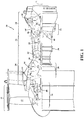
- Alternative engine architectures 200 might include an augmentor section 12, an exhaust duct section 14 and a nozzle section 16 ( Figure 2 ) among other systems or features.
- the fan section 22 drives air along a bypass flowpath and a core flow path for further compression in the compressor section 24.
- the core flow is then communicated into the combustor section 26, where it is burned; then expanded through the turbine section 28.
- turbofan Although depicted as a turbofan in the disclosed non-limiting embodiment, it should be understood that the concepts described herein are not limited to use with turbofans as the teachings may be applied to other types of turbine engine architectures such as turbojets, turboshafts, and three-spool (plus fan) turbofans.
- the engine 20 generally includes a low spool 30 and a high spool 32 mounted for rotation about an engine central longitudinal axis X relative to an engine static structure 36 via several bearing structures 38.
- the low spool 30 generally includes an inner shaft 40 that interconnects a fan 42, a low pressure compressor (“LPC”) 44 and a low pressure turbine (“LPT”) 46.
- the inner shaft 40 drives the fan 42 directly or through a geared architecture 48 to drive the fan 42 at a lower speed than the low spool 30.
- An exemplary reduction transmission is an epicyclic transmission, namely a planetary or star gear system.
- the high spool 32 includes an outer shaft 50 that interconnects a high pressure compressor (“HPC”) 52 and high pressure turbine (“HPT”) 54.
- a combustor 56 is arranged between the high pressure compressor 52 and the high pressure turbine 54.
- the inner shaft 40 and the outer shaft 50 are concentric and rotate about the engine central longitudinal axis X.
- Core airflow is compressed by the LPC 44 then the HPC 52, mixed with the fuel and burned in the combustor 56, then expanded over the HPT 54 and the LPT 46.
- the PT 46 and HPT 54 rotationally drive the respective low spool 30 and high spool 32 in response to the expansion.
- the main engine shafts 40, 50 are supported at a plurality of locations by bearing structures 38 within the static structure 36.
- a shroud assembly 60 within the engine case structure 36 supports a Blade Outer Air Seal (BOAS) assembly 62.
- the BOAS assembly 62 includes a multiple of circumferentially distributed BOAS 64 proximate to a rotor assembly 66 (one shown schematically and partially).
- each BOAS 64 has a main body portion 100 with a leading edge 102, a trailing edge 104, respective circumferential mate face sides 106, 108, an inner face 110 and an outer face 112.
- the BOAS 64 is engaged with the engine static shroud assembly 60 ( Figure 3 ) via a plurality of mounting hooks.
- the exemplary BOAS has a single central forward mounting hook 120, a pair of first and second aft hooks 122, 124, and fore and aft hooks 126, 128 adjacent to the circumferential mate faces side 106 which, when assembled in a circumferential ring array of a plurality of the BOAS 64, interlock with the circumferential mate faces sides 108 of the adjacent BOAS.
- the circumferential ring array of the BOAS 64 encircles an associated blade stage of a gas turbine engine ( Figure 3 ).
- the assembled inner faces 110 thus locally bound an outboard extreme of the core flowpath.
- each BOAS 64 is typically air-cooled via an internal cooling passageway network 130.
- bleed air from the compressor section 24 may be directed through a multiple of inlet passages 134 to the internal cooling passageway network 130 then exhausted through a multiple of outlets passages 136 ( Figure 4 ).
- Example inlet passages 134 may communicate through the outer face 112 and the multiple of outlets passages 136 may communicate through the circumferential mate faces sides 106, 108, the inner face 110, and/or the leading edge 102.
- the cooling requirements and the fluid dynamics of the cooling air change between the leading edge 102 and the trailing edge 104.
- the internal cooling passageway network 130 may include a multiple of distinct internal cooling passage sections 140 (nine shown).
- Each of the internal cooling passage sections 140 generally includes a first plenum section 150, heat exchange cavity core sections 152, and second plenum section 154 ( Figure 7 ).
- the first and second plenum sections 150, 154 are relatively thicker than, and communicate with, the heat exchange cavity core sections 152.
- the core internal cooling passageway network 130 can be reversible.
- the heat exchange cavity core sections 152 may include a multiple of pedestals 160, elongated strips 162 and/or other features to define a tortuous airflow path between the respective first and second plenum sections 150, 154 of a respective section 140 to essentially form a heat exchanger.
- the pedestal type cooling schemes result in a pressure drop, and thus relatively high pressure air will be exiting the outlets passages 136 and into the gap between this BOAS 64 and an adjacent one. In this manner, the relatively high pressure air will purge leakage air away from the gap.
- the heat exchange cavity core sections 152 increase the heat transfer surface area and turbulence to provide more efficient and effective cooling.
- the heat exchange cavity core section 152 is essentially a compact heat exchanger section that is formed relatively thin in a radially outer dimension (into the plane of FIG. 6 ). In this manner, relatively small cooling sections can be provided and can be tailored to the individual challenges of a particular area of the BOAS 64.
- the internal cooling passageway network 130 is formed as a casting core 200 ( Figure 8 ) of a refractory metal of a desired thickness of the first and second plenum sections 150, 154, the heat exchange cavity core sections 152 are then machined to be of a reduced thickness to facilitate heat exchange operation.
- the desired thickness of the first and second plenum sections 150, 154 is generally defined by that which permits a drilling operation, inclusive of a laser drilling operation, into the first and second plenum sections 150, 154 as existing drilling technologies may not be practical for the relatively thin area preferred for the heat exchange cavity core sections 152.
- FIG. 8 actually shows a "mirror" of the cooling passageway network 130 of FIG. 5 .
- Figure 5 includes reference numerals that are identical to those in Figure 8 , even though what is actually shown in Figure 8 is this casting core 200 rather than the actual cooling passages.
- a method 300 for manufacture of the BOAS 64 initially includes forming the casting core 200 ( Figure 8 ) of a refractory metal of a desired thickness to form the first and second plenum sections 150, 154 (step 302). That is, the first and second plenum sections 150, 154 and the heat exchange cavity core sections 152 may be cast or otherwise manufactured to be of a generally consistent thickness.
- the heat exchange cavity core section 152 is machined (step 304). That is, the thickness of the heat exchange cavity core section 152 is reduced.
- the first and second plenum sections 150, 154 may be machined to further control the thickness thereof to achieve a desired more specific thickness tolerance thereof.
- each BOAS 64 may be formed by casting and is typically manufactured of a nickel-base alloy, and more preferably are a nickel-base superalloy (Step 308).
- a nickel-base alloy has more nickel than any other element, and a nickel-base superalloy is a nickel-base alloy that is strengthened by the precipitation of gamma prime or a related phase.
- the casting core 200 is leached out (Step 310) of the material that forms the BOAS 64, to define the internal cooling passageway network 130. That is, the first and second plenum sections 150, 154, and the heat exchange cavity core sections 152, are formed cavities therein to provide the cooling air passages.
- each the first and second plenum sections 150, 154 are of a thickness to be successfully drilled into, the multiple of inlet passages 134 and the multiple of outlets passages 136 are drilled into the desired first and second plenum sections 150, 154 (step 312).
- the passages may be drilled via laser drilling. That is, airflow direction through each internal cooling passage sections 140A-140B may be selected by the drill direction into the desired first and second plenum sections 150, 154.
- outlet passages 136 into the first plenum section 150 may be drilled from the inner face 110 and inlet passages 134 into the second plenum section 154 are drilled from the outer face 112 to define a forward flowing section 140A ( Figure 10 ), or the inlet passages 134 into the first plenum section 150 may be drilled from the outer face 112 and outlet passages 136 into the second plenum section 154 are drilled from the inner face 110 to define an aft flowing section 140B ( Figure 11 ).
- the number and configuration of the inlet passages 134 and the outlets passages 136 may also be modified to match engine changes through a development cycle.
- first and second plenum sections 150, 154 may additionally drilled from the circumferential mate faces sides 106, 108.
- the BOAS 64 advantageously manufactured with the casting core 200 may be readily modified to match engine changes through a development cycle.
- the casting core 200 provides the ability to practically use film cooling with RMC pedestal cores, change flow direction, and inlet and exit configurations.
Landscapes
- Engineering & Computer Science (AREA)
- Mechanical Engineering (AREA)
- General Engineering & Computer Science (AREA)
- Physics & Mathematics (AREA)
- Fluid Mechanics (AREA)
- Turbine Rotor Nozzle Sealing (AREA)
- Molds, Cores, And Manufacturing Methods Thereof (AREA)
Description
- The present invention relates to Blade Outer Air Seals, to methods for manufacturing Blade Outer Air Seals and to casting cores for blade outer air seals (BOAS).
- Gas turbine engines, such as those that power modern commercial and military aircraft, generally include a compressor section to pressurize an airflow, a combustor section to burn a hydrocarbon fuel in the presence of the pressurized air, and a turbine section to extract energy from the resultant combustion gases.
- The combustor section may produce a circumferential temperature pattern referred to as a pattern factor that may result in hot and cold streaks in the turbine section. Stationary components such as Blade Outer Air Seals (BOAS) within the turbine section operate at the local pattern temperature and may be internally cooled by bleed air. For example, there may be an upstream-to-downstream array of cooling passageways within the BOAS. Cooling air may be fed into the array from the outboard side of the BOAS then may exit through outlet ports in the circumferential ends (matefaces) of the BOAS so as to be vented into the adjacent inter-segment region and also exit out the gas path radial surface to create film cooling. The vented air cools adjacent BOAS segments and purges the circumferential gap between adjacent BOAS segments to prevent gas ingestion.
- The BOAS segments may be cast via an investment casting process. In an exemplary casting process, a casting core is used to form the cooling array. The core is located in a die and wax is molded in the die over the core to form a pattern. The pattern is then shelled (e.g., a stuccoing process to form a ceramic shell) and the wax removed from the shell. Metal is then cast in the shell over the core. The shell and core are then destructively removed. After core removal, the core forms the cooling passageway array in the casting. The as-cast passageway may be open in the raw BOAS casting. At least some of the end openings are closed via plug welding, braze pins, or other processes.
- Typically, one type of cooling scheme has been utilized across the BOAS. However, the cooling requirement varies across the BOAS as a pressure ratio between the cooling air and the working air is low at the leading edge, and greater at the trailing edge. Traditionally, casting cores are refractory metal cores (RMCs) that are laser cut from a metallic sheet of constant thickness with inlets and exits passaged defined thereby and formed via bending to define as-cast inlet and exit passages. Although effective, this requires the flow path to be predetermined for a BOAS core during a development cycle since any significant change requires revision to the casting tooling.
-
EP 1905958 A2 discloses a casting core for a blade outer air seal and a blade outer air seal, having the features of the preamble of claims 1 and 4.EP 1213444 A2 discloses a shroud segment for a turbine having multiple heat exchange passages.EP 1541809 A2 discloses a core for use in casting a nozzle guide vane platform.US 2007/0248462 A1 discloses a blade outer air seal with a plurality of cooling circuits.US 5649806 A discloses a blade outer air seal.US 2013/0340966 A1 discloses a blade outer air seal hybrid casting core. - From one aspect, the invention provides a casting core for a Blade Outer Air Seal as set forth in claim 1.
- The invention also provides a Blade Outer Air Seal as set forth in claim 4.
- The invention further provides a method of manufacturing a Blade Outer Air Seal as set forth in claim 9.
- Features of embodiments are recited in the dependent claims.
- Various features will become apparent to those skilled in the art from the following detailed description of the disclosed non-limiting embodiments. The drawings that accompany the detailed description can be briefly described as follows:
-
Figure 1 is a schematic cross-section of an example gas turbine engine architecture; -
Figure 2 is a schematic cross-section of another example gas turbine engine architecture; -
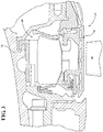
Figure 3 is an enlarged schematic cross-section of an engine turbine section; -
Figure 4 is a perspective view of a BOAS; -
Figure 5 is a perspective view of BOAS illustrating a cooling passageway; -
Figure 6 is a plan view of the cooling passageway network of the BOAS; -
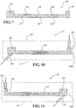
Figure 7 is a sectional view of a section of the cooling passage network; -
Figure 8 is a perspective view of the casting cores; -
Figure 9 is a method of manufacturing the cooling passage network; -
Figure 10 is a sectional view of one section of the cooling network drilled for a forward airflow path direction; and -
Figure 11 is a section view of one section of the cooling network drilled for an aft airflow path direction. -
Figure 1 schematically illustrates agas turbine engine 20. Thegas turbine engine 20 is disclosed herein as a two-spool turbo fan that generally incorporates afan section 22, acompressor section 24, acombustor section 26 and aturbine section 28.Alternative engine architectures 200 might include anaugmentor section 12, anexhaust duct section 14 and a nozzle section 16 (Figure 2 ) among other systems or features. Thefan section 22 drives air along a bypass flowpath and a core flow path for further compression in thecompressor section 24. The core flow is then communicated into thecombustor section 26, where it is burned; then expanded through theturbine section 28. Although depicted as a turbofan in the disclosed non-limiting embodiment, it should be understood that the concepts described herein are not limited to use with turbofans as the teachings may be applied to other types of turbine engine architectures such as turbojets, turboshafts, and three-spool (plus fan) turbofans. - The
engine 20 generally includes alow spool 30 and ahigh spool 32 mounted for rotation about an engine central longitudinal axis X relative to an enginestatic structure 36 viaseveral bearing structures 38. Thelow spool 30 generally includes aninner shaft 40 that interconnects afan 42, a low pressure compressor ("LPC") 44 and a low pressure turbine ("LPT") 46. Theinner shaft 40 drives thefan 42 directly or through a gearedarchitecture 48 to drive thefan 42 at a lower speed than thelow spool 30. An exemplary reduction transmission is an epicyclic transmission, namely a planetary or star gear system. - The
high spool 32 includes anouter shaft 50 that interconnects a high pressure compressor ("HPC") 52 and high pressure turbine ("HPT") 54. Acombustor 56 is arranged between thehigh pressure compressor 52 and thehigh pressure turbine 54. Theinner shaft 40 and theouter shaft 50 are concentric and rotate about the engine central longitudinal axis X. - Core airflow is compressed by the
LPC 44 then the HPC 52, mixed with the fuel and burned in thecombustor 56, then expanded over the HPT 54 and theLPT 46. The PT 46 and HPT 54 rotationally drive the respectivelow spool 30 andhigh spool 32 in response to the expansion. Themain engine shafts structures 38 within thestatic structure 36. - With reference to
Figure 3 , an enlarged schematic view of a portion of theturbine section 28 is shown by way of example; however, other engine sections will also benefit herefrom. A shroud assembly 60 within theengine case structure 36 supports a Blade Outer Air Seal (BOAS)assembly 62. TheBOAS assembly 62 includes a multiple of circumferentially distributedBOAS 64 proximate to a rotor assembly 66 (one shown schematically and partially). - With reference to
Figure 4 , eachBOAS 64 has amain body portion 100 with aleading edge 102, a trailingedge 104, respective circumferential mate face sides 106, 108, aninner face 110 and anouter face 112. TheBOAS 64 is engaged with the engine static shroud assembly 60 (Figure 3 ) via a plurality of mounting hooks. The exemplary BOAS has a single centralforward mounting hook 120, a pair of first and second aft hooks 122, 124, and fore andaft hooks side 106 which, when assembled in a circumferential ring array of a plurality of theBOAS 64, interlock with the circumferential mate facessides 108 of the adjacent BOAS. The circumferential ring array of theBOAS 64 encircles an associated blade stage of a gas turbine engine (Figure 3 ). The assembledinner faces 110 thus locally bound an outboard extreme of the core flowpath. - With reference to
Figure 5 , eachBOAS 64 is typically air-cooled via an internalcooling passageway network 130. For example, bleed air from thecompressor section 24 may be directed through a multiple ofinlet passages 134 to the internalcooling passageway network 130 then exhausted through a multiple of outlets passages 136 (Figure 4 ).Example inlet passages 134 may communicate through theouter face 112 and the multiple ofoutlets passages 136 may communicate through the circumferential mate facessides inner face 110, and/or theleading edge 102. As will be appreciated, the cooling requirements and the fluid dynamics of the cooling air change between theleading edge 102 and the trailingedge 104. - With reference to
Figure 6 , the internalcooling passageway network 130 may include a multiple of distinct internal cooling passage sections 140 (nine shown). Each of the internalcooling passage sections 140 generally includes afirst plenum section 150, heat exchangecavity core sections 152, and second plenum section 154 (Figure 7 ). The first andsecond plenum sections cavity core sections 152. It should be appreciated that the core internalcooling passageway network 130 can be reversible. The heat exchangecavity core sections 152 may include a multiple ofpedestals 160,elongated strips 162 and/or other features to define a tortuous airflow path between the respective first andsecond plenum sections respective section 140 to essentially form a heat exchanger. - The pedestal type cooling schemes result in a pressure drop, and thus relatively high pressure air will be exiting the
outlets passages 136 and into the gap between thisBOAS 64 and an adjacent one. In this manner, the relatively high pressure air will purge leakage air away from the gap. The heat exchangecavity core sections 152 increase the heat transfer surface area and turbulence to provide more efficient and effective cooling. The heat exchangecavity core section 152 is essentially a compact heat exchanger section that is formed relatively thin in a radially outer dimension (into the plane ofFIG. 6 ). In this manner, relatively small cooling sections can be provided and can be tailored to the individual challenges of a particular area of theBOAS 64. - The internal
cooling passageway network 130 is formed as a casting core 200 (Figure 8 ) of a refractory metal of a desired thickness of the first andsecond plenum sections cavity core sections 152 are then machined to be of a reduced thickness to facilitate heat exchange operation. The desired thickness of the first andsecond plenum sections second plenum sections cavity core sections 152. It should be appreciated thatFIG. 8 actually shows a "mirror" of the coolingpassageway network 130 ofFIG. 5 . Notably,Figure 5 includes reference numerals that are identical to those inFigure 8 , even though what is actually shown inFigure 8 is thiscasting core 200 rather than the actual cooling passages. - With reference to
Figure 9 , amethod 300 for manufacture of theBOAS 64 initially includes forming the casting core 200 (Figure 8 ) of a refractory metal of a desired thickness to form the first andsecond plenum sections 150, 154 (step 302). That is, the first andsecond plenum sections cavity core sections 152 may be cast or otherwise manufactured to be of a generally consistent thickness. - Next, to form the thickness differential between the first and
second plenum sections cavity core sections 152, the heat exchangecavity core section 152 is machined (step 304). That is, the thickness of the heat exchangecavity core section 152 is reduced. Alternatively, the first andsecond plenum sections - Next, the
casting core 200 is located within a mold to form the BOAS 64 (Step 306). To resist the high temperature stress environment in the gas path of a turbine engine, eachBOAS 64 may be formed by casting and is typically manufactured of a nickel-base alloy, and more preferably are a nickel-base superalloy (Step 308). A nickel-base alloy has more nickel than any other element, and a nickel-base superalloy is a nickel-base alloy that is strengthened by the precipitation of gamma prime or a related phase. - Once material has formed around this the casting core 200 (Step 308), the
casting core 200 is leached out (Step 310) of the material that forms theBOAS 64, to define the internalcooling passageway network 130. That is, the first andsecond plenum sections cavity core sections 152, are formed cavities therein to provide the cooling air passages. - Next, as each the first and
second plenum sections inlet passages 134 and the multiple ofoutlets passages 136 are drilled into the desired first andsecond plenum sections 150, 154 (step 312). It should be appreciated that the passages may be drilled via laser drilling. That is, airflow direction through each internalcooling passage sections 140A-140B may be selected by the drill direction into the desired first andsecond plenum sections outlet passages 136 into thefirst plenum section 150 may be drilled from theinner face 110 andinlet passages 134 into thesecond plenum section 154 are drilled from theouter face 112 to define a forward flowingsection 140A (Figure 10 ), or theinlet passages 134 into thefirst plenum section 150 may be drilled from theouter face 112 andoutlet passages 136 into thesecond plenum section 154 are drilled from theinner face 110 to define anaft flowing section 140B (Figure 11 ). The number and configuration of theinlet passages 134 and theoutlets passages 136 may also be modified to match engine changes through a development cycle. - Since the core is axially flowing and the inlets and exits are drilled - rather than as traditionally formed by the casting core - a change in flow direction, inlet and exit passageway configurations, as well as numbers thereof, is readily accommodated. The first and
second plenum sections sides - The
BOAS 64 advantageously manufactured with thecasting core 200 may be readily modified to match engine changes through a development cycle. Thecasting core 200 provides the ability to practically use film cooling with RMC pedestal cores, change flow direction, and inlet and exit configurations. - The use of the terms "a," "an," "the," and similar references in the context of description (especially in the context of the following claims) are to be construed to cover both the singular and the plural, unless otherwise indicated herein or specifically contradicted by context. The modifier "about" used in connection with a quantity is inclusive of the stated value and has the meaning dictated by the context (e.g., it includes the degree of error associated with measurement of the particular quantity). All ranges disclosed herein are inclusive of the endpoints, and the endpoints are independently combinable with each other. It should be appreciated that relative positional terms such as "forward," "aft," "upper," "lower," "above," "below," and the like are with reference to normal operational attitude and should not be considered otherwise limiting.
- Although the different non-limiting embodiments have specific illustrated components, the embodiments of this invention are not limited to those particular combinations. It is possible to use some of the components or features from any of the non-limiting embodiments in combination with features or components from any of the other non-limiting embodiments.
- It should be appreciated that like reference numerals identify corresponding or similar elements throughout the several drawings. It should also be appreciated that although a particular component arrangement is disclosed in the illustrated embodiment, other arrangements will benefit herefrom.
- Although particular step sequences are shown, described, and claimed, it should be understood that steps may be performed in any order, separated or combined unless otherwise indicated and will still benefit from the present disclosure.
- The foregoing description is exemplary rather than defined by the limitations within. Various non-limiting embodiments are disclosed herein, however, one of ordinary skill in the art would recognize that various modifications and variations in light of the above teachings will fall within the scope of the appended claims. It is therefore to be understood that within the scope of the appended claims, the disclosure may be practiced other than as specifically described. For that reason the appended claims should be studied to determine true scope and content.
Claims (10)
- A casting core (200) for a Blade Outer Air Seal, comprising:a first plenum-forming section (150);a second plenum-forming section (154); anda heat exchange cavity-forming section (152) in communication with said first plenum-forming section (150) and said second plenum-forming section (154);characterized in thatsaid first plenum-forming section (150) and said second plenum-forming section (154) are each of a radial thickness greater than a radial thickness of said heat exchange cavity-forming section (152).
- The casting core as recited in claim 1, wherein said heat exchange cavity-forming section (152) includes features for forming a multiple of pedestals (160) defining a tortuous airflow path.
- The casting core as recited in claim 1 or 2, wherein said heat exchange cavity-forming section (152) includes features for forming a multiple of elongated strips (162) defining a tortuous airflow path.
- A Blade Outer Air Seal (64), comprising:a main body portion (100) having an inner face (110) and an outer face (112);a first plenum section (150);a second plenum section (154); anda heat exchange cavity core section (152) in communication with said first plenum section (150) and said second plenum section (154);characterized in that:
said first plenum section (150) and said second plenum section (154) each has a respective radial thickness greater than a radial thickness of said heat exchange cavity core section (152); and bya first multiple of passages (134) drilled into the first plenum section (150) from the outer face (112); anda second multiple of passages (136) drilled into the second plenum section (150) from the inner face (110). - The Blade Outer Air Seal as recited in claim 4, wherein the first multiple of passages (134) are inlet passages (134) to said first plenum through the outer face (112).
- The Blade Outer Air Seal as recited in claim 4 or 5, wherein the second multiple of passages (136) are exit passages (136) from said second plenum section (154) through the inner face (110).
- The Blade Outer Air Seal as recited in any of claims 4 to 6, wherein said heat exchange cavity core section (152) includes a multiple of pedestals (160).
- The Blade Outer Air Seal as recited in any of claims 4 to 7, wherein said heat exchange cavity core section (152) includes a multiple of elongated strips (162).
- A method of manufacturing a Blade Outer Air Seal, comprising:forming a casting core (200) as recited in any of claims 1 to 3, wherein said heat exchange cavity-forming section (152) is formed by machining the heat exchange cavity-forming section (152) of the casting core (200) relative to the first and second plenum forming-sections (150, 154);locating said casting core (200) within a mold;casting a Blade Outer Air Seal in said mold;leaching out the casting core (200) to form a Blade Outer Air Seal comprising:a main body portion (100) having an inner face (110) and an outer face (112);a first plenum section (150);a second plenum section (154); anda heat exchange cavity core section (152) in communication with said first plenum section (150) and said second plenum section (154), said first plenum section (150) and said second plenum section (154) each having a respective radial thickness greater than a radial thickness of said heat exchange cavity core section (152); anddrilling a first multiple of passages (134) into the first plenum section (150) from the outer face (112) and a second multiple of passages (136) into the second plenum section (154) from the inner face (110).
- The Blade Outer Air Seal or method as recited in any of claims 4 to 9, wherein the second multiple of passages (136) are defined at an angle with respect to the inner face (110).
Applications Claiming Priority (1)
| Application Number | Priority Date | Filing Date | Title |
|---|---|---|---|
| US201462091880P | 2014-12-15 | 2014-12-15 |
Publications (3)
| Publication Number | Publication Date |
|---|---|
| EP3034808A2 EP3034808A2 (en) | 2016-06-22 |
| EP3034808A3 EP3034808A3 (en) | 2016-08-24 |
| EP3034808B1 true EP3034808B1 (en) | 2021-12-01 |
Family
ID=54325451
Family Applications (1)
| Application Number | Title | Priority Date | Filing Date |
|---|---|---|---|
| EP15189830.1A Active EP3034808B1 (en) | 2014-12-15 | 2015-10-14 | Casting core for blade outer air seal, blade outer air seal and corresponding manufacturing method |
Country Status (2)
| Country | Link |
|---|---|
| US (1) | US10329934B2 (en) |
| EP (1) | EP3034808B1 (en) |
Families Citing this family (14)
| Publication number | Priority date | Publication date | Assignee | Title |
|---|---|---|---|---|
| EP2910765B1 (en) * | 2014-02-21 | 2017-10-25 | Rolls-Royce Corporation | Single phase micro/mini channel heat exchangers for gas turbine intercooling and corresponding method |
| EP2910887B1 (en) | 2014-02-21 | 2019-06-26 | Rolls-Royce Corporation | Microchannel heat exchangers for gas turbine intercooling and condensing as well as corresponding method |
| CN107429569B (en) * | 2015-04-03 | 2019-09-24 | 西门子公司 | Turbine bucket trailing edge with low flow framed channels |
| US10713537B2 (en) * | 2017-07-01 | 2020-07-14 | Algolux Inc. | Method and apparatus for joint image processing and perception |
| US10502093B2 (en) * | 2017-12-13 | 2019-12-10 | Pratt & Whitney Canada Corp. | Turbine shroud cooling |
| US10570773B2 (en) | 2017-12-13 | 2020-02-25 | Pratt & Whitney Canada Corp. | Turbine shroud cooling |
| US11274569B2 (en) | 2017-12-13 | 2022-03-15 | Pratt & Whitney Canada Corp. | Turbine shroud cooling |
| US10533454B2 (en) | 2017-12-13 | 2020-01-14 | Pratt & Whitney Canada Corp. | Turbine shroud cooling |
| GB201803326D0 (en) * | 2018-03-01 | 2018-04-18 | Rolls Royce Plc | A core for an investment casting process |
| US11268402B2 (en) * | 2018-04-11 | 2022-03-08 | Raytheon Technologies Corporation | Blade outer air seal cooling fin |
| US11333023B2 (en) | 2018-11-09 | 2022-05-17 | Raytheon Technologies Corporation | Article having cooling passage network with inter-row sub-passages |
| US11619136B2 (en) * | 2019-06-07 | 2023-04-04 | Raytheon Technologies Corporation | Fatigue resistant blade outer air seal |
| US10961862B2 (en) * | 2019-06-07 | 2021-03-30 | Raytheon Technologies Corporation | Fatigue resistant blade outer air seal |
| US11365645B2 (en) | 2020-10-07 | 2022-06-21 | Pratt & Whitney Canada Corp. | Turbine shroud cooling |
Family Cites Families (35)
| Publication number | Priority date | Publication date | Assignee | Title |
|---|---|---|---|---|
| US4526226A (en) | 1981-08-31 | 1985-07-02 | General Electric Company | Multiple-impingement cooled structure |
| US5649806A (en) * | 1993-11-22 | 1997-07-22 | United Technologies Corporation | Enhanced film cooling slot for turbine blade outer air seals |
| US5486090A (en) | 1994-03-30 | 1996-01-23 | United Technologies Corporation | Turbine shroud segment with serpentine cooling channels |
| US5584651A (en) * | 1994-10-31 | 1996-12-17 | General Electric Company | Cooled shroud |
| US5609469A (en) | 1995-11-22 | 1997-03-11 | United Technologies Corporation | Rotor assembly shroud |
| US5993150A (en) | 1998-01-16 | 1999-11-30 | General Electric Company | Dual cooled shroud |
| US6146091A (en) | 1998-03-03 | 2000-11-14 | Mitsubishi Heavy Industries, Ltd. | Gas turbine cooling structure |
| GB0029337D0 (en) | 2000-12-01 | 2001-01-17 | Rolls Royce Plc | A seal segment for a turbine |
| EP1245792A1 (en) | 2001-03-30 | 2002-10-02 | Siemens Aktiengesellschaft | Coolable turbine shroud and process of manufacturing the shroud |
| US6705831B2 (en) | 2002-06-19 | 2004-03-16 | United Technologies Corporation | Linked, manufacturable, non-plugging microcircuits |
| US7033138B2 (en) | 2002-09-06 | 2006-04-25 | Mitsubishi Heavy Industries, Ltd. | Ring segment of gas turbine |
| FR2857406B1 (en) | 2003-07-10 | 2005-09-30 | Snecma Moteurs | COOLING THE TURBINE RINGS |
| US6905302B2 (en) * | 2003-09-17 | 2005-06-14 | General Electric Company | Network cooled coated wall |
| GB0328952D0 (en) | 2003-12-12 | 2004-01-14 | Rolls Royce Plc | Nozzle guide vanes |
| US7775053B2 (en) | 2004-09-20 | 2010-08-17 | United Technologies Corporation | Heat transfer augmentation in a compact heat exchanger pedestal array |
| US7306424B2 (en) | 2004-12-29 | 2007-12-11 | United Technologies Corporation | Blade outer seal with micro axial flow cooling system |
| US7621719B2 (en) | 2005-09-30 | 2009-11-24 | United Technologies Corporation | Multiple cooling schemes for turbine blade outer air seal |
| US7334985B2 (en) | 2005-10-11 | 2008-02-26 | United Technologies Corporation | Shroud with aero-effective cooling |
| US7763356B2 (en) * | 2006-03-13 | 2010-07-27 | United Technologies Corporation | Bond coating and thermal barrier compositions, processes for applying both, and their coated articles |
| US7686068B2 (en) | 2006-08-10 | 2010-03-30 | United Technologies Corporation | Blade outer air seal cores and manufacture methods |
| US7650926B2 (en) | 2006-09-28 | 2010-01-26 | United Technologies Corporation | Blade outer air seals, cores, and manufacture methods |
| US7665961B2 (en) | 2006-11-28 | 2010-02-23 | United Technologies Corporation | Turbine outer air seal |
| US8128348B2 (en) | 2007-09-26 | 2012-03-06 | United Technologies Corporation | Segmented cooling air cavity for turbine component |
| US7874792B2 (en) | 2007-10-01 | 2011-01-25 | United Technologies Corporation | Blade outer air seals, cores, and manufacture methods |
| US8128349B2 (en) | 2007-10-17 | 2012-03-06 | United Technologies Corp. | Gas turbine engines and related systems involving blade outer air seals |
| US8206092B2 (en) | 2007-12-05 | 2012-06-26 | United Technologies Corp. | Gas turbine engines and related systems involving blade outer air seals |
| US8534993B2 (en) | 2008-02-13 | 2013-09-17 | United Technologies Corp. | Gas turbine engines and related systems involving blade outer air seals |
| US8177492B2 (en) | 2008-03-04 | 2012-05-15 | United Technologies Corporation | Passage obstruction for improved inlet coolant filling |
| US8128366B2 (en) | 2008-06-06 | 2012-03-06 | United Technologies Corporation | Counter-vortex film cooling hole design |
| US8317461B2 (en) | 2008-08-27 | 2012-11-27 | United Technologies Corporation | Gas turbine engine component having dual flow passage cooling chamber formed by single core |
| US8529201B2 (en) | 2009-12-17 | 2013-09-10 | United Technologies Corporation | Blade outer air seal formed of stacked panels |
| US8556575B2 (en) | 2010-03-26 | 2013-10-15 | United Technologies Corporation | Blade outer seal for a gas turbine engine |
| US8535783B2 (en) | 2010-06-08 | 2013-09-17 | United Technologies Corporation | Ceramic coating systems and methods |
| GB201115354D0 (en) * | 2011-09-06 | 2011-10-19 | Rolls Royce Plc | Method of drilling through a wall of a hollow component |
| US20130340966A1 (en) * | 2012-06-21 | 2013-12-26 | United Technologies Corporation | Blade outer air seal hybrid casting core |
-
2015
- 2015-10-12 US US14/880,403 patent/US10329934B2/en active Active
- 2015-10-14 EP EP15189830.1A patent/EP3034808B1/en active Active
Non-Patent Citations (1)
| Title |
|---|
| None * |
Also Published As
| Publication number | Publication date |
|---|---|
| US20160169016A1 (en) | 2016-06-16 |
| US10329934B2 (en) | 2019-06-25 |
| EP3034808A2 (en) | 2016-06-22 |
| EP3034808A3 (en) | 2016-08-24 |
Similar Documents
| Publication | Publication Date | Title |
|---|---|---|
| US10329934B2 (en) | Reversible flow blade outer air seal | |
| US11059093B2 (en) | Additively manufactured core for use in casting an internal cooling circuit of a gas turbine engine component | |
| EP2867472B1 (en) | Turbine vane | |
| US7625172B2 (en) | Vane platform cooling | |
| US11035236B2 (en) | Baffle for a component of a gas turbine engine | |
| EP2565383B1 (en) | Airfoil with cooling passage | |
| EP2900962B1 (en) | Gas turbine engine airfoil with vane platform cooling passage | |
| US20180230832A1 (en) | Cooled blisk for gas turbine engine | |
| EP3214274B1 (en) | Encapsulated cooling for turbine shrouds | |
| EP3054094B1 (en) | Gas turbine engine turbine vane baffle and serpentine cooling passage | |
| EP2900967A2 (en) | Airfoil with variable trip strip height | |
| EP3498979B1 (en) | Cooled airfoil | |
| EP2956257B1 (en) | Gas turbine engine component cooling passage and space eating core | |
| US11828193B2 (en) | Vane core assemblies and methods | |
| US12497896B2 (en) | Airfoil assembly with platform film holes | |
| EP3418495B1 (en) | Gaspath component including minicore plenums | |
| EP3901418A1 (en) | Feather seal mateface cooling pockets | |
| EP4656844A2 (en) | Components for a gas turbine engine and gas turbine engine | |
| EP4353950A2 (en) | Blade outer air seal with cooling channels |
Legal Events
| Date | Code | Title | Description |
|---|---|---|---|
| PUAI | Public reference made under article 153(3) epc to a published international application that has entered the european phase |
Free format text: ORIGINAL CODE: 0009012 |
|
| AK | Designated contracting states |
Kind code of ref document: A2 Designated state(s): AL AT BE BG CH CY CZ DE DK EE ES FI FR GB GR HR HU IE IS IT LI LT LU LV MC MK MT NL NO PL PT RO RS SE SI SK SM TR |
|
| AX | Request for extension of the european patent |
Extension state: BA ME |
|
| PUAL | Search report despatched |
Free format text: ORIGINAL CODE: 0009013 |
|
| AK | Designated contracting states |
Kind code of ref document: A3 Designated state(s): AL AT BE BG CH CY CZ DE DK EE ES FI FR GB GR HR HU IE IS IT LI LT LU LV MC MK MT NL NO PL PT RO RS SE SI SK SM TR |
|
| AX | Request for extension of the european patent |
Extension state: BA ME |
|
| RIC1 | Information provided on ipc code assigned before grant |
Ipc: F01D 11/12 20060101ALI20160719BHEP Ipc: F01D 11/08 20060101AFI20160719BHEP Ipc: B22C 9/10 20060101ALI20160719BHEP Ipc: F01D 25/24 20060101ALI20160719BHEP |
|
| RAP1 | Party data changed (applicant data changed or rights of an application transferred) |
Owner name: UNITED TECHNOLOGIES CORPORATION |
|
| STAA | Information on the status of an ep patent application or granted ep patent |
Free format text: STATUS: REQUEST FOR EXAMINATION WAS MADE |
|
| 17P | Request for examination filed |
Effective date: 20170224 |
|
| RBV | Designated contracting states (corrected) |
Designated state(s): AL AT BE BG CH CY CZ DE DK EE ES FI FR GB GR HR HU IE IS IT LI LT LU LV MC MK MT NL NO PL PT RO RS SE SI SK SM TR |
|
| STAA | Information on the status of an ep patent application or granted ep patent |
Free format text: STATUS: EXAMINATION IS IN PROGRESS |
|
| 17Q | First examination report despatched |
Effective date: 20201008 |
|
| RAP1 | Party data changed (applicant data changed or rights of an application transferred) |
Owner name: RAYTHEON TECHNOLOGIES CORPORATION |
|
| GRAP | Despatch of communication of intention to grant a patent |
Free format text: ORIGINAL CODE: EPIDOSNIGR1 |
|
| STAA | Information on the status of an ep patent application or granted ep patent |
Free format text: STATUS: GRANT OF PATENT IS INTENDED |
|
| INTG | Intention to grant announced |
Effective date: 20210510 |
|
| GRAS | Grant fee paid |
Free format text: ORIGINAL CODE: EPIDOSNIGR3 |
|
| GRAA | (expected) grant |
Free format text: ORIGINAL CODE: 0009210 |
|
| STAA | Information on the status of an ep patent application or granted ep patent |
Free format text: STATUS: THE PATENT HAS BEEN GRANTED |
|
| AK | Designated contracting states |
Kind code of ref document: B1 Designated state(s): AL AT BE BG CH CY CZ DE DK EE ES FI FR GB GR HR HU IE IS IT LI LT LU LV MC MK MT NL NO PL PT RO RS SE SI SK SM TR |
|
| REG | Reference to a national code |
Ref country code: GB Ref legal event code: FG4D |
|
| REG | Reference to a national code |
Ref country code: AT Ref legal event code: REF Ref document number: 1451948 Country of ref document: AT Kind code of ref document: T Effective date: 20211215 Ref country code: CH Ref legal event code: EP |
|
| REG | Reference to a national code |
Ref country code: IE Ref legal event code: FG4D |
|
| REG | Reference to a national code |
Ref country code: DE Ref legal event code: R096 Ref document number: 602015075372 Country of ref document: DE |
|
| REG | Reference to a national code |
Ref country code: LT Ref legal event code: MG9D |
|
| REG | Reference to a national code |
Ref country code: NL Ref legal event code: MP Effective date: 20211201 |
|
| REG | Reference to a national code |
Ref country code: AT Ref legal event code: MK05 Ref document number: 1451948 Country of ref document: AT Kind code of ref document: T Effective date: 20211201 |
|
| PG25 | Lapsed in a contracting state [announced via postgrant information from national office to epo] |
Ref country code: RS Free format text: LAPSE BECAUSE OF FAILURE TO SUBMIT A TRANSLATION OF THE DESCRIPTION OR TO PAY THE FEE WITHIN THE PRESCRIBED TIME-LIMIT Effective date: 20211201 Ref country code: LT Free format text: LAPSE BECAUSE OF FAILURE TO SUBMIT A TRANSLATION OF THE DESCRIPTION OR TO PAY THE FEE WITHIN THE PRESCRIBED TIME-LIMIT Effective date: 20211201 Ref country code: FI Free format text: LAPSE BECAUSE OF FAILURE TO SUBMIT A TRANSLATION OF THE DESCRIPTION OR TO PAY THE FEE WITHIN THE PRESCRIBED TIME-LIMIT Effective date: 20211201 Ref country code: BG Free format text: LAPSE BECAUSE OF FAILURE TO SUBMIT A TRANSLATION OF THE DESCRIPTION OR TO PAY THE FEE WITHIN THE PRESCRIBED TIME-LIMIT Effective date: 20220301 Ref country code: AT Free format text: LAPSE BECAUSE OF FAILURE TO SUBMIT A TRANSLATION OF THE DESCRIPTION OR TO PAY THE FEE WITHIN THE PRESCRIBED TIME-LIMIT Effective date: 20211201 |
|
| PG25 | Lapsed in a contracting state [announced via postgrant information from national office to epo] |
Ref country code: SE Free format text: LAPSE BECAUSE OF FAILURE TO SUBMIT A TRANSLATION OF THE DESCRIPTION OR TO PAY THE FEE WITHIN THE PRESCRIBED TIME-LIMIT Effective date: 20211201 Ref country code: PL Free format text: LAPSE BECAUSE OF FAILURE TO SUBMIT A TRANSLATION OF THE DESCRIPTION OR TO PAY THE FEE WITHIN THE PRESCRIBED TIME-LIMIT Effective date: 20211201 Ref country code: NO Free format text: LAPSE BECAUSE OF FAILURE TO SUBMIT A TRANSLATION OF THE DESCRIPTION OR TO PAY THE FEE WITHIN THE PRESCRIBED TIME-LIMIT Effective date: 20220301 Ref country code: LV Free format text: LAPSE BECAUSE OF FAILURE TO SUBMIT A TRANSLATION OF THE DESCRIPTION OR TO PAY THE FEE WITHIN THE PRESCRIBED TIME-LIMIT Effective date: 20211201 Ref country code: HR Free format text: LAPSE BECAUSE OF FAILURE TO SUBMIT A TRANSLATION OF THE DESCRIPTION OR TO PAY THE FEE WITHIN THE PRESCRIBED TIME-LIMIT Effective date: 20211201 Ref country code: GR Free format text: LAPSE BECAUSE OF FAILURE TO SUBMIT A TRANSLATION OF THE DESCRIPTION OR TO PAY THE FEE WITHIN THE PRESCRIBED TIME-LIMIT Effective date: 20220302 Ref country code: ES Free format text: LAPSE BECAUSE OF FAILURE TO SUBMIT A TRANSLATION OF THE DESCRIPTION OR TO PAY THE FEE WITHIN THE PRESCRIBED TIME-LIMIT Effective date: 20211201 |
|
| PG25 | Lapsed in a contracting state [announced via postgrant information from national office to epo] |
Ref country code: NL Free format text: LAPSE BECAUSE OF FAILURE TO SUBMIT A TRANSLATION OF THE DESCRIPTION OR TO PAY THE FEE WITHIN THE PRESCRIBED TIME-LIMIT Effective date: 20211201 |
|
| PG25 | Lapsed in a contracting state [announced via postgrant information from national office to epo] |
Ref country code: SM Free format text: LAPSE BECAUSE OF FAILURE TO SUBMIT A TRANSLATION OF THE DESCRIPTION OR TO PAY THE FEE WITHIN THE PRESCRIBED TIME-LIMIT Effective date: 20211201 Ref country code: SK Free format text: LAPSE BECAUSE OF FAILURE TO SUBMIT A TRANSLATION OF THE DESCRIPTION OR TO PAY THE FEE WITHIN THE PRESCRIBED TIME-LIMIT Effective date: 20211201 Ref country code: RO Free format text: LAPSE BECAUSE OF FAILURE TO SUBMIT A TRANSLATION OF THE DESCRIPTION OR TO PAY THE FEE WITHIN THE PRESCRIBED TIME-LIMIT Effective date: 20211201 Ref country code: PT Free format text: LAPSE BECAUSE OF FAILURE TO SUBMIT A TRANSLATION OF THE DESCRIPTION OR TO PAY THE FEE WITHIN THE PRESCRIBED TIME-LIMIT Effective date: 20220401 Ref country code: EE Free format text: LAPSE BECAUSE OF FAILURE TO SUBMIT A TRANSLATION OF THE DESCRIPTION OR TO PAY THE FEE WITHIN THE PRESCRIBED TIME-LIMIT Effective date: 20211201 Ref country code: CZ Free format text: LAPSE BECAUSE OF FAILURE TO SUBMIT A TRANSLATION OF THE DESCRIPTION OR TO PAY THE FEE WITHIN THE PRESCRIBED TIME-LIMIT Effective date: 20211201 |
|
| REG | Reference to a national code |
Ref country code: DE Ref legal event code: R097 Ref document number: 602015075372 Country of ref document: DE |
|
| PG25 | Lapsed in a contracting state [announced via postgrant information from national office to epo] |
Ref country code: IS Free format text: LAPSE BECAUSE OF FAILURE TO SUBMIT A TRANSLATION OF THE DESCRIPTION OR TO PAY THE FEE WITHIN THE PRESCRIBED TIME-LIMIT Effective date: 20220401 |
|
| PLBE | No opposition filed within time limit |
Free format text: ORIGINAL CODE: 0009261 |
|
| STAA | Information on the status of an ep patent application or granted ep patent |
Free format text: STATUS: NO OPPOSITION FILED WITHIN TIME LIMIT |
|
| PG25 | Lapsed in a contracting state [announced via postgrant information from national office to epo] |
Ref country code: DK Free format text: LAPSE BECAUSE OF FAILURE TO SUBMIT A TRANSLATION OF THE DESCRIPTION OR TO PAY THE FEE WITHIN THE PRESCRIBED TIME-LIMIT Effective date: 20211201 Ref country code: AL Free format text: LAPSE BECAUSE OF FAILURE TO SUBMIT A TRANSLATION OF THE DESCRIPTION OR TO PAY THE FEE WITHIN THE PRESCRIBED TIME-LIMIT Effective date: 20211201 |
|
| 26N | No opposition filed |
Effective date: 20220902 |
|
| PG25 | Lapsed in a contracting state [announced via postgrant information from national office to epo] |
Ref country code: SI Free format text: LAPSE BECAUSE OF FAILURE TO SUBMIT A TRANSLATION OF THE DESCRIPTION OR TO PAY THE FEE WITHIN THE PRESCRIBED TIME-LIMIT Effective date: 20211201 |
|
| PG25 | Lapsed in a contracting state [announced via postgrant information from national office to epo] |
Ref country code: MC Free format text: LAPSE BECAUSE OF FAILURE TO SUBMIT A TRANSLATION OF THE DESCRIPTION OR TO PAY THE FEE WITHIN THE PRESCRIBED TIME-LIMIT Effective date: 20211201 Ref country code: IT Free format text: LAPSE BECAUSE OF FAILURE TO SUBMIT A TRANSLATION OF THE DESCRIPTION OR TO PAY THE FEE WITHIN THE PRESCRIBED TIME-LIMIT Effective date: 20211201 |
|
| REG | Reference to a national code |
Ref country code: CH Ref legal event code: PL |
|
| REG | Reference to a national code |
Ref country code: BE Ref legal event code: MM Effective date: 20221031 |
|
| P01 | Opt-out of the competence of the unified patent court (upc) registered |
Effective date: 20230520 |
|
| PG25 | Lapsed in a contracting state [announced via postgrant information from national office to epo] |
Ref country code: LU Free format text: LAPSE BECAUSE OF NON-PAYMENT OF DUE FEES Effective date: 20221014 |
|
| PG25 | Lapsed in a contracting state [announced via postgrant information from national office to epo] |
Ref country code: LI Free format text: LAPSE BECAUSE OF NON-PAYMENT OF DUE FEES Effective date: 20221031 Ref country code: CH Free format text: LAPSE BECAUSE OF NON-PAYMENT OF DUE FEES Effective date: 20221031 |
|
| PG25 | Lapsed in a contracting state [announced via postgrant information from national office to epo] |
Ref country code: BE Free format text: LAPSE BECAUSE OF NON-PAYMENT OF DUE FEES Effective date: 20221031 |
|
| PG25 | Lapsed in a contracting state [announced via postgrant information from national office to epo] |
Ref country code: IE Free format text: LAPSE BECAUSE OF NON-PAYMENT OF DUE FEES Effective date: 20221014 |
|
| PG25 | Lapsed in a contracting state [announced via postgrant information from national office to epo] |
Ref country code: HU Free format text: LAPSE BECAUSE OF FAILURE TO SUBMIT A TRANSLATION OF THE DESCRIPTION OR TO PAY THE FEE WITHIN THE PRESCRIBED TIME-LIMIT; INVALID AB INITIO Effective date: 20151014 |
|
| PG25 | Lapsed in a contracting state [announced via postgrant information from national office to epo] |
Ref country code: CY Free format text: LAPSE BECAUSE OF FAILURE TO SUBMIT A TRANSLATION OF THE DESCRIPTION OR TO PAY THE FEE WITHIN THE PRESCRIBED TIME-LIMIT Effective date: 20211201 |
|
| PG25 | Lapsed in a contracting state [announced via postgrant information from national office to epo] |
Ref country code: MK Free format text: LAPSE BECAUSE OF FAILURE TO SUBMIT A TRANSLATION OF THE DESCRIPTION OR TO PAY THE FEE WITHIN THE PRESCRIBED TIME-LIMIT Effective date: 20211201 |
|
| PG25 | Lapsed in a contracting state [announced via postgrant information from national office to epo] |
Ref country code: MT Free format text: LAPSE BECAUSE OF FAILURE TO SUBMIT A TRANSLATION OF THE DESCRIPTION OR TO PAY THE FEE WITHIN THE PRESCRIBED TIME-LIMIT Effective date: 20211201 |
|
| REG | Reference to a national code |
Ref country code: DE Ref legal event code: R081 Ref document number: 602015075372 Country of ref document: DE Owner name: RTX CORPORATION (N.D.GES.D. STAATES DELAWARE),, US Free format text: FORMER OWNER: RAYTHEON TECHNOLOGIES CORPORATION, FARMINGTON, CT, US |
|
| PGFP | Annual fee paid to national office [announced via postgrant information from national office to epo] |
Ref country code: GB Payment date: 20250923 Year of fee payment: 11 |
|
| PGFP | Annual fee paid to national office [announced via postgrant information from national office to epo] |
Ref country code: FR Payment date: 20250924 Year of fee payment: 11 |
|
| PG25 | Lapsed in a contracting state [announced via postgrant information from national office to epo] |
Ref country code: TR Free format text: LAPSE BECAUSE OF FAILURE TO SUBMIT A TRANSLATION OF THE DESCRIPTION OR TO PAY THE FEE WITHIN THE PRESCRIBED TIME-LIMIT Effective date: 20211201 |
|
| PGFP | Annual fee paid to national office [announced via postgrant information from national office to epo] |
Ref country code: DE Payment date: 20250923 Year of fee payment: 11 |