EP3034470A1 - Integrated composite filter and water purification system having the same - Google Patents
Integrated composite filter and water purification system having the same Download PDFInfo
- Publication number
- EP3034470A1 EP3034470A1 EP15002665.6A EP15002665A EP3034470A1 EP 3034470 A1 EP3034470 A1 EP 3034470A1 EP 15002665 A EP15002665 A EP 15002665A EP 3034470 A1 EP3034470 A1 EP 3034470A1
- Authority
- EP
- European Patent Office
- Prior art keywords
- filtering
- water outlet
- water inlet
- pretreating
- pretreated
- Prior art date
- Legal status (The legal status is an assumption and is not a legal conclusion. Google has not performed a legal analysis and makes no representation as to the accuracy of the status listed.)
- Granted
Links
Images



Classifications
-
- B—PERFORMING OPERATIONS; TRANSPORTING
- B01—PHYSICAL OR CHEMICAL PROCESSES OR APPARATUS IN GENERAL
- B01D—SEPARATION
- B01D35/00—Filtering devices having features not specifically covered by groups B01D24/00 - B01D33/00, or for applications not specifically covered by groups B01D24/00 - B01D33/00; Auxiliary devices for filtration; Filter housing constructions
- B01D35/26—Filters with built-in pumps filters provided with a pump mounted in or on the casing
-
- B—PERFORMING OPERATIONS; TRANSPORTING
- B01—PHYSICAL OR CHEMICAL PROCESSES OR APPARATUS IN GENERAL
- B01D—SEPARATION
- B01D29/00—Filters with filtering elements stationary during filtration, e.g. pressure or suction filters, not covered by groups B01D24/00 - B01D27/00; Filtering elements therefor
- B01D29/11—Filters with filtering elements stationary during filtration, e.g. pressure or suction filters, not covered by groups B01D24/00 - B01D27/00; Filtering elements therefor with bag, cage, hose, tube, sleeve or like filtering elements
- B01D29/114—Filters with filtering elements stationary during filtration, e.g. pressure or suction filters, not covered by groups B01D24/00 - B01D27/00; Filtering elements therefor with bag, cage, hose, tube, sleeve or like filtering elements arranged for inward flow filtration
- B01D29/115—Filters with filtering elements stationary during filtration, e.g. pressure or suction filters, not covered by groups B01D24/00 - B01D27/00; Filtering elements therefor with bag, cage, hose, tube, sleeve or like filtering elements arranged for inward flow filtration open-ended, the arrival of the mixture to be filtered and the discharge of the concentrated mixture are situated on both opposite sides of the filtering element
-
- B—PERFORMING OPERATIONS; TRANSPORTING
- B01—PHYSICAL OR CHEMICAL PROCESSES OR APPARATUS IN GENERAL
- B01D—SEPARATION
- B01D29/00—Filters with filtering elements stationary during filtration, e.g. pressure or suction filters, not covered by groups B01D24/00 - B01D27/00; Filtering elements therefor
- B01D29/50—Filters with filtering elements stationary during filtration, e.g. pressure or suction filters, not covered by groups B01D24/00 - B01D27/00; Filtering elements therefor with multiple filtering elements, characterised by their mutual disposition
- B01D29/56—Filters with filtering elements stationary during filtration, e.g. pressure or suction filters, not covered by groups B01D24/00 - B01D27/00; Filtering elements therefor with multiple filtering elements, characterised by their mutual disposition in series connection
- B01D29/58—Filters with filtering elements stationary during filtration, e.g. pressure or suction filters, not covered by groups B01D24/00 - B01D27/00; Filtering elements therefor with multiple filtering elements, characterised by their mutual disposition in series connection arranged concentrically or coaxially
-
- B—PERFORMING OPERATIONS; TRANSPORTING
- B01—PHYSICAL OR CHEMICAL PROCESSES OR APPARATUS IN GENERAL
- B01D—SEPARATION
- B01D35/00—Filtering devices having features not specifically covered by groups B01D24/00 - B01D33/00, or for applications not specifically covered by groups B01D24/00 - B01D33/00; Auxiliary devices for filtration; Filter housing constructions
- B01D35/14—Safety devices specially adapted for filtration; Devices for indicating clogging
- B01D35/157—Flow control valves: Damping or calibrated passages
- B01D35/1573—Flow control valves
-
- B—PERFORMING OPERATIONS; TRANSPORTING
- B01—PHYSICAL OR CHEMICAL PROCESSES OR APPARATUS IN GENERAL
- B01D—SEPARATION
- B01D35/00—Filtering devices having features not specifically covered by groups B01D24/00 - B01D33/00, or for applications not specifically covered by groups B01D24/00 - B01D33/00; Auxiliary devices for filtration; Filter housing constructions
- B01D35/30—Filter housing constructions
-
- B—PERFORMING OPERATIONS; TRANSPORTING
- B01—PHYSICAL OR CHEMICAL PROCESSES OR APPARATUS IN GENERAL
- B01D—SEPARATION
- B01D35/00—Filtering devices having features not specifically covered by groups B01D24/00 - B01D33/00, or for applications not specifically covered by groups B01D24/00 - B01D33/00; Auxiliary devices for filtration; Filter housing constructions
- B01D35/30—Filter housing constructions
- B01D35/301—Constructions of two or more housings
- B01D35/303—Constructions of two or more housings the housings being modular, e.g. standardised
-
- B—PERFORMING OPERATIONS; TRANSPORTING
- B01—PHYSICAL OR CHEMICAL PROCESSES OR APPARATUS IN GENERAL
- B01D—SEPARATION
- B01D39/00—Filtering material for liquid or gaseous fluids
- B01D39/02—Loose filtering material, e.g. loose fibres
- B01D39/04—Organic material, e.g. cellulose, cotton
-
- B—PERFORMING OPERATIONS; TRANSPORTING
- B01—PHYSICAL OR CHEMICAL PROCESSES OR APPARATUS IN GENERAL
- B01D—SEPARATION
- B01D39/00—Filtering material for liquid or gaseous fluids
- B01D39/14—Other self-supporting filtering material ; Other filtering material
- B01D39/16—Other self-supporting filtering material ; Other filtering material of organic material, e.g. synthetic fibres
- B01D39/1607—Other self-supporting filtering material ; Other filtering material of organic material, e.g. synthetic fibres the material being fibrous
- B01D39/1615—Other self-supporting filtering material ; Other filtering material of organic material, e.g. synthetic fibres the material being fibrous of natural origin
-
- B—PERFORMING OPERATIONS; TRANSPORTING
- B01—PHYSICAL OR CHEMICAL PROCESSES OR APPARATUS IN GENERAL
- B01D—SEPARATION
- B01D39/00—Filtering material for liquid or gaseous fluids
- B01D39/14—Other self-supporting filtering material ; Other filtering material
- B01D39/16—Other self-supporting filtering material ; Other filtering material of organic material, e.g. synthetic fibres
- B01D39/1692—Other shaped material, e.g. perforated or porous sheets
-
- B—PERFORMING OPERATIONS; TRANSPORTING
- B01—PHYSICAL OR CHEMICAL PROCESSES OR APPARATUS IN GENERAL
- B01D—SEPARATION
- B01D61/00—Processes of separation using semi-permeable membranes, e.g. dialysis, osmosis or ultrafiltration; Apparatus, accessories or auxiliary operations specially adapted therefor
- B01D61/02—Reverse osmosis; Hyperfiltration ; Nanofiltration
- B01D61/025—Reverse osmosis; Hyperfiltration
-
- B—PERFORMING OPERATIONS; TRANSPORTING
- B01—PHYSICAL OR CHEMICAL PROCESSES OR APPARATUS IN GENERAL
- B01D—SEPARATION
- B01D61/00—Processes of separation using semi-permeable membranes, e.g. dialysis, osmosis or ultrafiltration; Apparatus, accessories or auxiliary operations specially adapted therefor
- B01D61/02—Reverse osmosis; Hyperfiltration ; Nanofiltration
- B01D61/04—Feed pretreatment
-
- B—PERFORMING OPERATIONS; TRANSPORTING
- B01—PHYSICAL OR CHEMICAL PROCESSES OR APPARATUS IN GENERAL
- B01D—SEPARATION
- B01D61/00—Processes of separation using semi-permeable membranes, e.g. dialysis, osmosis or ultrafiltration; Apparatus, accessories or auxiliary operations specially adapted therefor
- B01D61/02—Reverse osmosis; Hyperfiltration ; Nanofiltration
- B01D61/08—Apparatus therefor
-
- B—PERFORMING OPERATIONS; TRANSPORTING
- B01—PHYSICAL OR CHEMICAL PROCESSES OR APPARATUS IN GENERAL
- B01D—SEPARATION
- B01D61/00—Processes of separation using semi-permeable membranes, e.g. dialysis, osmosis or ultrafiltration; Apparatus, accessories or auxiliary operations specially adapted therefor
- B01D61/02—Reverse osmosis; Hyperfiltration ; Nanofiltration
- B01D61/10—Accessories; Auxiliary operations
-
- B—PERFORMING OPERATIONS; TRANSPORTING
- B01—PHYSICAL OR CHEMICAL PROCESSES OR APPARATUS IN GENERAL
- B01D—SEPARATION
- B01D61/00—Processes of separation using semi-permeable membranes, e.g. dialysis, osmosis or ultrafiltration; Apparatus, accessories or auxiliary operations specially adapted therefor
- B01D61/14—Ultrafiltration; Microfiltration
-
- B—PERFORMING OPERATIONS; TRANSPORTING
- B01—PHYSICAL OR CHEMICAL PROCESSES OR APPARATUS IN GENERAL
- B01D—SEPARATION
- B01D61/00—Processes of separation using semi-permeable membranes, e.g. dialysis, osmosis or ultrafiltration; Apparatus, accessories or auxiliary operations specially adapted therefor
- B01D61/14—Ultrafiltration; Microfiltration
- B01D61/18—Apparatus therefor
-
- B—PERFORMING OPERATIONS; TRANSPORTING
- B01—PHYSICAL OR CHEMICAL PROCESSES OR APPARATUS IN GENERAL
- B01D—SEPARATION
- B01D61/00—Processes of separation using semi-permeable membranes, e.g. dialysis, osmosis or ultrafiltration; Apparatus, accessories or auxiliary operations specially adapted therefor
- B01D61/24—Dialysis ; Membrane extraction
- B01D61/28—Apparatus therefor
-
- C—CHEMISTRY; METALLURGY
- C02—TREATMENT OF WATER, WASTE WATER, SEWAGE, OR SLUDGE
- C02F—TREATMENT OF WATER, WASTE WATER, SEWAGE, OR SLUDGE
- C02F1/00—Treatment of water, waste water, or sewage
- C02F1/001—Processes for the treatment of water whereby the filtration technique is of importance
-
- C—CHEMISTRY; METALLURGY
- C02—TREATMENT OF WATER, WASTE WATER, SEWAGE, OR SLUDGE
- C02F—TREATMENT OF WATER, WASTE WATER, SEWAGE, OR SLUDGE
- C02F1/00—Treatment of water, waste water, or sewage
- C02F1/001—Processes for the treatment of water whereby the filtration technique is of importance
- C02F1/003—Processes for the treatment of water whereby the filtration technique is of importance using household-type filters for producing potable water, e.g. pitchers, bottles, faucet mounted devices
-
- C—CHEMISTRY; METALLURGY
- C02—TREATMENT OF WATER, WASTE WATER, SEWAGE, OR SLUDGE
- C02F—TREATMENT OF WATER, WASTE WATER, SEWAGE, OR SLUDGE
- C02F1/00—Treatment of water, waste water, or sewage
- C02F1/44—Treatment of water, waste water, or sewage by dialysis, osmosis or reverse osmosis
-
- C—CHEMISTRY; METALLURGY
- C02—TREATMENT OF WATER, WASTE WATER, SEWAGE, OR SLUDGE
- C02F—TREATMENT OF WATER, WASTE WATER, SEWAGE, OR SLUDGE
- C02F1/00—Treatment of water, waste water, or sewage
- C02F1/44—Treatment of water, waste water, or sewage by dialysis, osmosis or reverse osmosis
- C02F1/441—Treatment of water, waste water, or sewage by dialysis, osmosis or reverse osmosis by reverse osmosis
-
- C—CHEMISTRY; METALLURGY
- C02—TREATMENT OF WATER, WASTE WATER, SEWAGE, OR SLUDGE
- C02F—TREATMENT OF WATER, WASTE WATER, SEWAGE, OR SLUDGE
- C02F1/00—Treatment of water, waste water, or sewage
- C02F1/44—Treatment of water, waste water, or sewage by dialysis, osmosis or reverse osmosis
- C02F1/444—Treatment of water, waste water, or sewage by dialysis, osmosis or reverse osmosis by ultrafiltration or microfiltration
-
- C—CHEMISTRY; METALLURGY
- C02—TREATMENT OF WATER, WASTE WATER, SEWAGE, OR SLUDGE
- C02F—TREATMENT OF WATER, WASTE WATER, SEWAGE, OR SLUDGE
- C02F9/00—Multistage treatment of water, waste water or sewage
- C02F9/20—Portable or detachable small-scale multistage treatment devices, e.g. point of use or laboratory water purification systems
-
- B—PERFORMING OPERATIONS; TRANSPORTING
- B01—PHYSICAL OR CHEMICAL PROCESSES OR APPARATUS IN GENERAL
- B01D—SEPARATION
- B01D2239/00—Aspects relating to filtering material for liquid or gaseous fluids
- B01D2239/06—Filter cloth, e.g. knitted, woven non-woven; self-supported material
- B01D2239/065—More than one layer present in the filtering material
-
- B—PERFORMING OPERATIONS; TRANSPORTING
- B01—PHYSICAL OR CHEMICAL PROCESSES OR APPARATUS IN GENERAL
- B01D—SEPARATION
- B01D2311/00—Details relating to membrane separation process operations and control
- B01D2311/26—Further operations combined with membrane separation processes
- B01D2311/2626—Absorption or adsorption
-
- B—PERFORMING OPERATIONS; TRANSPORTING
- B01—PHYSICAL OR CHEMICAL PROCESSES OR APPARATUS IN GENERAL
- B01D—SEPARATION
- B01D2311/00—Details relating to membrane separation process operations and control
- B01D2311/26—Further operations combined with membrane separation processes
- B01D2311/2649—Filtration
-
- B—PERFORMING OPERATIONS; TRANSPORTING
- B01—PHYSICAL OR CHEMICAL PROCESSES OR APPARATUS IN GENERAL
- B01D—SEPARATION
- B01D2313/00—Details relating to membrane modules or apparatus
- B01D2313/44—Cartridge types
-
- B—PERFORMING OPERATIONS; TRANSPORTING
- B01—PHYSICAL OR CHEMICAL PROCESSES OR APPARATUS IN GENERAL
- B01D—SEPARATION
- B01D61/00—Processes of separation using semi-permeable membranes, e.g. dialysis, osmosis or ultrafiltration; Apparatus, accessories or auxiliary operations specially adapted therefor
- B01D61/02—Reverse osmosis; Hyperfiltration ; Nanofiltration
- B01D61/12—Controlling or regulating
-
- B—PERFORMING OPERATIONS; TRANSPORTING
- B01—PHYSICAL OR CHEMICAL PROCESSES OR APPARATUS IN GENERAL
- B01D—SEPARATION
- B01D63/00—Apparatus in general for separation processes using semi-permeable membranes
- B01D63/06—Tubular membrane modules
- B01D63/062—Tubular membrane modules with membranes on a surface of a support tube
- B01D63/065—Tubular membrane modules with membranes on a surface of a support tube on the outer surface thereof
-
- C—CHEMISTRY; METALLURGY
- C02—TREATMENT OF WATER, WASTE WATER, SEWAGE, OR SLUDGE
- C02F—TREATMENT OF WATER, WASTE WATER, SEWAGE, OR SLUDGE
- C02F1/00—Treatment of water, waste water, or sewage
- C02F1/28—Treatment of water, waste water, or sewage by sorption
- C02F1/283—Treatment of water, waste water, or sewage by sorption using coal, charred products, or inorganic mixtures containing them
-
- C—CHEMISTRY; METALLURGY
- C02—TREATMENT OF WATER, WASTE WATER, SEWAGE, OR SLUDGE
- C02F—TREATMENT OF WATER, WASTE WATER, SEWAGE, OR SLUDGE
- C02F1/00—Treatment of water, waste water, or sewage
- C02F1/44—Treatment of water, waste water, or sewage by dialysis, osmosis or reverse osmosis
- C02F1/442—Treatment of water, waste water, or sewage by dialysis, osmosis or reverse osmosis by nanofiltration
-
- C—CHEMISTRY; METALLURGY
- C02—TREATMENT OF WATER, WASTE WATER, SEWAGE, OR SLUDGE
- C02F—TREATMENT OF WATER, WASTE WATER, SEWAGE, OR SLUDGE
- C02F2201/00—Apparatus for treatment of water, waste water or sewage
- C02F2201/002—Construction details of the apparatus
- C02F2201/003—Coaxial constructions, e.g. a cartridge located coaxially within another
-
- C—CHEMISTRY; METALLURGY
- C02—TREATMENT OF WATER, WASTE WATER, SEWAGE, OR SLUDGE
- C02F—TREATMENT OF WATER, WASTE WATER, SEWAGE, OR SLUDGE
- C02F2201/00—Apparatus for treatment of water, waste water or sewage
- C02F2201/002—Construction details of the apparatus
- C02F2201/006—Cartridges
-
- C—CHEMISTRY; METALLURGY
- C02—TREATMENT OF WATER, WASTE WATER, SEWAGE, OR SLUDGE
- C02F—TREATMENT OF WATER, WASTE WATER, SEWAGE, OR SLUDGE
- C02F2201/00—Apparatus for treatment of water, waste water or sewage
- C02F2201/002—Construction details of the apparatus
- C02F2201/007—Modular design
Definitions
- the present disclosure relates to a field of water purification, and more particularly to an integrated composite filter and a water purification system comprising the same.
- a water purification equipment in the related art adopts a water system of a multi-stage filter, in which a pre-filter is made of a PP (polypropylene) cotton or activated carbon and connected with a RO (reverse osmosis) filter for water purification process.
- the whole system has a plurality of disadvantages, such as complex piping connections, inconvenient installation and replacement, multi-joint connection, and more potential leakage points.
- the present disclosure seeks to solve at least one of the problems existing in the related art to at least some extent.
- the present disclosure provides an integrated composite filter which has simple structure, and is convenient to replace.
- the present disclosure further provides a water purification system including the integrated composite filter described above.
- An integrated composite filter includes: a shell defining a chamber therein, and defining a raw water inlet, a pretreated water outlet, a pretreated water inlet, a pure water outlet and a waste water outlet which are in communication with the chamber respectively; a pretreating filtering element disposed within the chamber; a filtering membrane disposed within the chamber.
- the pretreating filtering element and the filtering membrane are sequentially positioned between the raw water inlet and the pure water outlet as well as the waste water outlet, and the pretreating filtering element is positioned between the raw water inlet and the pretreated water outlet, and the filtering membrane is positioned between the pretreated water inlet and the pure water outlet as well as the waste water outlet.
- the pretreating filtering element is disposed between the raw water inlet and the pretreated water outlet, and the filtering membrane is disposed between the pretreated water inlet and the pure water outlet, the waste water outlet.
- the water filtered by the pretreating filtering element can be exhausted from the pretreated water outlet, then passes through the pretreated water inlet to be further filtered after passing through a booster device, each component of the integrated composite filter is disposed in the integrated composite filter, thus making the integrated composite filter more compact in structure, and easy to assemble.
- integrated composite filter according to embodiments of the present disclosure may further have the following additional technical features.
- the integrated composite filter further includes a central tube.
- the pretreating filtering element includes an installation tube configured as a hollow cylinder and a filtering assembly fitted over the installation tube, a water inlet channel communicated with the raw water inlet is defined between the filtering assembly and the shell, and a pretreated water outlet channel communicated with the pretreated water outlet is defined between the filtering assembly and the installation tube.
- the central tube is mounted within the installation tube, is spaced apart from the installation tube to define a filtering chamber communicated with the pretreated water inlet, and defines an end communicated with the pure water outlet and a water inlet hole in a sidewall of the central tube.
- the filtering membrane is disposed within the filtering chamber and around an outer peripheral wall of the central tube, a waste water channel communicated with the waste water outlet is defined between an outer peripheral wall of the filtering membrane and an inner peripheral wall of the installation tube.
- the pretreating filtering element includes first to third filtering layers sequentially fitted over the installation tube from outside to inside, the first filtering layer is constituted by a PP cotton, the second filtering layer is constituted by an activated carbon fiber winding layer, the third filtering layer is constituted by one of a PP cotton, a microfiltration membrane and an ultrafiltration membrane, a water inlet channel communicated with the raw water inlet being defined between the first filtering layer and the shell, a pretreated water outlet channel communicated with the pretreated water outlet being defined between the third filtering layer and the installation tube.
- the pretreating filtering element further includes: an upper end cover disposed around a periphery of an upper end of the installation tube; a lower end cover disposed around a periphery of a lower end of the installation tube, the filtering assembly being disposed between the upper end cover and the lower end cover; a supporting tube defining a plurality of through holes penetrated therethrough, and fitted over the installation tube and positioned between the upper end cover and the lower end cover, the filtering assembly being disposed between an outer peripheral surface of the installation tube and an inner peripheral surface of the supporting tube.
- the pretreating filtering element further includes: an inner tube defining a plurality of water passing holes penetrated therethrough, and fitted over the installation tube, an inner peripheral surface of the inner tube being spaced apart from the outer peripheral surface of the installation tube, the filtering assembly being fitted over the inner tube.
- the pretreating filtering element and the filtering membrane are formed in a nested manner.
- the pretreating filtering element and the filtering membrane are formed coaxially.
- the pretreating filtering element defines the filtering chamber therein, and is detachably inserted into the filtering chamber.
- the raw water inlet is configured as a single hole, the pretreated water outlet and the pretreated water inlet are formed in a nested manner, and the pretreated water inlet is nested within the pretreated water outlet.
- the pure water outlet and the waste water outlet are formed in a nested manner, and the pure water outlet is nested within the waste water outlet.
- the pretreated water outlet is formed in a lower portion of the shell and below the raw water inlet, the pure water outlet is formed at an upper portion of the shell, and an upper end of the central tube is open and communicated with the pure water outlet.
- the first filtering layer is constituted by a non-woven winding layer, and the third filtering layer is constituted by a CRN microfiltration membrane; or the first filtering layer is constituted by a PP cotton with a thickness of 5 microns, and the third filtering layer is constituted by a PP cotton with a thickness of 1 micron; or the first filtering layer is constituted by a winding PP cotton, and the third filtering layer is constituted by an ultrafiltration membrane.
- the filtering membrane is a reverse osmosis membrane, an ultrafiltration membrane or a nanofiltration membrane.
- a water purification system includes an integrated composite filter according to embodiments of the first aspect of the present disclosure.
- the water purification system further includes a booster pump, the booster pump defines a water inlet communicated with the pretreated water inlet and a water outlet communicated with the pretreated water outlet.
- the water purification system further includes a booster pump defining a water inlet communicated with the pretreated water outlet and a water outlet communicated with the pretreated water inlet.
- the water purification system further includes: a water suction pump communicated with the pure water outlet; and a water storage device disposed between the water suction pump and the pure water outlet.
- the water storage device is a flexible water bag.
- a waste water ratio solenoid valve is disposed at the waste water outlet.
- first and second are used herein for purposes of description and are not intended to indicate or imply relative importance or significance or to imply the number of indicated technical features.
- the feature defined with “first” and “second” may include one or more of this feature.
- a plurality of means two or more than two, unless specified otherwise.
- the terms “mounted,” “connected,” “coupled,” and the like are used broadly, and may be, for example, fixed connections, detachable connections, or integral connections; may also be mechanical or electrical connections; may also be direct connections or indirect connections via intervening structures; may also be inner communications of two elements, which can be understood by those skilled in the art according to specific situations.
- an integrated composite filter 200 includes: a shell 20, a pretreating filtering element 100 and a filtering membrane 40.
- the shell 20 defines a chamber 21 therein, and defines a raw water inlet 22, a pretreated water outlet 23, a pretreated water inlet 24, a pure water outlet 25 and a waste water outlet 26 which are in communication with the chamber 21 respectively.
- the pretreating filtering element 100 and the filtering membrane 40 are both disposed within the chamber 21, and sequentially positioned between the raw water inlet 22 and the pure water outlet 25 as well as the waste water outlet 26.
- the pretreating filtering element 100 is positioned between the raw water inlet 22 and the pretreated water outlet 23, and the filtering membrane 40 is positioned between the pretreated water inlet 24 and the pure water outlet 25 as well as the waste water outlet 26.
- water sequentially passes through the raw water inlet 22, the pretreating filtering element 100 and the filtering membrane 40, then is divided into pure water and waste water at the filtering membrane 40, and flows out from the pure water outlet 25 and the waste water outlet 26, respectively.
- the pretreating filtering element 100 is disposed between the raw water inlet 22 and the pretreated water outlet 23, and the filtering membrane 40 is disposed between the pretreated water inlet 24 and the pure water outlet 25, the waste water outlet 26.
- the water filtered by the pretreating filtering element 100 can be exhausted from the pretreated water outlet 23, then passes through the pretreated water inlet 24 to be further filtered after passing through a booster device, each component of the integrated composite filter 200 is disposed in the integrated composite filter 200, thus making the integrated composite filter 200 more compact in structure, and easy to assemble.
- the integrated composite filter 200 further includes a central tube 30, the pretreating filtering element 100 includes an installation tube 10 and a filtering assembly, the installation tube 10 is configured as a hollow cylinder, the filtering assembly is fitted over the installation tube 10, a water inlet channel 27 communicated with the raw water inlet 22 is defined between the filtering assembly and the shell 20, and a pretreated water outlet channel 23 communicated with the pretreated water outlet 23 is defined between the filtering assembly and the installation tube 10.
- the central tube 30 is mounted within the installation tube 10, is spaced apart from the installation tube 10 to define a filtering chamber communicated with the pretreated water inlet 24, and defines an end communicated with the pure water outlet 25 and a water inlet hole 31 in a sidewall of the central tube 30.
- the filtering membrane 40 is disposed within the filtering chamber and around an outer peripheral wall of the central tube 30, a waste water channel 29 communicated with the waste water outlet 26 is defined between an outer peripheral wall of the filtering membrane 40 and an inner peripheral wall of the installation tube 10.
- pretreating filtering element 100 according to embodiments of the present disclosure will be described below in detail with reference to the drawings.
- the pretreating filtering element 100 includes an installation tube 10 and a plurality of filtering layers, the installation tube 10 is configured as a hollow cylinder extended in an up-down direction, the plurality of filtering layers are sequentially fitted over the installation tube 10 from outside to inside.
- the plurality of filtering layers may be two filtering layers, and may also be three filtering layers, i.e. two or three filtering layers may be sequentially fitted over the installation tube 10 from outside to inside in a radial direction of the installation tube 10.
- the pretreating filtering element 100 As the plurality of filtering layers are sequentially fitted over the installation tube 10, the pretreating filtering element 100 according to embodiments of the present disclosure is simple in structure and easy to assembly, and the pretreating filtering element 100 is designed integrally, and can be replaced together all at once after the pretreating filtering element 100 expires, thus solving the problem of frequent replacement of different filters for consumers and reducing the cost.
- the plurality of filtering layers include a PP layer and an activated carbon layer from outside to inside
- the PP layer is constituted by a PP cotton or a PP non-woven winding layer
- the activated carbon layer is constituted by an activated carbon fiber winding layer or an activated carbon rod layer.
- the pretreating filtering element 100 according to embodiments of the present disclosure will be described in detail in the following when the plurality of filtering layers are three filtering layers.
- the pretreating filtering element 100 includes an installation tube 10, a first filtering layer 11, a second filtering layer 12 and a third filtering layer 13.
- the installation tube 10 is configured as a hollow cylinder extended in an up-down direction
- the first filtering layer 11, the second filtering layer 12 and the third filtering layer 13 are cylindrical, and sequentially fitted over the installation tube 10 from outside to inside.
- the first filtering layer 11 is constituted by a PP cotton
- the second filtering layer 12 is constituted by an activated carbon fiber winding layer
- the third filtering layer 13 is constituted by one of a PP cotton, a microfiltration membrane or an ultrafiltration membrane.
- the pretreating filtering element 100 mainly consists of the installation tube 10 and three filtering layers sequentially fitted over the installation tube 10, the three filtering layers are the first filtering layer 11, the second filtering layer 12 and the third filtering layer 13 in turn from outside to inside in a radial direction of the installation tube 10.
- the first filtering layer 11 is constituted by a PP cotton
- the second filtering layer 12 is constituted by an activated carbon fiber winding layer
- the third filtering layer 13 is constituted by one of a PP cotton, a microfiltration membrane or an ultrafiltration membrane.
- the pretreating filtering element 100 does not include an adsorption structure which may produce fine carbon powders, and does not need to be washed after initial installation since no fine carbon powders flow out.
- the plurality of filtering layers are integrally disposed on the installation tube 10 respectively, and have basically identical service life, and thus can be replaced together after the pretreating filtering element 100 expires.
- the pretreating filtering element 100 is configured as such a structure which consists of the first to third filtering layers without fine carbon powders.
- the pretreating filtering element 100 with such a simple structure does not need to be washed during initial installation since no fine carbon powders flow out.
- the pretreating filtering element 100 is designed integrally, and can be replaced together all at once after the pretreating filtering element 100 expires, thus solving the problem of frequent replacement of different filters for consumers and reducing the cost.
- the pretreating filtering element 100 further includes: an upper end cover 14, a lower end cover 15 and a supporting tube 16.
- the upper end cover 14 is disposed at a periphery of an upper end of the installation tube 10
- the lower end cover 15 is disposed at a periphery of a lower end of the installation tube 10, in which the first filtering layer 11, the second filtering layer 12 and the third filtering layer 13 are disposed between the upper end cover 14 and the lower end cover 15.
- the supporting tube 16 is fitted over the installation tube 10 and positioned between the upper end cover 14 and the lower end cover 15, in which the first filtering layer 11, the second filtering layer 12 and the third filtering layer 13 are disposed between an outer peripheral surface of the installation tube 10 and an inner peripheral surface of the supporting tube 16, the supporting tube 16 defines a plurality of through holes 161 penetrated therethrough.
- the pretreating filtering element 100 includes the installation tube 10, the upper end of the installation tube 10 is provided with the upper end cover 14 extended in the radical direction of the installation tube 10, the lower end of the installation tube 10 is provided with the lower end cover 15 extended in the radical direction of the installation tube 10, the first filtering layer 11, the second filtering layer 12 and the third filtering layer 13 are disposed between the upper end cover 14 and the lower end cover 15, the supporting tube 16 is disposed outside the third filtering layer 13, and upper and lower ends of the supporting tube 16 are abutted against the upper end cover 14 and the lower end cover 15 respectively. Therefore, the pretreating filtering element 100 of such a structure can effectively ensure the overall structural stability on the basis of simple structure.
- the pretreating filtering element 100 further includes: an inner tube 17 fitted over the installation tube 10, an inner peripheral surface of the inner tube 17 is spaced apart from the outer peripheral surface of the installation tube 10, upper and lower ends of the inner tube 17 are abutted against the upper end cover 14 and the lower end cover 15 respectively, the third filtering layer 13 is fitted over the inner tube 17, and the inner tube 17 defines a plurality of water passing holes 171 penetrated therethrough.
- the first filtering layer 11, the second filtering layer 12 and the third filtering layer 13 are not nested around the installation tube 10 directly, but nested around the inner tube 17.
- the inner tube 17 is fitted over the installation tube 10 and spaced apart from the installation tube 10 to define a pretreated water outlet channel 28, and the inner tube 17 defines a plurality of water passing holes 171 communicated with pretreated water outlet channel.
- the raw water enters the pretreating filtering element 100 via a plurality of through holes 161 in the supporting tube 16, and then enters the pretreated water outlet channel via the plurality of water passing holes 171 in the inner tube 17 after passing through the first filtering layer 11, the second filtering layer 12 and the third filtering layer 13 sequentially.
- the pretreated water pretreated by the pretreating filtering element 100 is exhausted from the pretreated water outlet channel, and may be further filtered.
- the pretreating filtering element 100 has a plurality of advantages, such as more compact structure, molding convenience for each component, high stability, simplified assembly process, and reduced cost.
- the first filtering layer 11, i.e. the PP cotton may be constituted by a PP non-woven winding layer, and may also be constituted by a folding PP non-woven or a winding PP cotton.
- the second filtering layer 12 is constituted by an activated carbon fiber winding layer, and may also be constituted by an activated carbon rod or may be made of a granular activated carbon, an acid activated carbon and other materials with adsorption function.
- the third filtering layer 13 may be constituted by a high precision microfiltration membrane or an ultrafiltration membrane.
- the first filtering layer 11 is a PP non-woven winding layer
- the third filtering layer 13 is a microfiltration membrane.
- the first filtering layer 11 is constituted by a PP cotton with a thickness of 5 microns
- the third filtering layer 13 is constituted by a PP cotton with a thickness of 1 micron.
- the first filtering layer 11 may also be constituted by a winding PP cotton
- the third filtering layer 13 is constituted by an ultrafiltration membrane.
- an inner diameter of the third filtering layer 13 ranges from 60 mm to 70 mm
- the difference between the inner diameter of the third filtering layer 13 and an outer diameter of the first filtering layer 11 ranges from 15 mm to 20 mm
- the height of the first filtering layer 11, the second filtering layer 12 and the third filtering layer 13 ranges from 100 mm to 110 mm in the up-down direction.
- the inner diameter of the third filtering layer 13 is 65 mm
- the difference between the inner diameter of the third filtering layer 13 and the outer diameter of the first filtering layer 11 is 18 mm
- the height of the first filtering layer 11, the second filtering layer 12 and the third filtering layer 13 is 106 mm in the up-down direction.
- the service life of the first filtering layer 11, the second filtering layer 12 and the third filtering layer 13 of the pretreating filtering element 100 with such a structure can be ensured to be as consistent as possible, and the first filtering layer 11, the second filtering layer 12 and the third filtering layer 13 can be replaced together after the pretreating filtering element 100 expires, thus solving the trouble of frequent replacement of different filters for consumers, ensuring that all the filtering layers are fully utilized, and avoiding the waste of a certain filtering layer.
- the integrated composite filter 200 includes a shell 20, a pretreating filtering element 100, a central tube 30 and a filtering membrane 40.
- the pretreating filtering element 100 is a pretreating filtering element 100 according to above embodiments of the present disclosure.
- the shell 20 defines a chamber 21 therein and is formed with a raw water inlet 22, a pretreated water outlet 23, a pretreated water inlet 24, a pure water outlet 25 and a waste water outlet 26 which are in communication with the chamber 21 respectively.
- the pretreating filtering element 100 is mounted within the chamber 21 and extended in an axial direction of the chamber 21, and includes the installation tube 10, the first filtering layer 11, the second filtering layer 12 and the third filtering layer 13 in above embodiments.
- a water inlet channel 27 communicated with the raw water inlet 22 is defined between the first filtering layer 11 and the shell 20, and a pretreated water outlet channel 28 communicated with the pretreated water outlet 23 is defined between the third filtering layer 13 and the installation tube 10.
- the central tube 30 is mounted within the installation tube 10 and extended in the axial direction of the installation tube 10, and spaced apart from the installation tube 10 to define a filtering chamber communicated with the pretreated water inlet 24, a first end of the central tube 30 is communicated with the pure water outlet 25, the central tube 30 defines a plurality of water inlet holes 31 in a sidewall thereof.
- the filtering membrane 40 is disposed within the filtering chamber and around an outer peripheral wall of the central tube 30.
- a waste water channel 29 is defined between an outer peripheral wall of the filtering membrane 40 and an inner peripheral wall of the installation tube 10, and is communicated with the waste water outlet 26.
- the integrated composite filter 200 adopts the pretreating filtering element 100 which consists of the first to third filtering layers without fine carbon powders, the pretreating filtering element 100 can pretreat the raw water, the pretreated water can be filtered again by the filtering membrane 40, such that the pretreatment is combined with post-treatment to ensure the water purification effect.
- the integrated composite filter 200 according to embodiments of the present disclosure also has corresponding technical effects, i.e. the pretreating filtering element 100 has simple structure, and does not need to be washed during initial installation since no fine carbon powders flow out; the pretreating filtering element 100 is designed integrally, and can be replaced together all at once after the pretreating filtering element 100 expires, thus solving the problem of frequent replacement of different filters for consumers and reducing the cost.
- pretreating filtering element 100 and the filtering membrane 40 constitute the integrated composite filter 200, and the pretreating filtering element 100 and the filtering membrane 40 may have basically identical service life and may also be replaced together, the pretreating filtering element 100 is connected with the filtering membrane 40, thereby making the structure compact, with less potential leakage points between pretreatment and post-treatment components, thus ensuring the whole performance of the integrated composite filter 200.
- the pretreating filtering element 100 further includes: an upper end cover 14, a lower end cover 15 and a supporting tube 16.
- the upper end cover 14 is disposed at a periphery of an upper end of the installation tube 10
- the lower end cover 15 is disposed at a periphery of a lower end of the installation tube 10, in which the first filtering layer 11, the second filtering layer 12 and the third filtering layer 13 are disposed between the upper end cover 14 and the lower end cover 15.
- the supporting tube 16 is fitted over the installation tube 10 and positioned between the upper end cover 14 and the lower end cover 15, in which the first filtering layer 11, the second filtering layer 12 and the third filtering layer 13 are disposed between an outer peripheral surface of the installation tube 10 and an inner peripheral surface of the supporting tube 16, the supporting tube 16 defines a plurality of through holes 161 penetrated therethrough.
- the filtering membrane 40 is wound around the central tube 30, an upper end of the central tube 30 defines the pure water outlet 25 and an upper pretreated water inlet hole communicated with an upper end of the filtering membrane 40, a lower end of the central tube 30 defines a lower pretreated water inlet hole communicated with a lower end of the filtering membrane 40, the central tube 30 defines a water inlet hole 31 communicated with the filtering membrane 40 in a sidewall of the central tube 30, and a pure water outlet channel communicating the water inlet hoe 31 with the pure water outlet 25.
- the pretreating filtering element 100 is positioned between the pure water inlet 22 and the pretreated water outlet 23, the filtering membrane 40 is positioned between the pretreated water inlet 24 and the pure water outlet 25 as well as the waste water outlet 26.
- the upper pretreated water inlet hole and the lower pretreated water inlet hole are communicated with the pretreated water inlet 24 respectively.
- the integrated composite filter 200 can replace the multi-stage filter of the water purification system in the related art by integrating the pretreating filtering element 100 with the filtering membrane 40, such that not only can the tube connection be simplified, the installation and replacement is more convenient, but also the amount of the joints and thus the potential leakage points can be reduced. Moreover, the integrated composite filter 200 after integrating the pretreating filtering element 100 with the filtering membrane 40 enables the pretreating filtering element 100 and the filtering membrane 40 to have basically identical service life, thus eliminating the problem of frequent replacement of filters and dramatically decreasing the usage cost.
- the integrated composite filter 200 according to embodiments of the present disclosure integrated with a plurality of water purification filter materials can simplify the tube connection, installation and replacement of the water purification system with less potential leakage points, can improve the user experience, decrease the usage cost, have large flow capacity, and satisfy the requirement of drinking while filtering.
- the pretreating filtering element 100 further includes the inner tube 17 which is fitted over the installation tube 10, and the inner peripheral surface of the inner tube 17 is spaced apart from the outer peripheral surface of the installation tube 10, the upper and lower ends of the inner tube 1 7 are abutted against the upper end cover 14 and the lower end cover 15 respectively, the third filtering layer 13 is fitted over the inner tube 17 which defines the plurality of water passing holes 171 penetrated therethrough.
- the integrated composite filter 200 is mainly constituted by the shell 20, the pretreating filtering element 100, the central tube 30 and the filtering membrane 40, in which the pretreating filtering element 100 is mounted within the shell 20, the water inlet channel 27 is defined between the supporting tube 161 of the pretreating filtering element 100 and the shell 20, the water inlet channel 27 is communicated with the raw water inlet 22, the raw water entering the shell 20 from the raw water inlet 22 enters the water inlet channel 27 first.
- the supporting tube 16 of the pretreating filtering element 100 defines the plurality of through holes 161, the raw water in the water inlet channel 27 sequentially enters the first filtering layer 11, the second filtering layer 12 and the third filtering layer 13 via the plurality of through holes 161, the pretreated water pretreated by the first filtering layer 11, the second filtering layer 12 and the third filtering layer 13 enters the pretreated water outlet channel 28 between the inner tube 17 and the installation tube 10 from the plurality of water passing holes 171 in the inner tube 17, the pretreated water outlet channel 28 is communicated with the pretreated water outlet 23, the pretreated water may flow out from the pretreated water outlet 23 (as indicated by arrows in Fig. 6 ).
- the pretreated water flowing out from the pretreated water outlet 23 may be boosted by a booster device, and the boosted pretreated water then enters the shell 20 from the pretreated water inlet 24, and enters the filtering chamber between the central tube 30 and the installation tube 10 (as indicated by arrows in Fig. 6 ).
- the pretreated water filtered by the filtering membrane 40 is divided into pure water and waste water.
- the pure water enters the central tube 30 from the water inlet holes 31 in the central tube 30 and then flows out from the pure water outlet 25 (as indicated by arrows in Fig. 7 ).
- the waste water flows out from the waste water outlet 26 after passing through the waste water channel 29 between the filtering membrane 40 and the installation tube 10 to complete the discharge of the waste water (as indicated by arrows in Fig. 8 ).
- the integrated composite filter 200 has reasonable structure. Since the pretreating filtering element 100 has no granular activated carbon, there are no fine carbon powders flowing out during initial installation, and thereby the whole integrated composite filter 200 does not need to be washed for a long time, thus simplifying the installation procedure.
- the pretreating filtering element 100 and the filtering membrane 40 are formed in a nested manner.
- the pretreating filtering element 100 may be disposed at an outside of the filtering membrane 40, and may also be disposed at an inside of the filtering membrane 40.
- the pretreating filtering element 100 is preferably disposed at the outside of the filtering membrane 40, thus facilitating the fitting of the pretreating filtering element 100 with other structures.
- the pretreating filtering element 100 and the filtering membrane 40 are formed coaxially.
- the pretreating filtering element 100 defines the filtering chamber therein, and can be detachably inserted into the filtering chamber. Therefore, an assembly of the pretreating filtering element 100 of such a structure, the filtering membrane 40 and the shell 20 is more reasonable in structure and more convenient to perform.
- the raw water inlet 22 is configured as a single hole
- the pretreated water outlet 23 and the pretreated water inlet 24 are formed in a nested manner
- the pretreated water inlet 24 is nested within the pretreated water outlet 23.
- the pure water outlet 25 and the waste water outlet 26 are formed in a nested manner, and the pure water outlet 25 is nested within the waste water outlet 26.
- the pretreated water outlet 23 and the pretreated water inlet 24 are formed in a nested manner, and the pure water outlet 25 and the waste water outlet 26 are formed in a nested manner, i.e. the pretreated water inlet 24 is nested within the pretreated water outlet 23, and the pure water outlet 25 is nested within the waste water outlet 26.
- the pretreated water outlet 23 is formed in a lower portion of the shell 20 and below the raw water inlet 22, the pure water outlet 25 is formed at an upper portion of the shell 20, an upper end of the central tube 30 is open and communicated with the pure water outlet 25.
- the pretreated water outlet 23 and the pretreated water inlet 24 formed in a nested manner are positioned near the lower portion of the shell 20, and the pure water outlet 25 and the waste water outlet 26 formed in a nested manner are positioned near the upper portion of the shell 20, the raw water inlet 22 is formed above the pretreated water outlet 23 and the pretreated water inlet 24.
- the raw water enters the shell 20 from the raw water inlet 22 at the lower portion of the shell 20, and then flows out from the outer hole, i.e. the pretreated water outlet 23, of the nested composite holes at a lower portion of the integrated composite filter 200 after being filtered by the first filtering layer 11, the second filtering layer 12 and the third filtering layer 13. Then, the pretreated water enters the shell 20 from the pretreated water inlet 24 after being pressurized.
- the pretreated water flows upwardly from a bottom of the integrated composite filter 200 and enters the filtering chamber, and is filtered by the filtering membrane 40 to divide the pretreated water into pure water and waste water, and the pure water and the waste water are exhausted from the pure water outlet 25 and the waste water outlet 26 respectively.
- the water path of the integrated composite filter 200 of such a structure is designed more reasonably, which facilitates the flow and filtration of the raw water, thus improving the water purification efficiency of the integrated composite filter 200.
- the filtering membrane 40 may be a reverse osmosis membrane, an ultrafiltration membrane or a nanofiltration membrane. Therefore, the filtering membrane 40 not only is convenient to assemble, but can reasonably control the cost of the integrated composite filter 200 on the basis of guaranteeing the filtering effect.
- the water purification system 300 includes the integrated composite filter 200 according to above embodiments of the present disclosure.
- the integrated composite filter 200 according to embodiments of the present disclosure has above technical effects
- the water purification system 300 according to embodiments of the present disclosure also has corresponding technical effects, i.e. the water purification system 300 has a compact overall structure and less leakage points, and does not need to be washed during initial installation, and individual filtering layers of the integrated composite filter 200 have basically identical service life and can be replaced together all at once, such that the water purification system 300 is easy for consumers to use.
- the water purification system 30 further includes a booster pump 50, the booster pump 50 defines a water inlet communicated with the pretreated water outlet 23 and a water outlet communicated with the pretreated water inlet 24. That is, the booster pump 50 is disposed between the pretreated water outlet 23 and the pretreated water inlet 24, the pretreated water flowing out from the pretreated water outlet 23 can enter the pretreated water inlet 24 after being boosted by the booster pump 50 to be further filtered, thus improving water purification effect.
- the booster pump 50 defines a water inlet communicated with the pretreated water outlet 23 and a water outlet communicated with the pretreated water inlet 24. That is, the booster pump 50 is disposed between the pretreated water outlet 23 and the pretreated water inlet 24, the pretreated water flowing out from the pretreated water outlet 23 can enter the pretreated water inlet 24 after being boosted by the booster pump 50 to be further filtered, thus improving water purification effect.
- the pure water outlet 25 is communicated with a water suction pump 70, a water storage device is disposed between the water suction pump 70 and the pure water outlet 25.
- the water storage device is a flexible water bag 60.
- a waste water ratio solenoid valve 80 is disposed at the waste water outlet 26.
- the pure water flowing out from the pure water outlet 25 can enter the flexible water bag 60, a micro-switch or a reed of the flexible water bag 60 gives a signal to a control board of the water purification system 300 after the flexible water bag 60 is full of the pure water, then the control board gives a signal to close the booster pump 50 and a switch at the raw water inlet 22, thus making the water purification system 300 stop working.
Landscapes
- Chemical & Material Sciences (AREA)
- Engineering & Computer Science (AREA)
- Water Supply & Treatment (AREA)
- Chemical Kinetics & Catalysis (AREA)
- Hydrology & Water Resources (AREA)
- Environmental & Geological Engineering (AREA)
- Life Sciences & Earth Sciences (AREA)
- Organic Chemistry (AREA)
- Nanotechnology (AREA)
- Health & Medical Sciences (AREA)
- Urology & Nephrology (AREA)
- Clinical Laboratory Science (AREA)
- Separation Using Semi-Permeable Membranes (AREA)
- Water Treatment By Sorption (AREA)
Abstract
Description
- The present disclosure relates to a field of water purification, and more particularly to an integrated composite filter and a water purification system comprising the same.
- A water purification equipment in the related art adopts a water system of a multi-stage filter, in which a pre-filter is made of a PP (polypropylene) cotton or activated carbon and connected with a RO (reverse osmosis) filter for water purification process. The whole system has a plurality of disadvantages, such as complex piping connections, inconvenient installation and replacement, multi-joint connection, and more potential leakage points.
- The present disclosure seeks to solve at least one of the problems existing in the related art to at least some extent.
- For this, the present disclosure provides an integrated composite filter which has simple structure, and is convenient to replace.
- The present disclosure further provides a water purification system including the integrated composite filter described above.
- An integrated composite filter according to embodiments of a first aspect of the present disclosure includes: a shell defining a chamber therein, and defining a raw water inlet, a pretreated water outlet, a pretreated water inlet, a pure water outlet and a waste water outlet which are in communication with the chamber respectively; a pretreating filtering element disposed within the chamber; a filtering membrane disposed within the chamber. The pretreating filtering element and the filtering membrane are sequentially positioned between the raw water inlet and the pure water outlet as well as the waste water outlet, and the pretreating filtering element is positioned between the raw water inlet and the pretreated water outlet, and the filtering membrane is positioned between the pretreated water inlet and the pure water outlet as well as the waste water outlet.
- With the integrated composite filter according to embodiments of the present disclosure, the pretreating filtering element is disposed between the raw water inlet and the pretreated water outlet, and the filtering membrane is disposed between the pretreated water inlet and the pure water outlet, the waste water outlet. The water filtered by the pretreating filtering element can be exhausted from the pretreated water outlet, then passes through the pretreated water inlet to be further filtered after passing through a booster device, each component of the integrated composite filter is disposed in the integrated composite filter, thus making the integrated composite filter more compact in structure, and easy to assemble.
- In addition, the integrated composite filter according to embodiments of the present disclosure may further have the following additional technical features.
- In some embodiments, the integrated composite filter further includes a central tube. The pretreating filtering element includes an installation tube configured as a hollow cylinder and a filtering assembly fitted over the installation tube, a water inlet channel communicated with the raw water inlet is defined between the filtering assembly and the shell, and a pretreated water outlet channel communicated with the pretreated water outlet is defined between the filtering assembly and the installation tube. The central tube is mounted within the installation tube, is spaced apart from the installation tube to define a filtering chamber communicated with the pretreated water inlet, and defines an end communicated with the pure water outlet and a water inlet hole in a sidewall of the central tube. The filtering membrane is disposed within the filtering chamber and around an outer peripheral wall of the central tube, a waste water channel communicated with the waste water outlet is defined between an outer peripheral wall of the filtering membrane and an inner peripheral wall of the installation tube.
- In some embodiments, the pretreating filtering element includes first to third filtering layers sequentially fitted over the installation tube from outside to inside, the first filtering layer is constituted by a PP cotton, the second filtering layer is constituted by an activated carbon fiber winding layer, the third filtering layer is constituted by one of a PP cotton, a microfiltration membrane and an ultrafiltration membrane, a water inlet channel communicated with the raw water inlet being defined between the first filtering layer and the shell, a pretreated water outlet channel communicated with the pretreated water outlet being defined between the third filtering layer and the installation tube.
- In some embodiments, the pretreating filtering element further includes: an upper end cover disposed around a periphery of an upper end of the installation tube; a lower end cover disposed around a periphery of a lower end of the installation tube, the filtering assembly being disposed between the upper end cover and the lower end cover; a supporting tube defining a plurality of through holes penetrated therethrough, and fitted over the installation tube and positioned between the upper end cover and the lower end cover, the filtering assembly being disposed between an outer peripheral surface of the installation tube and an inner peripheral surface of the supporting tube.
- In some embodiments, the pretreating filtering element further includes: an inner tube defining a plurality of water passing holes penetrated therethrough, and fitted over the installation tube, an inner peripheral surface of the inner tube being spaced apart from the outer peripheral surface of the installation tube, the filtering assembly being fitted over the inner tube.
- In some embodiments, the pretreating filtering element and the filtering membrane are formed in a nested manner.
- In some embodiments, the pretreating filtering element and the filtering membrane are formed coaxially.
- In some embodiments, the pretreating filtering element defines the filtering chamber therein, and is detachably inserted into the filtering chamber.
- In some embodiments, the raw water inlet is configured as a single hole, the pretreated water outlet and the pretreated water inlet are formed in a nested manner, and the pretreated water inlet is nested within the pretreated water outlet.
- In some embodiments, the pure water outlet and the waste water outlet are formed in a nested manner, and the pure water outlet is nested within the waste water outlet.
- In some embodiments, the pretreated water outlet is formed in a lower portion of the shell and below the raw water inlet, the pure water outlet is formed at an upper portion of the shell, and an upper end of the central tube is open and communicated with the pure water outlet.
- In some embodiments, the first filtering layer is constituted by a non-woven winding layer, and the third filtering layer is constituted by a CRN microfiltration membrane; or the first filtering layer is constituted by a PP cotton with a thickness of 5 microns, and the third filtering layer is constituted by a PP cotton with a thickness of 1 micron; or the first filtering layer is constituted by a winding PP cotton, and the third filtering layer is constituted by an ultrafiltration membrane.
- In some embodiments, the filtering membrane is a reverse osmosis membrane, an ultrafiltration membrane or a nanofiltration membrane.
- A water purification system according to embodiments of a second aspect of the present disclosure includes an integrated composite filter according to embodiments of the first aspect of the present disclosure.
- In some embodiments, the water purification system further includes a booster pump, the booster pump defines a water inlet communicated with the pretreated water inlet and a water outlet communicated with the pretreated water outlet.
- In some embodiments, the water purification system further includes a booster pump defining a water inlet communicated with the pretreated water outlet and a water outlet communicated with the pretreated water inlet.
- In some embodiments, the water purification system further includes: a water suction pump communicated with the pure water outlet; and a water storage device disposed between the water suction pump and the pure water outlet.
- In some embodiments, the water storage device is a flexible water bag.
- In some embodiments, a waste water ratio solenoid valve is disposed at the waste water outlet.
- Additional aspects and advantages of embodiments of present disclosure will be given in part in the following descriptions, become apparent in part from the following descriptions, or be learned from the practice of the embodiments of the present disclosure.
- These and other aspects and advantages of embodiments of the present disclosure will become apparent and more readily appreciated from the following descriptions made with reference to the drawings, in which:
-
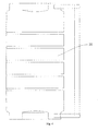
Fig. 1 is a sectional view of a pretreating filter according to an embodiment of the present disclosure; -
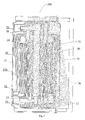
Fig. 2 is a sectional view of an integrated composite filter according to an embodiment of the present disclosure; -
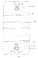
Fig. 3 is a front view of an integrated composite filter according to an embodiment of the present disclosure; -
Fig. 4 is a side view of an integrated composite filter according to an embodiment of the present disclosure; -
Fig. 5 is a top view of an integrated composite filter according to an embodiment of the present disclosure; -
Fig. 6 is a schematic view of an integrated composite filter according to an embodiment of the present disclosure showing a water inflow process; -
Fig. 7 is a schematic view of an integrated composite filter according to an embodiment of the present disclosure showing a pure water outflow process; -
Fig. 8 is a schematic view of an integrated composite filter according to an embodiment of the present disclosure showing a waste water outflow process; -
Fig. 9 is a water path diagram of a water purification apparatus according to an embodiment of the present disclosure. - Reference will be made in detail to embodiments of the present disclosure. The embodiments described herein with reference to drawings are explanatory, illustrative, and used to generally understand the present disclosure. The embodiments shall not be construed to limit the present disclosure. The same or similar elements and the elements having same or similar functions are denoted by like reference numerals throughout the descriptions.
- In the specification, it is to be understood that terms such as "central," "longitudinal," "lateral," "length," "width," "thickness," "upper," "lower," "vertical," "horizontal," "top," "bottom," "inner," "outer," should be construed to refer to the orientation as then described or as shown in the drawings under discussion. These relative terms are for convenience of description and do not require that the present invention be constructed or operated in a particular orientation.
- In addition, terms such as "first" and "second" are used herein for purposes of description and are not intended to indicate or imply relative importance or significance or to imply the number of indicated technical features. Thus, the feature defined with "first" and "second" may include one or more of this feature. In the description of the present invention, "a plurality of" means two or more than two, unless specified otherwise.
- In the description of the present disclosure, it should be understood that, unless specified or limited otherwise, the terms "mounted," "connected," "coupled," and the like are used broadly, and may be, for example, fixed connections, detachable connections, or integral connections; may also be mechanical or electrical connections; may also be direct connections or indirect connections via intervening structures; may also be inner communications of two elements, which can be understood by those skilled in the art according to specific situations.
- As shown in
Fig. 2 , an integratedcomposite filter 200 according to embodiments of the present disclosure includes: ashell 20, apretreating filtering element 100 and afiltering membrane 40. Theshell 20 defines achamber 21 therein, and defines araw water inlet 22, a pretreatedwater outlet 23, a pretreatedwater inlet 24, apure water outlet 25 and awaste water outlet 26 which are in communication with thechamber 21 respectively. Thepretreating filtering element 100 and the filteringmembrane 40 are both disposed within thechamber 21, and sequentially positioned between theraw water inlet 22 and thepure water outlet 25 as well as thewaste water outlet 26. The pretreatingfiltering element 100 is positioned between theraw water inlet 22 and the pretreatedwater outlet 23, and the filteringmembrane 40 is positioned between the pretreatedwater inlet 24 and thepure water outlet 25 as well as thewaste water outlet 26. - That is, from the view of an water flow direction, during a process of using the integrated
composite filter 200, water sequentially passes through theraw water inlet 22, thepretreating filtering element 100 and thefiltering membrane 40, then is divided into pure water and waste water at the filteringmembrane 40, and flows out from thepure water outlet 25 and thewaste water outlet 26, respectively. - Therefore, with the integrated
composite filter 200 according to embodiments of the present disclosure, thepretreating filtering element 100 is disposed between theraw water inlet 22 and the pretreatedwater outlet 23, and thefiltering membrane 40 is disposed between the pretreatedwater inlet 24 and thepure water outlet 25, thewaste water outlet 26. The water filtered by thepretreating filtering element 100 can be exhausted from the pretreatedwater outlet 23, then passes through the pretreatedwater inlet 24 to be further filtered after passing through a booster device, each component of the integratedcomposite filter 200 is disposed in the integratedcomposite filter 200, thus making the integratedcomposite filter 200 more compact in structure, and easy to assemble. - In some embodiments, the integrated
composite filter 200 further includes acentral tube 30, the pretreatingfiltering element 100 includes aninstallation tube 10 and a filtering assembly, theinstallation tube 10 is configured as a hollow cylinder, the filtering assembly is fitted over theinstallation tube 10, awater inlet channel 27 communicated with theraw water inlet 22 is defined between the filtering assembly and theshell 20, and a pretreatedwater outlet channel 23 communicated with the pretreatedwater outlet 23 is defined between the filtering assembly and theinstallation tube 10. - The
central tube 30 is mounted within theinstallation tube 10, is spaced apart from theinstallation tube 10 to define a filtering chamber communicated with the pretreatedwater inlet 24, and defines an end communicated with thepure water outlet 25 and awater inlet hole 31 in a sidewall of thecentral tube 30. Thefiltering membrane 40 is disposed within the filtering chamber and around an outer peripheral wall of thecentral tube 30, awaste water channel 29 communicated with thewaste water outlet 26 is defined between an outer peripheral wall of thefiltering membrane 40 and an inner peripheral wall of theinstallation tube 10. - First, the pretreating
filtering element 100 according to embodiments of the present disclosure will be described below in detail with reference to the drawings. - The pretreating
filtering element 100 according to embodiments of the present disclosure includes aninstallation tube 10 and a plurality of filtering layers, theinstallation tube 10 is configured as a hollow cylinder extended in an up-down direction, the plurality of filtering layers are sequentially fitted over theinstallation tube 10 from outside to inside. The plurality of filtering layers may be two filtering layers, and may also be three filtering layers, i.e. two or three filtering layers may be sequentially fitted over theinstallation tube 10 from outside to inside in a radial direction of theinstallation tube 10. - Therefore, as the plurality of filtering layers are sequentially fitted over the
installation tube 10, the pretreatingfiltering element 100 according to embodiments of the present disclosure is simple in structure and easy to assembly, and the pretreatingfiltering element 100 is designed integrally, and can be replaced together all at once after the pretreatingfiltering element 100 expires, thus solving the problem of frequent replacement of different filters for consumers and reducing the cost. - When the plurality of filtering layers are two filtering layers, the plurality of filtering layers include a PP layer and an activated carbon layer from outside to inside, the PP layer is constituted by a PP cotton or a PP non-woven winding layer, the activated carbon layer is constituted by an activated carbon fiber winding layer or an activated carbon rod layer. The two filtering layers are simple in structure, convenient to wind, and easy to install and replace.
- The pretreating
filtering element 100 according to embodiments of the present disclosure will be described in detail in the following when the plurality of filtering layers are three filtering layers. - As shown in
Fig. 1 , the pretreatingfiltering element 100 according to embodiments of the present disclosure includes aninstallation tube 10, afirst filtering layer 11, asecond filtering layer 12 and athird filtering layer 13. - Specifically, the
installation tube 10 is configured as a hollow cylinder extended in an up-down direction, thefirst filtering layer 11, thesecond filtering layer 12 and thethird filtering layer 13 are cylindrical, and sequentially fitted over theinstallation tube 10 from outside to inside. Thefirst filtering layer 11 is constituted by a PP cotton, thesecond filtering layer 12 is constituted by an activated carbon fiber winding layer, thethird filtering layer 13 is constituted by one of a PP cotton, a microfiltration membrane or an ultrafiltration membrane. - In other words, the pretreating
filtering element 100 according to embodiments of the present disclosure mainly consists of theinstallation tube 10 and three filtering layers sequentially fitted over theinstallation tube 10, the three filtering layers are thefirst filtering layer 11, thesecond filtering layer 12 and thethird filtering layer 13 in turn from outside to inside in a radial direction of theinstallation tube 10. Thefirst filtering layer 11 is constituted by a PP cotton, thesecond filtering layer 12 is constituted by an activated carbon fiber winding layer, thethird filtering layer 13 is constituted by one of a PP cotton, a microfiltration membrane or an ultrafiltration membrane. - That is, the pretreating
filtering element 100 does not include an adsorption structure which may produce fine carbon powders, and does not need to be washed after initial installation since no fine carbon powders flow out. The plurality of filtering layers are integrally disposed on theinstallation tube 10 respectively, and have basically identical service life, and thus can be replaced together after the pretreatingfiltering element 100 expires. - Therefore, the pretreating
filtering element 100 according to embodiments of the present disclosure is configured as such a structure which consists of the first to third filtering layers without fine carbon powders. The pretreatingfiltering element 100 with such a simple structure does not need to be washed during initial installation since no fine carbon powders flow out. The pretreatingfiltering element 100 is designed integrally, and can be replaced together all at once after the pretreatingfiltering element 100 expires, thus solving the problem of frequent replacement of different filters for consumers and reducing the cost. - In some embodiments, the pretreating
filtering element 100 further includes: anupper end cover 14, alower end cover 15 and a supportingtube 16. Specifically, theupper end cover 14 is disposed at a periphery of an upper end of theinstallation tube 10, thelower end cover 15 is disposed at a periphery of a lower end of theinstallation tube 10, in which thefirst filtering layer 11, thesecond filtering layer 12 and thethird filtering layer 13 are disposed between theupper end cover 14 and thelower end cover 15. The supportingtube 16 is fitted over theinstallation tube 10 and positioned between theupper end cover 14 and thelower end cover 15, in which thefirst filtering layer 11, thesecond filtering layer 12 and thethird filtering layer 13 are disposed between an outer peripheral surface of theinstallation tube 10 and an inner peripheral surface of the supportingtube 16, the supportingtube 16 defines a plurality of throughholes 161 penetrated therethrough. - As shown in
Fig. 1 , the pretreatingfiltering element 100 includes theinstallation tube 10, the upper end of theinstallation tube 10 is provided with the upper end cover 14 extended in the radical direction of theinstallation tube 10, the lower end of theinstallation tube 10 is provided with thelower end cover 15 extended in the radical direction of theinstallation tube 10, thefirst filtering layer 11, thesecond filtering layer 12 and thethird filtering layer 13 are disposed between theupper end cover 14 and thelower end cover 15, the supportingtube 16 is disposed outside thethird filtering layer 13, and upper and lower ends of the supportingtube 16 are abutted against theupper end cover 14 and thelower end cover 15 respectively. Therefore, the pretreatingfiltering element 100 of such a structure can effectively ensure the overall structural stability on the basis of simple structure. - Further, in some embodiments, the pretreating
filtering element 100 further includes: aninner tube 17 fitted over theinstallation tube 10, an inner peripheral surface of theinner tube 17 is spaced apart from the outer peripheral surface of theinstallation tube 10, upper and lower ends of theinner tube 17 are abutted against theupper end cover 14 and thelower end cover 15 respectively, thethird filtering layer 13 is fitted over theinner tube 17, and theinner tube 17 defines a plurality ofwater passing holes 171 penetrated therethrough. - That is, the
first filtering layer 11, thesecond filtering layer 12 and thethird filtering layer 13 are not nested around theinstallation tube 10 directly, but nested around theinner tube 17. Theinner tube 17 is fitted over theinstallation tube 10 and spaced apart from theinstallation tube 10 to define a pretreatedwater outlet channel 28, and theinner tube 17 defines a plurality ofwater passing holes 171 communicated with pretreated water outlet channel. - Specifically, when the pretreating
filtering element 100 according to an embodiment of the present disclosure is used, the raw water enters the pretreatingfiltering element 100 via a plurality of throughholes 161 in the supportingtube 16, and then enters the pretreated water outlet channel via the plurality ofwater passing holes 171 in theinner tube 17 after passing through thefirst filtering layer 11, thesecond filtering layer 12 and thethird filtering layer 13 sequentially. Afterwards, the pretreated water pretreated by the pretreatingfiltering element 100 is exhausted from the pretreated water outlet channel, and may be further filtered. - In some embodiments, upper and lower end surfaces of the
first filtering layer 11, thesecond filtering layer 12 and thethird filtering layer 13 are abutted against theupper end cover 14 and thelower end cover 15 respectively, theinstallation tube 10 is integrally formed with theupper end cover 14, and theinner tube 17 is integrally formed with thelower end cover 15. Thus, the pretreatingfiltering element 100 has a plurality of advantages, such as more compact structure, molding convenience for each component, high stability, simplified assembly process, and reduced cost. - In some embodiments, the
first filtering layer 11, i.e. the PP cotton, may be constituted by a PP non-woven winding layer, and may also be constituted by a folding PP non-woven or a winding PP cotton. Thesecond filtering layer 12 is constituted by an activated carbon fiber winding layer, and may also be constituted by an activated carbon rod or may be made of a granular activated carbon, an acid activated carbon and other materials with adsorption function. Thethird filtering layer 13 may be constituted by a high precision microfiltration membrane or an ultrafiltration membrane. - Alternatively, in some embodiments, the
first filtering layer 11 is a PP non-woven winding layer, and thethird filtering layer 13 is a microfiltration membrane. In some specific embodiments, thefirst filtering layer 11 is constituted by a PP cotton with a thickness of 5 microns, and thethird filtering layer 13 is constituted by a PP cotton with a thickness of 1 micron. In other specific embodiments, thefirst filtering layer 11 may also be constituted by a winding PP cotton, and thethird filtering layer 13 is constituted by an ultrafiltration membrane. - Preferably, in some embodiments, an inner diameter of the
third filtering layer 13 ranges from 60 mm to 70 mm, the difference between the inner diameter of thethird filtering layer 13 and an outer diameter of thefirst filtering layer 11 ranges from 15 mm to 20 mm, and the height of thefirst filtering layer 11, thesecond filtering layer 12 and thethird filtering layer 13 ranges from 100 mm to 110 mm in the up-down direction. Further, the inner diameter of thethird filtering layer 13 is 65 mm, the difference between the inner diameter of thethird filtering layer 13 and the outer diameter of thefirst filtering layer 11 is 18 mm, and the height of thefirst filtering layer 11, thesecond filtering layer 12 and thethird filtering layer 13 is 106 mm in the up-down direction. - Therefore, the service life of the
first filtering layer 11, thesecond filtering layer 12 and thethird filtering layer 13 of the pretreatingfiltering element 100 with such a structure can be ensured to be as consistent as possible, and thefirst filtering layer 11, thesecond filtering layer 12 and thethird filtering layer 13 can be replaced together after the pretreatingfiltering element 100 expires, thus solving the trouble of frequent replacement of different filters for consumers, ensuring that all the filtering layers are fully utilized, and avoiding the waste of a certain filtering layer. - The integrated
composite filter 200 according to embodiments of the present disclosure will be described below in detail with reference to the drawings. - As shown in
Fig. 2 to Fig. 8 , the integratedcomposite filter 200 according to embodiments of the present disclosure includes ashell 20, a pretreatingfiltering element 100, acentral tube 30 and afiltering membrane 40. The pretreatingfiltering element 100 is a pretreatingfiltering element 100 according to above embodiments of the present disclosure. - Specifically, the
shell 20 defines achamber 21 therein and is formed with araw water inlet 22, apretreated water outlet 23, apretreated water inlet 24, apure water outlet 25 and awaste water outlet 26 which are in communication with thechamber 21 respectively. The pretreatingfiltering element 100 is mounted within thechamber 21 and extended in an axial direction of thechamber 21, and includes theinstallation tube 10, thefirst filtering layer 11, thesecond filtering layer 12 and thethird filtering layer 13 in above embodiments. Awater inlet channel 27 communicated with theraw water inlet 22 is defined between thefirst filtering layer 11 and theshell 20, and a pretreatedwater outlet channel 28 communicated with the pretreatedwater outlet 23 is defined between thethird filtering layer 13 and theinstallation tube 10. - The
central tube 30 is mounted within theinstallation tube 10 and extended in the axial direction of theinstallation tube 10, and spaced apart from theinstallation tube 10 to define a filtering chamber communicated with the pretreatedwater inlet 24, a first end of thecentral tube 30 is communicated with thepure water outlet 25, thecentral tube 30 defines a plurality of water inlet holes 31 in a sidewall thereof. Thefiltering membrane 40 is disposed within the filtering chamber and around an outer peripheral wall of thecentral tube 30. Awaste water channel 29 is defined between an outer peripheral wall of thefiltering membrane 40 and an inner peripheral wall of theinstallation tube 10, and is communicated with thewaste water outlet 26. - That is, the integrated
composite filter 200 according to embodiments of the present disclosure adopts the pretreatingfiltering element 100 which consists of the first to third filtering layers without fine carbon powders, the pretreatingfiltering element 100 can pretreat the raw water, the pretreated water can be filtered again by thefiltering membrane 40, such that the pretreatment is combined with post-treatment to ensure the water purification effect. - As the pretreating
filtering element 100 according to embodiments of the present disclosure has above technical effects, the integratedcomposite filter 200 according to embodiments of the present disclosure also has corresponding technical effects, i.e. the pretreatingfiltering element 100 has simple structure, and does not need to be washed during initial installation since no fine carbon powders flow out; the pretreatingfiltering element 100 is designed integrally, and can be replaced together all at once after the pretreatingfiltering element 100 expires, thus solving the problem of frequent replacement of different filters for consumers and reducing the cost. - In addition, the pretreating
filtering element 100 and thefiltering membrane 40 constitute the integratedcomposite filter 200, and the pretreatingfiltering element 100 and thefiltering membrane 40 may have basically identical service life and may also be replaced together, the pretreatingfiltering element 100 is connected with thefiltering membrane 40, thereby making the structure compact, with less potential leakage points between pretreatment and post-treatment components, thus ensuring the whole performance of the integratedcomposite filter 200. - In some embodiments, the pretreating
filtering element 100 further includes: anupper end cover 14, alower end cover 15 and a supportingtube 16. Specifically, theupper end cover 14 is disposed at a periphery of an upper end of theinstallation tube 10, thelower end cover 15 is disposed at a periphery of a lower end of theinstallation tube 10, in which thefirst filtering layer 11, thesecond filtering layer 12 and thethird filtering layer 13 are disposed between theupper end cover 14 and thelower end cover 15. The supportingtube 16 is fitted over theinstallation tube 10 and positioned between theupper end cover 14 and thelower end cover 15, in which thefirst filtering layer 11, thesecond filtering layer 12 and thethird filtering layer 13 are disposed between an outer peripheral surface of theinstallation tube 10 and an inner peripheral surface of the supportingtube 16, the supportingtube 16 defines a plurality of throughholes 161 penetrated therethrough. - In some specific embodiments of the present disclosure, the
filtering membrane 40 is wound around thecentral tube 30, an upper end of thecentral tube 30 defines thepure water outlet 25 and an upper pretreated water inlet hole communicated with an upper end of thefiltering membrane 40, a lower end of thecentral tube 30 defines a lower pretreated water inlet hole communicated with a lower end of thefiltering membrane 40, thecentral tube 30 defines awater inlet hole 31 communicated with thefiltering membrane 40 in a sidewall of thecentral tube 30, and a pure water outlet channel communicating thewater inlet hoe 31 with thepure water outlet 25. - Specifically, the pretreating
filtering element 100 is positioned between thepure water inlet 22 and the pretreatedwater outlet 23, thefiltering membrane 40 is positioned between thepretreated water inlet 24 and thepure water outlet 25 as well as thewaste water outlet 26. The upper pretreated water inlet hole and the lower pretreated water inlet hole are communicated with the pretreatedwater inlet 24 respectively. - The integrated
composite filter 200 according to embodiments of the present disclosure can replace the multi-stage filter of the water purification system in the related art by integrating the pretreatingfiltering element 100 with thefiltering membrane 40, such that not only can the tube connection be simplified, the installation and replacement is more convenient, but also the amount of the joints and thus the potential leakage points can be reduced. Moreover, the integratedcomposite filter 200 after integrating the pretreatingfiltering element 100 with thefiltering membrane 40 enables the pretreatingfiltering element 100 and thefiltering membrane 40 to have basically identical service life, thus eliminating the problem of frequent replacement of filters and dramatically decreasing the usage cost. - In addition, since the
central tube 30 is formed with the upper pretreated water inlet hole and the lower pretreated water inlet hole, the pretreated water after boosted can flow into thefiltering membrane 40 to be filtered from the upper end and the lower end of thecentral tube 30 at the same time, thereby the amount of water can be increased by increasing the water flow capacity, thus satisfying the requirement of drinking while filtering. Therefore, the integratedcomposite filter 200 according to embodiments of the present disclosure integrated with a plurality of water purification filter materials can simplify the tube connection, installation and replacement of the water purification system with less potential leakage points, can improve the user experience, decrease the usage cost, have large flow capacity, and satisfy the requirement of drinking while filtering. - The pretreating
filtering element 100 further includes theinner tube 17 which is fitted over theinstallation tube 10, and the inner peripheral surface of theinner tube 17 is spaced apart from the outer peripheral surface of theinstallation tube 10, the upper and lower ends of the inner tube 1 7 are abutted against theupper end cover 14 and thelower end cover 15 respectively, thethird filtering layer 13 is fitted over theinner tube 17 which defines the plurality ofwater passing holes 171 penetrated therethrough. - Specifically, the integrated
composite filter 200 according to embodiments of the present disclosure is mainly constituted by theshell 20, the pretreatingfiltering element 100, thecentral tube 30 and thefiltering membrane 40, in which the pretreatingfiltering element 100 is mounted within theshell 20, thewater inlet channel 27 is defined between the supportingtube 161 of the pretreatingfiltering element 100 and theshell 20, thewater inlet channel 27 is communicated with theraw water inlet 22, the raw water entering theshell 20 from theraw water inlet 22 enters thewater inlet channel 27 first. - The supporting
tube 16 of the pretreatingfiltering element 100 defines the plurality of throughholes 161, the raw water in thewater inlet channel 27 sequentially enters thefirst filtering layer 11, thesecond filtering layer 12 and thethird filtering layer 13 via the plurality of throughholes 161, the pretreated water pretreated by thefirst filtering layer 11, thesecond filtering layer 12 and thethird filtering layer 13 enters the pretreatedwater outlet channel 28 between theinner tube 17 and theinstallation tube 10 from the plurality ofwater passing holes 171 in theinner tube 17, the pretreatedwater outlet channel 28 is communicated with the pretreatedwater outlet 23, the pretreated water may flow out from the pretreated water outlet 23 (as indicated by arrows inFig. 6 ). - The pretreated water flowing out from the pretreated
water outlet 23 may be boosted by a booster device, and the boosted pretreated water then enters theshell 20 from the pretreatedwater inlet 24, and enters the filtering chamber between thecentral tube 30 and the installation tube 10 (as indicated by arrows inFig. 6 ). The pretreated water filtered by thefiltering membrane 40 is divided into pure water and waste water. The pure water enters thecentral tube 30 from the water inlet holes 31 in thecentral tube 30 and then flows out from the pure water outlet 25 (as indicated by arrows inFig. 7 ). The waste water flows out from thewaste water outlet 26 after passing through thewaste water channel 29 between the filteringmembrane 40 and theinstallation tube 10 to complete the discharge of the waste water (as indicated by arrows inFig. 8 ). - Therefore, the integrated
composite filter 200 according to embodiments of the present disclosure has reasonable structure. Since the pretreatingfiltering element 100 has no granular activated carbon, there are no fine carbon powders flowing out during initial installation, and thereby the whole integratedcomposite filter 200 does not need to be washed for a long time, thus simplifying the installation procedure. - In some embodiments, the pretreating
filtering element 100 and thefiltering membrane 40 are formed in a nested manner. The pretreatingfiltering element 100 may be disposed at an outside of thefiltering membrane 40, and may also be disposed at an inside of thefiltering membrane 40. In some embodiments of the present disclosure, the pretreatingfiltering element 100 is preferably disposed at the outside of thefiltering membrane 40, thus facilitating the fitting of the pretreatingfiltering element 100 with other structures. - Further, in some specific embodiments of the present disclosure, the pretreating
filtering element 100 and thefiltering membrane 40 are formed coaxially. Preferably, the pretreatingfiltering element 100 defines the filtering chamber therein, and can be detachably inserted into the filtering chamber. Therefore, an assembly of the pretreatingfiltering element 100 of such a structure, thefiltering membrane 40 and theshell 20 is more reasonable in structure and more convenient to perform. - In some embodiments, the
raw water inlet 22 is configured as a single hole, the pretreatedwater outlet 23 and the pretreatedwater inlet 24 are formed in a nested manner, and the pretreatedwater inlet 24 is nested within the pretreatedwater outlet 23. Further, thepure water outlet 25 and thewaste water outlet 26 are formed in a nested manner, and thepure water outlet 25 is nested within thewaste water outlet 26. - That is, in the
shell 20 of the integratedcomposite filter 200 according to embodiments of the present disclosure, except that theraw water inlet 22 is configured as a single hole, the pretreatedwater outlet 23 and the pretreatedwater inlet 24 are formed in a nested manner, and thepure water outlet 25 and thewaste water outlet 26 are formed in a nested manner, i.e. the pretreatedwater inlet 24 is nested within the pretreatedwater outlet 23, and thepure water outlet 25 is nested within thewaste water outlet 26. - Therefore, individual tubes of the integrated
composite filter 200 of such a structure are fitted with each other more conveniently, thus reducing the joints connected with an outside and leakage points. Moreover, the individual water paths of the integratedcomposite filter 200 are distributed more reasonably, thus enabling the overall structure of the integratedcomposite filter 200 to be more compact, which facilitates the miniaturization design of the integratedcomposite filter 200. - In some embodiments, the pretreated
water outlet 23 is formed in a lower portion of theshell 20 and below theraw water inlet 22, thepure water outlet 25 is formed at an upper portion of theshell 20, an upper end of thecentral tube 30 is open and communicated with thepure water outlet 25. - That is, the pretreated
water outlet 23 and the pretreatedwater inlet 24 formed in a nested manner are positioned near the lower portion of theshell 20, and thepure water outlet 25 and thewaste water outlet 26 formed in a nested manner are positioned near the upper portion of theshell 20, theraw water inlet 22 is formed above the pretreatedwater outlet 23 and the pretreatedwater inlet 24. - When the integrated
composite filter 200 of such a structure is used, the raw water enters theshell 20 from theraw water inlet 22 at the lower portion of theshell 20, and then flows out from the outer hole, i.e. the pretreatedwater outlet 23, of the nested composite holes at a lower portion of the integratedcomposite filter 200 after being filtered by thefirst filtering layer 11, thesecond filtering layer 12 and thethird filtering layer 13. Then, the pretreated water enters theshell 20 from the pretreatedwater inlet 24 after being pressurized. Afterwards, the pretreated water flows upwardly from a bottom of the integratedcomposite filter 200 and enters the filtering chamber, and is filtered by thefiltering membrane 40 to divide the pretreated water into pure water and waste water, and the pure water and the waste water are exhausted from thepure water outlet 25 and thewaste water outlet 26 respectively. - Therefore, the water path of the integrated
composite filter 200 of such a structure is designed more reasonably, which facilitates the flow and filtration of the raw water, thus improving the water purification efficiency of the integratedcomposite filter 200. - In some embodiments, the
filtering membrane 40 may be a reverse osmosis membrane, an ultrafiltration membrane or a nanofiltration membrane. Therefore, thefiltering membrane 40 not only is convenient to assemble, but can reasonably control the cost of the integratedcomposite filter 200 on the basis of guaranteeing the filtering effect. - As shown in
Fig. 9 , thewater purification system 300 according to embodiments of the present disclosure includes the integratedcomposite filter 200 according to above embodiments of the present disclosure. As the integratedcomposite filter 200 according to embodiments of the present disclosure has above technical effects, thewater purification system 300 according to embodiments of the present disclosure also has corresponding technical effects, i.e. thewater purification system 300 has a compact overall structure and less leakage points, and does not need to be washed during initial installation, and individual filtering layers of the integratedcomposite filter 200 have basically identical service life and can be replaced together all at once, such that thewater purification system 300 is easy for consumers to use. - In some embodiments, the
water purification system 30 further includes abooster pump 50, thebooster pump 50 defines a water inlet communicated with the pretreatedwater outlet 23 and a water outlet communicated with the pretreatedwater inlet 24. That is, thebooster pump 50 is disposed between thepretreated water outlet 23 and the pretreatedwater inlet 24, the pretreated water flowing out from the pretreatedwater outlet 23 can enter the pretreatedwater inlet 24 after being boosted by thebooster pump 50 to be further filtered, thus improving water purification effect. - In some specific embodiments of the present disclosure, the
pure water outlet 25 is communicated with awater suction pump 70, a water storage device is disposed between thewater suction pump 70 and thepure water outlet 25. Preferably, the water storage device is aflexible water bag 60. Further, a waste waterratio solenoid valve 80 is disposed at thewaste water outlet 26. - The pure water flowing out from the
pure water outlet 25 can enter theflexible water bag 60, a micro-switch or a reed of theflexible water bag 60 gives a signal to a control board of thewater purification system 300 after theflexible water bag 60 is full of the pure water, then the control board gives a signal to close thebooster pump 50 and a switch at theraw water inlet 22, thus making thewater purification system 300 stop working. - Other components and operations of the
water purification system 300 according to embodiments of the present disclosure are well known to those skilled in the art and will not be described in detail herein. - Reference throughout this specification to "an embodiment," "some embodiments," "one embodiment", "another example," "an example," "a specific example," or "some examples," means that a particular feature, structure, material, or characteristic described in connection with the embodiment or example is included in at least one embodiment or example of the present disclosure. Thus, the appearances of the phrases such as "in some embodiments," "in one embodiment", "in an embodiment", "in another example," "in an example," "in a specific example," or "in some examples," in various places throughout this specification are not necessarily referring to the same embodiment or example of the present disclosure. Furthermore, the particular features, structures, materials, or characteristics may be combined in any suitable manner in one or more embodiments or examples.
- Although explanatory embodiments have been shown and described, it would be appreciated by those skilled in the art that the above embodiments cannot be construed to limit the present disclosure, and changes, alternatives, and modifications can be made in the embodiments without departing from spirit, principles and scope of the present disclosure.
Claims (15)
- An integrated composite filter, comprising:a shell defining a chamber therein, and defining a raw water inlet, a pretreated water outlet, a pretreated water inlet, a pure water outlet and a waste water outlet which are in communication with the chamber respectively;a pretreating fltering element disposed within the chamber;a filtering membrane disposed within the chamber,wherein the pretreating filtering element and the filtering membrane are sequentially positioned between the raw water inlet and the pure water outlet as well as the waste water outlet, and the pretreating filtering element is positioned between the raw water inlet and the pretreated water outlet, and the filtering membrane is positioned between the pretreated water inlet and the pure water outlet as well as the waste water outlet.
- The integrated composite filter according to claim 1, further comprising a central tube, wherein the pretreating filtering element comprises an installation tube configured as a hollow cylinder and a filtering assembly fitted over the installation tube, a water inlet channel communicated with the raw water inlet is defined between the filtering assembly and the shell, and a pretreated water outlet channel communicated with the pretreated water outlet is defined between the filtering assembly and the installation tube;
wherein the central tube is mounted within the installation tube, is spaced apart from the installation tube to define a filtering chamber communicated with the pretreated water inlet, and defines an end communicated with the pure water outlet and a water inlet hole in a sidewall of the central tube;
wherein the filtering membrane is disposed within the filtering chamber and around an outer peripheral wall of the central tube, a waste water channel communicated with the waste water outlet is defined between an outer peripheral wall of the filtering membrane and an inner peripheral wall of the installation tube. - The integrated composite filter according to claim 2, wherein the pretreating filtering element comprises first to third filtering layers sequentially fitted over the installation tube from outside to inside, the first filtering layer is constituted by a PP cotton, the second filtering layer is constituted by an activated carbon fiber winding layer, the third filtering layer is constituted by one of a PP cotton, a microfiltration membrane and an ultrafiltration membrane, a water inlet channel communicated with the raw water inlet being defined between the first filtering layer and the shell, a pretreated water outlet channel communicated with the pretreated water outlet being defined between the third filtering layer and the installation tube.
- The integrated composite filter according to claim 2, wherein the pretreating filtering element further comprises:an upper end cover disposed around a periphery of an upper end of the installation tube;a lower end cover disposed around a periphery of a lower end of the installation tube, the filtering assembly being disposed between the upper end cover and the lower end cover;a supporting tube defining a plurality of through holes penetrated therethrough, and fitted over the installation tube and positioned between the upper end cover and the lower end cover, the filtering assembly being disposed between an outer peripheral surface of the installation tube and an inner peripheral surface of the supporting tube.
- The integrated composite filter according to claim 4, wherein the pretreating filtering element further comprises:an inner tube defining a plurality of water passing holes penetrated therethrough, and fitted over the installation tube, an inner peripheral surface of the inner tube being spaced apart from the outer peripheral surface of the installation tube, the filtering assembly being fitted over the inner tube.
- The integrated composite filter according to claim 1, wherein the pretreating filtering element and the filtering membrane are formed in a nested manner.
- The integrated composite filter according to claim 6, wherein the pretreating filtering element and the filtering membrane are formed coaxially.
- The integrated composite filter according to claim 6, wherein the pretreating filtering element defines the filtering chamber therein, and is detachably inserted into the filtering chamber.
- The integrated composite filter according to any of claims 1-8, wherein the raw water inlet is configured as a single hole, the pretreated water outlet and the pretreated water inlet are formed in a nested manner, and the pretreated water inlet is nested within the pretreated water outlet.
- The integrated composite filter according to any of claims 1-8, wherein the pure water outlet and the waste water outlet are formed in a nested manner, and the pure water outlet is nested within the waste water outlet.
- The integrated composite filter according to any of claims 2-8, wherein the pretreated water outlet is formed in a lower portion of the shell and below the raw water inlet, the pure water outlet is formed at an upper portion of the shell, and an upper end of the central tube is open and communicated with the pure water outlet.
- The integrated composite filter according to any of claims 2-8, wherein the first filtering layer is constituted by a non-woven winding layer, and the third filtering layer is constituted by a CRN microfiltration membrane; or
wherein the first filtering layer is constituted by a PP cotton with a thickness of 5 microns, and the third filtering layer is constituted by a PP cotton with a thickness of 1 micron; or
wherein the first filtering layer is constituted by a winding PP cotton, and the third filtering layer is constituted by an ultrafiltration membrane. - The integrated composite filter according to any of claims 1-12, wherein the filtering membrane is a reverse osmosis membrane, an ultrafiltration membrane or a nanofiltration membrane.
- A water purification system, comprising an integrated composite filter according to any of claims 1-13.
- The water purification system according to claim 14, further comprising a booster pump defining a water inlet communicated with the pretreated water outlet and a water outlet communicated with the pretreated water inlet,
specially, wherein the water purification system further comprises a water suction pump communicated with the pure water outlet, and a water storage device disposed between the water suction pump and the pure water outlet, specially the water storage device is a flexible water bag;
specially, wherein a waste water ratio solenoid valve is disposed at the waste water outlet.
Applications Claiming Priority (2)
| Application Number | Priority Date | Filing Date | Title |
|---|---|---|---|
| CN201410814047.1A CN104528976A (en) | 2014-12-19 | 2014-12-19 | Integral combined filter element and water purifying system with same |
| CN201420826203.1U CN204310893U (en) | 2014-12-19 | 2014-12-19 | One composite filter element and the water cleaning systems with it |
Publications (2)
| Publication Number | Publication Date |
|---|---|
| EP3034470A1 true EP3034470A1 (en) | 2016-06-22 |
| EP3034470B1 EP3034470B1 (en) | 2018-10-17 |
Family
ID=54478535
Family Applications (1)
| Application Number | Title | Priority Date | Filing Date |
|---|---|---|---|
| EP15002665.6A Not-in-force EP3034470B1 (en) | 2014-12-19 | 2015-09-14 | Integrated composite filter and water purification system having the same |
Country Status (4)
| Country | Link |
|---|---|
| US (1) | US10399019B2 (en) |
| EP (1) | EP3034470B1 (en) |
| BR (1) | BR102015024287A2 (en) |
| WO (1) | WO2016095401A1 (en) |
Cited By (7)
| Publication number | Priority date | Publication date | Assignee | Title |
|---|---|---|---|---|
| EP3257822A4 (en) * | 2015-02-09 | 2018-08-29 | Foshan Shunde Midea Water Dispenser MFG. Co., Ltd. | Integrated composite filter cartridge and water purifying system having same |
| CN109336224A (en) * | 2018-11-30 | 2019-02-15 | 佛山市云米电器科技有限公司 | Collect the filter core and water purifier of ultrafiltration and reverse osmosis integrated design |
| CN110404327A (en) * | 2018-04-27 | 2019-11-05 | 芜湖美的厨卫电器制造有限公司 | Composite filter element and purifier |
| EP3549653A4 (en) * | 2017-10-30 | 2020-01-22 | Foshan Shunde Midea Water Dispenser MFG. Co., Ltd | COMPOSITE FILTER ELEMENT ASSEMBLY AND WATER PURIFICATION SYSTEM |
| CN111825161A (en) * | 2019-04-15 | 2020-10-27 | 佛山市顺德区美的饮水机制造有限公司 | Water purifier |
| CN112811630A (en) * | 2020-12-31 | 2021-05-18 | 江西挺进环保科技有限公司 | Easy-to-dismount type village and town domestic sewage treatment equipment |
| CN113979570A (en) * | 2021-12-07 | 2022-01-28 | 佛山市芯耀环保科技有限公司 | Composite filter element and water purifier |
Families Citing this family (8)
| Publication number | Priority date | Publication date | Assignee | Title |
|---|---|---|---|---|
| EP3594183B1 (en) * | 2017-03-07 | 2021-06-23 | Foshan Shunde Midea Water Dispenser Mfg. Co., Ltd. | Water purification system |
| CN107899279B (en) * | 2017-03-13 | 2021-06-25 | 佛山市顺德区美的饮水机制造有限公司 | Filter Assemblies and Water Purification Systems |
| CN107902784A (en) * | 2017-12-11 | 2018-04-13 | 武汉斯隆电气有限公司 | Instant heating type water purifier and its waterway control system |
| CN211886283U (en) * | 2019-08-02 | 2020-11-10 | 珠海格力电器股份有限公司 | A central pipe for roll-up membrane, roll-up membrane module and water purification system |
| CN112125425A (en) * | 2020-10-14 | 2020-12-25 | 珠海格力电器股份有限公司 | Composite filter element and water purifier |
| EP4159689A1 (en) * | 2021-09-29 | 2023-04-05 | Enregis GmbH | Vertical filter and waste water purification installation with integrated vertical filter |
| CN114380407A (en) * | 2021-12-21 | 2022-04-22 | 广东栗子科技有限公司 | Filter element shell and composite filter element thereof |
| DE102022110697A1 (en) * | 2022-05-02 | 2023-11-02 | INVI WATER GmbH | Encapsulated multi-stage filter cartridge for drinking water supply device and associated drinking water supply device |
Citations (5)
| Publication number | Priority date | Publication date | Assignee | Title |
|---|---|---|---|---|
| DE3805361A1 (en) * | 1987-02-20 | 1988-09-01 | Sartorius Gmbh | Integral filter for fluids made of a plurality of filter elements stacked one inside the other having different retention capacities and housing therefor |
| US20030164333A1 (en) * | 2002-02-12 | 2003-09-04 | Nohren John E. | In-line hydration pack biological filter |
| US20040104161A1 (en) * | 2002-09-26 | 2004-06-03 | Yves Gaignet | Module for purifying a fluid, in particular water |
| CN202193666U (en) * | 2011-02-11 | 2012-04-18 | 陈明初 | Multifunctional reverse osmosis (RO) water purification machine |
| CN203904091U (en) * | 2014-05-27 | 2014-10-29 | 佛山市顺德区美的饮水机制造有限公司 | Compound reverse osmosis filter element and purifier adopting same |
Family Cites Families (24)
| Publication number | Priority date | Publication date | Assignee | Title |
|---|---|---|---|---|
| DE3818860A1 (en) * | 1988-06-03 | 1989-12-07 | Seitz Filter Werke | FILTER ELEMENT |
| US5078876A (en) * | 1990-01-17 | 1992-01-07 | Trysan Research, Inc. | Apparatus for multistage purification of water |
| US4992170A (en) * | 1990-04-03 | 1991-02-12 | Eastman Kodak Company | Reverse osmosis filter cartridge assembly |
| US5620597A (en) * | 1990-04-23 | 1997-04-15 | Andelman; Marc D. | Non-fouling flow-through capacitor |
| US5445729A (en) * | 1993-10-07 | 1995-08-29 | Premier Manufactured Systems, Inc. | Counter top reverse osmosis system |
| CN1120520A (en) * | 1994-07-08 | 1996-04-17 | 三星电子株式会社 | Filter device for water purifier |
| US6099735A (en) * | 1998-06-04 | 2000-08-08 | Kelada; Maher I. | Counter top reverse osmosis water purification system |
| US7481917B2 (en) | 2004-03-05 | 2009-01-27 | Hydranautics | Filtration devices with embedded radio frequency identification (RFID) tags |
| US7267769B2 (en) * | 2004-09-24 | 2007-09-11 | International Environmental Technologies, Llc | Water purification system utilizing a carbon block pre-filter |
| JP2007136384A (en) * | 2005-11-21 | 2007-06-07 | Family Service Eiko Co Ltd | Permeate production equipment |
| CN101468298A (en) | 2007-12-27 | 2009-07-01 | 金德勇 | Composite filtering type filtering bottle |
| EP2244813A4 (en) * | 2008-01-28 | 2013-01-23 | Everpure Llc | Reverse osmosis system |
| CN101643286A (en) * | 2008-08-07 | 2010-02-10 | 谭昌林 | Water purifier |
| CN101670204B (en) | 2009-09-30 | 2012-06-20 | 宜昌菲尔泰过滤器厂 | Integral type filter core with large liquid filtering flow |
| JP2014522294A (en) | 2011-04-13 | 2014-09-04 | ジーエフディー ファブリックス,インク. | Filter elements for fluid filtration systems |
| CN102557287B (en) * | 2012-02-29 | 2014-10-01 | 广东品翔环保科技有限公司 | A reverse osmosis negative ion direct drinking machine |
| CN202705130U (en) | 2012-07-06 | 2013-01-30 | 慈溪市润鑫电器有限公司 | Combined type filter element of water purifier |
| CN103071334B (en) | 2013-01-30 | 2014-10-01 | 浙江沁园水处理科技有限公司 | Composite filter element and adapter thereof |
| CN203451305U (en) | 2013-09-18 | 2014-02-26 | 王志勇 | Water purifier |
| CN203513385U (en) * | 2013-10-08 | 2014-04-02 | 深圳市诚德来实业有限公司 | Water purification device |
| CN103755051A (en) * | 2014-01-26 | 2014-04-30 | 饶桂华 | Convenient water-saving all-composite nano-filtration and reverse osmosis water purifier |
| CN203938534U (en) | 2014-05-22 | 2014-11-12 | 张跃胜 | Loopful border water-purifying machine with reverse osmosis membrane |
| CN104528976A (en) * | 2014-12-19 | 2015-04-22 | 佛山市顺德区美的饮水机制造有限公司 | Integral combined filter element and water purifying system with same |
| CN204310893U (en) | 2014-12-19 | 2015-05-06 | 佛山市顺德区美的饮水机制造有限公司 | One composite filter element and the water cleaning systems with it |
-
2015
- 2015-04-30 WO PCT/CN2015/078075 patent/WO2016095401A1/en not_active Ceased
- 2015-09-08 US US14/847,085 patent/US10399019B2/en not_active Expired - Fee Related
- 2015-09-14 EP EP15002665.6A patent/EP3034470B1/en not_active Not-in-force
- 2015-09-22 BR BR102015024287A patent/BR102015024287A2/en not_active Application Discontinuation
Patent Citations (5)
| Publication number | Priority date | Publication date | Assignee | Title |
|---|---|---|---|---|
| DE3805361A1 (en) * | 1987-02-20 | 1988-09-01 | Sartorius Gmbh | Integral filter for fluids made of a plurality of filter elements stacked one inside the other having different retention capacities and housing therefor |
| US20030164333A1 (en) * | 2002-02-12 | 2003-09-04 | Nohren John E. | In-line hydration pack biological filter |
| US20040104161A1 (en) * | 2002-09-26 | 2004-06-03 | Yves Gaignet | Module for purifying a fluid, in particular water |
| CN202193666U (en) * | 2011-02-11 | 2012-04-18 | 陈明初 | Multifunctional reverse osmosis (RO) water purification machine |
| CN203904091U (en) * | 2014-05-27 | 2014-10-29 | 佛山市顺德区美的饮水机制造有限公司 | Compound reverse osmosis filter element and purifier adopting same |
Cited By (10)
| Publication number | Priority date | Publication date | Assignee | Title |
|---|---|---|---|---|
| EP3257822A4 (en) * | 2015-02-09 | 2018-08-29 | Foshan Shunde Midea Water Dispenser MFG. Co., Ltd. | Integrated composite filter cartridge and water purifying system having same |
| US10399011B2 (en) | 2015-02-09 | 2019-09-03 | Foshan Shunde Midea Water Dispenser Mfg. Co., Ltd. | Integrated composite filter cartridge and water purifying system having same |
| EP3549653A4 (en) * | 2017-10-30 | 2020-01-22 | Foshan Shunde Midea Water Dispenser MFG. Co., Ltd | COMPOSITE FILTER ELEMENT ASSEMBLY AND WATER PURIFICATION SYSTEM |
| CN110404327A (en) * | 2018-04-27 | 2019-11-05 | 芜湖美的厨卫电器制造有限公司 | Composite filter element and purifier |
| CN110404327B (en) * | 2018-04-27 | 2023-09-01 | 芜湖美的厨卫电器制造有限公司 | Composite filter element and water purification equipment |
| CN109336224A (en) * | 2018-11-30 | 2019-02-15 | 佛山市云米电器科技有限公司 | Collect the filter core and water purifier of ultrafiltration and reverse osmosis integrated design |
| CN111825161A (en) * | 2019-04-15 | 2020-10-27 | 佛山市顺德区美的饮水机制造有限公司 | Water purifier |
| CN111825161B (en) * | 2019-04-15 | 2022-08-26 | 佛山市顺德区美的饮水机制造有限公司 | Water purifier |
| CN112811630A (en) * | 2020-12-31 | 2021-05-18 | 江西挺进环保科技有限公司 | Easy-to-dismount type village and town domestic sewage treatment equipment |
| CN113979570A (en) * | 2021-12-07 | 2022-01-28 | 佛山市芯耀环保科技有限公司 | Composite filter element and water purifier |
Also Published As
| Publication number | Publication date |
|---|---|
| EP3034470B1 (en) | 2018-10-17 |
| WO2016095401A1 (en) | 2016-06-23 |
| US10399019B2 (en) | 2019-09-03 |
| US20160175746A1 (en) | 2016-06-23 |
| BR102015024287A2 (en) | 2016-07-12 |
Similar Documents
| Publication | Publication Date | Title |
|---|---|---|
| EP3034470B1 (en) | Integrated composite filter and water purification system having the same | |
| EP3257822B1 (en) | Water purifying system having an integrated composite filter cartridge | |
| CN104528976A (en) | Integral combined filter element and water purifying system with same | |
| CN104556457B (en) | Water cleaning systems | |
| WO2016095400A1 (en) | Composite filter cartridge and water purification system having same | |
| CN104524861A (en) | Pretreatment filter core and integrated composite filter core with same | |
| CN110975618A (en) | A roll film structure | |
| CN104671483A (en) | Water purifying device and control method thereof | |
| CN209307063U (en) | A combined filter element and water purifier | |
| CN105036400A (en) | Water purifier | |
| CN205367922U (en) | Water purifying system | |
| CN213112754U (en) | Two play water formula structures and have its filter core | |
| CN204779099U (en) | Water purifier | |
| CN104556449B (en) | Composite filter element and water purification system including same | |
| CN204310891U (en) | Water cleaning systems | |
| CN217757058U (en) | Filter element with adjustable water quality | |
| CN204310893U (en) | One composite filter element and the water cleaning systems with it | |
| WO2018161439A1 (en) | Composite filter element, composite filter element assembly, and water purification system | |
| EP3392200B1 (en) | Water purification system | |
| CN208603866U (en) | A kind of detachable reverse osmosis composite filter element component | |
| CN104556448B (en) | Water cleaning systems | |
| CN204529499U (en) | Purifier | |
| CN210065260U (en) | Internal pressure type roll type reverse osmosis element | |
| CN110255748B (en) | Composite filter element assembly and water purification system | |
| CN204522484U (en) | Preprocessing filter element and the one composite filter element with it |
Legal Events
| Date | Code | Title | Description |
|---|---|---|---|
| PUAI | Public reference made under article 153(3) epc to a published international application that has entered the european phase |
Free format text: ORIGINAL CODE: 0009012 |
|
| AK | Designated contracting states |
Kind code of ref document: A1 Designated state(s): AL AT BE BG CH CY CZ DE DK EE ES FI FR GB GR HR HU IE IS IT LI LT LU LV MC MK MT NL NO PL PT RO RS SE SI SK SM TR |
|
| AX | Request for extension of the european patent |
Extension state: BA ME |
|
| STAA | Information on the status of an ep patent application or granted ep patent |
Free format text: STATUS: REQUEST FOR EXAMINATION WAS MADE |
|
| 17P | Request for examination filed |
Effective date: 20161221 |
|
| RBV | Designated contracting states (corrected) |
Designated state(s): AL AT BE BG CH CY CZ DE DK EE ES FI FR GB GR HR HU IE IS IT LI LT LU LV MC MK MT NL NO PL PT RO RS SE SI SK SM TR |
|
| GRAP | Despatch of communication of intention to grant a patent |
Free format text: ORIGINAL CODE: EPIDOSNIGR1 |
|
| STAA | Information on the status of an ep patent application or granted ep patent |
Free format text: STATUS: GRANT OF PATENT IS INTENDED |
|
| RIC1 | Information provided on ipc code assigned before grant |
Ipc: B01D 39/16 20060101ALI20180216BHEP Ipc: B01D 63/06 20060101ALI20180216BHEP Ipc: B01D 69/10 20060101ALI20180216BHEP Ipc: C02F 1/00 20060101AFI20180216BHEP Ipc: C02F 1/44 20060101ALI20180216BHEP Ipc: C02F 1/28 20060101ALI20180216BHEP Ipc: B01D 61/28 20060101ALI20180216BHEP Ipc: B01D 61/18 20060101ALI20180216BHEP |
|
| INTG | Intention to grant announced |
Effective date: 20180315 |
|
| GRAJ | Information related to disapproval of communication of intention to grant by the applicant or resumption of examination proceedings by the epo deleted |
Free format text: ORIGINAL CODE: EPIDOSDIGR1 |
|
| STAA | Information on the status of an ep patent application or granted ep patent |
Free format text: STATUS: REQUEST FOR EXAMINATION WAS MADE |
|
| GRAR | Information related to intention to grant a patent recorded |
Free format text: ORIGINAL CODE: EPIDOSNIGR71 |
|
| GRAS | Grant fee paid |
Free format text: ORIGINAL CODE: EPIDOSNIGR3 |
|
| INTC | Intention to grant announced (deleted) | ||
| STAA | Information on the status of an ep patent application or granted ep patent |
Free format text: STATUS: GRANT OF PATENT IS INTENDED |
|
| RAP1 | Party data changed (applicant data changed or rights of an application transferred) |
Owner name: GUANGDONG MIDEA WATER DISPENSER MFG. CO., LTD Owner name: MIDEA GROUP CO., LTD. |
|
| GRAA | (expected) grant |
Free format text: ORIGINAL CODE: 0009210 |
|
| STAA | Information on the status of an ep patent application or granted ep patent |
Free format text: STATUS: THE PATENT HAS BEEN GRANTED |
|
| INTG | Intention to grant announced |
Effective date: 20180905 |
|
| AK | Designated contracting states |
Kind code of ref document: B1 Designated state(s): AL AT BE BG CH CY CZ DE DK EE ES FI FR GB GR HR HU IE IS IT LI LT LU LV MC MK MT NL NO PL PT RO RS SE SI SK SM TR |
|
| REG | Reference to a national code |
Ref country code: GB Ref legal event code: FG4D |
|
| REG | Reference to a national code |
Ref country code: CH Ref legal event code: EP |
|
| REG | Reference to a national code |
Ref country code: IE Ref legal event code: FG4D |
|
| REG | Reference to a national code |
Ref country code: DE Ref legal event code: R096 Ref document number: 602015018120 Country of ref document: DE Ref country code: AT Ref legal event code: REF Ref document number: 1053791 Country of ref document: AT Kind code of ref document: T Effective date: 20181115 |
|
| REG | Reference to a national code |
Ref country code: NL Ref legal event code: MP Effective date: 20181017 |
|
| REG | Reference to a national code |
Ref country code: LT Ref legal event code: MG4D |
|
| REG | Reference to a national code |
Ref country code: AT Ref legal event code: MK05 Ref document number: 1053791 Country of ref document: AT Kind code of ref document: T Effective date: 20181017 |
|
| PG25 | Lapsed in a contracting state [announced via postgrant information from national office to epo] |
Ref country code: NL Free format text: LAPSE BECAUSE OF FAILURE TO SUBMIT A TRANSLATION OF THE DESCRIPTION OR TO PAY THE FEE WITHIN THE PRESCRIBED TIME-LIMIT Effective date: 20181017 |
|
| PG25 | Lapsed in a contracting state [announced via postgrant information from national office to epo] |
Ref country code: IS Free format text: LAPSE BECAUSE OF FAILURE TO SUBMIT A TRANSLATION OF THE DESCRIPTION OR TO PAY THE FEE WITHIN THE PRESCRIBED TIME-LIMIT Effective date: 20190217 Ref country code: FI Free format text: LAPSE BECAUSE OF FAILURE TO SUBMIT A TRANSLATION OF THE DESCRIPTION OR TO PAY THE FEE WITHIN THE PRESCRIBED TIME-LIMIT Effective date: 20181017 Ref country code: AT Free format text: LAPSE BECAUSE OF FAILURE TO SUBMIT A TRANSLATION OF THE DESCRIPTION OR TO PAY THE FEE WITHIN THE PRESCRIBED TIME-LIMIT Effective date: 20181017 Ref country code: PL Free format text: LAPSE BECAUSE OF FAILURE TO SUBMIT A TRANSLATION OF THE DESCRIPTION OR TO PAY THE FEE WITHIN THE PRESCRIBED TIME-LIMIT Effective date: 20181017 Ref country code: LT Free format text: LAPSE BECAUSE OF FAILURE TO SUBMIT A TRANSLATION OF THE DESCRIPTION OR TO PAY THE FEE WITHIN THE PRESCRIBED TIME-LIMIT Effective date: 20181017 Ref country code: NO Free format text: LAPSE BECAUSE OF FAILURE TO SUBMIT A TRANSLATION OF THE DESCRIPTION OR TO PAY THE FEE WITHIN THE PRESCRIBED TIME-LIMIT Effective date: 20190117 Ref country code: LV Free format text: LAPSE BECAUSE OF FAILURE TO SUBMIT A TRANSLATION OF THE DESCRIPTION OR TO PAY THE FEE WITHIN THE PRESCRIBED TIME-LIMIT Effective date: 20181017 Ref country code: ES Free format text: LAPSE BECAUSE OF FAILURE TO SUBMIT A TRANSLATION OF THE DESCRIPTION OR TO PAY THE FEE WITHIN THE PRESCRIBED TIME-LIMIT Effective date: 20181017 Ref country code: BG Free format text: LAPSE BECAUSE OF FAILURE TO SUBMIT A TRANSLATION OF THE DESCRIPTION OR TO PAY THE FEE WITHIN THE PRESCRIBED TIME-LIMIT Effective date: 20190117 Ref country code: HR Free format text: LAPSE BECAUSE OF FAILURE TO SUBMIT A TRANSLATION OF THE DESCRIPTION OR TO PAY THE FEE WITHIN THE PRESCRIBED TIME-LIMIT Effective date: 20181017 |
|
| PG25 | Lapsed in a contracting state [announced via postgrant information from national office to epo] |
Ref country code: AL Free format text: LAPSE BECAUSE OF FAILURE TO SUBMIT A TRANSLATION OF THE DESCRIPTION OR TO PAY THE FEE WITHIN THE PRESCRIBED TIME-LIMIT Effective date: 20181017 Ref country code: SE Free format text: LAPSE BECAUSE OF FAILURE TO SUBMIT A TRANSLATION OF THE DESCRIPTION OR TO PAY THE FEE WITHIN THE PRESCRIBED TIME-LIMIT Effective date: 20181017 Ref country code: PT Free format text: LAPSE BECAUSE OF FAILURE TO SUBMIT A TRANSLATION OF THE DESCRIPTION OR TO PAY THE FEE WITHIN THE PRESCRIBED TIME-LIMIT Effective date: 20190217 Ref country code: RS Free format text: LAPSE BECAUSE OF FAILURE TO SUBMIT A TRANSLATION OF THE DESCRIPTION OR TO PAY THE FEE WITHIN THE PRESCRIBED TIME-LIMIT Effective date: 20181017 Ref country code: GR Free format text: LAPSE BECAUSE OF FAILURE TO SUBMIT A TRANSLATION OF THE DESCRIPTION OR TO PAY THE FEE WITHIN THE PRESCRIBED TIME-LIMIT Effective date: 20190118 |
|
| REG | Reference to a national code |
Ref country code: DE Ref legal event code: R097 Ref document number: 602015018120 Country of ref document: DE |
|
| PG25 | Lapsed in a contracting state [announced via postgrant information from national office to epo] |
Ref country code: CZ Free format text: LAPSE BECAUSE OF FAILURE TO SUBMIT A TRANSLATION OF THE DESCRIPTION OR TO PAY THE FEE WITHIN THE PRESCRIBED TIME-LIMIT Effective date: 20181017 Ref country code: DK Free format text: LAPSE BECAUSE OF FAILURE TO SUBMIT A TRANSLATION OF THE DESCRIPTION OR TO PAY THE FEE WITHIN THE PRESCRIBED TIME-LIMIT Effective date: 20181017 Ref country code: IT Free format text: LAPSE BECAUSE OF FAILURE TO SUBMIT A TRANSLATION OF THE DESCRIPTION OR TO PAY THE FEE WITHIN THE PRESCRIBED TIME-LIMIT Effective date: 20181017 |
|
| PLBE | No opposition filed within time limit |
Free format text: ORIGINAL CODE: 0009261 |
|
| STAA | Information on the status of an ep patent application or granted ep patent |
Free format text: STATUS: NO OPPOSITION FILED WITHIN TIME LIMIT |
|
| PG25 | Lapsed in a contracting state [announced via postgrant information from national office to epo] |
Ref country code: SM Free format text: LAPSE BECAUSE OF FAILURE TO SUBMIT A TRANSLATION OF THE DESCRIPTION OR TO PAY THE FEE WITHIN THE PRESCRIBED TIME-LIMIT Effective date: 20181017 Ref country code: RO Free format text: LAPSE BECAUSE OF FAILURE TO SUBMIT A TRANSLATION OF THE DESCRIPTION OR TO PAY THE FEE WITHIN THE PRESCRIBED TIME-LIMIT Effective date: 20181017 Ref country code: EE Free format text: LAPSE BECAUSE OF FAILURE TO SUBMIT A TRANSLATION OF THE DESCRIPTION OR TO PAY THE FEE WITHIN THE PRESCRIBED TIME-LIMIT Effective date: 20181017 Ref country code: SK Free format text: LAPSE BECAUSE OF FAILURE TO SUBMIT A TRANSLATION OF THE DESCRIPTION OR TO PAY THE FEE WITHIN THE PRESCRIBED TIME-LIMIT Effective date: 20181017 |
|
| 26N | No opposition filed |
Effective date: 20190718 |
|
| PG25 | Lapsed in a contracting state [announced via postgrant information from national office to epo] |
Ref country code: SI Free format text: LAPSE BECAUSE OF FAILURE TO SUBMIT A TRANSLATION OF THE DESCRIPTION OR TO PAY THE FEE WITHIN THE PRESCRIBED TIME-LIMIT Effective date: 20181017 |
|
| PGFP | Annual fee paid to national office [announced via postgrant information from national office to epo] |
Ref country code: FR Payment date: 20190930 Year of fee payment: 5 Ref country code: DE Payment date: 20190913 Year of fee payment: 5 |
|
| PGFP | Annual fee paid to national office [announced via postgrant information from national office to epo] |
Ref country code: GB Payment date: 20190919 Year of fee payment: 5 |
|
| PG25 | Lapsed in a contracting state [announced via postgrant information from national office to epo] |
Ref country code: TR Free format text: LAPSE BECAUSE OF FAILURE TO SUBMIT A TRANSLATION OF THE DESCRIPTION OR TO PAY THE FEE WITHIN THE PRESCRIBED TIME-LIMIT Effective date: 20181017 |
|
| PG25 | Lapsed in a contracting state [announced via postgrant information from national office to epo] |
Ref country code: MC Free format text: LAPSE BECAUSE OF FAILURE TO SUBMIT A TRANSLATION OF THE DESCRIPTION OR TO PAY THE FEE WITHIN THE PRESCRIBED TIME-LIMIT Effective date: 20181017 |
|
| REG | Reference to a national code |
Ref country code: CH Ref legal event code: PL |
|
| PG25 | Lapsed in a contracting state [announced via postgrant information from national office to epo] |
Ref country code: CH Free format text: LAPSE BECAUSE OF NON-PAYMENT OF DUE FEES Effective date: 20190930 Ref country code: LU Free format text: LAPSE BECAUSE OF NON-PAYMENT OF DUE FEES Effective date: 20190914 Ref country code: LI Free format text: LAPSE BECAUSE OF NON-PAYMENT OF DUE FEES Effective date: 20190930 Ref country code: IE Free format text: LAPSE BECAUSE OF NON-PAYMENT OF DUE FEES Effective date: 20190914 |
|
| REG | Reference to a national code |
Ref country code: BE Ref legal event code: MM Effective date: 20190930 |
|
| PG25 | Lapsed in a contracting state [announced via postgrant information from national office to epo] |
Ref country code: BE Free format text: LAPSE BECAUSE OF NON-PAYMENT OF DUE FEES Effective date: 20190930 |
|
| REG | Reference to a national code |
Ref country code: DE Ref legal event code: R119 Ref document number: 602015018120 Country of ref document: DE |
|
| GBPC | Gb: european patent ceased through non-payment of renewal fee |
Effective date: 20200914 |
|
| PG25 | Lapsed in a contracting state [announced via postgrant information from national office to epo] |
Ref country code: CY Free format text: LAPSE BECAUSE OF FAILURE TO SUBMIT A TRANSLATION OF THE DESCRIPTION OR TO PAY THE FEE WITHIN THE PRESCRIBED TIME-LIMIT Effective date: 20181017 |
|
| PG25 | Lapsed in a contracting state [announced via postgrant information from national office to epo] |
Ref country code: FR Free format text: LAPSE BECAUSE OF NON-PAYMENT OF DUE FEES Effective date: 20200930 Ref country code: DE Free format text: LAPSE BECAUSE OF NON-PAYMENT OF DUE FEES Effective date: 20210401 Ref country code: HU Free format text: LAPSE BECAUSE OF FAILURE TO SUBMIT A TRANSLATION OF THE DESCRIPTION OR TO PAY THE FEE WITHIN THE PRESCRIBED TIME-LIMIT; INVALID AB INITIO Effective date: 20150914 Ref country code: MT Free format text: LAPSE BECAUSE OF FAILURE TO SUBMIT A TRANSLATION OF THE DESCRIPTION OR TO PAY THE FEE WITHIN THE PRESCRIBED TIME-LIMIT Effective date: 20181017 |
|
| PG25 | Lapsed in a contracting state [announced via postgrant information from national office to epo] |
Ref country code: GB Free format text: LAPSE BECAUSE OF NON-PAYMENT OF DUE FEES Effective date: 20200914 |
|
| PG25 | Lapsed in a contracting state [announced via postgrant information from national office to epo] |
Ref country code: MK Free format text: LAPSE BECAUSE OF FAILURE TO SUBMIT A TRANSLATION OF THE DESCRIPTION OR TO PAY THE FEE WITHIN THE PRESCRIBED TIME-LIMIT Effective date: 20181017 |