EP3034408A1 - Compartment based inlet particle separator system - Google Patents
Compartment based inlet particle separator system Download PDFInfo
- Publication number
- EP3034408A1 EP3034408A1 EP15199431.6A EP15199431A EP3034408A1 EP 3034408 A1 EP3034408 A1 EP 3034408A1 EP 15199431 A EP15199431 A EP 15199431A EP 3034408 A1 EP3034408 A1 EP 3034408A1
- Authority
- EP
- European Patent Office
- Prior art keywords
- diffuser
- compartment
- air inlet
- apu
- inlet
- Prior art date
- Legal status (The legal status is an assumption and is not a legal conclusion. Google has not performed a legal analysis and makes no representation as to the accuracy of the status listed.)
- Granted
Links
Images



Classifications
-
- F—MECHANICAL ENGINEERING; LIGHTING; HEATING; WEAPONS; BLASTING
- F01—MACHINES OR ENGINES IN GENERAL; ENGINE PLANTS IN GENERAL; STEAM ENGINES
- F01D—NON-POSITIVE DISPLACEMENT MACHINES OR ENGINES, e.g. STEAM TURBINES
- F01D1/00—Non-positive-displacement machines or engines, e.g. steam turbines
- F01D1/18—Non-positive-displacement machines or engines, e.g. steam turbines without stationary working-fluid guiding means
- F01D1/20—Non-positive-displacement machines or engines, e.g. steam turbines without stationary working-fluid guiding means traversed by the working-fluid substantially axially
-
- B—PERFORMING OPERATIONS; TRANSPORTING
- B64—AIRCRAFT; AVIATION; COSMONAUTICS
- B64D—EQUIPMENT FOR FITTING IN OR TO AIRCRAFT; FLIGHT SUITS; PARACHUTES; ARRANGEMENT OR MOUNTING OF POWER PLANTS OR PROPULSION TRANSMISSIONS IN AIRCRAFT
- B64D33/00—Arrangement in aircraft of power plant parts or auxiliaries not otherwise provided for
- B64D33/02—Arrangement in aircraft of power plant parts or auxiliaries not otherwise provided for of combustion air intakes
-
- B—PERFORMING OPERATIONS; TRANSPORTING
- B64—AIRCRAFT; AVIATION; COSMONAUTICS
- B64D—EQUIPMENT FOR FITTING IN OR TO AIRCRAFT; FLIGHT SUITS; PARACHUTES; ARRANGEMENT OR MOUNTING OF POWER PLANTS OR PROPULSION TRANSMISSIONS IN AIRCRAFT
- B64D33/00—Arrangement in aircraft of power plant parts or auxiliaries not otherwise provided for
-
- B—PERFORMING OPERATIONS; TRANSPORTING
- B64—AIRCRAFT; AVIATION; COSMONAUTICS
- B64D—EQUIPMENT FOR FITTING IN OR TO AIRCRAFT; FLIGHT SUITS; PARACHUTES; ARRANGEMENT OR MOUNTING OF POWER PLANTS OR PROPULSION TRANSMISSIONS IN AIRCRAFT
- B64D41/00—Power installations for auxiliary purposes
-
- B—PERFORMING OPERATIONS; TRANSPORTING
- B64—AIRCRAFT; AVIATION; COSMONAUTICS
- B64D—EQUIPMENT FOR FITTING IN OR TO AIRCRAFT; FLIGHT SUITS; PARACHUTES; ARRANGEMENT OR MOUNTING OF POWER PLANTS OR PROPULSION TRANSMISSIONS IN AIRCRAFT
- B64D33/00—Arrangement in aircraft of power plant parts or auxiliaries not otherwise provided for
- B64D33/02—Arrangement in aircraft of power plant parts or auxiliaries not otherwise provided for of combustion air intakes
- B64D2033/0213—Arrangement in aircraft of power plant parts or auxiliaries not otherwise provided for of combustion air intakes specially adapted for auxiliary power units (APU's)
-
- B—PERFORMING OPERATIONS; TRANSPORTING
- B64—AIRCRAFT; AVIATION; COSMONAUTICS
- B64D—EQUIPMENT FOR FITTING IN OR TO AIRCRAFT; FLIGHT SUITS; PARACHUTES; ARRANGEMENT OR MOUNTING OF POWER PLANTS OR PROPULSION TRANSMISSIONS IN AIRCRAFT
- B64D33/00—Arrangement in aircraft of power plant parts or auxiliaries not otherwise provided for
- B64D33/02—Arrangement in aircraft of power plant parts or auxiliaries not otherwise provided for of combustion air intakes
- B64D2033/0246—Arrangement in aircraft of power plant parts or auxiliaries not otherwise provided for of combustion air intakes comprising particle separators
-
- B—PERFORMING OPERATIONS; TRANSPORTING
- B64—AIRCRAFT; AVIATION; COSMONAUTICS
- B64D—EQUIPMENT FOR FITTING IN OR TO AIRCRAFT; FLIGHT SUITS; PARACHUTES; ARRANGEMENT OR MOUNTING OF POWER PLANTS OR PROPULSION TRANSMISSIONS IN AIRCRAFT
- B64D41/00—Power installations for auxiliary purposes
- B64D2041/002—Mounting arrangements for auxiliary power units (APU's)
Definitions
- the present invention generally relates to inlet particle separator systems for auxiliary power units (APUs), and more particularly relates to compartment based inlet particle separator systems for aircraft that include an APU system compartment.
- APUs auxiliary power units
- the main propulsion engines not only provide propulsion for the aircraft, but may also be used to drive various other rotating components such as, for example, generators, compressors, and pumps, to thereby supply electrical and/or pneumatic power.
- the main propulsion engines may not be capable of supplying the power needed for propulsion as well as the power to drive these other rotating components.
- many aircraft include an auxiliary power unit (APU) to supplement the main propulsion engines in providing electrical and/or pneumatic power.
- An APU may also be used to start the propulsion engines.
- APU-equipped aircraft are operated in environments that have a high concentration of fine dust particles (e.g., ⁇ 30 ⁇ m) suspended in the air.
- fine dust particles e.g., ⁇ 30 ⁇ m
- the fine dust particles can plug the holes in effusion cooled combustors, and can plug and corrode the high temperature turbine passages and hardware.
- IPS inlet particle separator system
- IPSs are designed to separate out relatively large particles (e.g., 100 ⁇ m ⁇ 1000 ⁇ m) but are less efficient at separating out fine particles. This is because these systems typically rely on particle inertia to move the particles into a separate collector and scavenge system. Fine particles, with relatively lower inertia, are much more inclined to follow the inlet airflow into the gas turbine engine, resulting in low separation efficiencies. Thus, many aircraft additionally include one or more systems to remove these fine particles. These additional systems include barrier filters (self-cleaning and non-self-cleaning), vortex panels, and multi-channel particle separator (MCPS) systems.
- barrier filters self-cleaning and non-self-cleaning
- vortex panels e.g., vortex panels
- MCPS multi-channel particle separator
- a compartment based inlet particle separator system for an aircraft that includes an auxiliary power unit (APU) system compartment, includes a separation barrier wall, a ram air inlet opening, a diffuser, and an inlet particle separator (IPS).
- the separation barrier wall is disposed within the APU system compartment and is configured to divide the APU system compartment into an air inlet compartment and an APU compartment.
- the separation barrier wall has an APU air inlet port formed therein that provides fluid communication between the air inlet compartment and the APU compartment.
- the ram air inlet opening is formed in the air inlet compartment for receiving a flow of ram air.
- the diffuser is disposed within the air inlet compartment and has a diffuser inlet and a diffuser outlet.
- the diffuser inlet is coupled to receive ram air from the ram air inlet opening.
- the diffuser outlet is in fluid communication with, and is configured to discharge ram air into, the air inlet compartment.
- the IPS is disposed within the air inlet compartment between the diffuser outlet and the APU air inlet port.
- an auxiliary power unit (APU) air inlet system for an aircraft that includes an APU system compartment includes a separation barrier wall, a ram air inlet opening, a diffuser, a plurality of flow control surfaces, and an inlet particle separator (IPS).
- the separation barrier wall is disposed within the APU system compartment and is configured to divide the APU system compartment into an air inlet compartment and an APU compartment.
- the separation barrier wall has an APU air inlet port formed therein that provides fluid communication between the air inlet compartment and the APU compartment.
- the ram air inlet opening is formed in the air inlet compartment for receiving a flow of ram air.
- the diffuser is disposed within the air inlet compartment and has a diffuser inlet, a diffuser outlet, and a bypass port disposed between the diffuser inlet and the diffuser outlet.
- the diffuser inlet is coupled to receive ram air from the ram air inlet opening.
- the diffuser outlet is in fluid communication with, and is configured to discharge ram air into, the air inlet compartment.
- the bypass port is in fluid communication with the APU air inlet port.
- the flow control surfaces are rotationally mounted within the diffuser and are movable between a first position, in which the flow control surfaces direct ram air through the bypass port and into the APU air inlet port, and a second position, in which the flow control surfaces direct ram air through the diffuser outlet.
- the inlet particle separator is disposed within the air inlet compartment between the diffuser outlet and the APU air inlet port.
- an auxiliary power unit (APU) air inlet system for an aircraft that includes an APU system compartment includes a separation barrier wall, a ram air inlet opening, a transverse diffuser, an inlet particle separator (IPS), and an APU.
- the separation barrier wall is disposed within the APU system compartment and is configured to divide the APU system compartment into an air inlet compartment and an APU compartment.
- the separation barrier wall has an APU air inlet port formed therein that provides fluid communication between the air inlet compartment and the APU compartment.
- the ram air inlet opening is formed in the air inlet compartment for receiving a flow of ram air.
- the transverse diffuser is disposed within the air inlet compartment and has a diffuser inlet and a diffuser outlet.
- the diffuser inlet is coupled to receive ram air from the ram air inlet opening.
- the diffuser outlet is in fluid communication with, and is configured to discharge ram air into, the air inlet compartment.
- the IPS is disposed within the air inlet compartment between the diffuser outlet and the APU air inlet port.
- the APU is disposed within the APU compartment, and has an air inlet in fluid communication with the APU air inlet port.
- FIG. 1 a cross-sectional schematic of a tail cone portion of an aircraft 100 is depicted.
- the aircraft 100 includes an auxiliary power unit (APU) system compartment 102 that is defined by an exterior surface 104, a forward firewall 106, and an aft firewall 108.
- the forward firewall 106 separates the APU system compartment 102 from other sections of the aircraft 100.
- the APU system compartment 102 is formed in the tailcone section of the aircraft 100. It will be appreciated, however, that this is merely exemplary, and that the APU system compartment 102 could be formed in any one of numerous other sections of the aircraft 100. It will additionally be appreciated that, depending on its location in the aircraft 100, the APU system compartment 102 may be defined by only one forward firewall 106 or aft firewall 108.
- the APU system compartment 102 additionally includes a separation barrier wall 112.
- the separation barrier wall 112 extends between the forward firewall 106 and the aft firewall 108, and divides the APU system compartment 102 into two separate compartments - an air inlet compartment 114 and an APU compartment 116.
- the separation barrier wall 112 has an APU air inlet port 115 formed therein that provides fluid communication between the air inlet compartment 114 and an inlet to an APU 128.
- a ram air inlet opening 118 is formed in the air inlet compartment 114 and extends through the exterior surface 104 of the aircraft 100.
- the ram air inlet opening 118 is configured to selectively receive a flow of ram air.
- an inlet door 122 and an inlet door actuator 124 are also preferably coupled to the APU system compartment 102.
- the inlet door 122 is coupled to receive an actuation drive force from the inlet door actuator 124 and is configured, in response to the actuation drive force, to move between a closed position and a plurality of open positions. In the closed position, the inlet door 122 prevents ram air from flowing into the ram air inlet opening 118. Conversely, in any one of the plurality of open positions, ram air may flow into the ram air inlet opening 118.
- FIG. 1 further depicts, a compartment based inlet particle separator system 120 is disposed within the air inlet compartment 114, and an APU 128 is disposed within the APU compartment 116.
- a more detailed representation of example physical embodiments of the compartment based inlet particle separator system 120 are depicted in FIGS. 2 and 3 , and will momentarily be described. Before doing so, however, it is noted that the APU 128 has an air inlet 127 that is in fluid communication with the APU air inlet port 115 via an APU inlet duct 126 that extends from the APU 128.
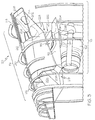
- the compartment based inlet particle separator system 120 includes a diffuser 202 and an inlet particle separator (IPS) 204.
- the diffuser 202 is disposed within the air inlet compartment 114 and has a diffuser inlet 206 and a diffuser outlet 208.
- the diffuser inlet 206 is coupled to receive ram air from the ram air inlet opening 118, and the diffuser outlet 208 is in fluid communication with the air inlet compartment 114.
- the diffuser 202 is configured to reduce the velocity of the ram air that flows into the ram air inlet opening 118, and discharge the ram air, via the diffuser outlet 208, into the air inlet compartment 114. The reduced velocity reduces the loss in pressure of the ram air as it dumps from diffuser outlet 208 to air inlet compartment 114.
- the diffuser 202 may be variously disposed, but in the depicted embodiment it is disposed as close as possible to the wall (not illustrated) of the tailcone 102, while still allowing room from the structural ribs 212.
- the inlet door actuator 124 which is also not depicted in FIG. 2 , is preferably disposed in the opening 214 in the diffuser 202.
- the diffuser 202 is preferably configured as a transverse diffuser.
- the diffuser 202 includes an inner surface 216 that defines a cross sectional flow area that increases between the diffuser inlet 206 and the diffuser outlet 208. The increase in flow area is transverse to the external flow momentum.
- the diffuser 202 is additionally configured such that it has a first height and a first width adjacent to the diffuser inlet 206, and transitions to a second height and a second width adjacent to the diffuser outlet 208, where the first height is greater than the second height, and the first width is less than the second width.
- the IPS 204 is also disposed within the air inlet compartment 114. More specifically, it is disposed between the diffuser outlet 208 and the APU air inlet port 115, and divides the air inlet compartment 114 into two sections - a non-filtered section 218 and a filtered section 222.
- the non-filtered section 218 receives the ram air discharged from the diffuser 202
- the filtered section 222 receives filtered air discharged from the IPS 204.
- the IPS may be implemented using any one of numerous known IPSs that are configured to remove relatively fine dust particles (e.g., ⁇ 30 ⁇ m) and larger particles from the air discharged from the diffuser 202.
- suitable IPSs include vortex panels, barrier filters, and multi-channel particle separators (MCPSs).
- the IPS 204 is preferably disposed beneath the diffuser 202 and intercepts the airflow as it reverses direction inside the non-filtered section 218 of the air inlet compartment 114.
- the embodiment depicted in FIG. X illustrates how either a plurality of vortex panels or a plurality barrier filters are preferably disposed in the air inlet compartment.
- the vortex panels or barrier filters occupy the entire space below the diffuser 202 and above the separation barrier wall 112, and extend the entirety of the non-filtered section 218 of the air inlet compartment 114 from side wall to side wall (for clarity, the sidewalls are not depicted).
- the region that is not occupied by the IPS 204 includes a wall 224 to ensure all of the ram air discharged from the diffuser 202 flow through the IPS 204.
- the type of barrier filters may be either non-self-cleaning or self-cleaning. If non-self-cleaning barrier filters are used, the filters should be periodically checked, removed, and cleaned. Self-cleaning barrier filters are less desirable since this type of IPS 204 will typically occupy more space due to the additional hardware needed to implement the self-cleaning functionality.
- the vortex panel and barrier filter configurations require approximately the same amount of surface area to keep pressure losses to a minimum, and are thus very similar in size. As such, both configurations are illustrated using FIG. 2 .
- the MCPSs exhibit relatively lower pressure losses as compared to the vortex panels or barrier filters. Consequently, and as depicted in FIG. 3 , when the IPS 204 is implemented using MCPSs, the IPS 204 is smaller as compared to the other two types of IPSs 204. It will be appreciated that the MCPSs can be disposed in a horizontal or vertical arrangement. Though not depicted in FIG.
- the region that is not occupied by the IPS 204 includes the wall 224 to ensure all of the ram air discharged from the diffuser 202 flow through the IPS 204.
- a bellmouth structure 226 extends from the APU inlet port 115 into the air inlet compartment 114.
- the bellmouth structure 226 is preferably coupled to the APU inlet duct 126, and is configured to minimize losses as air flows into the APU inlet duct 126.
- the bellmouth structure 226 is preferably disposed above the separation barrier wall 112 to prevent any particles or FOD (foreign object debris) that may be lying on the separation barrier wall 112 to be sucked into the APU 128.
- FIGS. 2 and 3 An APU compartment cooling duct 228 is also depicted in FIGS. 2 and 3 .
- the APU compartment cooling duct 228 includes a cooling air inlet 232 and a cooling air outlet 234, and extends through the separation barrier wall 112.
- the cooling air inlet 232 is in fluid communication with the ram air inlet opening 118
- the cooling air outlet 234 is in fluid communication with the APU compartment 116.
- ambient air is drawn into the APU compartment 116 to provide APU compartment and oil cooling air, which is drawn via a non-illustrated APU exhaust eductor system.
- the compartment based inlet particle separator systems 120 depicted and described herein exhibit relatively low pressure loss, the systems nonetheless do exhibit some pressure loss.
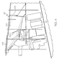
- the compartment based inlet particle separator system 120 additionally implements a bypass function.
- the diffuser 202 additionally includes a bypass port 402.
- the bypass port 402 is disposed between the diffuser inlet 206 and the diffuser outlet 208, and is in fluid communication with the APU air inlet port 115.
- the system 120 additionally includes a plurality of flow control surfaces 404 (404-1, 404-2).
- the flow control surfaces 404 are rotationally mounted within the diffuser 202 and are movable between a first position and a second position. In the first position, which is the position depicted in FIG. 4 , the flow control surfaces 404 direct ram air through the bypass port 402 and directly into the APU air inlet port 115. In the second position, which is the position depicted in FIG. 5 , the flow control surfaces 404 direct the ram air through the diffuser outlet 208, through the IPS 204, and into the APU air inlet port 115. Though not depicted in FIGS. 4 and 5 , the flow control surfaces 404 may be moved via the inlet door actuator 124 or a separate, non-illustrated actuator.
Landscapes
- Engineering & Computer Science (AREA)
- Aviation & Aerospace Engineering (AREA)
- Chemical & Material Sciences (AREA)
- Combustion & Propulsion (AREA)
- Mechanical Engineering (AREA)
- General Engineering & Computer Science (AREA)
- Separating Particles In Gases By Inertia (AREA)
- Cyclones (AREA)
Description
- The present invention generally relates to inlet particle separator systems for auxiliary power units (APUs), and more particularly relates to compartment based inlet particle separator systems for aircraft that include an APU system compartment.
- In many aircraft, the main propulsion engines not only provide propulsion for the aircraft, but may also be used to drive various other rotating components such as, for example, generators, compressors, and pumps, to thereby supply electrical and/or pneumatic power. However, when an aircraft is on the ground, its main engines may not be operating. Moreover, in some instances the main propulsion engines may not be capable of supplying the power needed for propulsion as well as the power to drive these other rotating components. Thus, many aircraft include an auxiliary power unit (APU) to supplement the main propulsion engines in providing electrical and/or pneumatic power. An APU may also be used to start the propulsion engines.
- Many APU-equipped aircraft are operated in environments that have a high concentration of fine dust particles (e.g., < 30 µm) suspended in the air. These fine dust particles, when ingested by the APU, can adversely impact the APU. For example, the fine dust particles can plug the holes in effusion cooled combustors, and can plug and corrode the high temperature turbine passages and hardware. To alleviate the adverse impact of dust particles, many aircraft include an inlet particle separator system (IPS).
- Most IPSs are designed to separate out relatively large particles (e.g., 100 µm < 1000 µm) but are less efficient at separating out fine particles. This is because these systems typically rely on particle inertia to move the particles into a separate collector and scavenge system. Fine particles, with relatively lower inertia, are much more inclined to follow the inlet airflow into the gas turbine engine, resulting in low separation efficiencies. Thus, many aircraft additionally include one or more systems to remove these fine particles. These additional systems include barrier filters (self-cleaning and non-self-cleaning), vortex panels, and multi-channel particle separator (MCPS) systems.
- Although the three particle separator systems just mentioned do excel at removing fine particles from APU inlet airflow, they all exhibit certain drawbacks. In particular, each is designed to be relatively large in size in order to minimize pressure losses. This size requirement negates the ability to mount these systems outside of the aircraft or inside the already existing APU inlet duct system.
- Hence, there is a need for a particle separator system that can remove fine dust particles from APU inlet airflow, exhibit minimal pressure losses, and be incorporated into the APU air inlet system. The present invention addresses at least this need.
- This summary is provided to describe select concepts in a simplified form that are further described in the Detailed Description. This summary is not intended to identify key or essential features of the claimed subject matter, nor is it intended to be used as an aid in determining the scope of the claimed subject matter.
- In one embodiment, a compartment based inlet particle separator system for an aircraft that includes an auxiliary power unit (APU) system compartment, includes a separation barrier wall, a ram air inlet opening, a diffuser, and an inlet particle separator (IPS). The separation barrier wall is disposed within the APU system compartment and is configured to divide the APU system compartment into an air inlet compartment and an APU compartment. The separation barrier wall has an APU air inlet port formed therein that provides fluid communication between the air inlet compartment and the APU compartment. The ram air inlet opening is formed in the air inlet compartment for receiving a flow of ram air. The diffuser is disposed within the air inlet compartment and has a diffuser inlet and a diffuser outlet. The diffuser inlet is coupled to receive ram air from the ram air inlet opening. The diffuser outlet is in fluid communication with, and is configured to discharge ram air into, the air inlet compartment. The IPS is disposed within the air inlet compartment between the diffuser outlet and the APU air inlet port.
- In another embodiment, an auxiliary power unit (APU) air inlet system for an aircraft that includes an APU system compartment includes a separation barrier wall, a ram air inlet opening, a diffuser, a plurality of flow control surfaces, and an inlet particle separator (IPS). The separation barrier wall is disposed within the APU system compartment and is configured to divide the APU system compartment into an air inlet compartment and an APU compartment. The separation barrier wall has an APU air inlet port formed therein that provides fluid communication between the air inlet compartment and the APU compartment. The ram air inlet opening is formed in the air inlet compartment for receiving a flow of ram air. The diffuser is disposed within the air inlet compartment and has a diffuser inlet, a diffuser outlet, and a bypass port disposed between the diffuser inlet and the diffuser outlet. The diffuser inlet is coupled to receive ram air from the ram air inlet opening. The diffuser outlet is in fluid communication with, and is configured to discharge ram air into, the air inlet compartment. The bypass port is in fluid communication with the APU air inlet port. The flow control surfaces are rotationally mounted within the diffuser and are movable between a first position, in which the flow control surfaces direct ram air through the bypass port and into the APU air inlet port, and a second position, in which the flow control surfaces direct ram air through the diffuser outlet. The inlet particle separator (IPS) is disposed within the air inlet compartment between the diffuser outlet and the APU air inlet port.
- In yet another embodiment, an auxiliary power unit (APU) air inlet system for an aircraft that includes an APU system compartment includes a separation barrier wall, a ram air inlet opening, a transverse diffuser, an inlet particle separator (IPS), and an APU. The separation barrier wall is disposed within the APU system compartment and is configured to divide the APU system compartment into an air inlet compartment and an APU compartment. The separation barrier wall has an APU air inlet port formed therein that provides fluid communication between the air inlet compartment and the APU compartment. The ram air inlet opening is formed in the air inlet compartment for receiving a flow of ram air. The transverse diffuser is disposed within the air inlet compartment and has a diffuser inlet and a diffuser outlet. The diffuser inlet is coupled to receive ram air from the ram air inlet opening. The diffuser outlet is in fluid communication with, and is configured to discharge ram air into, the air inlet compartment. The IPS is disposed within the air inlet compartment between the diffuser outlet and the APU air inlet port. The APU is disposed within the APU compartment, and has an air inlet in fluid communication with the APU air inlet port.
- Furthermore, other desirable features and characteristics of the compartment based inlet particle separator system will become apparent from the subsequent detailed description and the appended claims, taken in conjunction with the accompanying drawings and the preceding background.
- The present invention will hereinafter be described in conjunction with the following drawing figures, wherein like numerals denote like elements, and wherein:
-
FIG. 1 depicts a simplified cross-sectional schematic of a tail cone portion of an aircraft; -
FIGS. 2 and3 depict example embodiments of compartment based inlet particle separator systems that may be implemented in the aircraft depicted inFIG. 1 ; -
FIGS. 4 and5 depict another example embodiment of a compartment based inlet particle separator system that may be implemented in the aircraft depicted inFIG. 1 . - The following detailed description is merely exemplary in nature and is not intended to limit the invention or the application and uses of the invention. As used herein, the word "exemplary" means "serving as an example, instance, or illustration." Thus, any embodiment described herein as "exemplary" is not necessarily to be construed as preferred or advantageous over other embodiments. All of the embodiments described herein are exemplary embodiments provided to enable persons skilled in the art to make or use the invention and not to limit the scope of the invention which is defined by the claims. Furthermore, there is no intention to be bound by any expressed or implied theory presented in the preceding technical field, background, brief summary, or the following detailed description.
- Turning now to
FIG. 1 , a cross-sectional schematic of a tail cone portion of anaircraft 100 is depicted. Theaircraft 100 includes an auxiliary power unit (APU)system compartment 102 that is defined by anexterior surface 104, aforward firewall 106, and anaft firewall 108. As is generally known, theforward firewall 106 separates theAPU system compartment 102 from other sections of theaircraft 100. In the depicted embodiment, theAPU system compartment 102 is formed in the tailcone section of theaircraft 100. It will be appreciated, however, that this is merely exemplary, and that theAPU system compartment 102 could be formed in any one of numerous other sections of theaircraft 100. It will additionally be appreciated that, depending on its location in theaircraft 100, theAPU system compartment 102 may be defined by only oneforward firewall 106 oraft firewall 108. - No matter its specific location, the
APU system compartment 102 additionally includes aseparation barrier wall 112. Theseparation barrier wall 112 extends between theforward firewall 106 and theaft firewall 108, and divides theAPU system compartment 102 into two separate compartments - anair inlet compartment 114 and anAPU compartment 116. AsFIG. 1 also depicts, theseparation barrier wall 112 has an APUair inlet port 115 formed therein that provides fluid communication between theair inlet compartment 114 and an inlet to anAPU 128. - As
FIG. 1 also depicts, a ramair inlet opening 118 is formed in theair inlet compartment 114 and extends through theexterior surface 104 of theaircraft 100. As is generally known, the ramair inlet opening 118 is configured to selectively receive a flow of ram air. To facilitate this, aninlet door 122 and aninlet door actuator 124 are also preferably coupled to theAPU system compartment 102. Theinlet door 122 is coupled to receive an actuation drive force from theinlet door actuator 124 and is configured, in response to the actuation drive force, to move between a closed position and a plurality of open positions. In the closed position, theinlet door 122 prevents ram air from flowing into the ramair inlet opening 118. Conversely, in any one of the plurality of open positions, ram air may flow into the ramair inlet opening 118. - As
FIG. 1 further depicts, a compartment based inletparticle separator system 120 is disposed within theair inlet compartment 114, and anAPU 128 is disposed within theAPU compartment 116. A more detailed representation of example physical embodiments of the compartment based inletparticle separator system 120 are depicted inFIGS. 2 and3 , and will momentarily be described. Before doing so, however, it is noted that theAPU 128 has anair inlet 127 that is in fluid communication with the APUair inlet port 115 via anAPU inlet duct 126 that extends from theAPU 128. - Turning now to
FIG. 2 , the compartment based inletparticle separator system 120 includes adiffuser 202 and an inlet particle separator (IPS) 204. Thediffuser 202 is disposed within theair inlet compartment 114 and has adiffuser inlet 206 and adiffuser outlet 208. Thediffuser inlet 206 is coupled to receive ram air from the ramair inlet opening 118, and thediffuser outlet 208 is in fluid communication with theair inlet compartment 114. Thediffuser 202 is configured to reduce the velocity of the ram air that flows into the ramair inlet opening 118, and discharge the ram air, via thediffuser outlet 208, into theair inlet compartment 114. The reduced velocity reduces the loss in pressure of the ram air as it dumps fromdiffuser outlet 208 toair inlet compartment 114. - The
diffuser 202 may be variously disposed, but in the depicted embodiment it is disposed as close as possible to the wall (not illustrated) of thetailcone 102, while still allowing room from thestructural ribs 212. Theinlet door actuator 124, which is also not depicted inFIG. 2 , is preferably disposed in theopening 214 in thediffuser 202. - The
diffuser 202 is preferably configured as a transverse diffuser. In this regard, thediffuser 202 includes aninner surface 216 that defines a cross sectional flow area that increases between thediffuser inlet 206 and thediffuser outlet 208. The increase in flow area is transverse to the external flow momentum. Thediffuser 202 is additionally configured such that it has a first height and a first width adjacent to thediffuser inlet 206, and transitions to a second height and a second width adjacent to thediffuser outlet 208, where the first height is greater than the second height, and the first width is less than the second width. As a result, the diffusion efficiency is improved, and the risk of flow separation within thediffuser 202 is significantly reduced. This is achieved by "squeezing" the flow of ram air through the reduced height and into the increased width. Thus, by the time the ram air is discharged from thediffuser outlet 208 and into theair inlet compartment 114, its velocity has been sufficiently slowed so that the pressure loss associated with the dump is minimal. - The
IPS 204 is also disposed within theair inlet compartment 114. More specifically, it is disposed between thediffuser outlet 208 and the APUair inlet port 115, and divides theair inlet compartment 114 into two sections - anon-filtered section 218 and a filteredsection 222. Thenon-filtered section 218 receives the ram air discharged from thediffuser 202, and the filteredsection 222 receives filtered air discharged from theIPS 204. It will be appreciated that the IPS may be implemented using any one of numerous known IPSs that are configured to remove relatively fine dust particles (e.g., < 30 µm) and larger particles from the air discharged from thediffuser 202. Some non-limiting examples of suitable IPSs include vortex panels, barrier filters, and multi-channel particle separators (MCPSs). - Regardless of the
specific IPS 204 that is used, theIPS 204 is preferably disposed beneath thediffuser 202 and intercepts the airflow as it reverses direction inside thenon-filtered section 218 of theair inlet compartment 114. The embodiment depicted in FIG. X illustrates how either a plurality of vortex panels or a plurality barrier filters are preferably disposed in the air inlet compartment. Preferably, the vortex panels or barrier filters occupy the entire space below thediffuser 202 and above theseparation barrier wall 112, and extend the entirety of thenon-filtered section 218 of theair inlet compartment 114 from side wall to side wall (for clarity, the sidewalls are not depicted). This ensures that all of the ram air discharged from thediffuser 202 passes through theIPS 204. Moreover, the region that is not occupied by the IPS 204 (e.g., the region above the diffuser 204) includes awall 224 to ensure all of the ram air discharged from thediffuser 202 flow through theIPS 204. - It should be noted that when the
IPS 204 is implemented using a plurality of barrier filters, the type of barrier filters may be either non-self-cleaning or self-cleaning. If non-self-cleaning barrier filters are used, the filters should be periodically checked, removed, and cleaned. Self-cleaning barrier filters are less desirable since this type ofIPS 204 will typically occupy more space due to the additional hardware needed to implement the self-cleaning functionality. - The vortex panel and barrier filter configurations require approximately the same amount of surface area to keep pressure losses to a minimum, and are thus very similar in size. As such, both configurations are illustrated using
FIG. 2 . However, the MCPSs exhibit relatively lower pressure losses as compared to the vortex panels or barrier filters. Consequently, and as depicted inFIG. 3 , when theIPS 204 is implemented using MCPSs, theIPS 204 is smaller as compared to the other two types ofIPSs 204. It will be appreciated that the MCPSs can be disposed in a horizontal or vertical arrangement. Though not depicted inFIG. 3 , it will be appreciated that the region that is not occupied by the IPS 204 (e.g., the region above the diffuser 204) includes thewall 224 to ensure all of the ram air discharged from thediffuser 202 flow through theIPS 204. - As
FIGS. 2 and3 additionally depict, abellmouth structure 226 extends from theAPU inlet port 115 into theair inlet compartment 114. Thebellmouth structure 226 is preferably coupled to theAPU inlet duct 126, and is configured to minimize losses as air flows into theAPU inlet duct 126. Thebellmouth structure 226 is preferably disposed above theseparation barrier wall 112 to prevent any particles or FOD (foreign object debris) that may be lying on theseparation barrier wall 112 to be sucked into theAPU 128. - An APU
compartment cooling duct 228 is also depicted inFIGS. 2 and3 . The APUcompartment cooling duct 228 includes a coolingair inlet 232 and a coolingair outlet 234, and extends through theseparation barrier wall 112. The coolingair inlet 232 is in fluid communication with the ramair inlet opening 118, and the coolingair outlet 234 is in fluid communication with theAPU compartment 116. Thus, whenever theinlet door 122 is in an open position, ambient air is drawn into theAPU compartment 116 to provide APU compartment and oil cooling air, which is drawn via a non-illustrated APU exhaust eductor system. - There may be instances in which
aircraft 100 may only operate part-time environments with a heavy concentration of suspended particulate in the air. As such, theAPUs 122 in theseaircraft 100 may only operate part-time in these environments. Although the compartment based inletparticle separator systems 120 depicted and described herein exhibit relatively low pressure loss, the systems nonetheless do exhibit some pressure loss. Thus, in some embodiments, such as the one depicted inFIGS. 4 and5 , the compartment based inletparticle separator system 120 additionally implements a bypass function. To facilitate this function, thediffuser 202 additionally includes abypass port 402. Thebypass port 402 is disposed between thediffuser inlet 206 and thediffuser outlet 208, and is in fluid communication with the APUair inlet port 115. - The
system 120 additionally includes a plurality of flow control surfaces 404 (404-1, 404-2). The flow control surfaces 404 are rotationally mounted within thediffuser 202 and are movable between a first position and a second position. In the first position, which is the position depicted inFIG. 4 , the flow control surfaces 404 direct ram air through thebypass port 402 and directly into the APUair inlet port 115. In the second position, which is the position depicted inFIG. 5 , the flow control surfaces 404 direct the ram air through thediffuser outlet 208, through theIPS 204, and into the APUair inlet port 115. Though not depicted inFIGS. 4 and5 , the flow control surfaces 404 may be moved via theinlet door actuator 124 or a separate, non-illustrated actuator. - In this document, relational terms such as first and second, and the like may be used solely to distinguish one entity or action from another entity or action without necessarily requiring or implying any actual such relationship or order between such entities or actions. Numerical ordinals such as "first," "second," "third," etc. simply denote different singles of a plurality and do not imply any order or sequence unless specifically defined by the claim language. The sequence of the text in any of the claims does not imply that process steps must be performed in a temporal or logical order according to such sequence unless it is specifically defined by the language of the claim. The process steps may be interchanged in any order without departing from the scope of the invention as long as such an interchange does not contradict the claim language and is not logically nonsensical.
- Furthermore, depending on the context, words such as "connect" or "coupled to" used in describing a relationship between different elements do not imply that a direct physical connection must be made between these elements. For example, two elements may be connected to each other physically, electronically, logically, or in any other manner, through one or more additional elements.
- While at least one exemplary embodiment has been presented in the foregoing detailed description of the invention, it should be appreciated that a vast number of variations exist. It should also be appreciated that the exemplary embodiment or exemplary embodiments are only examples, and are not intended to limit the scope, applicability, or configuration of the invention in any way. Rather, the foregoing detailed description will provide those skilled in the art with a convenient road map for implementing an exemplary embodiment of the invention. It being understood that various changes may be made in the function and arrangement of elements described in an exemplary embodiment without departing from the scope of the invention as set forth in the appended claims.
Claims (12)
- A compartment based inlet particle separator system for an aircraft that includes an auxiliary power unit (APU) system compartment, the system comprising:a separation barrier wall disposed within the APU system compartment and configured to divide the APU system compartment into an air inlet compartment and an APU compartment, the separation barrier wall having an APU air inlet port formed therein that provides fluid communication between the air inlet compartment and the APU compartment;a ram air inlet opening formed in the air inlet compartment for receiving a flow of ram air;a diffuser disposed within the air inlet compartment and having a diffuser inlet and a diffuser outlet, the diffuser inlet coupled to receive ram air from the ram air inlet opening, the diffuser outlet in fluid communication with, and configured to discharge ram air into, the air inlet compartment; andan inlet particle separator (IPS) disposed within the air inlet compartment between the diffuser outlet and the APU air inlet port.
- The system of claim 1, wherein:the IPS system divides the air inlet compartment into a non-filtered section and a filtered section;the non-filtered section receives the ram air discharged from the diffuser; andthe filtered section receives filtered air discharged from the IPS system.
- The system of claim 1, wherein the IPS comprises a plurality of vortex panels.
- The system of claim 1, wherein the IPS comprises a plurality of barrier filters.
- The system of claim 4, wherein the barrier filters are configured as self-cleaning barrier filters.
- The system of claim 1, wherein the IPS comprises a multi-channel particle separator (MCPS) system.
- The system of claim 1, further comprising:a bellmouth structure extending from the APU air inlet port into the air inlet compartment.
- The system of claim 1, wherein the diffuser is configured as a transverse diffuser.
- The system of claim 8, wherein:the diffuser has an inner surface that defines a cross sectional flow area; andthe cross sectional flow area increases between the diffuser inlet and the diffuser outlet.
- The system of claim 8, wherein:the diffuser has a first height and a first width adjacent the diffuser inlet and a second height and a second width adjacent the diffuser outlet;the first height is greater than the second height; andthe first width is less than the second width.
- The system of claim 1, further comprising:an APU compartment cooling duct including a cooling air inlet and a cooling air outlet and extending through the separation barrier wall, the cooling air inlet in fluid communication with the ram air inlet opening, the cooling air outlet in fluid communication with the APU compartment.
- The system of claim 1, wherein the diffuser further comprises a bypass port disposed between the diffuser inlet and the diffuser outlet, the bypass port in fluid communication with the APU air inlet port, and wherein the system further comprises:a plurality of flow control surfaces rotationally mounted within the diffuser and movable between a first position, in which the flow control surfaces direct ram air through the bypass port and into the APU air inlet port, and a second position, in which the flow control surfaces direct ram air through the diffuser outlet.
Applications Claiming Priority (1)
| Application Number | Priority Date | Filing Date | Title |
|---|---|---|---|
| US14/573,926 US9719352B2 (en) | 2014-12-17 | 2014-12-17 | Compartment based inlet particle separator system |
Publications (2)
| Publication Number | Publication Date |
|---|---|
| EP3034408A1 true EP3034408A1 (en) | 2016-06-22 |
| EP3034408B1 EP3034408B1 (en) | 2017-04-05 |
Family
ID=54848510
Family Applications (1)
| Application Number | Title | Priority Date | Filing Date |
|---|---|---|---|
| EP15199431.6A Not-in-force EP3034408B1 (en) | 2014-12-17 | 2015-12-10 | Compartment based inlet particle separator system |
Country Status (2)
| Country | Link |
|---|---|
| US (1) | US9719352B2 (en) |
| EP (1) | EP3034408B1 (en) |
Cited By (5)
| Publication number | Priority date | Publication date | Assignee | Title |
|---|---|---|---|---|
| US20160177724A1 (en) * | 2014-12-17 | 2016-06-23 | Honeywell International Inc. | Compartment based inlet particle separator system |
| EP3309077A1 (en) * | 2016-10-14 | 2018-04-18 | Pratt & Whitney Canada Corp. | Auxiliary power unit inlet assembly with particle separator |
| US10279920B1 (en) * | 2018-02-27 | 2019-05-07 | Brant Farrell | Foreign object debris barrier filter apparatus for an aircraft intake system |
| US10508626B2 (en) | 2016-10-14 | 2019-12-17 | Pratt & Whitney Canada Corp. | Auxiliary power unit inlet assembly with filter |
| US10513344B2 (en) | 2016-10-14 | 2019-12-24 | Pratt & Whitney Canada Corp. | Auxiliary power unit assembly with removable inlet filter |
Families Citing this family (8)
| Publication number | Priority date | Publication date | Assignee | Title |
|---|---|---|---|---|
| ES2890374T3 (en) * | 2017-10-30 | 2022-01-18 | Airbus Operations Sl | Aircraft tail cone incorporating an APU with annular air intake |
| US11634228B2 (en) * | 2017-11-01 | 2023-04-25 | Sikorsky Aircraft Corporation | High volume flow management of cooling air |
| US11111024B2 (en) | 2018-01-12 | 2021-09-07 | Honeywell International Inc. | Foldable RAM air inlet filter |
| US11085372B2 (en) * | 2018-07-18 | 2021-08-10 | The Boeing Company | Anti-ice system exhaust air disruptor |
| US10865711B2 (en) | 2018-08-03 | 2020-12-15 | Pratt & Whitney Canada Corp. | Air inlet system for auxiliary power units |
| US10906660B2 (en) * | 2018-08-09 | 2021-02-02 | Bell Textron Inc. | Cowling inlet for sideward airflow |
| CN113950576A (en) | 2019-03-29 | 2022-01-18 | 唐纳森公司 | Air cleaner bypass assembly and method of operation |
| US11111855B2 (en) | 2019-05-23 | 2021-09-07 | Rolls-Royce North American Technologies Inc. | Inlet particle separator |
Citations (3)
| Publication number | Priority date | Publication date | Assignee | Title |
|---|---|---|---|---|
| EP1686058A1 (en) * | 2005-01-27 | 2006-08-02 | Honeywell International Inc. | Aircraft inlet assembly for reducing auxiliary power unit noise |
| EP1847458A2 (en) * | 2006-04-20 | 2007-10-24 | Honeywell Inc. | Diffusing air inlet door assembly |
| WO2010077241A1 (en) * | 2008-12-30 | 2010-07-08 | Sikorsky Aircraft Corporation | Engine air particle separator |
Family Cites Families (30)
| Publication number | Priority date | Publication date | Assignee | Title |
|---|---|---|---|---|
| US3449891A (en) | 1966-11-15 | 1969-06-17 | United Aircraft Corp | Engine inlet air particle separator |
| US3421296A (en) * | 1966-11-15 | 1969-01-14 | United Aircraft Corp | Engine inlet air particle separator |
| US3673771A (en) * | 1970-11-23 | 1972-07-04 | Avco Corp | Multi-channel particle separator |
| US3952972A (en) | 1974-12-24 | 1976-04-27 | United Aircraft Of Canada Limited | Inertial separator |
| DE2605941C3 (en) | 1976-02-14 | 1980-10-30 | Mtu Motoren- Und Turbinen-Union Friedrichshafen Gmbh, 7990 Friedrichshafen | casing |
| US4250703A (en) | 1979-03-15 | 1981-02-17 | Avco Corporation | Swinging door particle separator and deicing system |
| US4304094A (en) | 1979-11-16 | 1981-12-08 | United Technologies Corp. | Engine air particle separator for use with gas turbine engine |
| US6264137B1 (en) | 2000-02-25 | 2001-07-24 | Honeywell International Inc. | Inlet vortex bustor and ice protector for auxiliary power units |
| US6595742B2 (en) * | 2000-10-02 | 2003-07-22 | Westar Corporation | Aircraft engine air filter and method |
| US6520738B2 (en) | 2001-03-15 | 2003-02-18 | Honeywell International, Inc. | Plenum entry bulk swirl generator |
| US6651929B2 (en) | 2001-10-29 | 2003-11-25 | Pratt & Whitney Canada Corp. | Passive cooling system for auxiliary power unit installation |
| DE10200459A1 (en) * | 2002-01-09 | 2003-07-24 | Airbus Gmbh | Air intake for an auxiliary engine in an aircraft |
| US6824582B2 (en) | 2002-12-13 | 2004-11-30 | Westar Corporation | Filter system for turbine engine |
| US20060059891A1 (en) * | 2004-09-23 | 2006-03-23 | Honeywell International, Inc. | Quiet chevron/tab exhaust eductor system |
| US7344107B2 (en) * | 2004-10-26 | 2008-03-18 | The Boeing Company | Dual flow APU inlet and associated systems and methods |
| ES2273546B1 (en) | 2004-12-31 | 2008-03-16 | Airbus España, S.L. | ADMISSION CONDUCT FOR AN AUXILIARY ELECTROGEN GROUP WITH AEROACUSTIC GUIDING FINS. |
| US7600713B2 (en) * | 2005-03-04 | 2009-10-13 | Honeywell International Inc. | Pre-hung inlet door system |
| US7966825B2 (en) * | 2006-10-31 | 2011-06-28 | Honeywell International Inc. | Exhaust eductor system with a recirculation baffle |
| US20080152500A1 (en) | 2006-12-20 | 2008-06-26 | Carsten Mehring | Inertial particle separator for compressor shroud bleed |
| US7678165B2 (en) | 2006-12-28 | 2010-03-16 | General Electric Company | Particle separator using boundary layer control |
| EP2282031B1 (en) | 2009-07-02 | 2012-06-06 | Eurocopter Deutschland GmbH | Filtering device with integrated bypass for an air inlet |
| US8444083B2 (en) * | 2011-06-30 | 2013-05-21 | Hamilton Sundstrand Corporation | Auxiliary power unit inlet |
| US9254924B2 (en) * | 2011-08-12 | 2016-02-09 | Hamilton Sundstrand Corporation | Pressure influencing assembly for an aircraft auxiliary system |
| US20140202121A1 (en) * | 2012-06-18 | 2014-07-24 | Hamilton Sundstrand Corporation | Conical light fod momentum particle separator protector |
| US9314723B2 (en) * | 2012-09-17 | 2016-04-19 | Honeywell International Inc. | Inlet particle separator systems and methods |
| US9500129B2 (en) | 2012-10-29 | 2016-11-22 | Honeywell International Inc. | Turboshaft engines having improved inlet particle scavenge systems and methods for the manufacture thereof |
| US20140182306A1 (en) * | 2012-12-28 | 2014-07-03 | United Technologies Corporation | Filter for aircraft apu system |
| US20140260127A1 (en) * | 2013-03-15 | 2014-09-18 | Aerospace Filtration Systems, Inc. | Interchangeable inlet protection systems for air intakes of aircraft engines and related method |
| US9377030B2 (en) | 2013-03-29 | 2016-06-28 | Honeywell International Inc. | Auxiliary power units and other turbomachines having ported impeller shroud recirculation systems |
| US9719352B2 (en) * | 2014-12-17 | 2017-08-01 | Honeywell International Inc. | Compartment based inlet particle separator system |
-
2014
- 2014-12-17 US US14/573,926 patent/US9719352B2/en active Active
-
2015
- 2015-12-10 EP EP15199431.6A patent/EP3034408B1/en not_active Not-in-force
Patent Citations (3)
| Publication number | Priority date | Publication date | Assignee | Title |
|---|---|---|---|---|
| EP1686058A1 (en) * | 2005-01-27 | 2006-08-02 | Honeywell International Inc. | Aircraft inlet assembly for reducing auxiliary power unit noise |
| EP1847458A2 (en) * | 2006-04-20 | 2007-10-24 | Honeywell Inc. | Diffusing air inlet door assembly |
| WO2010077241A1 (en) * | 2008-12-30 | 2010-07-08 | Sikorsky Aircraft Corporation | Engine air particle separator |
Cited By (7)
| Publication number | Priority date | Publication date | Assignee | Title |
|---|---|---|---|---|
| US20160177724A1 (en) * | 2014-12-17 | 2016-06-23 | Honeywell International Inc. | Compartment based inlet particle separator system |
| US9719352B2 (en) * | 2014-12-17 | 2017-08-01 | Honeywell International Inc. | Compartment based inlet particle separator system |
| EP3309077A1 (en) * | 2016-10-14 | 2018-04-18 | Pratt & Whitney Canada Corp. | Auxiliary power unit inlet assembly with particle separator |
| US10508628B2 (en) | 2016-10-14 | 2019-12-17 | Pratt & Whitney Canada Corp. | Auxiliary power unit inlet assembly with particle separator |
| US10508626B2 (en) | 2016-10-14 | 2019-12-17 | Pratt & Whitney Canada Corp. | Auxiliary power unit inlet assembly with filter |
| US10513344B2 (en) | 2016-10-14 | 2019-12-24 | Pratt & Whitney Canada Corp. | Auxiliary power unit assembly with removable inlet filter |
| US10279920B1 (en) * | 2018-02-27 | 2019-05-07 | Brant Farrell | Foreign object debris barrier filter apparatus for an aircraft intake system |
Also Published As
| Publication number | Publication date |
|---|---|
| US20160177724A1 (en) | 2016-06-23 |
| EP3034408B1 (en) | 2017-04-05 |
| US9719352B2 (en) | 2017-08-01 |
Similar Documents
| Publication | Publication Date | Title |
|---|---|---|
| US9719352B2 (en) | Compartment based inlet particle separator system | |
| US8512450B2 (en) | Engine air particle separator | |
| US9631554B2 (en) | Electrostatic charge control inlet particle separator system | |
| EP1978222B1 (en) | Particle separator and debris control system | |
| US9546603B2 (en) | Engine systems and methods for removing particles from turbine air | |
| CN204755137U (en) | Ventilation intake pipe filth inertia separator | |
| CA2401649C (en) | Inlet vortex bustor and ice protector for auxiliary power units | |
| EP2743178B1 (en) | An air inlet combining a filter and a bypass device for use with a turbine engine | |
| EP2969764B1 (en) | Interchangeable inlet protection systems for air intakes of aircraft engines and related methods | |
| US9394827B2 (en) | Inlet particle separator system with flow passage through hub and/or shroud | |
| US4704145A (en) | Modular multi-channel particle separator | |
| US9863317B2 (en) | Filtering chamber and method for maintaining same | |
| US20140190347A1 (en) | Liquid injection inlet particle separator systems and methods | |
| EP3189880B1 (en) | Inlet particle separators system with high curvature hub | |
| CA2991340A1 (en) | Inertial particle separator for engine inlet | |
| EP2677140A2 (en) | Conical light fod momentum particle separator protector | |
| EP2737933A1 (en) | Inlet particle separator system with air injection | |
| EP2865599A1 (en) | Auxiliary power unit inlet door having openings formed therein | |
| CN110494359B (en) | Air intake unit for aircraft engine | |
| US10100734B2 (en) | Multi-channel particle separator | |
| CN210622926U (en) | Engine air intake system integrating sand prevention, anti-icing and bypass functions | |
| EP3309076B1 (en) | Auxiliary power unit inlet assembly with filter | |
| US7690595B2 (en) | System, method, and apparatus for throat corner scoop offtake for mixed compression inlets on aircraft engines | |
| EP3023330B1 (en) | Heat exchanger assembly for aircraft ecs | |
| EP3964699B1 (en) | Systems for interstage particle separation in multistage radial compressors of turbine engines |
Legal Events
| Date | Code | Title | Description |
|---|---|---|---|
| PUAI | Public reference made under article 153(3) epc to a published international application that has entered the european phase |
Free format text: ORIGINAL CODE: 0009012 |
|
| 17P | Request for examination filed |
Effective date: 20151210 |
|
| AK | Designated contracting states |
Kind code of ref document: A1 Designated state(s): AL AT BE BG CH CY CZ DE DK EE ES FI FR GB GR HR HU IE IS IT LI LT LU LV MC MK MT NL NO PL PT RO RS SE SI SK SM TR |
|
| AX | Request for extension of the european patent |
Extension state: BA ME |
|
| GRAP | Despatch of communication of intention to grant a patent |
Free format text: ORIGINAL CODE: EPIDOSNIGR1 |
|
| RIC1 | Information provided on ipc code assigned before grant |
Ipc: B64D 33/02 20060101AFI20161102BHEP Ipc: B64D 41/00 20060101ALI20161102BHEP |
|
| INTG | Intention to grant announced |
Effective date: 20161122 |
|
| GRAS | Grant fee paid |
Free format text: ORIGINAL CODE: EPIDOSNIGR3 |
|
| GRAA | (expected) grant |
Free format text: ORIGINAL CODE: 0009210 |
|
| AK | Designated contracting states |
Kind code of ref document: B1 Designated state(s): AL AT BE BG CH CY CZ DE DK EE ES FI FR GB GR HR HU IE IS IT LI LT LU LV MC MK MT NL NO PL PT RO RS SE SI SK SM TR |
|
| REG | Reference to a national code |
Ref country code: GB Ref legal event code: FG4D |
|
| REG | Reference to a national code |
Ref country code: CH Ref legal event code: EP |
|
| REG | Reference to a national code |
Ref country code: AT Ref legal event code: REF Ref document number: 881554 Country of ref document: AT Kind code of ref document: T Effective date: 20170415 |
|
| REG | Reference to a national code |
Ref country code: IE Ref legal event code: FG4D |
|
| REG | Reference to a national code |
Ref country code: DE Ref legal event code: R096 Ref document number: 602015002144 Country of ref document: DE |
|
| REG | Reference to a national code |
Ref country code: NL Ref legal event code: MP Effective date: 20170405 |
|
| REG | Reference to a national code |
Ref country code: LT Ref legal event code: MG4D |
|
| REG | Reference to a national code |
Ref country code: AT Ref legal event code: MK05 Ref document number: 881554 Country of ref document: AT Kind code of ref document: T Effective date: 20170405 |
|
| PG25 | Lapsed in a contracting state [announced via postgrant information from national office to epo] |
Ref country code: NL Free format text: LAPSE BECAUSE OF FAILURE TO SUBMIT A TRANSLATION OF THE DESCRIPTION OR TO PAY THE FEE WITHIN THE PRESCRIBED TIME-LIMIT Effective date: 20170405 |
|
| PG25 | Lapsed in a contracting state [announced via postgrant information from national office to epo] |
Ref country code: AT Free format text: LAPSE BECAUSE OF FAILURE TO SUBMIT A TRANSLATION OF THE DESCRIPTION OR TO PAY THE FEE WITHIN THE PRESCRIBED TIME-LIMIT Effective date: 20170405 Ref country code: HR Free format text: LAPSE BECAUSE OF FAILURE TO SUBMIT A TRANSLATION OF THE DESCRIPTION OR TO PAY THE FEE WITHIN THE PRESCRIBED TIME-LIMIT Effective date: 20170405 Ref country code: ES Free format text: LAPSE BECAUSE OF FAILURE TO SUBMIT A TRANSLATION OF THE DESCRIPTION OR TO PAY THE FEE WITHIN THE PRESCRIBED TIME-LIMIT Effective date: 20170405 Ref country code: NO Free format text: LAPSE BECAUSE OF FAILURE TO SUBMIT A TRANSLATION OF THE DESCRIPTION OR TO PAY THE FEE WITHIN THE PRESCRIBED TIME-LIMIT Effective date: 20170705 Ref country code: GR Free format text: LAPSE BECAUSE OF FAILURE TO SUBMIT A TRANSLATION OF THE DESCRIPTION OR TO PAY THE FEE WITHIN THE PRESCRIBED TIME-LIMIT Effective date: 20170706 Ref country code: FI Free format text: LAPSE BECAUSE OF FAILURE TO SUBMIT A TRANSLATION OF THE DESCRIPTION OR TO PAY THE FEE WITHIN THE PRESCRIBED TIME-LIMIT Effective date: 20170405 Ref country code: LT Free format text: LAPSE BECAUSE OF FAILURE TO SUBMIT A TRANSLATION OF THE DESCRIPTION OR TO PAY THE FEE WITHIN THE PRESCRIBED TIME-LIMIT Effective date: 20170405 |
|
| PG25 | Lapsed in a contracting state [announced via postgrant information from national office to epo] |
Ref country code: RS Free format text: LAPSE BECAUSE OF FAILURE TO SUBMIT A TRANSLATION OF THE DESCRIPTION OR TO PAY THE FEE WITHIN THE PRESCRIBED TIME-LIMIT Effective date: 20170405 Ref country code: PL Free format text: LAPSE BECAUSE OF FAILURE TO SUBMIT A TRANSLATION OF THE DESCRIPTION OR TO PAY THE FEE WITHIN THE PRESCRIBED TIME-LIMIT Effective date: 20170405 Ref country code: IS Free format text: LAPSE BECAUSE OF FAILURE TO SUBMIT A TRANSLATION OF THE DESCRIPTION OR TO PAY THE FEE WITHIN THE PRESCRIBED TIME-LIMIT Effective date: 20170805 Ref country code: LV Free format text: LAPSE BECAUSE OF FAILURE TO SUBMIT A TRANSLATION OF THE DESCRIPTION OR TO PAY THE FEE WITHIN THE PRESCRIBED TIME-LIMIT Effective date: 20170405 Ref country code: BG Free format text: LAPSE BECAUSE OF FAILURE TO SUBMIT A TRANSLATION OF THE DESCRIPTION OR TO PAY THE FEE WITHIN THE PRESCRIBED TIME-LIMIT Effective date: 20170705 Ref country code: SE Free format text: LAPSE BECAUSE OF FAILURE TO SUBMIT A TRANSLATION OF THE DESCRIPTION OR TO PAY THE FEE WITHIN THE PRESCRIBED TIME-LIMIT Effective date: 20170405 |
|
| REG | Reference to a national code |
Ref country code: DE Ref legal event code: R097 Ref document number: 602015002144 Country of ref document: DE |
|
| PG25 | Lapsed in a contracting state [announced via postgrant information from national office to epo] |
Ref country code: SK Free format text: LAPSE BECAUSE OF FAILURE TO SUBMIT A TRANSLATION OF THE DESCRIPTION OR TO PAY THE FEE WITHIN THE PRESCRIBED TIME-LIMIT Effective date: 20170405 Ref country code: RO Free format text: LAPSE BECAUSE OF FAILURE TO SUBMIT A TRANSLATION OF THE DESCRIPTION OR TO PAY THE FEE WITHIN THE PRESCRIBED TIME-LIMIT Effective date: 20170405 Ref country code: EE Free format text: LAPSE BECAUSE OF FAILURE TO SUBMIT A TRANSLATION OF THE DESCRIPTION OR TO PAY THE FEE WITHIN THE PRESCRIBED TIME-LIMIT Effective date: 20170405 Ref country code: DK Free format text: LAPSE BECAUSE OF FAILURE TO SUBMIT A TRANSLATION OF THE DESCRIPTION OR TO PAY THE FEE WITHIN THE PRESCRIBED TIME-LIMIT Effective date: 20170405 Ref country code: CZ Free format text: LAPSE BECAUSE OF FAILURE TO SUBMIT A TRANSLATION OF THE DESCRIPTION OR TO PAY THE FEE WITHIN THE PRESCRIBED TIME-LIMIT Effective date: 20170405 |
|
| PLBE | No opposition filed within time limit |
Free format text: ORIGINAL CODE: 0009261 |
|
| STAA | Information on the status of an ep patent application or granted ep patent |
Free format text: STATUS: NO OPPOSITION FILED WITHIN TIME LIMIT |
|
| PG25 | Lapsed in a contracting state [announced via postgrant information from national office to epo] |
Ref country code: IT Free format text: LAPSE BECAUSE OF FAILURE TO SUBMIT A TRANSLATION OF THE DESCRIPTION OR TO PAY THE FEE WITHIN THE PRESCRIBED TIME-LIMIT Effective date: 20170405 Ref country code: SM Free format text: LAPSE BECAUSE OF FAILURE TO SUBMIT A TRANSLATION OF THE DESCRIPTION OR TO PAY THE FEE WITHIN THE PRESCRIBED TIME-LIMIT Effective date: 20170405 |
|
| 26N | No opposition filed |
Effective date: 20180108 |
|
| PG25 | Lapsed in a contracting state [announced via postgrant information from national office to epo] |
Ref country code: SI Free format text: LAPSE BECAUSE OF FAILURE TO SUBMIT A TRANSLATION OF THE DESCRIPTION OR TO PAY THE FEE WITHIN THE PRESCRIBED TIME-LIMIT Effective date: 20170405 |
|
| REG | Reference to a national code |
Ref country code: IE Ref legal event code: MM4A |
|
| PG25 | Lapsed in a contracting state [announced via postgrant information from national office to epo] |
Ref country code: MT Free format text: LAPSE BECAUSE OF NON-PAYMENT OF DUE FEES Effective date: 20171210 Ref country code: LU Free format text: LAPSE BECAUSE OF NON-PAYMENT OF DUE FEES Effective date: 20171210 |
|
| REG | Reference to a national code |
Ref country code: FR Ref legal event code: ST Effective date: 20180831 |
|
| REG | Reference to a national code |
Ref country code: BE Ref legal event code: MM Effective date: 20171231 |
|
| PG25 | Lapsed in a contracting state [announced via postgrant information from national office to epo] |
Ref country code: FR Free format text: LAPSE BECAUSE OF NON-PAYMENT OF DUE FEES Effective date: 20180102 Ref country code: IE Free format text: LAPSE BECAUSE OF NON-PAYMENT OF DUE FEES Effective date: 20171210 |
|
| PG25 | Lapsed in a contracting state [announced via postgrant information from national office to epo] |
Ref country code: BE Free format text: LAPSE BECAUSE OF NON-PAYMENT OF DUE FEES Effective date: 20171231 |
|
| PG25 | Lapsed in a contracting state [announced via postgrant information from national office to epo] |
Ref country code: HU Free format text: LAPSE BECAUSE OF FAILURE TO SUBMIT A TRANSLATION OF THE DESCRIPTION OR TO PAY THE FEE WITHIN THE PRESCRIBED TIME-LIMIT; INVALID AB INITIO Effective date: 20151210 Ref country code: MC Free format text: LAPSE BECAUSE OF FAILURE TO SUBMIT A TRANSLATION OF THE DESCRIPTION OR TO PAY THE FEE WITHIN THE PRESCRIBED TIME-LIMIT Effective date: 20170405 |
|
| REG | Reference to a national code |
Ref country code: CH Ref legal event code: PL |
|
| PG25 | Lapsed in a contracting state [announced via postgrant information from national office to epo] |
Ref country code: CY Free format text: LAPSE BECAUSE OF FAILURE TO SUBMIT A TRANSLATION OF THE DESCRIPTION OR TO PAY THE FEE WITHIN THE PRESCRIBED TIME-LIMIT Effective date: 20170405 |
|
| PG25 | Lapsed in a contracting state [announced via postgrant information from national office to epo] |
Ref country code: MK Free format text: LAPSE BECAUSE OF FAILURE TO SUBMIT A TRANSLATION OF THE DESCRIPTION OR TO PAY THE FEE WITHIN THE PRESCRIBED TIME-LIMIT Effective date: 20170405 |
|
| PG25 | Lapsed in a contracting state [announced via postgrant information from national office to epo] |
Ref country code: CH Free format text: LAPSE BECAUSE OF NON-PAYMENT OF DUE FEES Effective date: 20181231 Ref country code: LI Free format text: LAPSE BECAUSE OF NON-PAYMENT OF DUE FEES Effective date: 20181231 |
|
| PG25 | Lapsed in a contracting state [announced via postgrant information from national office to epo] |
Ref country code: TR Free format text: LAPSE BECAUSE OF FAILURE TO SUBMIT A TRANSLATION OF THE DESCRIPTION OR TO PAY THE FEE WITHIN THE PRESCRIBED TIME-LIMIT Effective date: 20170405 |
|
| PG25 | Lapsed in a contracting state [announced via postgrant information from national office to epo] |
Ref country code: PT Free format text: LAPSE BECAUSE OF FAILURE TO SUBMIT A TRANSLATION OF THE DESCRIPTION OR TO PAY THE FEE WITHIN THE PRESCRIBED TIME-LIMIT Effective date: 20170405 |
|
| PG25 | Lapsed in a contracting state [announced via postgrant information from national office to epo] |
Ref country code: AL Free format text: LAPSE BECAUSE OF FAILURE TO SUBMIT A TRANSLATION OF THE DESCRIPTION OR TO PAY THE FEE WITHIN THE PRESCRIBED TIME-LIMIT Effective date: 20170405 |
|
| GBPC | Gb: european patent ceased through non-payment of renewal fee |
Effective date: 20191210 |
|
| PG25 | Lapsed in a contracting state [announced via postgrant information from national office to epo] |
Ref country code: GB Free format text: LAPSE BECAUSE OF NON-PAYMENT OF DUE FEES Effective date: 20191210 |
|
| P01 | Opt-out of the competence of the unified patent court (upc) registered |
Effective date: 20230525 |
|
| PGFP | Annual fee paid to national office [announced via postgrant information from national office to epo] |
Ref country code: DE Payment date: 20231227 Year of fee payment: 9 |
|
| REG | Reference to a national code |
Ref country code: DE Ref legal event code: R119 Ref document number: 602015002144 Country of ref document: DE |
|
| PG25 | Lapsed in a contracting state [announced via postgrant information from national office to epo] |
Ref country code: DE Free format text: LAPSE BECAUSE OF NON-PAYMENT OF DUE FEES Effective date: 20250701 |