EP3034356A1 - Load support structure for a loading vehicle - Google Patents
Load support structure for a loading vehicle Download PDFInfo
- Publication number
- EP3034356A1 EP3034356A1 EP14198617.4A EP14198617A EP3034356A1 EP 3034356 A1 EP3034356 A1 EP 3034356A1 EP 14198617 A EP14198617 A EP 14198617A EP 3034356 A1 EP3034356 A1 EP 3034356A1
- Authority
- EP
- European Patent Office
- Prior art keywords
- load
- bearing member
- support structure
- load bearing
- load support
- Prior art date
- Legal status (The legal status is an assumption and is not a legal conclusion. Google has not performed a legal analysis and makes no representation as to the accuracy of the status listed.)
- Granted
Links
- 230000008878 coupling Effects 0.000 claims abstract description 6
- 238000010168 coupling process Methods 0.000 claims abstract description 6
- 238000005859 coupling reaction Methods 0.000 claims abstract description 6
- 230000000284 resting effect Effects 0.000 claims description 8
- 239000000463 material Substances 0.000 description 3
- 229910000831 Steel Inorganic materials 0.000 description 1
- 230000003247 decreasing effect Effects 0.000 description 1
- 238000009434 installation Methods 0.000 description 1
- 238000000034 method Methods 0.000 description 1
- 238000012986 modification Methods 0.000 description 1
- 230000004048 modification Effects 0.000 description 1
- 230000000717 retained effect Effects 0.000 description 1
- 230000003068 static effect Effects 0.000 description 1
- 239000010959 steel Substances 0.000 description 1
- 239000000725 suspension Substances 0.000 description 1
- 238000009423 ventilation Methods 0.000 description 1
Images



Classifications
-
- B—PERFORMING OPERATIONS; TRANSPORTING
- B60—VEHICLES IN GENERAL
- B60P—VEHICLES ADAPTED FOR LOAD TRANSPORTATION OR TO TRANSPORT, TO CARRY, OR TO COMPRISE SPECIAL LOADS OR OBJECTS
- B60P3/00—Vehicles adapted to transport, to carry or to comprise special loads or objects
- B60P3/40—Vehicles adapted to transport, to carry or to comprise special loads or objects for carrying long loads, e.g. with separate wheeled load supporting elements
-
- B—PERFORMING OPERATIONS; TRANSPORTING
- B60—VEHICLES IN GENERAL
- B60P—VEHICLES ADAPTED FOR LOAD TRANSPORTATION OR TO TRANSPORT, TO CARRY, OR TO COMPRISE SPECIAL LOADS OR OBJECTS
- B60P1/00—Vehicles predominantly for transporting loads and modified to facilitate loading, consolidating the load, or unloading
Definitions
- the present disclosure relates to a loading structure for a loading vehicle such as a pickup or trailer.
- Loading vehicles are often used to transport bulky or long goods.
- the long goods exceeds the length of the loading area of the loading vehicle, such as the trailer, and therefore the goods usually must be placed at an angle, with one end resting on the floor and one end resting on the top side of a side wall, commonly on a rear panel of the trailer.
- the load In order to securely fasten long loads the load is usually strapped against the rear panel.
- a problem with this solution is that it is not possible to open the rear panel as the goods are strapped against it.
- a solution to this problem may be to install a load support, see for example US2002/0009347 A1 , which may comprise a horizontal support bar that may be fixed onto the loading vehicle, which the load may be secured against, and thereby the rear panel may be opened if needed.
- a load support see for example US2002/0009347 A1 , which may comprise a horizontal support bar that may be fixed onto the loading vehicle, which the load may be secured against, and thereby the rear panel may be opened if needed.
- a load support structure for a loading vehicle comprising at least one load bearing member having a flat load support surface extending along a length of the load bearing member.
- the load support structure comprises at least one mounting element for coupling the load bearing member to the loading vehicle in substantially horizontal orientation.
- the load bearing member is configured to be rotationally coupled relative the loading vehicle by means of the mounting element, so that the load bearing member is rotationally adjustable around its longitudinal axis.
- a loading vehicle as described may be a transport trailer, a pickup, a lorry, or any similar vehicle suitable for carrying a load.
- the rotational movement may easily be adjusted to adapt to the required angle to support a load when arranged against the flat load support surface.
- This rotational adjustment is an advantage since long loads, such as long pipes or planks, are typically arranged on the loading vehicle such as a trailer with one end resting against the trailer floor, and one end towards the load bearing member at an angle relative the floor.
- the contact area is distributed over a larger surface and may therefore prevent high stress concentrations in the point of contact between the load and the load bearing member, which subsequently may prevent damages, dents or even breakage to the load, as well as it provides improved stability.
- the mounting elements may be configured to provide a rotationally adjustable mechanism, which allows the load bearing member to rotate relative to the trailer.
- the rotation may be achieved in various ways.
- the mounting element may provide rotation relative to the vehicle by being fixedly arranged to the vehicle and rotatable relative to the load bearing member, alternatively the mounting element may be fixedly arranged to the load bearing member and rotatable relative to the vehicle.
- the mounting element may be rotational relative to both vehicle and the load bearing bar.
- the mounting element may be any type of solution that may provide a rotational adjustment, such as a bushing, a ball bearing arrangement, a hinge, a rivet or the like.
- the rotation occurs freely with indefinite angular variation.
- the rotational adjustment may involve stepped adjustments such as a solution that clicks into a certain angle in angular steps.
- any type of solution that may provide a rotation in order to adjust the angle of the load bearing member may be possible. It may also be possible to lock the load bearing member at the desired angle which may be an advantage if the trailer carries the same rigid load from time to time.
- the load support structure is configured such that when a load is arranged against the flat load support surface, the load bearing member may assume an angle substantially the same as the angle in which the load is arranged against the load bearing member relative the loading vehicle.
- the load bearing member may automatically swing into a suitable position. Further, less rigid load, such as thinner plastic pipes or thinner wooden planks, may bounce during transportation and hence the load bearing member may adjust its according to the current load angle.
- the load bearing member may alternatively be arranged to rotate with means of a crank, rope, cog wheel or the like for a controlled rotation.
- the load bearing member may have a cross section substantially rectangular in shape.
- the load bearing member may not be shaped as a closed rectangle, but may for instance be made from bent sheet steel with one or more sides open.
- the load bearing member may have a substantially flat load bearing surface.
- the load bearing member may be detachably arranged to the loading vehicle.
- the load support structure may be used only when needed.
- a load bearing member may, when arranged onto the trailer, be arranged across a rear wall of the trailer which generally may be openable. Since it may be desirable to be able to open the rear wall on a trailer, it may be an advantage that the load bearing member can be detachable and/or movable so that the load bearing member may not obstruct the opening.
- the load bearing member may be attachable to the trailer any way suitable for the specific installation. It may be by hooks, straps, clips, clamps or the like. It may also be by detachable screws, pins, rivets or the like.
- the load bearing member may be configured to be coupled to a corner post adapter.
- the corner post adapter may be configured to be arranged to the loading vehicle.
- the corner post adapter may be used in order to provide a detachable arrangement which easily can be removed from the vehicle.
- the corner post adapter may be a vertical member configured to be inserted in a hollow corner post.
- There may be a second corner post adapter arranged on the opposite corner post, and the load bearing member arranged between the two corner post adapters.
- the corner post adapter may be configured such that the load bearing member may be arranged on an upper part of the corner post adapter so that when inserted into the corner post, the load bearing member may be arranged above the corner post and along a rear panel to the opposite corner post, wherein the second corner post adapter may be arranged.
- the load support structure may be provided with a corner post adapter in each corner.
- the load bearing member further may comprise load securing means.
- the load bearing member By providing the load bearing member with load securing means, it may facilitate strapping of a load against the load bearing member.
- the load bearing member may be provided with one or more load securing means, and the load securing means may be evenly distributed along at least a part of the length of the load bearing member.
- the load securing means may be at least one of the following: apertures, loops, hooks or the like.
- the load bearing member By providing the load bearing member with load securing means of this type, it may facilitate secure strapping of the load. By having apertures, loops, hooks or the like distributed along the load bearing member, the strapping arrangements may be easily adapted for the size of the current load.
- the load support structure further may comprise load retaining elements, configured to be detachably arranged on the load bearing member for preventing horizontal movement of the load.
- the load may be retained on the load support structure.
- the retaining elements may prevent that the load can slide relative the load bearing member.
- the load retaining elements may be rigid supports. By being rigid, the load retaining members may be strong enough to retain bulky long load.
- the load retaining elements may be of such size that when they are coupled to the load bearing member, they may extend away from the load bearing member such that it may comfortably retain a sizable load, such as ventilation tube, ladders or the like.
- the support structure may be equipped with one, two or several load retaining members. The load retaining members may be used to divide the load into sections depending on the load size or shape in order to prevent different load to damage one another.
- load retaining elements may be provided with load securing means in order to secure the load so as to reduce the risk for the load to bounce over the edge of the load retaining element.
- the load support structure may further comprise a first longitudinal rail to be arranged on a longitudinal side wall of the loading vehicle.
- first longitudinal rail By arranging a first longitudinal rail onto the loading vehicle, it may be possible to easily arrange load along the longitudinal sides. For instance, a bulk load such as a tall box may be placed onto the trailer floor. In order to fixate the box on the trailer, in order to prevent the box from sliding, the box may be strapped against the first longitudinal rail.
- the first longitudinal rail may be provided with load securing means to facilitate securing the load.
- the first longitudinal rail may be arranged to a corner post adapter.
- the first longitudinal rail may be detachable along with the corner post adapter.
- the first longitudinal rail may be rotationally adjustable.
- the first longitudinal rail may alternatively be static.
- the load support structure may further comprise a second longitudinal rail configured to be arranged on the second longitudinal side wall located on the opposite side of the loading vehicle.
- the load support structure By providing the load support structure with a second longitudinal rail, it may be possible to secure a large amount of load onto the trailer. Also, it may be possible to make attachments to both side panels at once, for instance when there is a need for multiple attachment points.
- the load support structure may further comprise at least one divider element, configured to be detachably arranged to the first and second longitudinal rail.
- the divider element may be a thin piece of rail, substantially the same material as the other rails in the load support structure. There may also be a number of divider elements arranged on different locations. The divider element may alternatively be a larger piece of material, such that each divider element reaches from the trailer floor to a top edge of the trailer side walls. Another alternative may be that a number of thinner divider elements may be stacked in top of each other in order to provide a suitable height.
- the divider element may comprise load securing means.
- the load support structure may further comprise at least a first and a second divider adapter, wherein the first divider adapter may be configured to be arranged on said first longitudinal rail and the second divider adapter may be configured to be arranged on the second longitudinal rail.
- the divider element may be configured to be arranged to the first and second divider adapter.
- the divider adapter may be configured such that they may hang onto the first and second longitudinal rail. Alternatively, they may be configured to be coupled to the load securing means. This may be done by fasteners, clips, clamps straps or the like.
- the objectives mentioned above are achieved by a loading vehicle comprising a load support structure, according to any of the preceding embodiments.
- a loading vehicle comprising a load support structure, according to any of the preceding embodiments.
- the objectives mentioned above are achieved by use of a load support structure for receiving a load on a loading vehicle, wherein the support structure comprises at least one load bearing member having a flat load support surface extending along a length of the load bearing member. Moreover, the support structure comprises at least one mounting element coupling said load bearing member to said loading vehicle in a substantially horizontal orientation, and wherein the load bearing member is rotationally coupled relative said loading vehicle by means of said mounting element, so that said load bearing member is rotationally adjustable around its longitudinal axis, and wherein said flat load support surface is used to support said load during transportation, so as to distribute pressure from the load resting on said flat load support surface over the whole flat load support surface.
- the advantages described above may be achieved by using a load support structure for receiving a load on a loading vehicle.
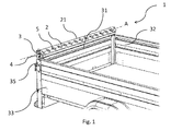
- Fig. 1 shows a perspective view of a load support structure 1.
- the load support structure 1 which may be arranged onto loading vehicle such as a trailer, a pickup truck or the like, comprises a load bearing member 2 which is rotationally coupled to a corner post adapter 4 on each end.
- the load bearing member has a longitudinal axis A and is rotationally coupled via a mounting element 3 such that it is rotatable around the longitudinal axis A.
- the mounting element 3 may be configured to provide the rotational adjustment such as a rivet and/or bushing or the like, which may be placed between the corner post adapter 4 and the load bearing member 2.
- the load bearing member 2 comprises load securing means 5 which facilitate the load to be securely fixated by using straps, ropes, wire or the like to prevent the load from sliding and hence risk to be damaged.
- the corner post adapter in fig. 1 is a vertical bar, adapted to fit into the square hollow of the trailer.
- the corner post adapters 4 are configured to be inserted with a suitable depth into a corner post 34 (see fig. 2 and 3 ), so that there is no risk for the corner post adapter 4 to dismount spontaneously.
- the load bearing member 2 may be coupled to a mounting element 3 which is directly coupled to a loading vehicle 30, without the need of a corner post adapter 4.
- the mounting element 3 comprises a pin, rivet, a bolt or the like that may allow the load bearing member 2 to rotate freely in order to adjust the position with regard to the angle of the load.
- a corner post adapter 4 inserted in a hollow corner post 34 of the trailer.
- the corner post adapter is fixated with a fastener, which in fig.4 is represented by a wing nut, for securing the corner post adapter in its place.
- a fastener which in fig.4 is represented by a wing nut, for securing the corner post adapter in its place.
- An alternative to a wing nut may be a click-arrangement, or a twist-arrangement, a regular bult head or the like. It is also alternatively possible to have a permanent mounting of the corner post adapter and the load bearing member 2 being detachable from the corner post adapter 4.
- Fig. 3 shows a detailed view of the load support structure comprising the mounting element, from a slightly different angle than fig. 2 .
- the rotational adjustment of the load bearing member 2 in one embodiment is enabled by a bushing and a rivet for free rotational adjustment.
- the load bearing member 2 is equipped with a hole on a distal end which is facing a corner post adapter in which the bushing is inserted.
- the vertical corner post adapter comprises a corresponding hole and the same level and a rivet is inserted through both holes for suspension of the load bearing member and the rivet and the bushing in combination provides a soft rotational movement.
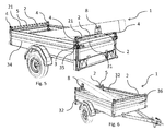
- Fig. 4 shows a load support structure 1 arranged on a trailer 30.
- the load support structure 1 in fig. 4 comprises two load bearing members 2 being arranged along the front and rear end of the trailer 30, respectively. That is on the front panel 36 and the rear panel 31, respectively. It is shown how a long load may be arranged along the entire length of the trailer 30, being securely strapped on each load bearing member in the securing loops on each load bearing member. It is shown that the load bearing member 2 has assumed an angle such that the load is resting on top of the load support surface 21 so that a big enough surface is in contact with the load to distribute the load over a larger area in order to prevent high stress concentrations locally on the load.
- a pair of load securing means 8 are arranged in order to fixate the load horizontally.
- the load support structure further comprises a pair of load retaining elements 8, each arranged on either side of the load in order to prevent the load from sliding horizontally along the load bearing member 2.
- the location of the load retaining element 8 is adjustable in order to suit the width of the current load.
- the load retaining element in fig. 5 have a vertical side, which is arranged inwards towards the load, and an angled side arranged oppositely to the vertical side. The angle is such that the load retaining element 8 has a wider base arranged against the load support surface 21.
- the load retaining element 8 may typically be arranged in the securing means (not shown).
- the attachment may be provided by inserting a protrusion of the load retaining element 8 in one or more of the load securing means 5.
- the attachment may also be provided by having a special attachment pin configured to fit the load securing means 5 on one end and the load retaining element 8 on the other end.
- Fig. 6 shows the load support structure 2 as shown in fig. 5 from a different angle.
- a load support structure 1 comprising two load bearing members 2, each arranged on a respective front 36 and rear panel 31 of the trailer 30.
- the first and second longitudinal rails 6, 7 comprise load securing means 5 for securing load in the trailer volume.
- the divider adapters 11 in fig.
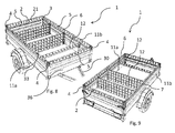
- divider element 10 are arranged to be suspended from a top portion of the first and second longitudinal rail 6, 7 and are arranged to provide means to attach one or more divider element 10 in the trailer load volume for dividing the space into several smaller compartments, as seen in fig. 8 and fig. 9 .
- the first and second longitudinal rails 6, 7 in fig. 7 may be fixedly arranged to the corner posts adapter 4.
- the longitudinal rails may comprise a similar rotationally adjustable mounting element as provided to the load bearing member 2.
Landscapes
- Engineering & Computer Science (AREA)
- Transportation (AREA)
- Mechanical Engineering (AREA)
- Health & Medical Sciences (AREA)
- Public Health (AREA)
- Body Structure For Vehicles (AREA)
Abstract
Description
- The present disclosure relates to a loading structure for a loading vehicle such as a pickup or trailer.
- Loading vehicles are often used to transport bulky or long goods. In some cases the long goods exceeds the length of the loading area of the loading vehicle, such as the trailer, and therefore the goods usually must be placed at an angle, with one end resting on the floor and one end resting on the top side of a side wall, commonly on a rear panel of the trailer. In order to securely fasten long loads the load is usually strapped against the rear panel. A problem with this solution is that it is not possible to open the rear panel as the goods are strapped against it. A solution to this problem may be to install a load support, see for example
US2002/0009347 A1 , which may comprise a horizontal support bar that may be fixed onto the loading vehicle, which the load may be secured against, and thereby the rear panel may be opened if needed. - However, when securing the load against a support bar, the tight strapping may cause the load to be damaged or dented. Therefore, there is a need for a more enhanced product to provide secure loading onto a trailer and decreasing the risk of damaging the goods.
- It is an object of the present invention to provide an improved solution that alleviates the mentioned drawbacks with present devices. Furthermore, it is an object to provide a load support structure for a loading vehicle comprising at least one load bearing member having a flat load support surface extending along a length of the load bearing member. Further, the load support structure comprises at least one mounting element for coupling the load bearing member to the loading vehicle in substantially horizontal orientation. The load bearing member is configured to be rotationally coupled relative the loading vehicle by means of the mounting element, so that the load bearing member is rotationally adjustable around its longitudinal axis.
- By definition, a loading vehicle as described may be a transport trailer, a pickup, a lorry, or any similar vehicle suitable for carrying a load.
- By allowing the load bearing member to be rotationally coupled to the vehicle via a mounting element, the rotational movement may easily be adjusted to adapt to the required angle to support a load when arranged against the flat load support surface. This rotational adjustment is an advantage since long loads, such as long pipes or planks, are typically arranged on the loading vehicle such as a trailer with one end resting against the trailer floor, and one end towards the load bearing member at an angle relative the floor. By having a load bearing member that is angularly adjustable, a flat surface portion of the load bearing member, which is the load support surface of the load bearing member may always be in contact with the load. By allowing a larger portion of the load to be in contact with the surface, the contact area is distributed over a larger surface and may therefore prevent high stress concentrations in the point of contact between the load and the load bearing member, which subsequently may prevent damages, dents or even breakage to the load, as well as it provides improved stability.
- By coupling the load bearing member to the trailer with mounting elements, the mounting elements may be configured to provide a rotationally adjustable mechanism, which allows the load bearing member to rotate relative to the trailer. The rotation may be achieved in various ways. For instance, the mounting element may provide rotation relative to the vehicle by being fixedly arranged to the vehicle and rotatable relative to the load bearing member, alternatively the mounting element may be fixedly arranged to the load bearing member and rotatable relative to the vehicle. Another alternative may be that the mounting element may be rotational relative to both vehicle and the load bearing bar. The mounting element may be any type of solution that may provide a rotational adjustment, such as a bushing, a ball bearing arrangement, a hinge, a rivet or the like.
- According to one embodiment of the invention, the rotation occurs freely with indefinite angular variation.
- This may be an advantage since a stepless adjustment may provide a more precise angular setting of the load bearing member for the current load which reduces the risk of damage to the load by ensuring that the whole flat loading surface abuts the load.
- According to yet another embodiment of the invention, the rotational adjustment may involve stepped adjustments such as a solution that clicks into a certain angle in angular steps. Further, any type of solution that may provide a rotation in order to adjust the angle of the load bearing member may be possible. It may also be possible to lock the load bearing member at the desired angle which may be an advantage if the trailer carries the same rigid load from time to time.
- According to another embodiment of the invention, the load support structure is configured such that when a load is arranged against the flat load support surface, the load bearing member may assume an angle substantially the same as the angle in which the load is arranged against the load bearing member relative the loading vehicle.
- By doing this, there may be no need for manual adjustment. The load bearing member may automatically swing into a suitable position. Further, less rigid load, such as thinner plastic pipes or thinner wooden planks, may bounce during transportation and hence the load bearing member may adjust its according to the current load angle. The load bearing member may alternatively be arranged to rotate with means of a crank, rope, cog wheel or the like for a controlled rotation.
- In one embodiment the load bearing member may have a cross section substantially rectangular in shape. However, the load bearing member may not be shaped as a closed rectangle, but may for instance be made from bent sheet steel with one or more sides open. However, the load bearing member may have a substantially flat load bearing surface.
- According to yet another embodiment, the load bearing member may be detachably arranged to the loading vehicle.
- By allowing detachable arrangement, the load support structure may be used only when needed. A load bearing member may, when arranged onto the trailer, be arranged across a rear wall of the trailer which generally may be openable. Since it may be desirable to be able to open the rear wall on a trailer, it may be an advantage that the load bearing member can be detachable and/or movable so that the load bearing member may not obstruct the opening. The load bearing member may be attachable to the trailer any way suitable for the specific installation. It may be by hooks, straps, clips, clamps or the like. It may also be by detachable screws, pins, rivets or the like.
- According to yet another embodiment, the load bearing member may be configured to be coupled to a corner post adapter. The corner post adapter may be configured to be arranged to the loading vehicle.
- The corner post adapter may be used in order to provide a detachable arrangement which easily can be removed from the vehicle. The corner post adapter may be a vertical member configured to be inserted in a hollow corner post. There may be a second corner post adapter arranged on the opposite corner post, and the load bearing member arranged between the two corner post adapters. The corner post adapter may be configured such that the load bearing member may be arranged on an upper part of the corner post adapter so that when inserted into the corner post, the load bearing member may be arranged above the corner post and along a rear panel to the opposite corner post, wherein the second corner post adapter may be arranged. The load support structure may be provided with a corner post adapter in each corner.
- According to yet another embodiment the load bearing member further may comprise load securing means.
- By providing the load bearing member with load securing means, it may facilitate strapping of a load against the load bearing member. The load bearing member may be provided with one or more load securing means, and the load securing means may be evenly distributed along at least a part of the length of the load bearing member.
- According to yet another embodiment the load securing means may be at least one of the following: apertures, loops, hooks or the like.
- By providing the load bearing member with load securing means of this type, it may facilitate secure strapping of the load. By having apertures, loops, hooks or the like distributed along the load bearing member, the strapping arrangements may be easily adapted for the size of the current load.
- According to yet another embodiment the load support structure further may comprise load retaining elements, configured to be detachably arranged on the load bearing member for preventing horizontal movement of the load.
- Thereby, the load may be retained on the load support structure. E.g. the retaining elements may prevent that the load can slide relative the load bearing member. The load retaining elements may be rigid supports. By being rigid, the load retaining members may be strong enough to retain bulky long load. The load retaining elements may be of such size that when they are coupled to the load bearing member, they may extend away from the load bearing member such that it may comfortably retain a sizable load, such as ventilation tube, ladders or the like. The support structure may be equipped with one, two or several load retaining members. The load retaining members may be used to divide the load into sections depending on the load size or shape in order to prevent different load to damage one another. For instance in one section there may be a stack of 50 mm tube, in another section there may be a ladder and so forth. The load retaining elements may be provided with load securing means in order to secure the load so as to reduce the risk for the load to bounce over the edge of the load retaining element.
- According to yet another embodiment, the load support structure may further comprise a first longitudinal rail to be arranged on a longitudinal side wall of the loading vehicle.
- By arranging a first longitudinal rail onto the loading vehicle, it may be possible to easily arrange load along the longitudinal sides. For instance, a bulk load such as a tall box may be placed onto the trailer floor. In order to fixate the box on the trailer, in order to prevent the box from sliding, the box may be strapped against the first longitudinal rail. The first longitudinal rail may be provided with load securing means to facilitate securing the load.
- According to yet another embodiment, the first longitudinal rail may be arranged to a corner post adapter.
- By allowing the first longitudinal rail to be coupled to the corner post adapter, the first longitudinal rail may be detachable along with the corner post adapter. The first longitudinal rail may be rotationally adjustable. The first longitudinal rail may alternatively be static. According to yet another embodiment, the load support structure may further comprise a second longitudinal rail configured to be arranged on the second longitudinal side wall located on the opposite side of the loading vehicle.
- By providing the load support structure with a second longitudinal rail, it may be possible to secure a large amount of load onto the trailer. Also, it may be possible to make attachments to both side panels at once, for instance when there is a need for multiple attachment points.
- According to yet another embodiment the load support structure may further comprise at least one divider element, configured to be detachably arranged to the first and second longitudinal rail.
- By having a divider element, it may be possible to divide the loading volume of the loading vehicle into smaller sections. This may be an advantage since smaller sections may prevent loose load to slip. Also, it may be possible to sort load into the different sections. The divider element may be a thin piece of rail, substantially the same material as the other rails in the load support structure. There may also be a number of divider elements arranged on different locations. The divider element may alternatively be a larger piece of material, such that each divider element reaches from the trailer floor to a top edge of the trailer side walls. Another alternative may be that a number of thinner divider elements may be stacked in top of each other in order to provide a suitable height. The divider element may comprise load securing means.
- According to yet another embodiment, the load support structure may further comprise at least a first and a second divider adapter, wherein the first divider adapter may be configured to be arranged on said first longitudinal rail and the second divider adapter may be configured to be arranged on the second longitudinal rail. The divider element may be configured to be arranged to the first and second divider adapter.
- By providing a divider adapter, it may be possible to easily arrange a number of divider elements to the loading vehicle without the need for fixating divider elements directly to the vehicle. Due to this, there is no need to use permanent joining methods or to use fasteners or drill permanent holes. The divider adapters may be configured such that they may hang onto the first and second longitudinal rail. Alternatively, they may be configured to be coupled to the load securing means. This may be done by fasteners, clips, clamps straps or the like.
- In another aspect of the inventive concept, the objectives mentioned above are achieved by a loading vehicle comprising a load support structure, according to any of the preceding embodiments. Thereby, the advantages described above may be achieved on a loading vehicle.
- In another aspect of the inventive concept, the objectives mentioned above are achieved by use of a load support structure for receiving a load on a loading vehicle, wherein the support structure comprises at least one load bearing member having a flat load support surface extending along a length of the load bearing member. Moreover, the support structure comprises at least one mounting element coupling said load bearing member to said loading vehicle in a substantially horizontal orientation, and wherein the load bearing member is rotationally coupled relative said loading vehicle by means of said mounting element, so that said load bearing member is rotationally adjustable around its longitudinal axis, and wherein said flat load support surface is used to support said load during transportation, so as to distribute pressure from the load resting on said flat load support surface over the whole flat load support surface. Thereby, the advantages described above may be achieved by using a load support structure for receiving a load on a loading vehicle.
- Further features of, and advantages with, the present invention will become apparent when studying the appended claims and the following description. The skilled addressee realize that different features of the present invention may be combined to create embodiments other than those described in the following, without departing from the scope of the present invention.
- The invention will in the following be described in more detail with reference to the enclosed drawings, wherein:
-
Fig. 1 shows a perspective view of a support structure according to an embodiment of the invention. -
Fig. 2 shows a detailed view of a support structure according to an embodiment of the invention. -
Fig. 3 shows a detailed view of a support structure according to an embodiment of the invention. -
Fig. 4 shows a perspective view of a support structure according to an embodiment of the invention. -
Fig. 5 shows a perspective view of a support structure according to an embodiment of the invention. -
Fig. 6 shows a perspective view of a support structure according to an embodiment of the invention. -
Fig. 7 shows an exploded view of a support structure according to an embodiment of the invention. -
Fig. 8 shows a perspective view of a support structure according to an embodiment of the invention. -
Fig. 9 shows a perspective view of a support structure according to an embodiment of the invention. - The present invention will be described more fully hereinafter with reference to the accompanying drawings, in which preferred embodiments of the invention are shown. This invention may, however, be embodied in many different forms and should not be construed as limited to the embodiments set forth herein; rather, these embodiments are provided so that this disclosure will be thorough and complete, and will fully convey the scope of the invention to those skilled in the art. In the drawings, like numbers refer to like elements.
-
Fig. 1 shows a perspective view of aload support structure 1. Theload support structure 1, which may be arranged onto loading vehicle such as a trailer, a pickup truck or the like, comprises aload bearing member 2 which is rotationally coupled to acorner post adapter 4 on each end. The load bearing member has a longitudinal axis A and is rotationally coupled via a mountingelement 3 such that it is rotatable around the longitudinal axis A. The mountingelement 3 may be configured to provide the rotational adjustment such as a rivet and/or bushing or the like, which may be placed between thecorner post adapter 4 and theload bearing member 2. As illustrated, theload bearing member 2 comprises load securing means 5 which facilitate the load to be securely fixated by using straps, ropes, wire or the like to prevent the load from sliding and hence risk to be damaged. The corner post adapter infig. 1 is a vertical bar, adapted to fit into the square hollow of the trailer. Thecorner post adapters 4 are configured to be inserted with a suitable depth into a corner post 34 (seefig. 2 and 3 ), so that there is no risk for thecorner post adapter 4 to dismount spontaneously. Alternatively, theload bearing member 2 may be coupled to a mountingelement 3 which is directly coupled to aloading vehicle 30, without the need of acorner post adapter 4. Infig. 1 , the mountingelement 3 comprises a pin, rivet, a bolt or the like that may allow theload bearing member 2 to rotate freely in order to adjust the position with regard to the angle of the load. - Further in
fig. 2 it is shown acorner post adapter 4 inserted in a hollow corner post 34 of the trailer. The corner post adapter is fixated with a fastener, which infig.4 is represented by a wing nut, for securing the corner post adapter in its place. By choosing a wing nut, it may be possible to easily detach the support structure from the trailer by hand, without any special tools, when it is not in use by lifting thecorner post adapter 4 out of thecorner post 34. An alternative to a wing nut may be a click-arrangement, or a twist-arrangement, a regular bult head or the like. It is also alternatively possible to have a permanent mounting of the corner post adapter and theload bearing member 2 being detachable from thecorner post adapter 4. -
Fig. 3 shows a detailed view of the load support structure comprising the mounting element, from a slightly different angle thanfig. 2 . Infig. 3 it is shown that the rotational adjustment of theload bearing member 2 in one embodiment is enabled by a bushing and a rivet for free rotational adjustment. Theload bearing member 2 is equipped with a hole on a distal end which is facing a corner post adapter in which the bushing is inserted. The vertical corner post adapter comprises a corresponding hole and the same level and a rivet is inserted through both holes for suspension of the load bearing member and the rivet and the bushing in combination provides a soft rotational movement. -
Fig. 4 shows aload support structure 1 arranged on atrailer 30. Theload support structure 1 infig. 4 comprises twoload bearing members 2 being arranged along the front and rear end of thetrailer 30, respectively. That is on thefront panel 36 and therear panel 31, respectively. It is shown how a long load may be arranged along the entire length of thetrailer 30, being securely strapped on each load bearing member in the securing loops on each load bearing member. It is shown that theload bearing member 2 has assumed an angle such that the load is resting on top of theload support surface 21 so that a big enough surface is in contact with the load to distribute the load over a larger area in order to prevent high stress concentrations locally on the load. At theload bearing member 2 located on thefront panel 36, a pair of load securing means 8 are arranged in order to fixate the load horizontally. - In
fig. 5 it is shown a long load being angularly arranged against theload support structure 1 with one end resting against the trailer floor, and one end resting against the horizontalload support surface 21. The load support structure further comprises a pair ofload retaining elements 8, each arranged on either side of the load in order to prevent the load from sliding horizontally along theload bearing member 2. The location of theload retaining element 8 is adjustable in order to suit the width of the current load. The load retaining element infig. 5 have a vertical side, which is arranged inwards towards the load, and an angled side arranged oppositely to the vertical side. The angle is such that theload retaining element 8 has a wider base arranged against theload support surface 21. Theload retaining element 8 may typically be arranged in the securing means (not shown). The attachment may be provided by inserting a protrusion of theload retaining element 8 in one or more of the load securing means 5. The attachment may also be provided by having a special attachment pin configured to fit the load securing means 5 on one end and theload retaining element 8 on the other end. -
Fig. 6 shows theload support structure 2 as shown infig. 5 from a different angle. - In
fig. 7 , there is an exploded view of aload support structure 1 comprising twoload bearing members 2, each arranged on arespective front 36 andrear panel 31 of thetrailer 30. There are further a first 6 and a secondlongitudinal rail 7, each arranged on a first 32 andsecond side 33 of the trailer. The first and secondlongitudinal rails corner post adapter 4 arranged in each corner post 34 of thetrailer 30 which provides attachment for the first and secondlongitudinal rails load bearing members 2. Further it is shown a pair of divider adapters 11, each arranged on one respective first and secondlongitudinal rail fig. 7 are arranged to be suspended from a top portion of the first and secondlongitudinal rail fig. 8 and fig. 9 . - The first and second
longitudinal rails fig. 7 may be fixedly arranged to the corner postsadapter 4. Alternatively the longitudinal rails may comprise a similar rotationally adjustable mounting element as provided to theload bearing member 2. By arranging the rails to cornerpost adapters 4, the wholeload support structure 1 may be detachable. - While the present invention has been described with reference to a number of preferred embodiments, it will be understood by those skilled in the art that various changes may be made and equivalents may be substituted for elements thereof without departing from the scope of the invention. In addition, many modifications may be made to adapt a particular situation or material to the teachings of the invention without departing from the essential scope thereof. Therefore, it is intended that the invention not be limited to the particular embodiments disclosed as the best mode contemplated for carrying out this invention, but that the invention will include all embodiments falling within the scope of the appended claims. Moreover, the use of the terms first, second, etc. do not denote any order or importance, but rather the terms first, second, etc. are used to distinguish one element from another.
- In the drawings and specification, there have been disclosed preferred embodiments and examples of the invention and, although specific terms are employed, they are used in a generic and descriptive sense only and not for the purpose of limitation, the scope of the invention being set forth in the following claims.
Claims (15)
- A load support structure (1) for a loading vehicle (30) comprising- at least one load bearing member (2) having a flat load support surface (21) extending along a length of the load bearing member (2),- at least one mounting element (3) for coupling said load bearing member (2), to said loading vehicle in substantially horizontal orientation,characterized in that
said load bearing member (2) is configured to be rotationally coupled relative said loading vehicle (30) by means of said mounting element (3), so that said load bearing member (2) is rotationally adjustable around its longitudinal axis (A). - Load support structure (1) according to claim 1, wherein the rotation occurs freely with indefinite angular variation.
- Load support structure (1) according to claim 1 or 2, wherein the load support structure is configured such that when a load is arranged against said flat load support surface (21), said load bearing member (2) assumes an angle substantially the same as the angle in which the load is arranged against the load bearing member relative the loading vehicle.
- Load support structure (1) according to any of claims 1-3, wherein the load bearing member (2) is detachably arranged to the loading vehicle.
- Load support structure according to any of claims 1-4, wherein the load bearing member (2) is configured to be coupled to a corner post adapter (4), wherein the corner post adapter (4) is configured to be arranged to the loading vehicle.
- Load support structure (1) according to any of the preceding claims, wherein the load support surface (21) further comprises load securing means (5).
- Load support structure (1) according to claim 6, wherein the load securing means is at least one of the following: apertures, loops or hooks.
- Load support structure (1) according to any of the preceding claims further comprising load retaining elements (8), configured to be detachably arranged on said load bearing member (8) for preventing horizontal movement of the load.
- Load support structure (1) according to any of the preceding claims, further comprising a first longitudinal rail (6) to be arranged on a longitudinal side wall (9) of the loading vehicle.
- Load support structure (1) according to claim 9, wherein the first longitudinal rail (6) is arranged to a corner post adapter (4).
- Load support structure (1) according to claim 8 or 9, further comprising a second longitudinal rail (7) configured to be arranged on a second longitudinal side wall (9) located on the opposite side of the loading vehicle.
- Load support structure (1) according to claim 11 further comprising at least one divider element (10), configured to be detachably arranged to said first and second longitudinal rail (6, 7).
- Load support structure (1) according to claim 10, further comprising at least a first and a second divider adapter (11 a, 11 b), wherein the first divider adapter (11 a) is configured to be arranged on said first longitudinal rail (6) and the second divider adapter (11 b) is configured to be arranged on the second longitudinal rail (7), wherein said divider element (9) is configured to be arranged to said first and second divider adapter (11a, 11b).
- Loading vehicle (30) comprising a load support structure (1), according to any of the preceding claims.
- Use of a load support structure (1) for receiving a load on a loading vehicle (30), said support structure comprising- at least one load bearing member (2) having a flat load support surface (21) extending along a length of the load bearing member (2),- at least one mounting element (3) coupling said load bearing member (2) to said loading vehicle in a substantially horizontal orientation,characterized in that
said load bearing member (2) is rotationally coupled relative said loading vehicle (30) by means of said mounting element (3), so that said load bearing member (2) is rotationally adjustable around its longitudinal axis (A), and said flat load support surface is used to support said load during transportation, so as to distribute pressure from the load resting on said flat load support surface (21) over the whole flat load support surface (21).
Priority Applications (3)
| Application Number | Priority Date | Filing Date | Title |
|---|---|---|---|
| EP14198617.4A EP3034356B1 (en) | 2014-12-17 | 2014-12-17 | Load support structure for a loading vehicle |
| DK14198617.4T DK3034356T3 (en) | 2014-12-17 | 2014-12-17 | Load support structure for a truck |
| NO14198617A NO3034356T3 (en) | 2014-12-17 | 2014-12-17 |
Applications Claiming Priority (1)
| Application Number | Priority Date | Filing Date | Title |
|---|---|---|---|
| EP14198617.4A EP3034356B1 (en) | 2014-12-17 | 2014-12-17 | Load support structure for a loading vehicle |
Publications (2)
| Publication Number | Publication Date |
|---|---|
| EP3034356A1 true EP3034356A1 (en) | 2016-06-22 |
| EP3034356B1 EP3034356B1 (en) | 2018-03-21 |
Family
ID=52146190
Family Applications (1)
| Application Number | Title | Priority Date | Filing Date |
|---|---|---|---|
| EP14198617.4A Not-in-force EP3034356B1 (en) | 2014-12-17 | 2014-12-17 | Load support structure for a loading vehicle |
Country Status (3)
| Country | Link |
|---|---|
| EP (1) | EP3034356B1 (en) |
| DK (1) | DK3034356T3 (en) |
| NO (1) | NO3034356T3 (en) |
Citations (4)
| Publication number | Priority date | Publication date | Assignee | Title |
|---|---|---|---|---|
| US5800145A (en) * | 1997-05-16 | 1998-09-01 | Kelce; Donald Lee | Cargo restraining device |
| US20020009347A1 (en) | 2000-07-21 | 2002-01-24 | John Stafford | Crate gate |
| WO2002087920A1 (en) * | 2001-04-19 | 2002-11-07 | Loading Zone Llc | Height adjustment system for truck bed divider |
| US6988756B1 (en) * | 2004-11-16 | 2006-01-24 | Meinke Joseph S | Modular extender tailgate |
Family Cites Families (3)
| Publication number | Priority date | Publication date | Assignee | Title |
|---|---|---|---|---|
| US2332991A (en) * | 1941-10-17 | 1943-10-26 | Henry L Commire | Self-adjustable cradle for boat trailers |
| US3122245A (en) * | 1961-01-03 | 1964-02-25 | Firestone Tire & Rubber Co | Boat trailer |
| US3856168A (en) * | 1973-05-03 | 1974-12-24 | Buta J | Boat trailer construction |
-
2014
- 2014-12-17 EP EP14198617.4A patent/EP3034356B1/en not_active Not-in-force
- 2014-12-17 DK DK14198617.4T patent/DK3034356T3/en active
- 2014-12-17 NO NO14198617A patent/NO3034356T3/no unknown
Patent Citations (4)
| Publication number | Priority date | Publication date | Assignee | Title |
|---|---|---|---|---|
| US5800145A (en) * | 1997-05-16 | 1998-09-01 | Kelce; Donald Lee | Cargo restraining device |
| US20020009347A1 (en) | 2000-07-21 | 2002-01-24 | John Stafford | Crate gate |
| WO2002087920A1 (en) * | 2001-04-19 | 2002-11-07 | Loading Zone Llc | Height adjustment system for truck bed divider |
| US6988756B1 (en) * | 2004-11-16 | 2006-01-24 | Meinke Joseph S | Modular extender tailgate |
Also Published As
| Publication number | Publication date |
|---|---|
| NO3034356T3 (en) | 2018-08-18 |
| EP3034356B1 (en) | 2018-03-21 |
| DK3034356T3 (en) | 2018-05-28 |
Similar Documents
| Publication | Publication Date | Title |
|---|---|---|
| US5816637A (en) | Truck cargo space extension bed | |
| US8182012B1 (en) | Tailgate extension apparatus | |
| US7296836B1 (en) | Truck rack apparatus | |
| US20110027034A1 (en) | Cargo control system adaptor | |
| US8261880B1 (en) | Step ladder apparatus | |
| US9713978B2 (en) | Vertically adjustable and removable headache rack system | |
| US8366373B2 (en) | Collapsible, lightweight mount to support a cargo loading device | |
| MXPA00007528A (en) | Shelving accessory mounting system for a cabinet assembly. | |
| US9915096B2 (en) | Garage door ladder storage devices and methods thereof | |
| US7740430B2 (en) | Support assembly for use with truck bed | |
| US11787347B1 (en) | Universal, no drill ladder rack | |
| US20160237702A1 (en) | Adjustable Scaffolding | |
| US20180105119A1 (en) | Hitch mount angle adjustable transport rack to carry an elongated item | |
| US20130136556A1 (en) | Rack For Load Bars | |
| US7849963B1 (en) | Ladder carrier apparatus | |
| US20160251892A1 (en) | Horizontal Reinforcement Bar | |
| US9259080B1 (en) | Apparatus for a handrail system having railings | |
| US8104577B1 (en) | Ladder stabilizer for flatbed truck | |
| JP2006515258A (en) | Elevator door height adjustment clip | |
| US11835254B1 (en) | Window Unit Air Conditioner installer and support rod | |
| EP3034356B1 (en) | Load support structure for a loading vehicle | |
| US20230192199A1 (en) | Railing assembly for trailer | |
| US12319359B1 (en) | Pivotable and nestable cargo rack for truck bed or trailer | |
| US20110073729A1 (en) | Ladder storage device | |
| US20110012385A1 (en) | Modular tailgate protectors and load support systems |
Legal Events
| Date | Code | Title | Description |
|---|---|---|---|
| PUAI | Public reference made under article 153(3) epc to a published international application that has entered the european phase |
Free format text: ORIGINAL CODE: 0009012 |
|
| AK | Designated contracting states |
Kind code of ref document: A1 Designated state(s): AL AT BE BG CH CY CZ DE DK EE ES FI FR GB GR HR HU IE IS IT LI LT LU LV MC MK MT NL NO PL PT RO RS SE SI SK SM TR |
|
| AX | Request for extension of the european patent |
Extension state: BA ME |
|
| 17P | Request for examination filed |
Effective date: 20161221 |
|
| RBV | Designated contracting states (corrected) |
Designated state(s): AL AT BE BG CH CY CZ DE DK EE ES FI FR GB GR HR HU IE IS IT LI LT LU LV MC MK MT NL NO PL PT RO RS SE SI SK SM TR |
|
| GRAP | Despatch of communication of intention to grant a patent |
Free format text: ORIGINAL CODE: EPIDOSNIGR1 |
|
| INTG | Intention to grant announced |
Effective date: 20171013 |
|
| GRAS | Grant fee paid |
Free format text: ORIGINAL CODE: EPIDOSNIGR3 |
|
| GRAA | (expected) grant |
Free format text: ORIGINAL CODE: 0009210 |
|
| AK | Designated contracting states |
Kind code of ref document: B1 Designated state(s): AL AT BE BG CH CY CZ DE DK EE ES FI FR GB GR HR HU IE IS IT LI LT LU LV MC MK MT NL NO PL PT RO RS SE SI SK SM TR |
|
| REG | Reference to a national code |
Ref country code: GB Ref legal event code: FG4D |
|
| REG | Reference to a national code |
Ref country code: CH Ref legal event code: EP |
|
| REG | Reference to a national code |
Ref country code: AT Ref legal event code: REF Ref document number: 980721 Country of ref document: AT Kind code of ref document: T Effective date: 20180415 |
|
| REG | Reference to a national code |
Ref country code: IE Ref legal event code: FG4D |
|
| REG | Reference to a national code |
Ref country code: DE Ref legal event code: R096 Ref document number: 602014022557 Country of ref document: DE |
|
| REG | Reference to a national code |
Ref country code: SE Ref legal event code: TRGR |
|
| REG | Reference to a national code |
Ref country code: DK Ref legal event code: T3 Effective date: 20180522 |
|
| REG | Reference to a national code |
Ref country code: NO Ref legal event code: T2 Effective date: 20180321 |
|
| REG | Reference to a national code |
Ref country code: NL Ref legal event code: MP Effective date: 20180321 |
|
| PG25 | Lapsed in a contracting state [announced via postgrant information from national office to epo] |
Ref country code: LT Free format text: LAPSE BECAUSE OF FAILURE TO SUBMIT A TRANSLATION OF THE DESCRIPTION OR TO PAY THE FEE WITHIN THE PRESCRIBED TIME-LIMIT Effective date: 20180321 Ref country code: HR Free format text: LAPSE BECAUSE OF FAILURE TO SUBMIT A TRANSLATION OF THE DESCRIPTION OR TO PAY THE FEE WITHIN THE PRESCRIBED TIME-LIMIT Effective date: 20180321 Ref country code: FI Free format text: LAPSE BECAUSE OF FAILURE TO SUBMIT A TRANSLATION OF THE DESCRIPTION OR TO PAY THE FEE WITHIN THE PRESCRIBED TIME-LIMIT Effective date: 20180321 Ref country code: CY Free format text: LAPSE BECAUSE OF FAILURE TO SUBMIT A TRANSLATION OF THE DESCRIPTION OR TO PAY THE FEE WITHIN THE PRESCRIBED TIME-LIMIT Effective date: 20180321 |
|
| REG | Reference to a national code |
Ref country code: LT Ref legal event code: MG4D |
|
| REG | Reference to a national code |
Ref country code: AT Ref legal event code: MK05 Ref document number: 980721 Country of ref document: AT Kind code of ref document: T Effective date: 20180321 |
|
| PG25 | Lapsed in a contracting state [announced via postgrant information from national office to epo] |
Ref country code: LV Free format text: LAPSE BECAUSE OF FAILURE TO SUBMIT A TRANSLATION OF THE DESCRIPTION OR TO PAY THE FEE WITHIN THE PRESCRIBED TIME-LIMIT Effective date: 20180321 Ref country code: GR Free format text: LAPSE BECAUSE OF FAILURE TO SUBMIT A TRANSLATION OF THE DESCRIPTION OR TO PAY THE FEE WITHIN THE PRESCRIBED TIME-LIMIT Effective date: 20180622 Ref country code: BG Free format text: LAPSE BECAUSE OF FAILURE TO SUBMIT A TRANSLATION OF THE DESCRIPTION OR TO PAY THE FEE WITHIN THE PRESCRIBED TIME-LIMIT Effective date: 20180621 Ref country code: RS Free format text: LAPSE BECAUSE OF FAILURE TO SUBMIT A TRANSLATION OF THE DESCRIPTION OR TO PAY THE FEE WITHIN THE PRESCRIBED TIME-LIMIT Effective date: 20180321 |
|
| PG25 | Lapsed in a contracting state [announced via postgrant information from national office to epo] |
Ref country code: IT Free format text: LAPSE BECAUSE OF FAILURE TO SUBMIT A TRANSLATION OF THE DESCRIPTION OR TO PAY THE FEE WITHIN THE PRESCRIBED TIME-LIMIT Effective date: 20180321 Ref country code: AL Free format text: LAPSE BECAUSE OF FAILURE TO SUBMIT A TRANSLATION OF THE DESCRIPTION OR TO PAY THE FEE WITHIN THE PRESCRIBED TIME-LIMIT Effective date: 20180321 Ref country code: PL Free format text: LAPSE BECAUSE OF FAILURE TO SUBMIT A TRANSLATION OF THE DESCRIPTION OR TO PAY THE FEE WITHIN THE PRESCRIBED TIME-LIMIT Effective date: 20180321 Ref country code: EE Free format text: LAPSE BECAUSE OF FAILURE TO SUBMIT A TRANSLATION OF THE DESCRIPTION OR TO PAY THE FEE WITHIN THE PRESCRIBED TIME-LIMIT Effective date: 20180321 Ref country code: RO Free format text: LAPSE BECAUSE OF FAILURE TO SUBMIT A TRANSLATION OF THE DESCRIPTION OR TO PAY THE FEE WITHIN THE PRESCRIBED TIME-LIMIT Effective date: 20180321 Ref country code: ES Free format text: LAPSE BECAUSE OF FAILURE TO SUBMIT A TRANSLATION OF THE DESCRIPTION OR TO PAY THE FEE WITHIN THE PRESCRIBED TIME-LIMIT Effective date: 20180321 Ref country code: NL Free format text: LAPSE BECAUSE OF FAILURE TO SUBMIT A TRANSLATION OF THE DESCRIPTION OR TO PAY THE FEE WITHIN THE PRESCRIBED TIME-LIMIT Effective date: 20180321 |
|
| PG25 | Lapsed in a contracting state [announced via postgrant information from national office to epo] |
Ref country code: SM Free format text: LAPSE BECAUSE OF FAILURE TO SUBMIT A TRANSLATION OF THE DESCRIPTION OR TO PAY THE FEE WITHIN THE PRESCRIBED TIME-LIMIT Effective date: 20180321 Ref country code: SK Free format text: LAPSE BECAUSE OF FAILURE TO SUBMIT A TRANSLATION OF THE DESCRIPTION OR TO PAY THE FEE WITHIN THE PRESCRIBED TIME-LIMIT Effective date: 20180321 Ref country code: CZ Free format text: LAPSE BECAUSE OF FAILURE TO SUBMIT A TRANSLATION OF THE DESCRIPTION OR TO PAY THE FEE WITHIN THE PRESCRIBED TIME-LIMIT Effective date: 20180321 Ref country code: AT Free format text: LAPSE BECAUSE OF FAILURE TO SUBMIT A TRANSLATION OF THE DESCRIPTION OR TO PAY THE FEE WITHIN THE PRESCRIBED TIME-LIMIT Effective date: 20180321 |
|
| PG25 | Lapsed in a contracting state [announced via postgrant information from national office to epo] |
Ref country code: PT Free format text: LAPSE BECAUSE OF FAILURE TO SUBMIT A TRANSLATION OF THE DESCRIPTION OR TO PAY THE FEE WITHIN THE PRESCRIBED TIME-LIMIT Effective date: 20180723 |
|
| REG | Reference to a national code |
Ref country code: DE Ref legal event code: R097 Ref document number: 602014022557 Country of ref document: DE |
|
| PLBE | No opposition filed within time limit |
Free format text: ORIGINAL CODE: 0009261 |
|
| STAA | Information on the status of an ep patent application or granted ep patent |
Free format text: STATUS: NO OPPOSITION FILED WITHIN TIME LIMIT |
|
| 26N | No opposition filed |
Effective date: 20190102 |
|
| PG25 | Lapsed in a contracting state [announced via postgrant information from national office to epo] |
Ref country code: SI Free format text: LAPSE BECAUSE OF FAILURE TO SUBMIT A TRANSLATION OF THE DESCRIPTION OR TO PAY THE FEE WITHIN THE PRESCRIBED TIME-LIMIT Effective date: 20180321 |
|
| REG | Reference to a national code |
Ref country code: CH Ref legal event code: PL |
|
| PG25 | Lapsed in a contracting state [announced via postgrant information from national office to epo] |
Ref country code: LU Free format text: LAPSE BECAUSE OF NON-PAYMENT OF DUE FEES Effective date: 20181217 Ref country code: MC Free format text: LAPSE BECAUSE OF FAILURE TO SUBMIT A TRANSLATION OF THE DESCRIPTION OR TO PAY THE FEE WITHIN THE PRESCRIBED TIME-LIMIT Effective date: 20180321 |
|
| REG | Reference to a national code |
Ref country code: IE Ref legal event code: MM4A |
|
| REG | Reference to a national code |
Ref country code: BE Ref legal event code: MM Effective date: 20181231 |
|
| PG25 | Lapsed in a contracting state [announced via postgrant information from national office to epo] |
Ref country code: IE Free format text: LAPSE BECAUSE OF NON-PAYMENT OF DUE FEES Effective date: 20181217 |
|
| PG25 | Lapsed in a contracting state [announced via postgrant information from national office to epo] |
Ref country code: BE Free format text: LAPSE BECAUSE OF NON-PAYMENT OF DUE FEES Effective date: 20181231 |
|
| PG25 | Lapsed in a contracting state [announced via postgrant information from national office to epo] |
Ref country code: CH Free format text: LAPSE BECAUSE OF NON-PAYMENT OF DUE FEES Effective date: 20181231 Ref country code: LI Free format text: LAPSE BECAUSE OF NON-PAYMENT OF DUE FEES Effective date: 20181231 |
|
| PG25 | Lapsed in a contracting state [announced via postgrant information from national office to epo] |
Ref country code: MT Free format text: LAPSE BECAUSE OF NON-PAYMENT OF DUE FEES Effective date: 20181217 |
|
| PGFP | Annual fee paid to national office [announced via postgrant information from national office to epo] |
Ref country code: NO Payment date: 20191118 Year of fee payment: 6 Ref country code: SE Payment date: 20191115 Year of fee payment: 6 Ref country code: DE Payment date: 20191119 Year of fee payment: 6 |
|
| PGFP | Annual fee paid to national office [announced via postgrant information from national office to epo] |
Ref country code: FR Payment date: 20191118 Year of fee payment: 6 Ref country code: DK Payment date: 20191119 Year of fee payment: 6 |
|
| PG25 | Lapsed in a contracting state [announced via postgrant information from national office to epo] |
Ref country code: TR Free format text: LAPSE BECAUSE OF FAILURE TO SUBMIT A TRANSLATION OF THE DESCRIPTION OR TO PAY THE FEE WITHIN THE PRESCRIBED TIME-LIMIT Effective date: 20180321 |
|
| PGFP | Annual fee paid to national office [announced via postgrant information from national office to epo] |
Ref country code: GB Payment date: 20191118 Year of fee payment: 6 |
|
| PG25 | Lapsed in a contracting state [announced via postgrant information from national office to epo] |
Ref country code: HU Free format text: LAPSE BECAUSE OF FAILURE TO SUBMIT A TRANSLATION OF THE DESCRIPTION OR TO PAY THE FEE WITHIN THE PRESCRIBED TIME-LIMIT; INVALID AB INITIO Effective date: 20141217 Ref country code: MK Free format text: LAPSE BECAUSE OF NON-PAYMENT OF DUE FEES Effective date: 20180321 |
|
| PG25 | Lapsed in a contracting state [announced via postgrant information from national office to epo] |
Ref country code: IS Free format text: LAPSE BECAUSE OF FAILURE TO SUBMIT A TRANSLATION OF THE DESCRIPTION OR TO PAY THE FEE WITHIN THE PRESCRIBED TIME-LIMIT Effective date: 20180721 |
|
| REG | Reference to a national code |
Ref country code: DE Ref legal event code: R119 Ref document number: 602014022557 Country of ref document: DE |
|
| REG | Reference to a national code |
Ref country code: DK Ref legal event code: EBP Effective date: 20201231 |
|
| REG | Reference to a national code |
Ref country code: NO Ref legal event code: MMEP |
|
| REG | Reference to a national code |
Ref country code: SE Ref legal event code: EUG |
|
| GBPC | Gb: european patent ceased through non-payment of renewal fee |
Effective date: 20201217 |
|
| PG25 | Lapsed in a contracting state [announced via postgrant information from national office to epo] |
Ref country code: FR Free format text: LAPSE BECAUSE OF NON-PAYMENT OF DUE FEES Effective date: 20201231 |
|
| PG25 | Lapsed in a contracting state [announced via postgrant information from national office to epo] |
Ref country code: SE Free format text: LAPSE BECAUSE OF NON-PAYMENT OF DUE FEES Effective date: 20201218 Ref country code: NO Free format text: LAPSE BECAUSE OF NON-PAYMENT OF DUE FEES Effective date: 20201231 Ref country code: DE Free format text: LAPSE BECAUSE OF NON-PAYMENT OF DUE FEES Effective date: 20210701 Ref country code: GB Free format text: LAPSE BECAUSE OF NON-PAYMENT OF DUE FEES Effective date: 20201217 |
|
| PG25 | Lapsed in a contracting state [announced via postgrant information from national office to epo] |
Ref country code: DK Free format text: LAPSE BECAUSE OF NON-PAYMENT OF DUE FEES Effective date: 20201231 |