EP3034268A1 - Apparatus for producing laminated fabric ply strips - Google Patents
Apparatus for producing laminated fabric ply strips Download PDFInfo
- Publication number
- EP3034268A1 EP3034268A1 EP15200484.2A EP15200484A EP3034268A1 EP 3034268 A1 EP3034268 A1 EP 3034268A1 EP 15200484 A EP15200484 A EP 15200484A EP 3034268 A1 EP3034268 A1 EP 3034268A1
- Authority
- EP
- European Patent Office
- Prior art keywords
- cross
- die
- die assembly
- assembly
- slot
- Prior art date
- Legal status (The legal status is an assumption and is not a legal conclusion. Google has not performed a legal analysis and makes no representation as to the accuracy of the status listed.)
- Withdrawn
Links
Images









Classifications
-
- B—PERFORMING OPERATIONS; TRANSPORTING
- B29—WORKING OF PLASTICS; WORKING OF SUBSTANCES IN A PLASTIC STATE IN GENERAL
- B29D—PRODUCING PARTICULAR ARTICLES FROM PLASTICS OR FROM SUBSTANCES IN A PLASTIC STATE
- B29D30/00—Producing pneumatic or solid tyres or parts thereof
- B29D30/06—Pneumatic tyres or parts thereof (e.g. produced by casting, moulding, compression moulding, injection moulding, centrifugal casting)
- B29D30/38—Textile inserts, e.g. cord or canvas layers, for tyres; Treatment of inserts prior to building the tyre
-
- B—PERFORMING OPERATIONS; TRANSPORTING
- B29—WORKING OF PLASTICS; WORKING OF SUBSTANCES IN A PLASTIC STATE IN GENERAL
- B29C—SHAPING OR JOINING OF PLASTICS; SHAPING OF MATERIAL IN A PLASTIC STATE, NOT OTHERWISE PROVIDED FOR; AFTER-TREATMENT OF THE SHAPED PRODUCTS, e.g. REPAIRING
- B29C48/00—Extrusion moulding, i.e. expressing the moulding material through a die or nozzle which imparts the desired form; Apparatus therefor
- B29C48/15—Extrusion moulding, i.e. expressing the moulding material through a die or nozzle which imparts the desired form; Apparatus therefor incorporating preformed parts or layers, e.g. extrusion moulding around inserts
- B29C48/156—Coating two or more articles simultaneously
-
- B—PERFORMING OPERATIONS; TRANSPORTING
- B29—WORKING OF PLASTICS; WORKING OF SUBSTANCES IN A PLASTIC STATE IN GENERAL
- B29C—SHAPING OR JOINING OF PLASTICS; SHAPING OF MATERIAL IN A PLASTIC STATE, NOT OTHERWISE PROVIDED FOR; AFTER-TREATMENT OF THE SHAPED PRODUCTS, e.g. REPAIRING
- B29C48/00—Extrusion moulding, i.e. expressing the moulding material through a die or nozzle which imparts the desired form; Apparatus therefor
- B29C48/03—Extrusion moulding, i.e. expressing the moulding material through a die or nozzle which imparts the desired form; Apparatus therefor characterised by the shape of the extruded material at extrusion
- B29C48/07—Flat, e.g. panels
-
- B—PERFORMING OPERATIONS; TRANSPORTING
- B29—WORKING OF PLASTICS; WORKING OF SUBSTANCES IN A PLASTIC STATE IN GENERAL
- B29C—SHAPING OR JOINING OF PLASTICS; SHAPING OF MATERIAL IN A PLASTIC STATE, NOT OTHERWISE PROVIDED FOR; AFTER-TREATMENT OF THE SHAPED PRODUCTS, e.g. REPAIRING
- B29C48/00—Extrusion moulding, i.e. expressing the moulding material through a die or nozzle which imparts the desired form; Apparatus therefor
- B29C48/03—Extrusion moulding, i.e. expressing the moulding material through a die or nozzle which imparts the desired form; Apparatus therefor characterised by the shape of the extruded material at extrusion
- B29C48/12—Articles with an irregular circumference when viewed in cross-section, e.g. window profiles
-
- B—PERFORMING OPERATIONS; TRANSPORTING
- B29—WORKING OF PLASTICS; WORKING OF SUBSTANCES IN A PLASTIC STATE IN GENERAL
- B29C—SHAPING OR JOINING OF PLASTICS; SHAPING OF MATERIAL IN A PLASTIC STATE, NOT OTHERWISE PROVIDED FOR; AFTER-TREATMENT OF THE SHAPED PRODUCTS, e.g. REPAIRING
- B29C48/00—Extrusion moulding, i.e. expressing the moulding material through a die or nozzle which imparts the desired form; Apparatus therefor
- B29C48/15—Extrusion moulding, i.e. expressing the moulding material through a die or nozzle which imparts the desired form; Apparatus therefor incorporating preformed parts or layers, e.g. extrusion moulding around inserts
-
- B—PERFORMING OPERATIONS; TRANSPORTING
- B29—WORKING OF PLASTICS; WORKING OF SUBSTANCES IN A PLASTIC STATE IN GENERAL
- B29C—SHAPING OR JOINING OF PLASTICS; SHAPING OF MATERIAL IN A PLASTIC STATE, NOT OTHERWISE PROVIDED FOR; AFTER-TREATMENT OF THE SHAPED PRODUCTS, e.g. REPAIRING
- B29C48/00—Extrusion moulding, i.e. expressing the moulding material through a die or nozzle which imparts the desired form; Apparatus therefor
- B29C48/15—Extrusion moulding, i.e. expressing the moulding material through a die or nozzle which imparts the desired form; Apparatus therefor incorporating preformed parts or layers, e.g. extrusion moulding around inserts
- B29C48/154—Coating solid articles, i.e. non-hollow articles
-
- B—PERFORMING OPERATIONS; TRANSPORTING
- B29—WORKING OF PLASTICS; WORKING OF SUBSTANCES IN A PLASTIC STATE IN GENERAL
- B29C—SHAPING OR JOINING OF PLASTICS; SHAPING OF MATERIAL IN A PLASTIC STATE, NOT OTHERWISE PROVIDED FOR; AFTER-TREATMENT OF THE SHAPED PRODUCTS, e.g. REPAIRING
- B29C48/00—Extrusion moulding, i.e. expressing the moulding material through a die or nozzle which imparts the desired form; Apparatus therefor
- B29C48/25—Component parts, details or accessories; Auxiliary operations
- B29C48/256—Exchangeable extruder parts
- B29C48/2566—Die parts
-
- B—PERFORMING OPERATIONS; TRANSPORTING
- B29—WORKING OF PLASTICS; WORKING OF SUBSTANCES IN A PLASTIC STATE IN GENERAL
- B29C—SHAPING OR JOINING OF PLASTICS; SHAPING OF MATERIAL IN A PLASTIC STATE, NOT OTHERWISE PROVIDED FOR; AFTER-TREATMENT OF THE SHAPED PRODUCTS, e.g. REPAIRING
- B29C48/00—Extrusion moulding, i.e. expressing the moulding material through a die or nozzle which imparts the desired form; Apparatus therefor
- B29C48/25—Component parts, details or accessories; Auxiliary operations
- B29C48/256—Exchangeable extruder parts
- B29C48/2568—Inserts
- B29C48/25686—Inserts for dies
-
- B—PERFORMING OPERATIONS; TRANSPORTING
- B29—WORKING OF PLASTICS; WORKING OF SUBSTANCES IN A PLASTIC STATE IN GENERAL
- B29C—SHAPING OR JOINING OF PLASTICS; SHAPING OF MATERIAL IN A PLASTIC STATE, NOT OTHERWISE PROVIDED FOR; AFTER-TREATMENT OF THE SHAPED PRODUCTS, e.g. REPAIRING
- B29C48/00—Extrusion moulding, i.e. expressing the moulding material through a die or nozzle which imparts the desired form; Apparatus therefor
- B29C48/25—Component parts, details or accessories; Auxiliary operations
- B29C48/30—Extrusion nozzles or dies
-
- B—PERFORMING OPERATIONS; TRANSPORTING
- B29—WORKING OF PLASTICS; WORKING OF SUBSTANCES IN A PLASTIC STATE IN GENERAL
- B29C—SHAPING OR JOINING OF PLASTICS; SHAPING OF MATERIAL IN A PLASTIC STATE, NOT OTHERWISE PROVIDED FOR; AFTER-TREATMENT OF THE SHAPED PRODUCTS, e.g. REPAIRING
- B29C48/00—Extrusion moulding, i.e. expressing the moulding material through a die or nozzle which imparts the desired form; Apparatus therefor
- B29C48/25—Component parts, details or accessories; Auxiliary operations
- B29C48/30—Extrusion nozzles or dies
- B29C48/3001—Extrusion nozzles or dies characterised by the material or their manufacturing process
-
- B—PERFORMING OPERATIONS; TRANSPORTING
- B29—WORKING OF PLASTICS; WORKING OF SUBSTANCES IN A PLASTIC STATE IN GENERAL
- B29C—SHAPING OR JOINING OF PLASTICS; SHAPING OF MATERIAL IN A PLASTIC STATE, NOT OTHERWISE PROVIDED FOR; AFTER-TREATMENT OF THE SHAPED PRODUCTS, e.g. REPAIRING
- B29C48/00—Extrusion moulding, i.e. expressing the moulding material through a die or nozzle which imparts the desired form; Apparatus therefor
- B29C48/25—Component parts, details or accessories; Auxiliary operations
- B29C48/30—Extrusion nozzles or dies
- B29C48/304—Extrusion nozzles or dies specially adapted for bringing together components, e.g. melts within the die
-
- B—PERFORMING OPERATIONS; TRANSPORTING
- B29—WORKING OF PLASTICS; WORKING OF SUBSTANCES IN A PLASTIC STATE IN GENERAL
- B29C—SHAPING OR JOINING OF PLASTICS; SHAPING OF MATERIAL IN A PLASTIC STATE, NOT OTHERWISE PROVIDED FOR; AFTER-TREATMENT OF THE SHAPED PRODUCTS, e.g. REPAIRING
- B29C48/00—Extrusion moulding, i.e. expressing the moulding material through a die or nozzle which imparts the desired form; Apparatus therefor
- B29C48/25—Component parts, details or accessories; Auxiliary operations
- B29C48/30—Extrusion nozzles or dies
- B29C48/305—Extrusion nozzles or dies having a wide opening, e.g. for forming sheets
-
- B—PERFORMING OPERATIONS; TRANSPORTING
- B29—WORKING OF PLASTICS; WORKING OF SUBSTANCES IN A PLASTIC STATE IN GENERAL
- B29C—SHAPING OR JOINING OF PLASTICS; SHAPING OF MATERIAL IN A PLASTIC STATE, NOT OTHERWISE PROVIDED FOR; AFTER-TREATMENT OF THE SHAPED PRODUCTS, e.g. REPAIRING
- B29C48/00—Extrusion moulding, i.e. expressing the moulding material through a die or nozzle which imparts the desired form; Apparatus therefor
- B29C48/25—Component parts, details or accessories; Auxiliary operations
- B29C48/30—Extrusion nozzles or dies
- B29C48/32—Extrusion nozzles or dies with annular openings, e.g. for forming tubular articles
- B29C48/34—Cross-head annular extrusion nozzles, i.e. for simultaneously receiving moulding material and the preform to be coated
-
- B—PERFORMING OPERATIONS; TRANSPORTING
- B29—WORKING OF PLASTICS; WORKING OF SUBSTANCES IN A PLASTIC STATE IN GENERAL
- B29C—SHAPING OR JOINING OF PLASTICS; SHAPING OF MATERIAL IN A PLASTIC STATE, NOT OTHERWISE PROVIDED FOR; AFTER-TREATMENT OF THE SHAPED PRODUCTS, e.g. REPAIRING
- B29C48/00—Extrusion moulding, i.e. expressing the moulding material through a die or nozzle which imparts the desired form; Apparatus therefor
- B29C48/25—Component parts, details or accessories; Auxiliary operations
- B29C48/285—Feeding the extrusion material to the extruder
- B29C48/288—Feeding the extrusion material to the extruder in solid form, e.g. powder or granules
- B29C48/2883—Feeding the extrusion material to the extruder in solid form, e.g. powder or granules of preformed parts, e.g. inserts, retaining their shape during the extrusion process
-
- B—PERFORMING OPERATIONS; TRANSPORTING
- B29—WORKING OF PLASTICS; WORKING OF SUBSTANCES IN A PLASTIC STATE IN GENERAL
- B29C—SHAPING OR JOINING OF PLASTICS; SHAPING OF MATERIAL IN A PLASTIC STATE, NOT OTHERWISE PROVIDED FOR; AFTER-TREATMENT OF THE SHAPED PRODUCTS, e.g. REPAIRING
- B29C48/00—Extrusion moulding, i.e. expressing the moulding material through a die or nozzle which imparts the desired form; Apparatus therefor
- B29C48/25—Component parts, details or accessories; Auxiliary operations
- B29C48/285—Feeding the extrusion material to the extruder
- B29C48/288—Feeding the extrusion material to the extruder in solid form, e.g. powder or granules
- B29C48/2886—Feeding the extrusion material to the extruder in solid form, e.g. powder or granules of fillers or of fibrous materials, e.g. short-fibre reinforcements
-
- B—PERFORMING OPERATIONS; TRANSPORTING
- B29—WORKING OF PLASTICS; WORKING OF SUBSTANCES IN A PLASTIC STATE IN GENERAL
- B29C—SHAPING OR JOINING OF PLASTICS; SHAPING OF MATERIAL IN A PLASTIC STATE, NOT OTHERWISE PROVIDED FOR; AFTER-TREATMENT OF THE SHAPED PRODUCTS, e.g. REPAIRING
- B29C48/00—Extrusion moulding, i.e. expressing the moulding material through a die or nozzle which imparts the desired form; Apparatus therefor
- B29C48/25—Component parts, details or accessories; Auxiliary operations
- B29C48/285—Feeding the extrusion material to the extruder
- B29C48/298—Feeding the extrusion material to the extruder in a location other than through a barrel, e.g. through a screw
-
- B—PERFORMING OPERATIONS; TRANSPORTING
- B29—WORKING OF PLASTICS; WORKING OF SUBSTANCES IN A PLASTIC STATE IN GENERAL
- B29C—SHAPING OR JOINING OF PLASTICS; SHAPING OF MATERIAL IN A PLASTIC STATE, NOT OTHERWISE PROVIDED FOR; AFTER-TREATMENT OF THE SHAPED PRODUCTS, e.g. REPAIRING
- B29C48/00—Extrusion moulding, i.e. expressing the moulding material through a die or nozzle which imparts the desired form; Apparatus therefor
- B29C48/25—Component parts, details or accessories; Auxiliary operations
- B29C48/30—Extrusion nozzles or dies
- B29C48/305—Extrusion nozzles or dies having a wide opening, e.g. for forming sheets
- B29C48/307—Extrusion nozzles or dies having a wide opening, e.g. for forming sheets specially adapted for bringing together components, e.g. melts within the die
-
- B—PERFORMING OPERATIONS; TRANSPORTING
- B29—WORKING OF PLASTICS; WORKING OF SUBSTANCES IN A PLASTIC STATE IN GENERAL
- B29C—SHAPING OR JOINING OF PLASTICS; SHAPING OF MATERIAL IN A PLASTIC STATE, NOT OTHERWISE PROVIDED FOR; AFTER-TREATMENT OF THE SHAPED PRODUCTS, e.g. REPAIRING
- B29C48/00—Extrusion moulding, i.e. expressing the moulding material through a die or nozzle which imparts the desired form; Apparatus therefor
- B29C48/25—Component parts, details or accessories; Auxiliary operations
- B29C48/36—Means for plasticising or homogenising the moulding material or forcing it through the nozzle or die
- B29C48/375—Plasticisers, homogenisers or feeders comprising two or more stages
- B29C48/387—Plasticisers, homogenisers or feeders comprising two or more stages using a screw extruder and a gear pump
-
- B—PERFORMING OPERATIONS; TRANSPORTING
- B29—WORKING OF PLASTICS; WORKING OF SUBSTANCES IN A PLASTIC STATE IN GENERAL
- B29D—PRODUCING PARTICULAR ARTICLES FROM PLASTICS OR FROM SUBSTANCES IN A PLASTIC STATE
- B29D30/00—Producing pneumatic or solid tyres or parts thereof
- B29D30/06—Pneumatic tyres or parts thereof (e.g. produced by casting, moulding, compression moulding, injection moulding, centrifugal casting)
- B29D30/38—Textile inserts, e.g. cord or canvas layers, for tyres; Treatment of inserts prior to building the tyre
- B29D2030/381—Textile inserts, e.g. cord or canvas layers, for tyres; Treatment of inserts prior to building the tyre the inserts incorporating reinforcing parallel cords; manufacture thereof
-
- B—PERFORMING OPERATIONS; TRANSPORTING
- B29—WORKING OF PLASTICS; WORKING OF SUBSTANCES IN A PLASTIC STATE IN GENERAL
- B29L—INDEXING SCHEME ASSOCIATED WITH SUBCLASS B29C, RELATING TO PARTICULAR ARTICLES
- B29L2007/00—Flat articles, e.g. films or sheets
- B29L2007/007—Narrow strips, e.g. ribbons, tapes, bands
Definitions
- This invention relates to pneumatic tires, and more particularly, the invention relates to ply constructions for tires.
- Modern passenger tires are typically constructed utilizing two or more layers of ply or a fabric woven from reinforcement filaments or cords.
- Such ply materials are typically made from an apparatus having a guide insert having passages through which the cabled reinforcement cords pass. If one of the reinforcement cords breaks, the apparatus typically needs to be disassembled, the guide insert removed, and then individually rethreading of the cords in the insert needs to occur. This procedure results in a significant loss on productivity.
- cords near the edge of the die can experience more drag, resulting in more stretch and distortion.
- the invention relates to a cross head die in accordance with claim 1 or 10 respectively and to a system in accordance with claim 15.
- the invention provides in a first preferred aspect a cross-head die assembly for use with an extruder, the cross-head die assembly comprising: an inlet section having an inlet for receiving flow from the extruder; an upper support block removably connected to a first side of the interior section; and a lower block removably connected to a second side of the interior section; a first flow passage being located between the upper support block and the interior section and being in fluid communication with the inlet; a second flow passage being located between the interior section and the lower support block and being in fluid communication with the inlet; said cross-head die assembly further comprising a removably mounted die located at an outlet end of the assembly, said first and second flow passage being in fluid communication with an inlet of the die; said interior section further comprising an interior slot which extends from a first side of the assembly to the inlet of the die; and a removable cassette positioned in the interior slot.
- the invention provides in a second preferred aspect a cross-head die assembly for use with an extruder, the cross-head die assembly comprising: an inlet section having an inlet for communicating flow from the extruder to one or more flow channels formed in a support block; and an outlet, a removably mounted die located at the outlet and in fluid communication with the one or more flow channels; said support block further comprising an interior slot extending from a first side of the support block to an outlet passageway; a removable cassette positioned in the interior slot, wherein the front end of the removable cassette is positioned to seal the outlet passageway of the slot so that the slot is isolated from the flow.
- the invention provides in a third preferred aspect a cross-head die assembly for use with an extruder, the cross-head die assembly comprising: an inlet section having an inlet for communicating flow from the extruder to one or more flow channels formed in a support block; and an outlet, a removably mounted die located at the outlet and in fluid communication with the one or more flow channels; said support block further comprising an interior slot extending from a first side of the support block to an outlet passageway; a removable cassette positioned in the interior slot, wherein the front end of the removable cassette is positioned to seal the outlet passageway of the slot so that the slot is isolated from the flow.
- Axial and “axially” means the lines or directions that are parallel to the axis of rotation of the tire.
- Core means one of the reinforcement strands, including fibers, which are used to reinforce the plies.
- Ply means a cord-reinforced layer of elastomer-coated, radially deployed or otherwise parallel reinforcement cords.
- Ring and radially mean directions radially toward or away from the axis of rotation of the tire.
- Ring Ply Structure means the one or more carcass plies or which at least one ply has reinforcing cords oriented at an angle of between 65° and 90° with respect to the equatorial plane of the tire.
- Figure 1 illustrates a cross-head die assembly 100 connected to an extruder assembly G shown in phantom.
- the assembly G preferably includes a gear pump and extruder combination, or an extruder.
- the assembly G supplies the elastomeric material to the cross-head die assembly.
- a plurality of parallel reinforcement cords 110 enter the cross-head die assembly 100 and are encased with elastomeric material to form a strip of reinforced ply material 120 which is output from the outlet passageway 202 of the die 200.
- the strip may have a typical width of 80 mm with a thickness of 1.2 mm.
- the cross-head die assembly 100 has an upper support block 130, a lower support block 140 and an interior section 150.
- An inlet section 160 is located on one end of the cross-head die assembly and is connected to the upper support block 130, the lower support block 140 and the interior section 150.
- the upper support block 130, lower support block 140 and the interior section are all removably connected to the assembly 100.
- FIG. 2 A cross-section of the cross-head die assembly 100 is shown in Figure 2 .
- the inlet section 160 has an inlet channel 162 for receiving elastomer material from an extruder (not shown) or extruder-gear pump assembly G.
- the inlet channel 162 communicates elastomer flow to a screen filter 164.
- the inlet section 160 is easily removed from the assembly 100 without the need to completely disassemble the die assembly in order to replace or access the screen filter 164.
- the screen filter 164 is easily removed and replaced.
- elastomer flow from the extruder enters the assembly 100 and is separated into an upper flow channel 170 and a lower flow channel 180.
- the upper flow channel 170 is formed from a removable upper insert plate 172 and a removable lower insert plate 174.
- the removable upper insert plate 172 ( Figure 5 ) preferably has a 90 degree flow path 176 that cooperates with the preferably 90 degree flow path 178 ( Figure 6 ) of the lower insert plate 174 to form the upper flow channel 170.
- the lower flow channel 180 is formed between a removable upper insert plate 182 ( Figure 7 ) and a lower insert plate 184 with preferably 90 degree flow paths that cooperate to form the lower flow channel 180.
- the lower insert plate 174 and the upper insert plate 182 have a tapered outlet end 173, 183.
- the elastomer flow from the upper and lower flow channel 170, 180 enters the profile die 200.
- the profile die 200 is removably mounted to the cross-head assembly 100. As shown in Figure 1 , the profile die 200 has an outlet hole 202 for exit of the ply strip from the assembly 100.
- the cross-head die assembly 100 has a removable cassette 400 for feeding the reinforcement cords 110 into the cross-head die assembly in parallel alignment.
- the cassette 400 is received in a rectangular shaped slot 402 located in interior section 150.
- the rectangular slot 402 extends from the inlet side 402 of the cross-head die assembly to the outlet side 404.
- the slot 402 is separated and isolated from the elastomer flow in the upper and lower flow channels 170, 180.
- the slot has upper and lower walls 410, 412 and first and second sidewalls 414, 416 which isolates the cassette and therefore allows the cassette to be removed from the assembly without disruption of the elastomer flow.
- Figure 10 illustrates the cords 110 in the cassette 400.
- the cords 110 are threaded in the slot 451 of cord guide 450 as shown in figure 11A , wherein the slot has inner surfaces 452 having alignment edges 454 ( Figure 15 ) which maintain the spacing of the cords.
- the front end of the cassette has a nose 460 as shown in Figures 8 , 12 and 12a .
- the nose 460 is detachable from the cassette.
- the nose 460 has a row of closely spaced outlet holes 462, wherein each hole 462 receives a cord.
- the outlet holes 462 are positioned adjacent a lip 471 which protrudes axially from the outer surface of the nose.
- the lip 471 is formed by the removal or relief of a portion of the upper surface of the nose.
- a plurality of alignment groove 464 are positioned on the lip 471 adjacent each outlet hole 462.
- the alignment groove 464 extends through the hole as shown in Figures 12 , 13 and 16 .
- the alignment grooves 464 together with the outlet holes 462 maintain the proper separation, spacing and alignment of each individual cord so that the reinforcement ply strip is formed with parallel and properly spaced cords as shown in Figure 11C . Further, the individual holes for each cord allow for the easy replacement of a single broken cord without disrupting the remaining cords.
- the nose 460 of the cassette is positioned adjacent the die assembly 200.
- the rear face 201 of the die 200 has angled passageways 204 for communicating elastomer through the die outlet hole 202.
- the die assembly 200 further includes an insert 500 which is removably mounted in a slot 504 the die assembly 200.
- the insert has flanged ends 502 which are positioned in the slot ends 506.
- Fasteners 507 are jacking screws to assist in pressing the insert out of the die assembly for cord change.
- the insert 500 has a front sealing edge 510 that is positioned in the insert slot 504. The insert 500 functions to seal the die edges to prevent leakage, particularly near the edges of the die.
- the insert As pressure increases in the die assembly, the insert is pushed further into the die, resulting in the insert sealing edge 510 forming a seal with the die edges 220 located around the outlet hole 202.
- the insert has a lower face 512 that forms part of the angled passageway 204 when the insert is snapped into the die.
- the lower portion 514 of the lower face 512 forms the upper portion of the die outlet hole 202.
- the nose 460 of the cassette has an upper and lower outer contoured surface 461, 465.
- the upper contoured surface 461 of the nose is positioned adjacent the angled passageway 204.
- the elastomer flows down the upper outer surface of the nose, and then meets the cords at the lip 471 and encapsulates the reinforcement cords 110 along the lip 471.
- the alignment grooves 464 of the lip 471 maintain stability by retaining the cord spacing and alignment while the elastomer flows onto the cords.
- the flow from the bottom channel flows along the bottom surface of the nose and meets the cord after the upper portion of the cords have already been coated with rubber.
- the elastomer and cords then pass through the angled passageway 204 and then through the die outlet hole 202.
- the die 200 is removable to allow for easier cord threading. If a cord breaks or the cords need to be changed out, the cassette can be easily removed from the assembly.
- the die 200 and insert 500 can also be removed for cord change. If a cord is broken, it can be rethreaded into the guide 450 and the outlet hole 462 of the cassette. A broken cord can be replaced without rethreading the remaining cords.
- the rubber or elastomer remains isolated in the flow channels. A complete change out of the cord package may occur within 5 minutes.
- the flow channel inserts may also be changed out.
- the cross-head die assembly 100 may further comprise one or more cooling/heating channels 300 with a coolant inlet 302 and coolant exit 304.
- FIG. 17 An alternate embodiment die insert 600 in shown in Figure 17 .
- the insert 600 can be removably inserted in a slot 504 the die assembly 200.
- the insert 600 has flanged outer ends 602 which are positioned in the slot ends 506.
- the insert 600 has a front sealing edge 610 that is positioned in the insert slot 504.
- the insert 600 functions to seal the die edges to prevent leakage, particularly near the edges of the die.
- the insert is pushed further into the die, resulting in the insert sealing edge 610 forming a seal with the die edges 220 located around the outlet hole 202.
- the insert has a lower face 612 that forms part of the angled passageway 204 when the insert is snapped into the die.
- the lower portion 614 of the lower face 612 forms the upper portion of the die outlet hole 202.
- the outer ends 602 have an interior wing shaped portion 616 that is in the flow path of the rubber.
- the wing shaped portions 616 outwardly project and extend into the flow path.
- the die insert 600 further includes two edge flow channels 620 formed in the corner between the lower face 612 and the wing shaped portion 616 of the die outer end 602.
- Each edge flow channel 620 forms a V shaped slit between the wing shaped portion 616 and the lower face 612.
- the opening of the edge flow channel faces the die outlet.
- the angled passageway 704 adjacent each edge flow channel 620 has an internal chamfer in each corner 710.
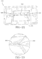
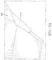
- Figures 22-24 illustrate an alternate embodiment of a die 800 and die insert 802.
- the die 800 and insert 802 together form a die outlet 804.
- the die outlet 804 is a thin rectangular shaped passage with corners 806.
- the die outlet corners 806 have chamfers 808 which enlarge the die width so that the die width is greater than the ply width.
- Figure 21 illustrates that the die outlet corners have a chamfer cone 810 which results in a localized increase in area.
- the improved cross-head die assembly provides for individually fed cord strands captured with through hole guide, with no sharp edges to break the cords.
- the invention allows for easy change out of a cord package in minutes while the elastomer remains isolated in the flow channels. A broken cord can be replaced without the need to rethread all of the remaining cords.
- the invention further provides for an integrated screen filter and replacable flow channel inserts which allow the flow balance of the system to be modified.
Landscapes
- Engineering & Computer Science (AREA)
- Mechanical Engineering (AREA)
- Manufacturing & Machinery (AREA)
- Textile Engineering (AREA)
- Extrusion Moulding Of Plastics Or The Like (AREA)
Abstract
Description
- This invention relates to pneumatic tires, and more particularly, the invention relates to ply constructions for tires.
- Modern passenger tires are typically constructed utilizing two or more layers of ply or a fabric woven from reinforcement filaments or cords. Such ply materials are typically made from an apparatus having a guide insert having passages through which the cabled reinforcement cords pass. If one of the reinforcement cords breaks, the apparatus typically needs to be disassembled, the guide insert removed, and then individually rethreading of the cords in the insert needs to occur. This procedure results in a significant loss on productivity. In addition, cords near the edge of the die can experience more drag, resulting in more stretch and distortion. Thus, it is desired to have an improved apparatus that allows replacement of one or more cords without the disruption of the remaining cords, and in a short period of time in order to minimize loss of production. It is also desired to have an improved apparatus that reduces clogging at the corners of the die inlet, which can reduce the effective die width and result in a nonuniform strip.
- The invention relates to a cross head die in accordance with claim 1 or 10 respectively and to a system in accordance with
claim 15. - Dependent claims refer to preferred embodiments of the invention.
- The invention provides in a first preferred aspect a cross-head die assembly for use with an extruder, the cross-head die assembly comprising: an inlet section having an inlet for receiving flow from the extruder; an upper support block removably connected to a first side of the interior section; and a lower block removably connected to a second side of the interior section; a first flow passage being located between the upper support block and the interior section and being in fluid communication with the inlet; a second flow passage being located between the interior section and the lower support block and being in fluid communication with the inlet; said cross-head die assembly further comprising a removably mounted die located at an outlet end of the assembly, said first and second flow passage being in fluid communication with an inlet of the die; said interior section further comprising an interior slot which extends from a first side of the assembly to the inlet of the die; and a removable cassette positioned in the interior slot.
- The invention provides in a second preferred aspect a cross-head die assembly for use with an extruder, the cross-head die assembly comprising: an inlet section having an inlet for communicating flow from the extruder to one or more flow channels formed in a support block; and an outlet, a removably mounted die located at the outlet and in fluid communication with the one or more flow channels; said support block further comprising an interior slot extending from a first side of the support block to an outlet passageway; a removable cassette positioned in the interior slot, wherein the front end of the removable cassette is positioned to seal the outlet passageway of the slot so that the slot is isolated from the flow.
- The invention provides in a third preferred aspect a cross-head die assembly for use with an extruder, the cross-head die assembly comprising: an inlet section having an inlet for communicating flow from the extruder to one or more flow channels formed in a support block; and an outlet, a removably mounted die located at the outlet and in fluid communication with the one or more flow channels; said support block further comprising an interior slot extending from a first side of the support block to an outlet passageway; a removable cassette positioned in the interior slot, wherein the front end of the removable cassette is positioned to seal the outlet passageway of the slot so that the slot is isolated from the flow.
- "Axial" and "axially" means the lines or directions that are parallel to the axis of rotation of the tire.
- "Cord" means one of the reinforcement strands, including fibers, which are used to reinforce the plies.
- "Ply" means a cord-reinforced layer of elastomer-coated, radially deployed or otherwise parallel reinforcement cords.
- "Radial" and "radially" mean directions radially toward or away from the axis of rotation of the tire.
- "Radial Ply Structure" means the one or more carcass plies or which at least one ply has reinforcing cords oriented at an angle of between 65° and 90° with respect to the equatorial plane of the tire.
- In the accompanying drawings:
-
Figure 1 is a perspective view of a cross-head die assembly shown with gear pump assembly in phantom. -
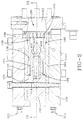
Figure 2 is a cross-sectional view of the cross-head die assembly ofFigure 1 in the direction 2-2. -
Figure 3 is a cross-sectional view of the cross head die assembly ofFigure 1 in the direction 3-3. -
Figure 4 is a cross-sectional view of the cross head die assembly ofFigure 1 in the direction 4-4. -
Figure 5 is a perspective, partially exploded view of the cross head die assembly ofFigure 1 showing the upper flow channel upper insert. -
Figure 6 is a perspective, partially exploded view of the cross head die assembly ofFigure 1 showing the upper flow channel lower insert. -
Figure 7 is a perspective view of the cross head die assembly ofFigure 1 showing the lower flow channel upper insert. -
Figure 8 is a rear view of the cross head die assembly offigure 1 showing the cord cassette removed. -
Figure 9 is a cross-sectional view of the cross head die assembly ofFigure 8 in the direction 9-9. -
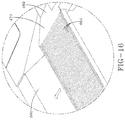
Figure 10 is a perspective view of the cross head die assembly ofFigure 1 showing the cords path through the cord cassette, and the cord guide and upper and lower dies. -
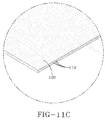
Figures 11A, 11B , and11C are close up views of the respective circled portions shown inFigure 10 . -
Figure 12 is a perspective view of the nose of the cassette, andFigure 12A is a close-up view of the nose lip and cord outlet. -
Figure 13A is a rear perspective view of the die and insert assembly, unassembled. -
Figure 13B is a rear perspective view of the die and insert assembly, assembled. -
Figure 13C is a front view of the die and insert assembly, assembled. -
Figure 14 is a side view of the cross-head die assembly shown with the block removed for accessing the filter. -
Figure 15 is a cross-sectional view of the cross-head die assembly ofFig 2 in the direction 15-15. -
Figure 16 is a close-up view of the lip of the nose of the cassette, showing the cord alignment grooves. -
Figure 17 is a front perspective view of a second embodiment of a die and insert assembly. -
Figure 18A is a front view of the die and insert assembly ofFig. 17 . -
Figure 18B is a cross-sectional view of the die and insert assembly ofFig. 18A in the direction 18A-18A. -
Figure 18C is a cross-sectional view of the die and insert assembly ofFig. 18A in thedirection 18C-18C. -
Figure 19 is a cross-sectional view of the die and insert assembly ofFig. 18A in the direction 19-19. -
Figure 20 is a top view of the die and insert assembly ofFigure 18A . -
Figure 21 is a cross-sectional view of the cross-head die assembly in the direction of the flow. -
Figures 22-24 illustrate an alternate embodiment of a die and die insert. -
Figure 1 illustrates a cross-head dieassembly 100 connected to an extruder assembly G shown in phantom. The assembly G preferably includes a gear pump and extruder combination, or an extruder. The assembly G supplies the elastomeric material to the cross-head die assembly. As shown inFigure 1 , a plurality ofparallel reinforcement cords 110 enter thecross-head die assembly 100 and are encased with elastomeric material to form a strip of reinforcedply material 120 which is output from theoutlet passageway 202 of the die 200. The strip may have a typical width of 80 mm with a thickness of 1.2 mm. - The
cross-head die assembly 100 has anupper support block 130, alower support block 140 and aninterior section 150. Aninlet section 160 is located on one end of the cross-head die assembly and is connected to theupper support block 130, thelower support block 140 and theinterior section 150. Theupper support block 130,lower support block 140 and the interior section are all removably connected to theassembly 100. - A cross-section of the
cross-head die assembly 100 is shown inFigure 2 . Theinlet section 160 has aninlet channel 162 for receiving elastomer material from an extruder (not shown) or extruder-gear pump assembly G. Theinlet channel 162 communicates elastomer flow to ascreen filter 164. As shown inFigure 14 , theinlet section 160 is easily removed from theassembly 100 without the need to completely disassemble the die assembly in order to replace or access thescreen filter 164. Thescreen filter 164 is easily removed and replaced. - As shown in
Figure 2 , elastomer flow from the extruder enters theassembly 100 and is separated into anupper flow channel 170 and alower flow channel 180. Theupper flow channel 170 is formed from a removableupper insert plate 172 and a removablelower insert plate 174. The removable upper insert plate 172 (Figure 5 ) preferably has a 90degree flow path 176 that cooperates with the preferably 90 degree flow path 178 (Figure 6 ) of thelower insert plate 174 to form theupper flow channel 170. Likewise, thelower flow channel 180 is formed between a removable upper insert plate 182 (Figure 7 ) and alower insert plate 184 with preferably 90 degree flow paths that cooperate to form thelower flow channel 180. Preferably, thelower insert plate 174 and theupper insert plate 182 have a taperedoutlet end lower flow channel cross-head assembly 100. As shown inFigure 1 , the profile die 200 has anoutlet hole 202 for exit of the ply strip from theassembly 100. - As shown in
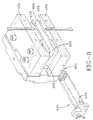
Figure 8 , thecross-head die assembly 100 has aremovable cassette 400 for feeding thereinforcement cords 110 into the cross-head die assembly in parallel alignment. Thecassette 400 is received in a rectangular shapedslot 402 located ininterior section 150. As shown inFigure 9 , therectangular slot 402 extends from theinlet side 402 of the cross-head die assembly to theoutlet side 404. Theslot 402 is separated and isolated from the elastomer flow in the upper andlower flow channels lower walls 410, 412 and first andsecond sidewalls Figure 10 illustrates thecords 110 in thecassette 400. Thecords 110 are threaded in theslot 451 ofcord guide 450 as shown infigure 11A , wherein the slot hasinner surfaces 452 having alignment edges 454 (Figure 15 ) which maintain the spacing of the cords. The front end of the cassette has anose 460 as shown inFigures 8 ,12 and 12a . Thenose 460 is detachable from the cassette. Thenose 460 has a row of closely spaced outlet holes 462, wherein eachhole 462 receives a cord. The outlet holes 462 are positioned adjacent alip 471 which protrudes axially from the outer surface of the nose. Thelip 471 is formed by the removal or relief of a portion of the upper surface of the nose. A plurality ofalignment groove 464 are positioned on thelip 471 adjacent eachoutlet hole 462. Thealignment groove 464 extends through the hole as shown inFigures 12 ,13 and16 . Thealignment grooves 464 together with the outlet holes 462 maintain the proper separation, spacing and alignment of each individual cord so that the reinforcement ply strip is formed with parallel and properly spaced cords as shown inFigure 11C . Further, the individual holes for each cord allow for the easy replacement of a single broken cord without disrupting the remaining cords. - The
nose 460 of the cassette is positioned adjacent thedie assembly 200. As shown inFigures 4 and13 , therear face 201 of thedie 200 has angledpassageways 204 for communicating elastomer through thedie outlet hole 202. Thedie assembly 200 further includes aninsert 500 which is removably mounted in aslot 504 thedie assembly 200. The insert has flanged ends 502 which are positioned in the slot ends 506.Fasteners 507 are jacking screws to assist in pressing the insert out of the die assembly for cord change. Theinsert 500 has afront sealing edge 510 that is positioned in theinsert slot 504. Theinsert 500 functions to seal the die edges to prevent leakage, particularly near the edges of the die. As pressure increases in the die assembly, the insert is pushed further into the die, resulting in theinsert sealing edge 510 forming a seal with the die edges 220 located around theoutlet hole 202. The insert has alower face 512 that forms part of theangled passageway 204 when the insert is snapped into the die. Thelower portion 514 of thelower face 512 forms the upper portion of thedie outlet hole 202. - The
nose 460 of the cassette has an upper and lower outer contouredsurface contoured surface 461 of the nose is positioned adjacent theangled passageway 204. As the elastomer flows from the upper and lower channel, it is squeezed through theangled passageway 204 and along the outer contoured surface 461,465 of thenose 460. The elastomer flows down the upper outer surface of the nose, and then meets the cords at thelip 471 and encapsulates thereinforcement cords 110 along thelip 471. Thealignment grooves 464 of thelip 471 maintain stability by retaining the cord spacing and alignment while the elastomer flows onto the cords. The flow from the bottom channel flows along the bottom surface of the nose and meets the cord after the upper portion of the cords have already been coated with rubber. The elastomer and cords then pass through theangled passageway 204 and then through thedie outlet hole 202. - The
die 200 is removable to allow for easier cord threading. If a cord breaks or the cords need to be changed out, the cassette can be easily removed from the assembly. Thedie 200 and insert 500 can also be removed for cord change. If a cord is broken, it can be rethreaded into theguide 450 and theoutlet hole 462 of the cassette. A broken cord can be replaced without rethreading the remaining cords. When the cassette is removed, the rubber or elastomer remains isolated in the flow channels. A complete change out of the cord package may occur within 5 minutes. The flow channel inserts may also be changed out. - As shown in
Figures 2 ,3 , thecross-head die assembly 100 may further comprise one or more cooling/heating channels 300 with acoolant inlet 302 andcoolant exit 304. - An alternate embodiment die
insert 600 in shown inFigure 17 . Theinsert 600 can be removably inserted in aslot 504 thedie assembly 200. Theinsert 600 has flanged outer ends 602 which are positioned in the slot ends 506. As shown inFigure 18 , theinsert 600 has afront sealing edge 610 that is positioned in theinsert slot 504. Theinsert 600 functions to seal the die edges to prevent leakage, particularly near the edges of the die. As pressure increases in the die assembly, the insert is pushed further into the die, resulting in theinsert sealing edge 610 forming a seal with the die edges 220 located around theoutlet hole 202. The insert has alower face 612 that forms part of theangled passageway 204 when the insert is snapped into the die. Thelower portion 614 of thelower face 612 forms the upper portion of thedie outlet hole 202. The outer ends 602 have an interior wing shapedportion 616 that is in the flow path of the rubber. The wing shapedportions 616 outwardly project and extend into the flow path. Thedie insert 600 further includes twoedge flow channels 620 formed in the corner between thelower face 612 and the wing shapedportion 616 of the dieouter end 602. Eachedge flow channel 620 forms a V shaped slit between the wing shapedportion 616 and thelower face 612. The opening of the edge flow channel faces the die outlet. Theangled passageway 704 adjacent eachedge flow channel 620 has an internal chamfer in eachcorner 710. Thus theedge flow channels 620 together with the chamferedcorners 710 increase the flow area at the outer corners of the die. This increased flow area increases the rubber flow and reduces drag. -
Figures 22-24 illustrate an alternate embodiment of adie 800 and dieinsert 802. Thedie 800 and insert 802 together form a die outlet 804. The die outlet 804 is a thin rectangular shaped passage withcorners 806. Thedie outlet corners 806 have chamfers 808 which enlarge the die width so that the die width is greater than the ply width.Figure 21 illustrates that the die outlet corners have a chamfer cone 810 which results in a localized increase in area. - In summary, the improved cross-head die assembly provides for individually fed cord strands captured with through hole guide, with no sharp edges to break the cords. The invention allows for easy change out of a cord package in minutes while the elastomer remains isolated in the flow channels. A broken cord can be replaced without the need to rethread all of the remaining cords. The invention further provides for an integrated screen filter and replacable flow channel inserts which allow the flow balance of the system to be modified.
Claims (15)
- A cross-head die assembly for use with an extruder, the cross-head die assembly comprising an inlet section having an inlet for receiving flow, an upper support block removably connected to a first side of the interior section, and a lower block removably connected to a second side of the interior section, wherein a first flow passage is located between the upper support block and the interior section and is in fluid communication with the inlet, wherein a second flow passage is located between the interior section and the lower support block and is in fluid communication with the inlet, wherein the cross-head die assembly further comprises a removably mounted profile die located at an outlet end of the assembly, said first and second flow passage being in fluid communication with an inlet of the profile die, and wherein the interior section further comprises an interior slot which extends from a first side of the assembly to the inlet of the die and a removable cassette positioned in the interior slot.
- The cross-head die assembly of claim 1 wherein the upper support block and/or the lower support block has a removable flow insert plate.
- The cross-head die assembly of claim 1 or 2 wherein the first side of the interior section and/or the second side of the interior section has a removable flow insert plate.
- The cross-head die assembly of at least one of the previous claims wherein the cassette has a plurality of holes for receiving a ply cord, and, optionally, wherein each hole has an alignment groove which extends though said hole.
- The cross-head die assembly of at least one of the previous claims wherein the slot has upper and lower sidewalls and lateral sidewalls.
- The cross-head die assembly of at least one of the previous claims wherein the slot has an outlet end and wherein a nose of the cassette seals the outlet of the slot from flow so that the slot is isolated from the flow.
- The cross-head die assembly of at least one of the previous claims wherein the profile die has a removable insert.
- The cross-head die assembly of claim 7 wherein the removable insert has a lower surface forming a portion of the die outlet together with the die, wherein the removable insert has opposed corners, and wherein each corner has a chamfer.
- The cross-head die assembly of claim 7 or 8 wherein the removable insert has a sealing edge positioned against the die outlet hole.
- A cross-head die assembly for use with an extruder, the cross-head die assembly comprising an inlet section having an inlet for communicating flow from the extruder to one or more flow channels formed in a support block, an outlet, and a removably mounted die or profile die located at the outlet and in fluid communication with the one or more flow channels, wherein the support block further comprises an interior slot extending from a first side of the support block to an outlet passageway, wherein a removable cassette is positioned in the interior slot, and wherein the front end of the removable cassette is positioned to seal the outlet passageway of the slot so that the slot is isolated from the flow.
- The cross-head die assembly of claim 10 wherein the cassette has a plurality of holes, wherein each hole receives a ply cord.
- The cross-head die assembly of claim 11 wherein each hole has an alignment groove which extends though said hole, and, optionally, wherein the slot has upper and lower sidewalls and lateral sidewalls.
- The cross-head die assembly of claim 10, 11 or 12 wherein the profile die has a removable insert having a lower surface forming a portion of the die outlet together with the die, wherein the removable insert has opposed corners, and wherein each corner has a chamfer.
- The cross head die assembly of 10, 11, 12 or 13 wherein said die has a removable insert having a lower surface forming a portion of the die outlet together with the die, wherein the removable insert has opposed corners, and wherein each corner has a chamfer.
- A system comprising an extruder and a cross head die assembly in accordance with at least one of the previous claims
Applications Claiming Priority (1)
| Application Number | Priority Date | Filing Date | Title |
|---|---|---|---|
| US14/575,063 US9770859B2 (en) | 2014-12-18 | 2014-12-18 | Apparatus for producing laminated fabric ply strips |
Publications (1)
| Publication Number | Publication Date |
|---|---|
| EP3034268A1 true EP3034268A1 (en) | 2016-06-22 |
Family
ID=55027324
Family Applications (1)
| Application Number | Title | Priority Date | Filing Date |
|---|---|---|---|
| EP15200484.2A Withdrawn EP3034268A1 (en) | 2014-12-18 | 2015-12-16 | Apparatus for producing laminated fabric ply strips |
Country Status (4)
| Country | Link |
|---|---|
| US (1) | US9770859B2 (en) |
| EP (1) | EP3034268A1 (en) |
| CN (1) | CN105711058B (en) |
| BR (1) | BR102015031063B1 (en) |
Cited By (3)
| Publication number | Priority date | Publication date | Assignee | Title |
|---|---|---|---|---|
| EP3338996A1 (en) * | 2016-12-20 | 2018-06-27 | The Goodyear Tire & Rubber Company | Apparatus for producing laminated fabric ply strips |
| NL2018638B1 (en) * | 2017-04-03 | 2018-10-11 | Vmi Holland Bv | Extruder system and method for extruding cord-reinforced tire components |
| WO2018184955A1 (en) * | 2017-04-03 | 2018-10-11 | Vmi Holland B.V. | Extruder system and method for extruding cord-reinforced tire components |
Families Citing this family (4)
| Publication number | Priority date | Publication date | Assignee | Title |
|---|---|---|---|---|
| US10518457B2 (en) | 2016-05-23 | 2019-12-31 | The Goodyear Tire & Rubber Company | Crosshead die |
| NL2016826B1 (en) * | 2016-05-25 | 2017-12-12 | Vmi Holland Bv | Extruder head for extruding cord-reinforced extrudate |
| US20210387395A1 (en) * | 2020-06-10 | 2021-12-16 | The Goodyear Tire & Rubber Company | Die for a polymer mixing machine and tire ply produced by same |
| WO2025051631A1 (en) | 2023-09-08 | 2025-03-13 | Saint-Gobain Glass France | Installable extruder head for extruder |
Citations (6)
| Publication number | Priority date | Publication date | Assignee | Title |
|---|---|---|---|---|
| JPS4323745Y1 (en) * | 1964-02-14 | 1968-10-07 | ||
| US4150929A (en) * | 1977-06-22 | 1979-04-24 | B & H Tool Company, Inc. | Ribbon cable extrusion apparatus |
| US4274821A (en) * | 1980-02-28 | 1981-06-23 | The Steelastic Company | Die for extruding reinforced fabric |
| EP0503541A1 (en) * | 1991-03-15 | 1992-09-16 | Bridgestone/Firestone, Inc. | Extrusion head for producing tread plies for road vehicle tires |
| US7056110B2 (en) * | 2001-10-08 | 2006-06-06 | Bridgestone/Firestone North American Tire, Llc | Apparatus for making reinforcement ply material |
| EP2253450A1 (en) * | 2009-05-22 | 2010-11-24 | VMI - AZ Extrusion GmbH | Extrusion coating device with adjustable die lips |
Family Cites Families (45)
| Publication number | Priority date | Publication date | Assignee | Title |
|---|---|---|---|---|
| US3112527A (en) * | 1961-09-27 | 1963-12-03 | Dow Chemical Co | Adjustable flexible orifice for extrusion of foam plastics |
| US3859017A (en) * | 1969-02-20 | 1975-01-07 | Rol | Extrusion of sheath onto elongated support using decompression zones |
| US3752614A (en) * | 1971-02-02 | 1973-08-14 | Bremertron Kl Corp | Adjustable extrusion head |
| US3888713A (en) | 1972-05-24 | 1975-06-10 | Steelastic Co | Method for producing reinforced fabric |
| JPS56154532A (en) | 1980-04-24 | 1981-11-30 | Sumitomo Rubber Ind | Rubber reinforcing tire fabric |
| US4525131A (en) * | 1983-08-29 | 1985-06-25 | Alcan Aluminum Corporation | Cable-coating extruder head system with changeable die and guider elements |
| FR2598652B1 (en) * | 1986-05-16 | 1988-08-05 | Figuereo Blaise | MULTI-MATERIAL SIMULTANEOUS EXTRUSION MACHINE |
| IT1219242B (en) | 1988-04-27 | 1990-05-03 | Firestone Int Dev Spa | EXTRUSION HEAD FOR INTERNALLY ARMORED SHEET MATERIAL WITH ELEMENTS IN REINFORCEMENT WIRE DISTRIBUTED WITH RELATIVELY REDUCED PITCH |
| US5804222A (en) * | 1997-04-29 | 1998-09-08 | Brown; Jearl D. | Co-extrusion head for coating wire |
| DE19719220C2 (en) * | 1997-05-07 | 1999-09-16 | Troester Maschf Paul | Crosshead of an extrusion line |
| JPH1199564A (en) | 1997-09-26 | 1999-04-13 | Yokohama Rubber Co Ltd:The | Pneumatic radial tire and method of manufacturing the same |
| USD423422S (en) | 1999-06-22 | 2000-04-25 | The Goodyear Tire & Rubber Company | Tire thread |
| USD432956S (en) | 1999-07-07 | 2000-10-31 | Michelin Recherche Et Technique, S.A. | Tread of a tire |
| ES2218064T3 (en) | 2000-11-29 | 2004-11-16 | Pirelli Pneumatici Societ Per Azioni | PROCEDURE AND DEVICE FOR THE MANUFACTURE OF A WAIST STRUCTURE FOR A TIRE RIM. |
| USD451441S1 (en) | 2000-12-04 | 2001-12-04 | The Goodyear Tire & Rubber Company | Tire tread |
| USD453729S1 (en) | 2001-05-18 | 2002-02-19 | The Goodyear Tire & Rubber Company | Tire tread |
| JP2005246736A (en) | 2004-03-03 | 2005-09-15 | Toyo Tire & Rubber Co Ltd | Ply cord manufacturing apparatus and ply cord manufacturing method |
| WO2006114117A1 (en) | 2005-04-27 | 2006-11-02 | Pirelli Tyre S.P.A. | Method for extruding a polymeric material and extrusion head therefor |
| USD583755S1 (en) | 2006-03-31 | 2008-12-30 | The Goodyear Tire & Rubber Company | Tire for automobile |
| USD559767S1 (en) | 2006-08-01 | 2008-01-15 | The Goodyear Tire & Rubber Company | Tire tread |
| USD609627S1 (en) | 2007-11-22 | 2010-02-09 | Michelin Recherche Et Technique S.A. | Pneumatic tire |
| USD609161S1 (en) | 2008-03-19 | 2010-02-02 | The Goodyear Tire & Rubber Company | Tire |
| USD601939S1 (en) | 2008-03-19 | 2009-10-13 | The Goodyear Tire & Rubber Company | Tire |
| USD599276S1 (en) | 2009-02-27 | 2009-09-01 | The Goodyear Tire & Rubber Company | Tire |
| USD634699S1 (en) | 2009-02-27 | 2011-03-22 | The Goodyear Tire & Rubber Company | Tire |
| USD650322S1 (en) | 2009-09-10 | 2011-12-13 | Toyo Tire & Rubber Co., Ltd. | Tire |
| USD626910S1 (en) | 2009-10-02 | 2010-11-09 | The Goodyear Tire & Rubber Company | Tire |
| USD647456S1 (en) | 2010-02-02 | 2011-10-25 | Continental Reifen Deutschland Gmbh | Tire tread for a vehicle tire |
| USD643800S1 (en) | 2010-04-29 | 2011-08-23 | Itochu Corporation | Tire |
| USD659633S1 (en) | 2010-05-27 | 2012-05-15 | The Goodyear Tire & Rubber Company | Tire |
| USD638348S1 (en) | 2010-12-20 | 2011-05-24 | The Goodyear Tire & Rubber Company | Tire |
| USD644593S1 (en) | 2010-12-20 | 2011-09-06 | The Goodyear Tire & Rubber Company | Tire |
| USD639719S1 (en) | 2010-12-20 | 2011-06-14 | The Goodyear Tire & Rubber Company | Tire |
| USD639720S1 (en) | 2010-12-20 | 2011-06-14 | The Goodyear Tire & Rubber Company | Tire |
| AU337703S (en) | 2011-02-14 | 2011-07-18 | Sumitomo Rubber Ind | Tyre for an automobile |
| USD665335S1 (en) | 2011-09-01 | 2012-08-14 | The Goodyear Tire & Rubber Company | Tire |
| USD665336S1 (en) | 2011-09-30 | 2012-08-14 | The Goodyear Tire & Rubber Company | Tire |
| USD692371S1 (en) | 2012-03-01 | 2013-10-29 | The Goodyear Tire & Rubber Company | Tire |
| USD667358S1 (en) | 2012-04-02 | 2012-09-18 | The Goodyear Tire & Rubber Company | Tire |
| USD668598S1 (en) | 2012-04-12 | 2012-10-09 | The Goodyear Tire & Rubber Company | Tire |
| USD679241S1 (en) | 2012-11-06 | 2013-04-02 | The Goodyear Tire & Rubber Company | Tire |
| USD689430S1 (en) | 2013-02-28 | 2013-09-10 | The Goodear Tire & Rubber Company | Tire |
| USD694702S1 (en) | 2013-04-11 | 2013-12-03 | The Goodyear Tire & Rubber Company | Tire |
| USD730269S1 (en) | 2014-04-17 | 2015-05-26 | The Goodyear Tire & Rubber Company | Tire |
| USD728453S1 (en) | 2014-05-12 | 2015-05-05 | The Goodyear Tire & Rubber Company | Tire |
-
2014
- 2014-12-18 US US14/575,063 patent/US9770859B2/en active Active
-
2015
- 2015-12-11 BR BR102015031063-3A patent/BR102015031063B1/en not_active IP Right Cessation
- 2015-12-16 EP EP15200484.2A patent/EP3034268A1/en not_active Withdrawn
- 2015-12-18 CN CN201510949739.1A patent/CN105711058B/en active Active
Patent Citations (6)
| Publication number | Priority date | Publication date | Assignee | Title |
|---|---|---|---|---|
| JPS4323745Y1 (en) * | 1964-02-14 | 1968-10-07 | ||
| US4150929A (en) * | 1977-06-22 | 1979-04-24 | B & H Tool Company, Inc. | Ribbon cable extrusion apparatus |
| US4274821A (en) * | 1980-02-28 | 1981-06-23 | The Steelastic Company | Die for extruding reinforced fabric |
| EP0503541A1 (en) * | 1991-03-15 | 1992-09-16 | Bridgestone/Firestone, Inc. | Extrusion head for producing tread plies for road vehicle tires |
| US7056110B2 (en) * | 2001-10-08 | 2006-06-06 | Bridgestone/Firestone North American Tire, Llc | Apparatus for making reinforcement ply material |
| EP2253450A1 (en) * | 2009-05-22 | 2010-11-24 | VMI - AZ Extrusion GmbH | Extrusion coating device with adjustable die lips |
Cited By (9)
| Publication number | Priority date | Publication date | Assignee | Title |
|---|---|---|---|---|
| EP3338996A1 (en) * | 2016-12-20 | 2018-06-27 | The Goodyear Tire & Rubber Company | Apparatus for producing laminated fabric ply strips |
| JP2018099886A (en) * | 2016-12-20 | 2018-06-28 | ザ・グッドイヤー・タイヤ・アンド・ラバー・カンパニー | Equipment for producing ply strip made of laminated fabric |
| JP6994927B2 (en) | 2016-12-20 | 2022-02-04 | ザ・グッドイヤー・タイヤ・アンド・ラバー・カンパニー | Equipment for manufacturing ply strips made of laminated cloth |
| NL2018638B1 (en) * | 2017-04-03 | 2018-10-11 | Vmi Holland Bv | Extruder system and method for extruding cord-reinforced tire components |
| WO2018184955A1 (en) * | 2017-04-03 | 2018-10-11 | Vmi Holland B.V. | Extruder system and method for extruding cord-reinforced tire components |
| KR20190129128A (en) * | 2017-04-03 | 2019-11-19 | 브이엠아이 홀랜드 비.브이. | Extruder system and method for extruding cord reinforced tire components |
| RU2766178C2 (en) * | 2017-04-03 | 2022-02-08 | Вми Холланд Б.В. | Extrusion system and method for extrusion of tire components reinforced with cords |
| US11400631B2 (en) | 2017-04-03 | 2022-08-02 | Vmi Holland B.V. | Extruder system and method for extruding cord-reinforced tire components |
| KR20230033735A (en) * | 2017-04-03 | 2023-03-08 | 브이엠아이 홀랜드 비.브이. | Extruder system and method for extruding cord-reinforced tire components |
Also Published As
| Publication number | Publication date |
|---|---|
| CN105711058A (en) | 2016-06-29 |
| US9770859B2 (en) | 2017-09-26 |
| CN105711058B (en) | 2018-12-28 |
| US20160176096A1 (en) | 2016-06-23 |
| BR102015031063B1 (en) | 2020-11-10 |
| BR102015031063A2 (en) | 2016-12-27 |
Similar Documents
| Publication | Publication Date | Title |
|---|---|---|
| EP2995439B1 (en) | Apparatus and method for producing laminated fabric ply strips | |
| US9770859B2 (en) | Apparatus for producing laminated fabric ply strips | |
| EP3037241B1 (en) | Extruder die assembly and method of manufacturing a tire tread | |
| US20210197438A1 (en) | Method for co-extruding complex rubber profile for manufacturing a tire | |
| US4892473A (en) | Head for extrusion of elastomeric contour innerliner | |
| US12583166B2 (en) | Method and apparatus for forming tire components using a coextruded strip | |
| US10596740B2 (en) | Co-extrusion head for co-extruding complex rubber profile section for manufacturing a tire | |
| US8197242B2 (en) | Device and method for sheathing a ply of threads | |
| EP3338996B1 (en) | Apparatus for producing laminated fabric ply strips | |
| EP0046688B1 (en) | Extrusion die | |
| CN111263692B (en) | Extrusion head for complex forming elements formed from juxtaposed forming elements | |
| EP3248753B1 (en) | Crosshead die and method of extruding a profile using such a crosshead die | |
| KR101952201B1 (en) | Method and apparatus for manufacturing rubber extruded member | |
| EP3670141B1 (en) | Methods of making composite innerliner and tire having such a composite innerliner | |
| JP6859733B2 (en) | Topping device and topping method | |
| US10967594B2 (en) | Head for the co-extrusion of a complex rubber profiled element intended for the manufacture of a tire | |
| US20170173837A1 (en) | Extruder die assembly | |
| KR20180085431A (en) | Extrusion Apparatus for Capply |
Legal Events
| Date | Code | Title | Description |
|---|---|---|---|
| PUAI | Public reference made under article 153(3) epc to a published international application that has entered the european phase |
Free format text: ORIGINAL CODE: 0009012 |
|
| AK | Designated contracting states |
Kind code of ref document: A1 Designated state(s): AL AT BE BG CH CY CZ DE DK EE ES FI FR GB GR HR HU IE IS IT LI LT LU LV MC MK MT NL NO PL PT RO RS SE SI SK SM TR |
|
| AX | Request for extension of the european patent |
Extension state: BA ME |
|
| STAA | Information on the status of an ep patent application or granted ep patent |
Free format text: STATUS: REQUEST FOR EXAMINATION WAS MADE |
|
| 17P | Request for examination filed |
Effective date: 20161222 |
|
| RBV | Designated contracting states (corrected) |
Designated state(s): AL AT BE BG CH CY CZ DE DK EE ES FI FR GB GR HR HU IE IS IT LI LT LU LV MC MK MT NL NO PL PT RO RS SE SI SK SM TR |
|
| STAA | Information on the status of an ep patent application or granted ep patent |
Free format text: STATUS: EXAMINATION IS IN PROGRESS |
|
| 17Q | First examination report despatched |
Effective date: 20200909 |
|
| RAP3 | Party data changed (applicant data changed or rights of an application transferred) |
Owner name: THE GOODYEAR TIRE & RUBBER COMPANY |
|
| STAA | Information on the status of an ep patent application or granted ep patent |
Free format text: STATUS: THE APPLICATION IS DEEMED TO BE WITHDRAWN |
|
| 18D | Application deemed to be withdrawn |
Effective date: 20221122 |