EP3034222A1 - Electric discharge machine - Google Patents
Electric discharge machine Download PDFInfo
- Publication number
- EP3034222A1 EP3034222A1 EP15200065.9A EP15200065A EP3034222A1 EP 3034222 A1 EP3034222 A1 EP 3034222A1 EP 15200065 A EP15200065 A EP 15200065A EP 3034222 A1 EP3034222 A1 EP 3034222A1
- Authority
- EP
- European Patent Office
- Prior art keywords
- cleaning
- machining
- robot
- fluid
- control device
- Prior art date
- Legal status (The legal status is an assumption and is not a legal conclusion. Google has not performed a legal analysis and makes no representation as to the accuracy of the status listed.)
- Withdrawn
Links
- 238000003754 machining Methods 0.000 claims abstract description 139
- 238000004140 cleaning Methods 0.000 claims abstract description 108
- 239000012530 fluid Substances 0.000 claims abstract description 96
- 238000002347 injection Methods 0.000 claims abstract description 11
- 239000007924 injection Substances 0.000 claims abstract description 11
- 238000003860 storage Methods 0.000 claims description 13
- XLYOFNOQVPJJNP-UHFFFAOYSA-N water Substances O XLYOFNOQVPJJNP-UHFFFAOYSA-N 0.000 claims description 9
- 230000001360 synchronised effect Effects 0.000 claims description 4
- 238000001514 detection method Methods 0.000 claims description 3
- 238000002360 preparation method Methods 0.000 claims description 3
- 238000007599 discharging Methods 0.000 claims description 2
- 238000010586 diagram Methods 0.000 description 6
- 238000011109 contamination Methods 0.000 description 3
- 230000006866 deterioration Effects 0.000 description 2
- 230000000694 effects Effects 0.000 description 2
- 238000007789 sealing Methods 0.000 description 2
- 239000002131 composite material Substances 0.000 description 1
- 230000002708 enhancing effect Effects 0.000 description 1
- 238000000034 method Methods 0.000 description 1
- 239000008400 supply water Substances 0.000 description 1
Images




Classifications
-
- B—PERFORMING OPERATIONS; TRANSPORTING
- B23—MACHINE TOOLS; METAL-WORKING NOT OTHERWISE PROVIDED FOR
- B23H—WORKING OF METAL BY THE ACTION OF A HIGH CONCENTRATION OF ELECTRIC CURRENT ON A WORKPIECE USING AN ELECTRODE WHICH TAKES THE PLACE OF A TOOL; SUCH WORKING COMBINED WITH OTHER FORMS OF WORKING OF METAL
- B23H7/00—Processes or apparatus applicable to both electrical discharge machining and electrochemical machining
- B23H7/36—Supply or regeneration of working media
-
- B—PERFORMING OPERATIONS; TRANSPORTING
- B23—MACHINE TOOLS; METAL-WORKING NOT OTHERWISE PROVIDED FOR
- B23H—WORKING OF METAL BY THE ACTION OF A HIGH CONCENTRATION OF ELECTRIC CURRENT ON A WORKPIECE USING AN ELECTRODE WHICH TAKES THE PLACE OF A TOOL; SUCH WORKING COMBINED WITH OTHER FORMS OF WORKING OF METAL
- B23H11/00—Auxiliary apparatus or details, not otherwise provided for
-
- B—PERFORMING OPERATIONS; TRANSPORTING
- B08—CLEANING
- B08B—CLEANING IN GENERAL; PREVENTION OF FOULING IN GENERAL
- B08B3/00—Cleaning by methods involving the use or presence of liquid or steam
- B08B3/02—Cleaning by the force of jets or sprays
- B08B3/024—Cleaning by means of spray elements moving over the surface to be cleaned
-
- B—PERFORMING OPERATIONS; TRANSPORTING
- B23—MACHINE TOOLS; METAL-WORKING NOT OTHERWISE PROVIDED FOR
- B23H—WORKING OF METAL BY THE ACTION OF A HIGH CONCENTRATION OF ELECTRIC CURRENT ON A WORKPIECE USING AN ELECTRODE WHICH TAKES THE PLACE OF A TOOL; SUCH WORKING COMBINED WITH OTHER FORMS OF WORKING OF METAL
- B23H1/00—Electrical discharge machining, i.e. removing metal with a series of rapidly recurring electrical discharges between an electrode and a workpiece in the presence of a fluid dielectric
- B23H1/10—Supply or regeneration of working media
-
- B—PERFORMING OPERATIONS; TRANSPORTING
- B23—MACHINE TOOLS; METAL-WORKING NOT OTHERWISE PROVIDED FOR
- B23Q—DETAILS, COMPONENTS, OR ACCESSORIES FOR MACHINE TOOLS, e.g. ARRANGEMENTS FOR COPYING OR CONTROLLING; MACHINE TOOLS IN GENERAL CHARACTERISED BY THE CONSTRUCTION OF PARTICULAR DETAILS OR COMPONENTS; COMBINATIONS OR ASSOCIATIONS OF METAL-WORKING MACHINES, NOT DIRECTED TO A PARTICULAR RESULT
- B23Q11/00—Accessories fitted to machine tools for keeping tools or parts of the machine in good working condition or for cooling work; Safety devices specially combined with or arranged in, or specially adapted for use in connection with, machine tools
- B23Q11/0042—Devices for removing chips
Definitions
- the present invention relates to an electric discharge machine. Specifically, the present invention relates to an electric discharge machine having a function to clean the inside of a machining tank.
- the electric discharge machine is a machine tool for machining a workpiece by generating an electric discharge between a tool electrode and the workpiece.
- the tool electrode includes, for example, a wire electrode.
- the workpiece is machined while the workpiece is immersed in machining fluid. Alternatively, the workpiece is machined while the machining fluid is ejected to the workpiece. Therefore, electric discharge machining is performed in a machining tank.
- Machining chips are produced during the electric discharge machining.
- the machining chips contaminating the machining fluid stick to each part inside the machining tank. If the machining chips stuck to the machining tank are left as they are, a variety of accuracy deterioration and machine trouble may be caused.
- the machining chips fixed to a workpiece table may deteriorate fixing accuracy of the workpiece.
- the machining chips fixed to a sealing part of the machining tank may increase a load on the sealing part, or cause water leakage. Therefore, a cleaning operation inside the machining tank is essential for using the electric discharge machine continuously.
- JP 2009-255223 A discloses a technique to clean off the machining chips in a composite machining device having a machining tank which is used in common for water jet machining and wire-cut electric discharge machining.
- the machining tank is provided with a water channel.
- An opening is provided in the water channel so as to supply water to the water channel.
- the water in the water channel flows down along an inner wall surface of a tank wall of the machining tank so as to clean off the machining chips.
- the device since the water channel is required to be provided in the machining tank, the device becomes complicated and large.
- the inside of the machining tank is cleaned by using a cleaning device, in which the machining fluid is pumped by a pump from a machining fluid tank provided in the electric discharge machine so that the machining fluid is ejected from a cleaning gun.
- a user of the electric discharge machine operates the cleaning gun to eject the machining fluid, by which contamination due to, for example, the machining chips stuck to each part inside the machining tank is cleaned off, thereby preventing the machine trouble and the accuracy deterioration caused by the contamination in the machining tank.
- an object of the present invention is to provide an electric discharge machine employing an automated cleaning operation by having a robot system for cleaning the inside of a machining tank.
- the robot system is synchronized with the electric discharge machine.
- An electric discharge machine machines a workpiece by immersing the workpiece in machining fluid or by ejecting the machining fluid to the workpiece, the electric discharge machine including: a cleaning device configured to inject the machining fluid or cleaning fluid; a robot device configured to move an injection nozzle of the cleaning device; a robot control device configured to control the robot device; and a control device configured to control the cleaning device.
- the control device may include a robot motion recognition part configured to acquire and recognize motion or position information of the robot device from the robot control device; a storage device configured to store a pressure condition or a flow rate condition of the machining fluid or the cleaning fluid corresponding to the motion or position information of the robot device; a cleaning fluid pressure determination part configured to determine a pressure or a flow rate of the machining fluid or the cleaning fluid based on the motion or position information of the robot device, and on the condition stored in the storage device; and a cleaning fluid pressure adjusting device configured to adjust the cleaning fluid, to be injected by the cleaning device, to the pressure or the flow rate of the machining fluid or the cleaning fluid determined by the cleaning fluid pressure determination part, and the control device may adjust the pressure or the flow rate of the cleaning fluid in accordance with a place to be cleaned.
- a robot motion recognition part configured to acquire and recognize motion or position information of the robot device from the robot control device
- a storage device configured to store a pressure condition or a flow rate condition of the machining fluid or the cleaning fluid corresponding to the
- the control device may include a position driving part capable of driving a position of an electrode supporting part that supports an electrode configured to perform electric discharge machining; a robot motion recognition part; a storage device configured to store a position condition of the electrode supporting part corresponding to a motion of the robot device; and a position determination part configured to determine the position of the electrode supporting part based on the motion information of the robot device obtained from the robot motion recognition part, and on the condition read from the storage device, the position determination part being provided in the control device configured to control the position driving part, and the control device may be synchronized with the motion of the robot device so as to move a machining tank or the electrode supporting part.
- the robot control device may include a machining tank recognition part configured to recognize a state inside the machining tank from information obtained from a water level detection device configured to detect a water level of the machining fluid inside the machining tank; a cleaning determination part configured to determine whether automatic cleaning is to be started based on information obtained from the machining tank recognition part; and a cleaning preparation command part configured to command the control device to discharge the machining fluid from the machining tank based on a content determined by the cleaning determination part, and the robot control device may determine whether the machining fluid is stored in the machining tank before an automatic cleaning operation is started, and when stored, the automatic cleaning is performed after discharging the machining fluid.
- the present invention including the above-mentioned configuration has a robot system synchronized with the electric discharge machine for cleaning the inside of the machining tank. Therefore, the present invention can provide the electric discharge machine employing the automated cleaning operation.
- FIG. 1 is a view illustrating an electric discharge machine according to an embodiment of the present invention.
- FIG. 2 is a view illustrating an exemplary embodiment of a robot device equipped with an injection nozzle of a cleaning device.
- FIG. 1 is the view illustrating the electric discharge machine having a cleaning system by a robot.
- a wire electric discharge machine is exemplified in the first embodiment, this embodiment is applicable to any machining device as long as it is an electric discharge machine. The same shall apply to the other embodiments.
- the electric discharge machine includes a machining tank 1 for immersing a workpiece in machining fluid.
- the machining tank 1 is provided with electrode supporting parts 2, 3 and a workpiece table 4.
- the electrode supporting parts 2, 3 support a wire electrode for machining.
- the workpiece table 4 fixes the workpiece thereon.
- Position driving parts 6, 7, 8, 9, 10 are driven by a control device 5 with position control.
- the position driving parts 6, 7, 8, 9, 10 control positions of the wire electrode and the workpiece mounted on the workpiece table 4.
- the position driving part 6 is a Y-axis driving part, which moves the machining tank 1 in a direction parallel and lateral to a paper surface together with an X-axis driving part.
- the position driving part 7 is the X-axis driving part, which moves the machining tank 1 in a direction vertical to the paper surface.
- the position driving part 8 is a V-axis driving part, which moves the upper electrode supporting part 2 in a direction parallel to a Y-axis together with a U-axis driving part and a Z-axis driving part.
- the position driving part 9 is the U-axis driving part, which moves the upper electrode supporting part 2 in a direction parallel to an X-axis together with the Z-axis driving part.
- the position driving part 10 is the Z-axis driving part, which moves the upper electrode supporting part 2 in a direction parallel and longitudinal to the paper surface.
- a cleaning device is a device to pump the machining fluid by a pump 12 from a tank 11 in which the machining fluid is stored.
- the cleaning device then ejects the machining fluid from a cleaning fluid injection nozzle 13.
- the ejection can be controlled by controlling the pump 12 with the control device 5.
- fluid having a higher cleaning effect may be used as cleaning fluid.
- the robot device includes a robot driving part 15.
- a robot arm can be operated freely by driving the robot driving part 15.
- a motion of the robot device is controlled by a robot control device 16 giving a position command to the robot driving part 15.
- the robot device may include the cleaning fluid injection nozzle 13 of the cleaning device.
- FIG. 2 is the view illustrating the exemplary embodiment of the robot device equipped with the injection nozzle of the cleaning device.
- a distal end of the robot device includes a robot hand 25 for attaching the cleaning fluid injection nozzle 13.
- the robot control device 16 gives a command, a position and a direction of the cleaning fluid injection nozzle 13 can be moved.
- the controlled robot device can freely move the cleaning fluid injection nozzle 13 so as to eject the machining fluid into the machining tank 1. Therefore, a cleaning operation inside the machining tank 1 can be automated.
- the machining fluid ejected from the cleaning device might cause problems if the cleaning operation is performed without adjusting a pressure of the machining fluid. For example, when cleaning an upper part of the machining tank 1, the machining fluid with a high pressure might be scattered outside the machining tank 1. In addition, when cleaning the workpiece table 4, the machining fluid with too low a pressure might not remove contamination. In order to solve these problems, there is a need for a function to adjust the pressure of the cleaning fluid appropriately in accordance with a place to be cleaned.
- FIG. 3 is a functional block diagram of control according to the second embodiment of the present invention.
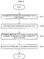
- FIG. 4 is a flowchart describing a motion of the second embodiment. Configurations which are the same as or similar to those in FIG. 1 will be described by using the same reference signs.
- the robot control device 16 transmits motion information of the robot device to a robot motion recognition part 18 in the control device 5
- the robot motion recognition part 18 acquires position and motion information of the robot device (S101).
- a condition of a cleaning fluid pressure stored in a storage device 20 is read (S102).
- a cleaning fluid pressure determination part 19 determines the pressure of the cleaning fluid based on the motion information of the robot device acquired in S101 (S103).
- the cleaning fluid pressure determination part 19 commands a cleaning fluid pressure adjusting device 14 to adjust the fluid pressure to the determined pressure (S104).
- the cleaning fluid pressure determination part 19 can command the cleaning fluid pressure adjusting device 14 to reduce the pressure of the fluid to be ejected.
- this system can prevent the machining fluid from being scattered outside the machining tank 1. Furthermore, for example, by using this system and storing the condition in the storage device 20, the workpiece table 4 can be cleaned with high-pressure fluid. Thus, the pressure of the machining fluid to be ejected from the cleaning device can be adjusted in accordance with the place to be cleaned by the robot device.
- the inside of the machining tank 1 is not formed to have a simple box shape. Rather, many obstacles to the operation of the robot device are arranged in the machining tank, including the workpiece table 4 and the electrode supporting parts 2, 3. Therefore, if the robot device alone is moved for the operation, some places are difficult to clean and others are not able to be cleaned. Furthermore, the cleaning operation might not be performed efficiently. In order to solve these problems, it is necessary to move the positions of the electrode supporting parts 2, 3 and the machining tank in accordance with the motion of the robot device and the place to be cleaned when the robot device performs the cleaning operation.
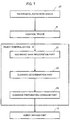
- FIG. 5 is a functional block diagram of control according to the third embodiment of the present invention.
- FIG. 6 is a flowchart describing a motion of the third embodiment.
- the robot control device 16 transmits the motion information of the robot device to the robot motion recognition part 18 in the control device 5, the robot motion recognition part 18 acquires the position and motion information of the robot device (S105).
- Position information of the position driving parts 6, 7, 8, 9, 10 of the electric discharge machine is obtained from the control device 5, whereby a position determination part 21 acquires position coordinates of the electrode supporting parts 2, 3 (S106).
- a condition of a positional relationship between the robot device and the electrode supporting parts 2, 3 stored in the storage device 20 is read (S107).
- the position determination part 21 determines the positions of the electrode supporting parts 2, 3 based on the acquired position and motion information of the robot device and the condition of the position and the positional relationship of the electrode supporting parts (S108).
- a result determined by the position determination part 21 is transmitted to the position driving parts 6, 7, 8, 9 for controlling the electrode supporting parts 2, 3 to be positioned in the determined positions (S109).
- the condition that the upper electrode supporting part should be moved upward when cleaning the workpiece table is input to the storage device 20 of the control device 5.
- the robot motion recognition part 18 recognizes that the robot control device 16 gives a command to clean the workpiece table 4
- the position driving part 10 can be commanded to move the upper electrode supporting part 2 upward.
- the above-mentioned effect is not limited to the upper electrode supporting part 2 exemplified above.
- the driving parts 6, 7 can move to create a space for enabling free movement of the robot device by inputting the condition to the storage device 20.
- the positions of the electrode supporting parts 2, 3 and the machining tank can be moved in accordance with the motion of the robot device and the place to be cleaned when the robot device performs the cleaning operation, whereby the automatic cleaning operation can be performed efficiently.
- the robot device performs the cleaning operation while the machining fluid is still stored in the machining tank 1, the robot device will be immersed in the machining fluid, thereby causing machine trouble. Therefore, there is a need for a function to determine whether the machining fluid is stored in the machining tank before the robot device executes the automatic cleaning operation and, when stored, to command the control device to discharge the machining fluid.
- FIG. 7 is a functional block diagram of control according to the fourth embodiment of the present invention.
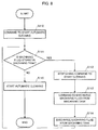
- FIG. 8 is a flowchart describing a motion of the fourth embodiment.
- a machining tank recognition part 22 arranged in the robot control device receives, from the control device 5, water level information of the machining fluid in the machining tank obtained from a water level detection device 17 in the electric discharge machine so as to determine whether the machining fluid is stored in the machining tank (S111).
- the automatic cleaning is started accordingly (S115).
- a cleaning determination part 23 stops the robot control device 16 from giving a command to start the cleaning (S112).
- a cleaning preparation command part 24 commands the control device 5 to discharge the machining fluid from the machining tank (S114). After the machining fluid is discharged from the machining tank, and the machining tank recognition part 22 determines that the machining fluid no longer exists in the machining tank, the robot control device 16 is allowed to start the automatic cleaning (S115).
- the cleaning inside the machining tank can be automated, thereby reducing a burden on the user.
Landscapes
- Engineering & Computer Science (AREA)
- Mechanical Engineering (AREA)
- Chemical & Material Sciences (AREA)
- Chemical Kinetics & Catalysis (AREA)
- Electrochemistry (AREA)
- Electrical Discharge Machining, Electrochemical Machining, And Combined Machining (AREA)
- Cleaning By Liquid Or Steam (AREA)
- Manipulator (AREA)
Abstract
Description
- The present invention relates to an electric discharge machine. Specifically, the present invention relates to an electric discharge machine having a function to clean the inside of a machining tank.
- The electric discharge machine is a machine tool for machining a workpiece by generating an electric discharge between a tool electrode and the workpiece. The tool electrode includes, for example, a wire electrode. The workpiece is machined while the workpiece is immersed in machining fluid. Alternatively, the workpiece is machined while the machining fluid is ejected to the workpiece. Therefore, electric discharge machining is performed in a machining tank.
- Machining chips are produced during the electric discharge machining. The machining chips contaminating the machining fluid stick to each part inside the machining tank. If the machining chips stuck to the machining tank are left as they are, a variety of accuracy deterioration and machine trouble may be caused. For example, the machining chips fixed to a workpiece table may deteriorate fixing accuracy of the workpiece. Furthermore, the machining chips fixed to a sealing part of the machining tank may increase a load on the sealing part, or cause water leakage. Therefore, a cleaning operation inside the machining tank is essential for using the electric discharge machine continuously.
-
JP 2009-255223 A - Conventionally, the inside of the machining tank is cleaned by using a cleaning device, in which the machining fluid is pumped by a pump from a machining fluid tank provided in the electric discharge machine so that the machining fluid is ejected from a cleaning gun. A user of the electric discharge machine operates the cleaning gun to eject the machining fluid, by which contamination due to, for example, the machining chips stuck to each part inside the machining tank is cleaned off, thereby preventing the machine trouble and the accuracy deterioration caused by the contamination in the machining tank.
- However, this cleaning operation always requires manual labor, thereby imposing a burden on the user. Although the electric discharge machining has been automated in recent years, as long as the cleaning inside the machining tank requires the manual labor, automatic machining cannot be performed continuously. Therefore, one of the problems in automating the electric discharge machining is to automate the cleaning operation of the electric discharge machine. Thus, if the cleaning operation inside the machining tank can be automated, the burden on an operator will be reduced, thereby enhancing the automation of the electric discharge machining.
- In consideration of these problems, an object of the present invention is to provide an electric discharge machine employing an automated cleaning operation by having a robot system for cleaning the inside of a machining tank. The robot system is synchronized with the electric discharge machine.
- An electric discharge machine according to an embodiment of the present invention machines a workpiece by immersing the workpiece in machining fluid or by ejecting the machining fluid to the workpiece, the electric discharge machine including: a cleaning device configured to inject the machining fluid or cleaning fluid; a robot device configured to move an injection nozzle of the cleaning device; a robot control device configured to control the robot device; and a control device configured to control the cleaning device.
- The control device may include a robot motion recognition part configured to acquire and recognize motion or position information of the robot device from the robot control device; a storage device configured to store a pressure condition or a flow rate condition of the machining fluid or the cleaning fluid corresponding to the motion or position information of the robot device; a cleaning fluid pressure determination part configured to determine a pressure or a flow rate of the machining fluid or the cleaning fluid based on the motion or position information of the robot device, and on the condition stored in the storage device; and a cleaning fluid pressure adjusting device configured to adjust the cleaning fluid, to be injected by the cleaning device, to the pressure or the flow rate of the machining fluid or the cleaning fluid determined by the cleaning fluid pressure determination part, and the control device may adjust the pressure or the flow rate of the cleaning fluid in accordance with a place to be cleaned.
- The control device may include a position driving part capable of driving a position of an electrode supporting part that supports an electrode configured to perform electric discharge machining; a robot motion recognition part; a storage device configured to store a position condition of the electrode supporting part corresponding to a motion of the robot device; and a position determination part configured to determine the position of the electrode supporting part based on the motion information of the robot device obtained from the robot motion recognition part, and on the condition read from the storage device, the position determination part being provided in the control device configured to control the position driving part, and the control device may be synchronized with the motion of the robot device so as to move a machining tank or the electrode supporting part.
- The robot control device may include a machining tank recognition part configured to recognize a state inside the machining tank from information obtained from a water level detection device configured to detect a water level of the machining fluid inside the machining tank; a cleaning determination part configured to determine whether automatic cleaning is to be started based on information obtained from the machining tank recognition part; and a cleaning preparation command part configured to command the control device to discharge the machining fluid from the machining tank based on a content determined by the cleaning determination part, and the robot control device may determine whether the machining fluid is stored in the machining tank before an automatic cleaning operation is started, and when stored, the automatic cleaning is performed after discharging the machining fluid.
- The present invention including the above-mentioned configuration has a robot system synchronized with the electric discharge machine for cleaning the inside of the machining tank. Therefore, the present invention can provide the electric discharge machine employing the automated cleaning operation.
- The above-mentioned and other objects and characteristics of the present invention will be clarified by the following description of examples with reference to the accompanying drawings, wherein:
-
FIG. 1 is a view illustrating an electric discharge machine having a cleaning system by a robot; -
FIG. 2 is a view illustrating an exemplary embodiment of a robot device equipped with an injection nozzle of a cleaning device; -
FIG. 3 is a block diagram of the electric discharge machine having the cleaning system by the robot; -
FIG. 4 is a flowchart illustrating a control flow in the electric discharge machine having the cleaning system by the robot; -
FIG. 5 is a functional block diagram of control in the electric discharge machine having the cleaning system by the robot; -
FIG. 6 is a flowchart describing a motion of an example; -
FIG. 7 is a functional block diagram of control; and -
FIG. 8 is a flowchart describing a motion of an example. -
FIG. 1 is a view illustrating an electric discharge machine according to an embodiment of the present invention.FIG. 2 is a view illustrating an exemplary embodiment of a robot device equipped with an injection nozzle of a cleaning device.FIG. 1 is the view illustrating the electric discharge machine having a cleaning system by a robot. Although a wire electric discharge machine is exemplified in the first embodiment, this embodiment is applicable to any machining device as long as it is an electric discharge machine. The same shall apply to the other embodiments. - The electric discharge machine includes a machining tank 1 for immersing a workpiece in machining fluid. The machining tank 1 is provided with
electrode supporting parts electrode supporting parts Position driving parts control device 5 with position control. Theposition driving parts - The
position driving part 6 is a Y-axis driving part, which moves the machining tank 1 in a direction parallel and lateral to a paper surface together with an X-axis driving part. Theposition driving part 7 is the X-axis driving part, which moves the machining tank 1 in a direction vertical to the paper surface. Theposition driving part 8 is a V-axis driving part, which moves the upperelectrode supporting part 2 in a direction parallel to a Y-axis together with a U-axis driving part and a Z-axis driving part. Theposition driving part 9 is the U-axis driving part, which moves the upperelectrode supporting part 2 in a direction parallel to an X-axis together with the Z-axis driving part. Theposition driving part 10 is the Z-axis driving part, which moves the upperelectrode supporting part 2 in a direction parallel and longitudinal to the paper surface. - A cleaning device is a device to pump the machining fluid by a
pump 12 from atank 11 in which the machining fluid is stored. The cleaning device then ejects the machining fluid from a cleaningfluid injection nozzle 13. The ejection can be controlled by controlling thepump 12 with thecontrol device 5. Instead of the machining fluid, fluid having a higher cleaning effect may be used as cleaning fluid. - The robot device includes a
robot driving part 15. A robot arm can be operated freely by driving therobot driving part 15. A motion of the robot device is controlled by arobot control device 16 giving a position command to therobot driving part 15. The robot device may include the cleaningfluid injection nozzle 13 of the cleaning device. -
FIG. 2 is the view illustrating the exemplary embodiment of the robot device equipped with the injection nozzle of the cleaning device. - As illustrated in
FIG. 2 , a distal end of the robot device includes arobot hand 25 for attaching the cleaningfluid injection nozzle 13. When therobot control device 16 gives a command, a position and a direction of the cleaningfluid injection nozzle 13 can be moved. - As a result, the controlled robot device can freely move the cleaning
fluid injection nozzle 13 so as to eject the machining fluid into the machining tank 1. Therefore, a cleaning operation inside the machining tank 1 can be automated. - The machining fluid ejected from the cleaning device might cause problems if the cleaning operation is performed without adjusting a pressure of the machining fluid. For example, when cleaning an upper part of the machining tank 1, the machining fluid with a high pressure might be scattered outside the machining tank 1. In addition, when cleaning the workpiece table 4, the machining fluid with too low a pressure might not remove contamination. In order to solve these problems, there is a need for a function to adjust the pressure of the cleaning fluid appropriately in accordance with a place to be cleaned.
- In this regard, the second embodiment of the present invention will be described with reference to
FIGS. 1 ,3 , and4 .FIG. 3 is a functional block diagram of control according to the second embodiment of the present invention.FIG. 4 is a flowchart describing a motion of the second embodiment. Configurations which are the same as or similar to those inFIG. 1 will be described by using the same reference signs. - When the
robot control device 16 transmits motion information of the robot device to a robotmotion recognition part 18 in thecontrol device 5, the robotmotion recognition part 18 acquires position and motion information of the robot device (S101). A condition of a cleaning fluid pressure stored in astorage device 20 is read (S102). Then, a cleaning fluidpressure determination part 19 determines the pressure of the cleaning fluid based on the motion information of the robot device acquired in S101 (S103). The cleaning fluidpressure determination part 19 commands a cleaning fluidpressure adjusting device 14 to adjust the fluid pressure to the determined pressure (S104). - As a result, in order to prevent the cleaning fluid from being scattered outside the machining tank 1, for example, when a cleaning fluid ejection position exceeds a predetermined height of the machining tank 1, the cleaning fluid
pressure determination part 19 can command the cleaning fluidpressure adjusting device 14 to reduce the pressure of the fluid to be ejected. - Therefore, as already mentioned, this system can prevent the machining fluid from being scattered outside the machining tank 1. Furthermore, for example, by using this system and storing the condition in the
storage device 20, the workpiece table 4 can be cleaned with high-pressure fluid. Thus, the pressure of the machining fluid to be ejected from the cleaning device can be adjusted in accordance with the place to be cleaned by the robot device. - The inside of the machining tank 1 is not formed to have a simple box shape. Rather, many obstacles to the operation of the robot device are arranged in the machining tank, including the workpiece table 4 and the
electrode supporting parts electrode supporting parts - For the purpose of the explanation, reference is made to
FIGS. 1 ,5 , and6 . Configurations which are the same as or similar to those inFIGS. 1 and3 will be described by using the same reference signs.FIG. 5 is a functional block diagram of control according to the third embodiment of the present invention. -
FIG. 6 is a flowchart describing a motion of the third embodiment. When therobot control device 16 transmits the motion information of the robot device to the robotmotion recognition part 18 in thecontrol device 5, the robotmotion recognition part 18 acquires the position and motion information of the robot device (S105). Position information of theposition driving parts control device 5, whereby aposition determination part 21 acquires position coordinates of theelectrode supporting parts 2, 3 (S106). - A condition of a positional relationship between the robot device and the
electrode supporting parts storage device 20 is read (S107). Theposition determination part 21 determines the positions of theelectrode supporting parts position determination part 21 is transmitted to theposition driving parts electrode supporting parts - For example, in a case where the upper
electrode supporting part 2 disturbs the cleaning of the workpiece table 4, the condition that the upper electrode supporting part should be moved upward when cleaning the workpiece table is input to thestorage device 20 of thecontrol device 5. As a result, when the robotmotion recognition part 18 recognizes that therobot control device 16 gives a command to clean the workpiece table 4, theposition driving part 10 can be commanded to move the upperelectrode supporting part 2 upward. - The above-mentioned effect is not limited to the upper
electrode supporting part 2 exemplified above. When a gap between the workpiece table 4 and the lowerelectrode supporting part 3 is narrow, the drivingparts storage device 20. Thus, the positions of theelectrode supporting parts - If the robot device performs the cleaning operation while the machining fluid is still stored in the machining tank 1, the robot device will be immersed in the machining fluid, thereby causing machine trouble. Therefore, there is a need for a function to determine whether the machining fluid is stored in the machining tank before the robot device executes the automatic cleaning operation and, when stored, to command the control device to discharge the machining fluid.
- The fourth embodiment of the present invention will be described with reference to
FIGS. 1 ,7 , and8 . Configurations which are the same as or similar to those inFIGS. 1 ,3 , and5 will be described by using the same reference signs.FIG. 7 is a functional block diagram of control according to the fourth embodiment of the present invention.FIG. 8 is a flowchart describing a motion of the fourth embodiment. - When the robot device is commanded to start the automatic cleaning (S110), a machining
tank recognition part 22 arranged in the robot control device receives, from thecontrol device 5, water level information of the machining fluid in the machining tank obtained from a waterlevel detection device 17 in the electric discharge machine so as to determine whether the machining fluid is stored in the machining tank (S111). When the machiningtank recognition part 22 determines that the machining fluid is not stored in the machining tank, the automatic cleaning is started accordingly (S115). When the machining fluid is stored, acleaning determination part 23 stops therobot control device 16 from giving a command to start the cleaning (S112). After thecleaning determination part 23 temporarily stops starting the cleaning, a cleaningpreparation command part 24 commands thecontrol device 5 to discharge the machining fluid from the machining tank (S114). After the machining fluid is discharged from the machining tank, and the machiningtank recognition part 22 determines that the machining fluid no longer exists in the machining tank, therobot control device 16 is allowed to start the automatic cleaning (S115). - By utilizing this system, even if a cleaning command is transmitted to the
robot control device 16 while the machining fluid is still stored in the machining tank 1, it can be determined before therobot control device 16 performs the automatic cleaning operation whether the machining fluid is stored in the machining tank, and when stored, thecontrol device 5 of the electric discharge machine can be commanded to discharge the machining fluid. - As mentioned above, by having the cleaning system of the robot device according to an embodiment of the present invention, the cleaning inside the machining tank can be automated, thereby reducing a burden on the user.
Claims (4)
- An electric discharge machine that machines a workpiece by immersing the workpiece in machining fluid or by ejecting the machining fluid to the workpiece, the electric discharge machine comprising:a cleaning device configured to inject the machining fluid or cleaning fluid;a robot device configured to move an injection nozzle of the cleaning device;a robot control device configured to control the robot device; anda control device configured to control the cleaning device.
- The electric discharge machine according to claim 1, wherein the control device comprises:a robot motion recognition part configured to acquire and recognize motion or position information of the robot device from the robot control device;a storage device configured to store a pressure condition or a flow rate condition of the machining fluid or the cleaning fluid corresponding to the motion or position information of the robot device;a cleaning fluid pressure determination part configured to determine a pressure or a flow rate of the machining fluid or the cleaning fluid based on the motion or position information of the robot device, and on the condition stored in the storage device; anda cleaning fluid pressure adjusting device configured to adjust the cleaning fluid, to be injected by the cleaning device, to the pressure or the flow rate of the machining fluid or the cleaning fluid determined by the cleaning fluid pressure determination part, andthe control device adjusts the pressure or the flow rate of the cleaning fluid in accordance with a place to be cleaned.
- The electric discharge machine according to claim 1, wherein the control device comprises:a position driving part capable of driving a position of an electrode supporting part that supports an electrode configured to perform electric discharge machining;a robot motion recognition part configured to acquire and recognize motion or position information of the robot device from the robot control device;a storage device configured to store a position condition of the electrode supporting part corresponding to a motion of the robot device; anda position determination part configured to determine the position of the electrode supporting part based on the motion information of the robot device obtained from the robot motion recognition part, and on the condition read from the storage device, the position determination part being provided in the control device configured to control the position driving part, andthe control device is synchronized with the motion of the robot device so as to move a machining tank or the electrode supporting part.
- The electric discharge machine according to claim 1, wherein the robot control device comprises:a machining tank recognition part configured to recognize a state inside the machining tank from information obtained from a water level detection device configured to detect a water level of the machining fluid inside the machining tank;a cleaning determination part configured to determinewhether automatic cleaning is to be started based on information obtained from the machining tank recognition part; anda cleaning preparation command part configured to command the control device to discharge the machining fluid from the machining tank based on a content determined by the cleaning determination part, andthe robot control device determines whether the machining fluid is stored in the machining tank before an automatic cleaning operation is started, and when stored, the automatic cleaning is performed after discharging the machining fluid.
Applications Claiming Priority (1)
| Application Number | Priority Date | Filing Date | Title |
|---|---|---|---|
| JP2014253456A JP5960236B2 (en) | 2014-12-15 | 2014-12-15 | EDM with robotic cleaning system |
Publications (1)
| Publication Number | Publication Date |
|---|---|
| EP3034222A1 true EP3034222A1 (en) | 2016-06-22 |
Family
ID=55022283
Family Applications (1)
| Application Number | Title | Priority Date | Filing Date |
|---|---|---|---|
| EP15200065.9A Withdrawn EP3034222A1 (en) | 2014-12-15 | 2015-12-15 | Electric discharge machine |
Country Status (5)
| Country | Link |
|---|---|
| US (1) | US20160167147A1 (en) |
| EP (1) | EP3034222A1 (en) |
| JP (1) | JP5960236B2 (en) |
| KR (1) | KR101777476B1 (en) |
| CN (1) | CN105689828A (en) |
Families Citing this family (5)
| Publication number | Priority date | Publication date | Assignee | Title |
|---|---|---|---|---|
| JP5870143B2 (en) * | 2014-04-03 | 2016-02-24 | ファナック株式会社 | Wire electrical discharge machine with thermal displacement compensation function for upper and lower guides |
| JP6756539B2 (en) | 2016-08-04 | 2020-09-16 | オークマ株式会社 | Machine Tools |
| CN110624881B (en) * | 2019-09-29 | 2024-06-07 | 深圳带电科技发展有限公司 | Cleaning robot system of power equipment |
| JP7481112B2 (en) * | 2019-12-26 | 2024-05-10 | ファナック株式会社 | Thermal Displacement Compensation Device |
| DE102021122584A1 (en) * | 2021-09-01 | 2023-03-02 | MTU Aero Engines AG | Production device for the electrochemical processing of a component, in particular a turbine component, method for the electrochemical processing of a component and component |
Citations (5)
| Publication number | Priority date | Publication date | Assignee | Title |
|---|---|---|---|---|
| JPS56146624A (en) * | 1980-04-17 | 1981-11-14 | Mitsubishi Electric Corp | Discharge processing device |
| JPS57189733A (en) * | 1981-05-15 | 1982-11-22 | Mitsubishi Electric Corp | Electric processing method and apparatus therefor |
| US6215268B1 (en) * | 1999-09-10 | 2001-04-10 | Hyundai Motor Company | Washing robot system for works |
| JP2004106142A (en) * | 2002-09-20 | 2004-04-08 | Mitsubishi Electric Corp | Wire electric discharge machine |
| JP2009255223A (en) | 2008-04-16 | 2009-11-05 | Sodick Co Ltd | Composite processing device |
Family Cites Families (10)
| Publication number | Priority date | Publication date | Assignee | Title |
|---|---|---|---|---|
| US4520252A (en) * | 1981-07-07 | 1985-05-28 | Inoue-Japax Research Incorporated | Traveling-wire EDM method and apparatus with a cooled machining fluid |
| IT8352872V0 (en) * | 1983-01-24 | 1983-01-24 | Comau Spa | EQUIPMENT FOR THE WASHING OF WORKED PIECES |
| JPH07266137A (en) * | 1994-03-28 | 1995-10-17 | Makino Milling Mach Co Ltd | Wire electric discharge machine |
| US5542441A (en) * | 1994-08-03 | 1996-08-06 | Yieldup International | Apparatus for delivering ultra-low particle counts in semiconductor manufacturing |
| JP3177736B2 (en) * | 1997-09-17 | 2001-06-18 | 東京エレクトロン株式会社 | Processing equipment |
| JP3183637B2 (en) * | 1997-09-30 | 2001-07-09 | 株式会社オオガ | Work cleaning device using articulated robot |
| JP4153534B2 (en) * | 2006-05-30 | 2008-09-24 | ファナック株式会社 | Wire electric discharge machine |
| CN201997823U (en) * | 2011-02-17 | 2011-10-05 | 东莞盈拓科技实业有限公司 | Liquid supply device capable of switching two working liquids and electrical discharge machine |
| DE112011104927B4 (en) * | 2011-02-21 | 2017-10-26 | Mitsubishi Electric Corporation | Working tank of an electric discharge machining apparatus |
| CN103252546B (en) * | 2012-02-17 | 2016-03-30 | 昆山徕通机电科技有限公司 | Relatively-high temperature fluid zone Temp. control method and device in working groove |
-
2014
- 2014-12-15 JP JP2014253456A patent/JP5960236B2/en not_active Expired - Fee Related
-
2015
- 2015-12-08 KR KR1020150174113A patent/KR101777476B1/en active Active
- 2015-12-14 US US14/967,872 patent/US20160167147A1/en not_active Abandoned
- 2015-12-15 EP EP15200065.9A patent/EP3034222A1/en not_active Withdrawn
- 2015-12-15 CN CN201510937558.7A patent/CN105689828A/en active Pending
Patent Citations (5)
| Publication number | Priority date | Publication date | Assignee | Title |
|---|---|---|---|---|
| JPS56146624A (en) * | 1980-04-17 | 1981-11-14 | Mitsubishi Electric Corp | Discharge processing device |
| JPS57189733A (en) * | 1981-05-15 | 1982-11-22 | Mitsubishi Electric Corp | Electric processing method and apparatus therefor |
| US6215268B1 (en) * | 1999-09-10 | 2001-04-10 | Hyundai Motor Company | Washing robot system for works |
| JP2004106142A (en) * | 2002-09-20 | 2004-04-08 | Mitsubishi Electric Corp | Wire electric discharge machine |
| JP2009255223A (en) | 2008-04-16 | 2009-11-05 | Sodick Co Ltd | Composite processing device |
Also Published As
| Publication number | Publication date |
|---|---|
| JP2016112644A (en) | 2016-06-23 |
| CN105689828A (en) | 2016-06-22 |
| US20160167147A1 (en) | 2016-06-16 |
| JP5960236B2 (en) | 2016-08-02 |
| KR101777476B1 (en) | 2017-09-11 |
| KR20160072789A (en) | 2016-06-23 |
Similar Documents
| Publication | Publication Date | Title |
|---|---|---|
| US20160167147A1 (en) | Electric discharge machine | |
| US20170113314A1 (en) | Tool cleaning device for machine tool | |
| CN110026813B (en) | Nozzle control device for machine tool | |
| CN106914667B (en) | Wire electric discharge machining system | |
| EP3054156A1 (en) | Pumping system | |
| KR101748936B1 (en) | Wire-cut electrical discharge machining machine in which position of liquid level of machining fluid is adjusted at time of automatic wire threading | |
| EP3002165A1 (en) | Vehicle wiper device | |
| US11465184B2 (en) | Cleaning method and cleaning apparatus | |
| JP5402668B2 (en) | Tool cleaning equipment for machine tools | |
| JP6164611B2 (en) | Electrolytic machining method, tool electrode for electrolytic machining, and electrolytic machining apparatus | |
| EP2783781A2 (en) | Wire electric discharge machine with automatic wire connecting function | |
| US20150025673A1 (en) | Machine tool including coolant apparatus | |
| JP6169635B2 (en) | Wire electrical discharge machine with the function of collecting processed products (core) | |
| JP5321404B2 (en) | Tool cleaning equipment for machine tools | |
| KR20160117257A (en) | Electrical discharge machine of which axis feeding properties are changeable | |
| EP3127644A1 (en) | Wire electric discharge machine | |
| KR101355347B1 (en) | Supply apparatus of coolant for machine tool | |
| JPH04141322A (en) | Repair method for wire electrode disconnection of wire electric discharging work device | |
| JP6438235B2 (en) | Coating apparatus and coating method | |
| JP5482219B2 (en) | Tool cleaning equipment for machine tools | |
| JP6181709B2 (en) | Machine tool controller | |
| JP3083869B2 (en) | Water and oil sculpture-type electric discharge machining method and apparatus | |
| JP6316704B2 (en) | EDM machining fluid supply device | |
| JP5971018B2 (en) | Coating nozzle, coating apparatus, and coating method | |
| JP4384545B2 (en) | Dispensing device |
Legal Events
| Date | Code | Title | Description |
|---|---|---|---|
| PUAI | Public reference made under article 153(3) epc to a published international application that has entered the european phase |
Free format text: ORIGINAL CODE: 0009012 |
|
| AK | Designated contracting states |
Kind code of ref document: A1 Designated state(s): AL AT BE BG CH CY CZ DE DK EE ES FI FR GB GR HR HU IE IS IT LI LT LU LV MC MK MT NL NO PL PT RO RS SE SI SK SM TR |
|
| AX | Request for extension of the european patent |
Extension state: BA ME |
|
| 17P | Request for examination filed |
Effective date: 20161221 |
|
| RBV | Designated contracting states (corrected) |
Designated state(s): AL AT BE BG CH CY CZ DE DK EE ES FI FR GB GR HR HU IE IS IT LI LT LU LV MC MK MT NL NO PL PT RO RS SE SI SK SM TR |
|
| STAA | Information on the status of an ep patent application or granted ep patent |
Free format text: STATUS: THE APPLICATION HAS BEEN WITHDRAWN |
|
| 18W | Application withdrawn |
Effective date: 20190417 |