EP3034160A1 - Mixing container used for reagents - Google Patents
Mixing container used for reagents Download PDFInfo
- Publication number
- EP3034160A1 EP3034160A1 EP15196473.1A EP15196473A EP3034160A1 EP 3034160 A1 EP3034160 A1 EP 3034160A1 EP 15196473 A EP15196473 A EP 15196473A EP 3034160 A1 EP3034160 A1 EP 3034160A1
- Authority
- EP
- European Patent Office
- Prior art keywords
- container
- mixing
- reagents
- sealing member
- storage chambers
- Prior art date
- Legal status (The legal status is an assumption and is not a legal conclusion. Google has not performed a legal analysis and makes no representation as to the accuracy of the status listed.)
- Granted
Links
Images




Classifications
-
- B—PERFORMING OPERATIONS; TRANSPORTING
- B01—PHYSICAL OR CHEMICAL PROCESSES OR APPARATUS IN GENERAL
- B01F—MIXING, e.g. DISSOLVING, EMULSIFYING OR DISPERSING
- B01F35/00—Accessories for mixers; Auxiliary operations or auxiliary devices; Parts or details of general application
- B01F35/71—Feed mechanisms
- B01F35/713—Feed mechanisms comprising breaking packages or parts thereof, e.g. piercing or opening sealing elements between compartments or cartridges
- B01F35/7137—Piercing, perforating or melting membranes or closures which seal the compartments
-
- B—PERFORMING OPERATIONS; TRANSPORTING
- B01—PHYSICAL OR CHEMICAL PROCESSES OR APPARATUS IN GENERAL
- B01L—CHEMICAL OR PHYSICAL LABORATORY APPARATUS FOR GENERAL USE
- B01L3/00—Containers or dishes for laboratory use, e.g. laboratory glassware; Droppers
- B01L3/52—Containers specially adapted for storing or dispensing a reagent
- B01L3/527—Containers specially adapted for storing or dispensing a reagent for a plurality of reagents
-
- B—PERFORMING OPERATIONS; TRANSPORTING
- B65—CONVEYING; PACKING; STORING; HANDLING THIN OR FILAMENTARY MATERIAL
- B65D—CONTAINERS FOR STORAGE OR TRANSPORT OF ARTICLES OR MATERIALS, e.g. BAGS, BARRELS, BOTTLES, BOXES, CANS, CARTONS, CRATES, DRUMS, JARS, TANKS, HOPPERS, FORWARDING CONTAINERS; ACCESSORIES, CLOSURES, OR FITTINGS THEREFOR; PACKAGING ELEMENTS; PACKAGES
- B65D51/00—Closures not otherwise provided for
- B65D51/24—Closures not otherwise provided for combined or co-operating with auxiliary devices for non-closing purposes
- B65D51/28—Closures not otherwise provided for combined or co-operating with auxiliary devices for non-closing purposes with auxiliary containers for additional articles or materials
- B65D51/2807—Closures not otherwise provided for combined or co-operating with auxiliary devices for non-closing purposes with auxiliary containers for additional articles or materials the closure presenting means for placing the additional articles or materials in contact with the main contents by acting on a part of the closure without removing the closure, e.g. by pushing down, pulling up, rotating or turning a part of the closure, or upon initial opening of the container
- B65D51/2814—Closures not otherwise provided for combined or co-operating with auxiliary devices for non-closing purposes with auxiliary containers for additional articles or materials the closure presenting means for placing the additional articles or materials in contact with the main contents by acting on a part of the closure without removing the closure, e.g. by pushing down, pulling up, rotating or turning a part of the closure, or upon initial opening of the container the additional article or materials being released by piercing, cutting or tearing an element enclosing it
- B65D51/2828—Closures not otherwise provided for combined or co-operating with auxiliary devices for non-closing purposes with auxiliary containers for additional articles or materials the closure presenting means for placing the additional articles or materials in contact with the main contents by acting on a part of the closure without removing the closure, e.g. by pushing down, pulling up, rotating or turning a part of the closure, or upon initial opening of the container the additional article or materials being released by piercing, cutting or tearing an element enclosing it said element being a film or a foil
- B65D51/2835—Closures not otherwise provided for combined or co-operating with auxiliary devices for non-closing purposes with auxiliary containers for additional articles or materials the closure presenting means for placing the additional articles or materials in contact with the main contents by acting on a part of the closure without removing the closure, e.g. by pushing down, pulling up, rotating or turning a part of the closure, or upon initial opening of the container the additional article or materials being released by piercing, cutting or tearing an element enclosing it said element being a film or a foil ruptured by a sharp element, e.g. a cutter or a piercer
-
- B—PERFORMING OPERATIONS; TRANSPORTING
- B01—PHYSICAL OR CHEMICAL PROCESSES OR APPARATUS IN GENERAL
- B01F—MIXING, e.g. DISSOLVING, EMULSIFYING OR DISPERSING
- B01F35/00—Accessories for mixers; Auxiliary operations or auxiliary devices; Parts or details of general application
- B01F35/71—Feed mechanisms
- B01F35/716—Feed mechanisms characterised by the relative arrangement of the containers for feeding or mixing the components
- B01F35/7163—Feed mechanisms characterised by the relative arrangement of the containers for feeding or mixing the components the containers being connected in a mouth-to-mouth, end-to-end disposition, i.e. the openings are juxtaposed before contacting the contents
-
- B—PERFORMING OPERATIONS; TRANSPORTING
- B01—PHYSICAL OR CHEMICAL PROCESSES OR APPARATUS IN GENERAL
- B01L—CHEMICAL OR PHYSICAL LABORATORY APPARATUS FOR GENERAL USE
- B01L3/00—Containers or dishes for laboratory use, e.g. laboratory glassware; Droppers
- B01L3/50—Containers for the purpose of retaining a material to be analysed, e.g. test tubes
- B01L3/502—Containers for the purpose of retaining a material to be analysed, e.g. test tubes with fluid transport, e.g. in multi-compartment structures
-
- B—PERFORMING OPERATIONS; TRANSPORTING
- B65—CONVEYING; PACKING; STORING; HANDLING THIN OR FILAMENTARY MATERIAL
- B65D—CONTAINERS FOR STORAGE OR TRANSPORT OF ARTICLES OR MATERIALS, e.g. BAGS, BARRELS, BOTTLES, BOXES, CANS, CARTONS, CRATES, DRUMS, JARS, TANKS, HOPPERS, FORWARDING CONTAINERS; ACCESSORIES, CLOSURES, OR FITTINGS THEREFOR; PACKAGING ELEMENTS; PACKAGES
- B65D23/00—Details of bottles or jars not otherwise provided for
- B65D23/04—Means for mixing or for promoting flow of contents
-
- B—PERFORMING OPERATIONS; TRANSPORTING
- B65—CONVEYING; PACKING; STORING; HANDLING THIN OR FILAMENTARY MATERIAL
- B65D—CONTAINERS FOR STORAGE OR TRANSPORT OF ARTICLES OR MATERIALS, e.g. BAGS, BARRELS, BOTTLES, BOXES, CANS, CARTONS, CRATES, DRUMS, JARS, TANKS, HOPPERS, FORWARDING CONTAINERS; ACCESSORIES, CLOSURES, OR FITTINGS THEREFOR; PACKAGING ELEMENTS; PACKAGES
- B65D81/00—Containers, packaging elements, or packages, for contents presenting particular transport or storage problems, or adapted to be used for non-packaging purposes after removal of contents
- B65D81/32—Containers, packaging elements, or packages, for contents presenting particular transport or storage problems, or adapted to be used for non-packaging purposes after removal of contents for packaging two or more different materials which must be maintained separate prior to use in admixture
- B65D81/3205—Separate rigid or semi-rigid containers joined to each other at their external surfaces
- B65D81/3211—Separate rigid or semi-rigid containers joined to each other at their external surfaces coaxially and provided with means facilitating admixture
-
- B—PERFORMING OPERATIONS; TRANSPORTING
- B01—PHYSICAL OR CHEMICAL PROCESSES OR APPARATUS IN GENERAL
- B01L—CHEMICAL OR PHYSICAL LABORATORY APPARATUS FOR GENERAL USE
- B01L2200/00—Solutions for specific problems relating to chemical or physical laboratory apparatus
- B01L2200/02—Adapting objects or devices to another
- B01L2200/025—Align devices or objects to ensure defined positions relative to each other
-
- B—PERFORMING OPERATIONS; TRANSPORTING
- B01—PHYSICAL OR CHEMICAL PROCESSES OR APPARATUS IN GENERAL
- B01L—CHEMICAL OR PHYSICAL LABORATORY APPARATUS FOR GENERAL USE
- B01L2200/00—Solutions for specific problems relating to chemical or physical laboratory apparatus
- B01L2200/06—Fluid handling related problems
- B01L2200/0689—Sealing
-
- B—PERFORMING OPERATIONS; TRANSPORTING
- B01—PHYSICAL OR CHEMICAL PROCESSES OR APPARATUS IN GENERAL
- B01L—CHEMICAL OR PHYSICAL LABORATORY APPARATUS FOR GENERAL USE
- B01L2300/00—Additional constructional details
- B01L2300/04—Closures and closing means
- B01L2300/041—Connecting closures to device or container
- B01L2300/044—Connecting closures to device or container pierceable, e.g. films, membranes
-
- B—PERFORMING OPERATIONS; TRANSPORTING
- B01—PHYSICAL OR CHEMICAL PROCESSES OR APPARATUS IN GENERAL
- B01L—CHEMICAL OR PHYSICAL LABORATORY APPARATUS FOR GENERAL USE
- B01L2300/00—Additional constructional details
- B01L2300/04—Closures and closing means
- B01L2300/046—Function or devices integrated in the closure
-
- B—PERFORMING OPERATIONS; TRANSPORTING
- B01—PHYSICAL OR CHEMICAL PROCESSES OR APPARATUS IN GENERAL
- B01L—CHEMICAL OR PHYSICAL LABORATORY APPARATUS FOR GENERAL USE
- B01L2300/00—Additional constructional details
- B01L2300/04—Closures and closing means
- B01L2300/046—Function or devices integrated in the closure
- B01L2300/047—Additional chamber, reservoir
-
- B—PERFORMING OPERATIONS; TRANSPORTING
- B01—PHYSICAL OR CHEMICAL PROCESSES OR APPARATUS IN GENERAL
- B01L—CHEMICAL OR PHYSICAL LABORATORY APPARATUS FOR GENERAL USE
- B01L2300/00—Additional constructional details
- B01L2300/06—Auxiliary integrated devices, integrated components
- B01L2300/0672—Integrated piercing tool
Definitions
- the present invention relates to a mixing container for mixing two or more reagents.
- samples include bodily fluids such as pharyngeal mucus, nasal cavity mucus, and blood.
- Non-Patent Document 1 JP H8-91418A (Patent Document 1) and " ImmunoFineTM Strep A", [online], April 2011, Nichirei Biosciences Inc., (searched on 10/14/2014), Internet ⁇ URL: http://www.nichirei.co.jp/bio/products/pdf2/522071_2.pdf> (Non-Patent Document 1)).
- Patent Document 1 and Non-Patent Document 1 disclose mixing containers provided with a tubular first container containing a first reagent and a second container containing a second reagent. Also, with both mixing containers, the second container is fit onto an opening of the first container.
- the second container is fit onto the first container with a screw structure, and furthermore includes a tubular storage tube filled with the second reagent.
- the mixing container disclosed in Patent Document 1 is configured such that when the second container is raised while being rotated, the bottom of the storage tube comes off and the second reagent falls below. For this reason, in the case of using the mixing container disclosed in Patent Document 1, the user can easily mix the reagents by merely rotating the second container.
- the second container is formed in a tube shape that can be fit inside of the first container. Furthermore, the bottom portion of the second container is also formed such that it is easily broken upon being pressed with a cotton swab on which a sample has been collected. Accordingly, in the case of using the mixing container disclosed in Non-Patent Document 1, the user can easily mix the reagents by merely inserting a cotton swab on which a sample has been collected into the second container and in that state, pressing it in.
- Patent Document 1 is problematic in its construction, in that it is difficult to remove the lid of the storage tube if the force with which it is rotated is weak. It is also problematic in that a user usually needs to perform tasks while wearing gloves, and the task of rotating the second container while wearing gloves is not easy.
- Non-Patent Document 1 is problematic in that the bottom of the second container needs to be broken with the cotton swab, and this task is not necessarily a task that is easy for everyone. It is also problematic in that, when breaking the bottom of the second container, and when removing the second container from the first container, drops of liquid are scattered, and in particular, there is a risk of infection in the case where the sample contains bacteria, a virus, or the like.
- a mixing container for mixing two or more reagents, including: a first container storing two or more reagents; and a second container for mixing the two or more reagents, wherein the first container includes: reagent storage chambers that are respectively provided for the two or more reagents and have openings formed at portions thereof; and a sealing member that seals respective openings of the reagent storage chambers, and the second container includes: an opening portion formed so that the first container can be connected thereto; and protruding portions disposed so as to pierce the sealing member when the first container is connected to the opening portion.
- the sealing container according to the present invention it is possible to improve workability for when mixing two or more reagents.
- the reagent storage chambers are formed such that the openings face an identical direction
- the opening portion is formed such that the first container can be connected thereto by fitting with the sealing member facing the second container, and the number of the protruding portions is the same as the number of the reagent storage chambers, and the protruding portions are disposed so as to face the respective corresponding storage chambers.
- the first container includes a through hole, and the through hole is formed such that an interior and exterior of the second container are in communication when the first container is connected to the second container. In this case, a sample can be easily supplied to the mixing container.
- the mixing container according to the present invention includes a nozzle that can drip a liquid and is formed to be attachable to the through hole. In this case, dripping of the mixed reagent into which the sample was extracted can be performed easily using the mixing container.
- the protruding portions are formed such that portions of the sealing member along edges of the openings of the reagent storage chambers are cut, excluding parts of the portions, when the first container is connected to the opening portion.
- the cut pieces of the sealing member can be prevented from falling together with the reagents to the bottom of the second container.
- the protruding portions each include a shearing portion and a pushing portion
- the shearing portion is formed so as to protrude more toward the sealing member than the pushing portion does
- the pushing portion is formed at a position closer to a portion of the sealing member that is not to be cut than the shearing portion is.
- FIG. 1 is an exploded perspective view showing a configuration of a mixing container according to an embodiment of the present invention.
- FIG. 2 is a perspective view showing a state in which the mixing container shown in FIG. 1 has been assembled.
- FIG. 3 is a cross-sectional view of the mixing container shown in FIG. 1 .
- a mixing container 100 according to the present embodiment which is shown in FIG. 1 , is used for mixing two or more reagents. As shown in FIG. 1 , the mixing container 100 includes a first container 10 and a second container 20.
- the first container 10 is a container that stores two or more reagents, and includes reagent storage chambers 11 respectively provided for the reagents, and a sealing member 12. Also, the reagent storage chambers 11 are formed so as to have openings formed at portions thereof. In FIG. 1 , the openings of the reagent storage chambers 11 are indicated by broken lines.
- the sealing member 12 seals the respective openings of the reagent storage chambers 11. Also, the sealing member 12 is formed of paper, resin film, metallic foil, or the like.
- the reagent storage chambers 11 are formed such that the openings face an identical direction. Also, in this case, it is possible to use a member that can seal all of the reagent storage chambers 11 collectively as the sealing member 12. Furthermore, in the example shown in FIGS. 1 and 2 , since the mixing container 100 is used for mixing two reagents, the number of reagent storage chambers 11 is also two. However, in the present embodiment, there is no particular limitation to these numbers. In the present embodiment, it is sufficient that the number of reagent storage chambers 11 is two or more.
- the second container 20 is a container for mixing two or more reagents, and includes an opening portion 21 that is formed so that the first container 10 can connect thereto, and protruding portions 22.
- the opening portion 21 is formed so as to be able to connect with the first container 10.
- the opening portion 21 and the first container 10 are connected by fitting the first container 10 onto the opening portion 21 with the sealing member 12 facing the second container 20.
- the protruding portions 22 are disposed so as to pierce the sealing member 12 of the first container 10 when the first container 10 is connected to the opening portion 21.
- the number of the protruding portions 22 is the same as the number of the reagent storage chambers 11, and the protruding portions 22 are disposed so as to face the respective corresponding reagent storage chambers 11.
- FIGS. 2 and 3 by merely connecting the first container 10 and the second container 20 with the sealing member 12 facing the opening portion 21 of the second container 20, the sealing member 12 is broken, and the reagents in the reagent storage chambers 11 fall to the bottom of the second container 20, where they are mixed together. Also, in the present embodiment, in order to ensure that the reagents fall, an inclined surface 25 is provided below the protruding portions 22 inside of the second container 20.
- reference numeral 30 indicates reagents that have been mixed (mixed reagent).
- the protruding portions 22 are formed such that portions of the sealing member 12 along the edges of the openings of the reagent storage chambers 11 are cut, excluding parts of the portions, when the first container 10 is connected to the opening portion 21. This is done to prevent cut pieces of the sealing member 12 from falling together with the reagents to the bottom of the second container 20.
- the openings of the reagent storage chambers 11 each have a quarter-circle shape.
- the cross-sectional shapes of the protruding portions 22 are each formed such that portions of the sealing member 12 located at an arc-shaped portion and one linear portion of each opening are cut, and portions of the sealing member 12 located at the remaining linear portion of each opening are not cut.
- the first container 10 includes a through hole 13 for supplying a sample, as will be described later.
- the through hole 13 is formed such that the interior and exterior of the second container 20 are in communication when the first container 10 is connected to the second container 20.
- the mixing container 100 includes a nozzle 23.
- the nozzle 23 is formed so as to be able to drip a liquid and be attachable to the through hole 13 of the first container 10.
- the nozzle 23 is attached to the second container 20 by a flexible belt-shaped member 24 for the sake of convenience during operation.
- the second container 20, the nozzle 23, and the belt-shaped member 24 are formed integrally by injection molding using a resin material.
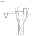
- FIG. 4 is a cross-sectional view showing a state of extracting a sample into reagents that have been mixed in the mixing container.
- FIG. 5 is a perspective view showing a state in which it is possible to drip the reagent into which a sample was extracted with the mixing container.
- the user inserts a cotton swab 31 into the mixing container 100 through the through hole 13 and immerses a leading end portion 31a on which a sample has been collected in the mixed reagent 30. According to this, a sample is extracted into the mixed reagent 30.
- the sample is supplied using a cotton swab 31, but the present embodiment is not limited to this example.
- the sample may be supplied directly through the through hole 13, for example.
- the mixing container 100 enters the state shown in FIG. 5 . Thereafter, depending on the kind of test or the like of the sample, the user can drip the mixed reagent 30 into which the sample was extracted onto a test plate, test paper, or the like from the leading end of the nozzle 23.
- sample there is no particular limitation on the sample, and examples thereof include bodily fluids such as pharyngeal mucus, nasal cavity mucus, and blood.
- bodily fluids such as pharyngeal mucus, nasal cavity mucus, and blood.
- a liquid reagent is used in the example shown in FIGS. 3 and 4 , the present embodiment is not limited thereto, and a powder or capsule reagent may be used, for example.
- reagents can be mixed by merely fitting the first container 10 and the second container 20 together. That is to say, there is no need to rotate the container as with the prior technology, and the user can easily mix reagents while wearing gloves. For this reason, with the mixing container 100, it is possible to improve workability for when mixing two or more reagents.
- the reagents are sealed in the first container 10 by the sealing member 12 from the time of manufacturing at a factory to the time of use. For this reason, with the mixing container 100, it is possible to suppress degradation in the quality of the reagents.
- FIG. 6 is a cross-sectional view showing another example of a mixing container according to an embodiment of the present invention. Note that in FIG. 6 , only the portion near the opening portion 21 of the second container 20 is shown enlarged.
- the shape of portions 22a on the opening side of the protruding portions 22 is a pointed shape. This is done so that the shearing force applied by the protruding portions 22 can be increased and the sealing member 12 (see FIG. 1 ) can be cut with less force. Also, by using this kind of shape, it is possible to further improve workability.
- the protruding portions 22 each include a shearing portion 22b and a pushing portion 22c.
- the shearing portion 22b is formed so as to protrude more toward the sealing member 12 than the pushing portion 22c does.
- the pushing portion 22c is formed at a location that is closer to the portion of the sealing member 12 that is not to be cut than the shearing portion 22b is.
- the shearing portion 22b is formed so as to be inclined with respect to the normal line of the sealing member 12.
- the pushing portion 22c is formed parallel to the surface of the sealing member 12, and has a roughly flat shape.
- the protruding portions 22 when the first container 10 and the second container 20 are connected, the protruding portions 22 first come into contact with and cut the portions of the sealing member 12 located at the openings (see FIG. 1 ) of the reagent storage chambers 11 with the shearing portions 22b. Next, when the cutting advances, with the pushing portions 22c, the protruding portions 22 can push the cut portions of the sealing member 12 up to the inner walls of the reagent storage chambers 11, causing the cut portions to come into close contact therewith. As a result, a situation in which the reagents are retained between the cut sealing member 12 and the inner walls of the reagent storage chambers 11 is avoided. That is to say, with the present example, such a situation is avoided, and therefore the reagents can be mixed reliably and accurately.
- the mixing container according to the present invention it is possible to improve workability for when mixing two or more reagents.
- the mixing container according to the present invention is effective for use in a field in which mixing of two or more reagents is required, for example, testing of a bodily fluid collected from a human body, or the like.
Landscapes
- Chemical & Material Sciences (AREA)
- Chemical Kinetics & Catalysis (AREA)
- Health & Medical Sciences (AREA)
- Clinical Laboratory Science (AREA)
- Engineering & Computer Science (AREA)
- Mechanical Engineering (AREA)
- Analytical Chemistry (AREA)
- General Health & Medical Sciences (AREA)
- Hematology (AREA)
- Medicinal Chemistry (AREA)
- Package Specialized In Special Use (AREA)
- Agricultural Chemicals And Associated Chemicals (AREA)
Abstract
Description
- This application is based upon and claims the benefit of priority from
Japanese patent application No. 2014-255152, filed on December 17, 2014 - The present invention relates to a mixing container for mixing two or more reagents.
- Conventionally, when testing a specific sample, there are cases where preparation is needed in which two or more liquid or solid reagents are mixed immediately before use. Also, examples of samples include bodily fluids such as pharyngeal mucus, nasal cavity mucus, and blood. Also, when performing this kind of test, a special container is used in order to make it easier to mix the two or more reagents (e.g., see
JP H8-91418A - Specifically, Patent Document 1 and Non-Patent Document 1 disclose mixing containers provided with a tubular first container containing a first reagent and a second container containing a second reagent. Also, with both mixing containers, the second container is fit onto an opening of the first container.
- Out of these, with the mixing container disclosed in Patent Document 1, the second container is fit onto the first container with a screw structure, and furthermore includes a tubular storage tube filled with the second reagent. Also, the mixing container disclosed in Patent Document 1 is configured such that when the second container is raised while being rotated, the bottom of the storage tube comes off and the second reagent falls below. For this reason, in the case of using the mixing container disclosed in Patent Document 1, the user can easily mix the reagents by merely rotating the second container.
- Also, with the mixing container disclosed in Non-Patent Document 1, the second container is formed in a tube shape that can be fit inside of the first container. Furthermore, the bottom portion of the second container is also formed such that it is easily broken upon being pressed with a cotton swab on which a sample has been collected. Accordingly, in the case of using the mixing container disclosed in Non-Patent Document 1, the user can easily mix the reagents by merely inserting a cotton swab on which a sample has been collected into the second container and in that state, pressing it in.
- However, the mixing container disclosed in Patent Document 1 is problematic in its construction, in that it is difficult to remove the lid of the storage tube if the force with which it is rotated is weak. It is also problematic in that a user usually needs to perform tasks while wearing gloves, and the task of rotating the second container while wearing gloves is not easy.
- Furthermore, the mixing container disclosed in Non-Patent Document 1 is problematic in that the bottom of the second container needs to be broken with the cotton swab, and this task is not necessarily a task that is easy for everyone. It is also problematic in that, when breaking the bottom of the second container, and when removing the second container from the first container, drops of liquid are scattered, and in particular, there is a risk of infection in the case where the sample contains bacteria, a virus, or the like.
- It is an object of the present invention to provide a mixing container according to which it is possible to improve workability for when mixing two or more reagents.
- In order to achieve the foregoing object, a mixing container according to the present invention is a mixing container for mixing two or more reagents, including: a first container storing two or more reagents; and a second container for mixing the two or more reagents, wherein the first container includes: reagent storage chambers that are respectively provided for the two or more reagents and have openings formed at portions thereof; and a sealing member that seals respective openings of the reagent storage chambers, and the second container includes: an opening portion formed so that the first container can be connected thereto; and protruding portions disposed so as to pierce the sealing member when the first container is connected to the opening portion.
- According to the foregoing characteristics, by merely connecting the first container and the second container, the seal of the reagent storage chambers can be broken and the reagents can be mixed easily. With the mixing container according to the present invention, it is possible to improve workability for when mixing two or more reagents.
- With the mixing container according to the present invention, it is preferable that in the first container, the reagent storage chambers are formed such that the openings face an identical direction, and in the second container, the opening portion is formed such that the first container can be connected thereto by fitting with the sealing member facing the second container, and the number of the protruding portions is the same as the number of the reagent storage chambers, and the protruding portions are disposed so as to face the respective corresponding storage chambers. In this case, since the seal of the reagent storage chambers can be broken with less force, workability can be improved even further.
- Also, with the mixing container according to the present invention, it is preferable that the first container includes a through hole, and the through hole is formed such that an interior and exterior of the second container are in communication when the first container is connected to the second container. In this case, a sample can be easily supplied to the mixing container.
- In addition, if the through hole is provided, it is further preferable that the mixing container according to the present invention includes a nozzle that can drip a liquid and is formed to be attachable to the through hole. In this case, dripping of the mixed reagent into which the sample was extracted can be performed easily using the mixing container.
- Also, with the mixing container according to the present invention, it is preferable that in the second container, the protruding portions are formed such that portions of the sealing member along edges of the openings of the reagent storage chambers are cut, excluding parts of the portions, when the first container is connected to the opening portion. In this case, the cut pieces of the sealing member can be prevented from falling together with the reagents to the bottom of the second container.
- Furthermore, in the above-described case, it is preferable that the protruding portions each include a shearing portion and a pushing portion, the shearing portion is formed so as to protrude more toward the sealing member than the pushing portion does, and the pushing portion is formed at a position closer to a portion of the sealing member that is not to be cut than the shearing portion is. According to this aspect, the cut portions of the sealing member are pushed up to the inner walls of the reagent storage chambers, and come into close contact therewith. As a result, a situation in which the reagents are retained between the cut sealing member and the inner walls of the reagent storage chambers is avoided, and it is easy to reliably and accurately mix the reagents.
- With the mixing container according to the present invention, it is possible to improve workability for when mixing two or more reagents.
- The foregoing and other objects, features, aspects and advantages of the present invention will become more apparent from the following detailed description of the present invention when taken in conjunction with the accompanying drawings.
-
-
FIG. 1 is an exploded perspective view showing a configuration of a mixing container according to an embodiment of the present invention. -
FIG. 2 is a perspective view showing a state in which the mixing container shown inFIG. 1 has been assembled. -
FIG. 3 is a cross-sectional view of the mixing container shown inFIG. 1 . -
FIG. 4 is a cross-sectional view showing a state of a sample being extracted into reagents that have been mixed in the mixing container. -
FIG. 5 is a perspective view showing a state in which it is possible to drip the reagent into which a sample was extracted with the mixing container. -
FIG. 6 is a cross-sectional view showing another example of a mixing container according to an embodiment of the present invention. - Hereinafter, a mixing container according to an embodiment of the present invention will be described with reference to
FIGS. 1 to 4 . - First, a configuration of a mixing container according to the present embodiment will be described with reference to
FIGS. 1 to 3 .FIG. 1 is an exploded perspective view showing a configuration of a mixing container according to an embodiment of the present invention.FIG. 2 is a perspective view showing a state in which the mixing container shown inFIG. 1 has been assembled.FIG. 3 is a cross-sectional view of the mixing container shown inFIG. 1 . - A
mixing container 100 according to the present embodiment, which is shown inFIG. 1 , is used for mixing two or more reagents. As shown inFIG. 1 , themixing container 100 includes afirst container 10 and asecond container 20. - The
first container 10 is a container that stores two or more reagents, and includesreagent storage chambers 11 respectively provided for the reagents, and asealing member 12. Also, thereagent storage chambers 11 are formed so as to have openings formed at portions thereof. InFIG. 1 , the openings of thereagent storage chambers 11 are indicated by broken lines. The sealingmember 12 seals the respective openings of thereagent storage chambers 11. Also, the sealingmember 12 is formed of paper, resin film, metallic foil, or the like. - Also, in the present embodiment, in order to make it so that every seal of the
reagent storage chambers 11 can be broken at once, thereagent storage chambers 11 are formed such that the openings face an identical direction. Also, in this case, it is possible to use a member that can seal all of thereagent storage chambers 11 collectively as the sealingmember 12. Furthermore, in the example shown inFIGS. 1 and2 , since themixing container 100 is used for mixing two reagents, the number ofreagent storage chambers 11 is also two. However, in the present embodiment, there is no particular limitation to these numbers. In the present embodiment, it is sufficient that the number ofreagent storage chambers 11 is two or more. - Also, the
second container 20 is a container for mixing two or more reagents, and includes an openingportion 21 that is formed so that thefirst container 10 can connect thereto, and protrudingportions 22. Among these, the openingportion 21 is formed so as to be able to connect with thefirst container 10. In the present embodiment, the openingportion 21 and thefirst container 10 are connected by fitting thefirst container 10 onto the openingportion 21 with the sealingmember 12 facing thesecond container 20. - Also, the protruding
portions 22 are disposed so as to pierce the sealingmember 12 of thefirst container 10 when thefirst container 10 is connected to the openingportion 21. In the present embodiment, the number of the protrudingportions 22 is the same as the number of thereagent storage chambers 11, and the protrudingportions 22 are disposed so as to face the respective correspondingreagent storage chambers 11. - Accordingly, as shown in
FIGS. 2 and3 , by merely connecting thefirst container 10 and thesecond container 20 with the sealingmember 12 facing the openingportion 21 of thesecond container 20, the sealingmember 12 is broken, and the reagents in thereagent storage chambers 11 fall to the bottom of thesecond container 20, where they are mixed together. Also, in the present embodiment, in order to ensure that the reagents fall, aninclined surface 25 is provided below the protrudingportions 22 inside of thesecond container 20. InFIG. 3 ,reference numeral 30 indicates reagents that have been mixed (mixed reagent). - Furthermore, in the present embodiment, the protruding
portions 22 are formed such that portions of the sealingmember 12 along the edges of the openings of thereagent storage chambers 11 are cut, excluding parts of the portions, when thefirst container 10 is connected to the openingportion 21. This is done to prevent cut pieces of the sealingmember 12 from falling together with the reagents to the bottom of thesecond container 20. - Specifically, in the present embodiment, the openings of the
reagent storage chambers 11 each have a quarter-circle shape. Also, in correspondence with this, the cross-sectional shapes of the protrudingportions 22 are each formed such that portions of the sealingmember 12 located at an arc-shaped portion and one linear portion of each opening are cut, and portions of the sealingmember 12 located at the remaining linear portion of each opening are not cut. - Also, as shown in
FIGS. 1 to 3 , in the present embodiment, thefirst container 10 includes a throughhole 13 for supplying a sample, as will be described later. The throughhole 13 is formed such that the interior and exterior of thesecond container 20 are in communication when thefirst container 10 is connected to thesecond container 20. - Furthermore, in the present embodiment, the mixing
container 100 includes anozzle 23. Thenozzle 23 is formed so as to be able to drip a liquid and be attachable to the throughhole 13 of thefirst container 10. Also, thenozzle 23 is attached to thesecond container 20 by a flexible belt-shapedmember 24 for the sake of convenience during operation. Specifically, thesecond container 20, thenozzle 23, and the belt-shapedmember 24 are formed integrally by injection molding using a resin material. - Next, a method of using the mixing
container 100 will be described with reference toFIGS. 4 and5 .FIG. 4 is a cross-sectional view showing a state of extracting a sample into reagents that have been mixed in the mixing container.FIG. 5 is a perspective view showing a state in which it is possible to drip the reagent into which a sample was extracted with the mixing container. - First, as shown in
FIGS. 2 and3 , when the user fits thefirst container 10 onto the openingportion 21 of thesecond container 20 so as to connect them, the sealingmember 12 that seals the tworeagent storage chambers 11 is broken. Accordingly, the reagents fall to the bottom of thesecond container 20. Then, the user mixes the two reagents by shaking the mixingcontainer 100 or the like. - Next, as shown in
FIG. 4 , the user inserts acotton swab 31 into the mixingcontainer 100 through the throughhole 13 and immerses aleading end portion 31a on which a sample has been collected in themixed reagent 30. According to this, a sample is extracted into themixed reagent 30. Note that in the example shown inFIG. 4 , the sample is supplied using acotton swab 31, but the present embodiment is not limited to this example. The sample may be supplied directly through the throughhole 13, for example. - Next, the user takes the
cotton swab 31 out through the throughhole 13 and fits thenozzle 23 into the throughhole 13. According to this, the mixingcontainer 100 enters the state shown inFIG. 5 . Thereafter, depending on the kind of test or the like of the sample, the user can drip themixed reagent 30 into which the sample was extracted onto a test plate, test paper, or the like from the leading end of thenozzle 23. - Also, in the present embodiment, there is no particular limitation on the sample, and examples thereof include bodily fluids such as pharyngeal mucus, nasal cavity mucus, and blood. Furthermore, although a liquid reagent is used in the example shown in
FIGS. 3 and4 , the present embodiment is not limited thereto, and a powder or capsule reagent may be used, for example. - As described above, with the mixing
container 100 according to the present embodiment, reagents can be mixed by merely fitting thefirst container 10 and thesecond container 20 together. That is to say, there is no need to rotate the container as with the prior technology, and the user can easily mix reagents while wearing gloves. For this reason, with the mixingcontainer 100, it is possible to improve workability for when mixing two or more reagents. - Also, the reagents are sealed in the
first container 10 by the sealingmember 12 from the time of manufacturing at a factory to the time of use. For this reason, with the mixingcontainer 100, it is possible to suppress degradation in the quality of the reagents. - Next, another example of a mixing container according to the present embodiment will be described with reference to
FIG. 6. FIG. 6 is a cross-sectional view showing another example of a mixing container according to an embodiment of the present invention. Note that inFIG. 6 , only the portion near the openingportion 21 of thesecond container 20 is shown enlarged. - As shown in
FIG. 6 , in the present example, first, the shape ofportions 22a on the opening side of the protrudingportions 22 is a pointed shape. This is done so that the shearing force applied by the protrudingportions 22 can be increased and the sealing member 12 (seeFIG. 1 ) can be cut with less force. Also, by using this kind of shape, it is possible to further improve workability. - In addition, in the present example, the protruding
portions 22 each include ashearing portion 22b and a pushingportion 22c. Among these, theshearing portion 22b is formed so as to protrude more toward the sealingmember 12 than the pushingportion 22c does. Also, the pushingportion 22c is formed at a location that is closer to the portion of the sealingmember 12 that is not to be cut than theshearing portion 22b is. In other words, theshearing portion 22b is formed so as to be inclined with respect to the normal line of the sealingmember 12. On the other hand, the pushingportion 22c is formed parallel to the surface of the sealingmember 12, and has a roughly flat shape. - For this reason, in the present example, when the
first container 10 and thesecond container 20 are connected, the protrudingportions 22 first come into contact with and cut the portions of the sealingmember 12 located at the openings (seeFIG. 1 ) of thereagent storage chambers 11 with theshearing portions 22b. Next, when the cutting advances, with the pushingportions 22c, the protrudingportions 22 can push the cut portions of the sealingmember 12 up to the inner walls of thereagent storage chambers 11, causing the cut portions to come into close contact therewith. As a result, a situation in which the reagents are retained between thecut sealing member 12 and the inner walls of thereagent storage chambers 11 is avoided. That is to say, with the present example, such a situation is avoided, and therefore the reagents can be mixed reliably and accurately. - As described above, with the mixing container according to the present invention, it is possible to improve workability for when mixing two or more reagents. The mixing container according to the present invention is effective for use in a field in which mixing of two or more reagents is required, for example, testing of a bodily fluid collected from a human body, or the like.
- Although the present invention has been described and illustrated in detail, it is clearly understood that the same is by way of illustration and example only and is not to be taken by way of limitation, the scope of the present invention being interpreted by the terms of the appended claims.
Claims (6)
- A mixing container (100) for mixing two or more reagents, comprising:a first container (10) storing two or more reagents; and a second container (20) for mixing the two or more reagents,wherein the first container (10) includes:reagent storage chambers (11) that are respectively provided for the two or more reagents and have openings formed at portions thereof anda sealing member (12) that seals respective openings of the reagent storage chambers (11), andthe second container (20) includes:an opening portion (21) formed so that the first container (10) can be connected thereto; andprotruding portions (22) disposed so as to pierce the sealing member (12) when the first container (10) is connected to the opening portion (21).
- The mixing container according to claim 1, wherein
in the first container (10),
the reagent storage chambers (11) are formed such that the openings face an identical direction, and
in the second container (20),
the opening portion (21) is formed such that the first container (10) can be connected thereto by fitting with the sealing member (12) facing the second container (20), and
the number of the protruding portions (22) is the same as the number of the reagent storage chambers (11), and the protruding portions (22) are disposed so as to face the respective corresponding storage chambers (11). - The mixing container according to claim 1 or 2, wherein
the first container (10) includes a through hole (13), and
the through hole (13) is formed such that an interior and exterior of the second container (20) are in communication when the first container (10) is connected to the second container (20). - The mixing container according to claim 3, comprising
a nozzle (23) that can drip a liquid and is formed to be attachable to the through hole (13). - The mixing container according to any one of claims 1 to 4, wherein
in the second container (20),
the protruding portions (22) are formed such that portions of the sealing member (12) along edges of the openings of the reagent storage chambers (11) are cut, excluding parts of the portions, when the first container (10) is connected to the opening portion (21). - The mixing container according to claim 5, wherein
the protruding portions (22) each include a shearing portion (22b) and a pushing portion (22c),
the shearing portion (22b) is formed so as to protrude more toward the sealing member (12) than the pushing portion (22c) does, and
the pushing portion (22c) is formed at a position closer to a portion of the sealing member (12) that is not to be cut than the shearing portion (22b) is.
Applications Claiming Priority (1)
| Application Number | Priority Date | Filing Date | Title |
|---|---|---|---|
| JP2014255152A JP2016113193A (en) | 2014-12-17 | 2014-12-17 | Mixing container |
Publications (2)
| Publication Number | Publication Date |
|---|---|
| EP3034160A1 true EP3034160A1 (en) | 2016-06-22 |
| EP3034160B1 EP3034160B1 (en) | 2018-07-25 |
Family
ID=54780090
Family Applications (1)
| Application Number | Title | Priority Date | Filing Date |
|---|---|---|---|
| EP15196473.1A Active EP3034160B1 (en) | 2014-12-17 | 2015-11-26 | Mixing container used for reagents |
Country Status (5)
| Country | Link |
|---|---|
| US (1) | US10035149B2 (en) |
| EP (1) | EP3034160B1 (en) |
| JP (1) | JP2016113193A (en) |
| KR (1) | KR20160073929A (en) |
| CN (1) | CN105711953A (en) |
Cited By (1)
| Publication number | Priority date | Publication date | Assignee | Title |
|---|---|---|---|---|
| EP3311753A1 (en) * | 2016-10-19 | 2018-04-25 | Bonraybio Co., Ltd. | Collection bottle and method for detecting characteristic of sample |
Families Citing this family (3)
| Publication number | Priority date | Publication date | Assignee | Title |
|---|---|---|---|---|
| USD870312S1 (en) * | 2017-07-21 | 2019-12-17 | Tauns Laboratories, Inc. | Container for mixing reagents |
| WO2019159111A1 (en) * | 2018-02-15 | 2019-08-22 | Societe Des Produits Nestle S.A. | Assay cuvette |
| AU2019467751B2 (en) * | 2019-09-23 | 2025-09-04 | Cepheid | Multi-chambered lid apparatus with reagent port |
Citations (5)
| Publication number | Priority date | Publication date | Assignee | Title |
|---|---|---|---|---|
| JPH0891418A (en) | 1994-09-28 | 1996-04-09 | Yoshino Kogyosho Co Ltd | Two-agent-mixing container |
| US20040200742A1 (en) * | 2003-04-12 | 2004-10-14 | Cho Young Kook | Cap device for mixing different kinds of materials separately contained therein and in bottle |
| WO2005049207A1 (en) * | 2003-11-19 | 2005-06-02 | Michael O'donovan | A reagent cuvette |
| WO2006048866A1 (en) * | 2004-10-31 | 2006-05-11 | Guy Zimmerman | Beverage mixing and dispensing device |
| WO2010020043A1 (en) * | 2008-08-21 | 2010-02-25 | Dna Genotek Inc. | Sample receiving device |
Family Cites Families (11)
| Publication number | Priority date | Publication date | Assignee | Title |
|---|---|---|---|---|
| US4859603A (en) * | 1987-01-05 | 1989-08-22 | Dole Associates, Inc. | Personal diagnostic kit |
| JPH0634275Y2 (en) * | 1988-02-24 | 1994-09-07 | 株式会社吉野工業所 | Mixing container |
| JPH03126880U (en) * | 1990-03-30 | 1991-12-20 | ||
| WO2001011374A2 (en) * | 1999-08-06 | 2001-02-15 | Thermo Biostar, Inc. | An automated point of care detection system including complete sample processing capabilities |
| US20090084792A1 (en) * | 2007-10-02 | 2009-04-02 | Huang Mu-Yuan | Container Cap with Airtight Device |
| KR100840387B1 (en) * | 2007-10-31 | 2008-06-23 | 장호석 | Container |
| JP5246762B2 (en) * | 2008-09-30 | 2013-07-24 | 株式会社ミルボン | Mixing container |
| CN201541982U (en) * | 2009-12-07 | 2010-08-11 | 天津工业大学 | Storage folding cup |
| EP2633911B1 (en) * | 2012-02-28 | 2016-09-14 | ARKRAY, Inc. | Mixing apparatus |
| JP5893973B2 (en) * | 2012-03-19 | 2016-03-23 | 日本クロージャー株式会社 | cartridge |
| KR101376289B1 (en) * | 2012-11-28 | 2014-03-20 | 한동헌 | Kit for making mixture berverage |
-
2014
- 2014-12-17 JP JP2014255152A patent/JP2016113193A/en active Pending
-
2015
- 2015-11-26 EP EP15196473.1A patent/EP3034160B1/en active Active
- 2015-12-14 US US14/967,788 patent/US10035149B2/en active Active
- 2015-12-14 CN CN201510922737.3A patent/CN105711953A/en active Pending
- 2015-12-16 KR KR1020150180201A patent/KR20160073929A/en not_active Ceased
Patent Citations (5)
| Publication number | Priority date | Publication date | Assignee | Title |
|---|---|---|---|---|
| JPH0891418A (en) | 1994-09-28 | 1996-04-09 | Yoshino Kogyosho Co Ltd | Two-agent-mixing container |
| US20040200742A1 (en) * | 2003-04-12 | 2004-10-14 | Cho Young Kook | Cap device for mixing different kinds of materials separately contained therein and in bottle |
| WO2005049207A1 (en) * | 2003-11-19 | 2005-06-02 | Michael O'donovan | A reagent cuvette |
| WO2006048866A1 (en) * | 2004-10-31 | 2006-05-11 | Guy Zimmerman | Beverage mixing and dispensing device |
| WO2010020043A1 (en) * | 2008-08-21 | 2010-02-25 | Dna Genotek Inc. | Sample receiving device |
Non-Patent Citations (1)
| Title |
|---|
| "ImmunoFineTM Strep A", April 2011, NICHIREI BIOSCIENCES INC. |
Cited By (3)
| Publication number | Priority date | Publication date | Assignee | Title |
|---|---|---|---|---|
| EP3311753A1 (en) * | 2016-10-19 | 2018-04-25 | Bonraybio Co., Ltd. | Collection bottle and method for detecting characteristic of sample |
| CN107966327A (en) * | 2016-10-19 | 2018-04-27 | 邦睿生技股份有限公司 | Collection bottle and method for testing sample properties |
| US10940479B2 (en) | 2016-10-19 | 2021-03-09 | Bonraybio Co., Ltd. | Collection bottle and method for detecting characteristic of sample |
Also Published As
| Publication number | Publication date |
|---|---|
| CN105711953A (en) | 2016-06-29 |
| US10035149B2 (en) | 2018-07-31 |
| US20160175841A1 (en) | 2016-06-23 |
| EP3034160B1 (en) | 2018-07-25 |
| KR20160073929A (en) | 2016-06-27 |
| JP2016113193A (en) | 2016-06-23 |
Similar Documents
| Publication | Publication Date | Title |
|---|---|---|
| EP3034160B1 (en) | Mixing container used for reagents | |
| US9579686B2 (en) | Fluid dispensing assemblies and methods of dispensing fluids from containers | |
| EP2690424B1 (en) | Integrated collecting and dispensing device | |
| EP2214561B1 (en) | Tissue container for molecular and histology diagnostics incorporating a breakable membrane | |
| CN103459036B (en) | For the lid of airtight container | |
| US20170350838A1 (en) | Electric measuring cartridge, biological sample electric measuring device, and biological sample electric measuring method | |
| US10512908B2 (en) | Method for preparing a sample | |
| US10537892B2 (en) | Sample tube with integrated mixing plunger head | |
| WO2015104785A1 (en) | Cartridge, kit comprising cartridge, electric measuring apparatus, and electric measuring method | |
| US20210080356A1 (en) | Device for surface sampling | |
| CN109152997A (en) | System and method for multi-chamber sampler | |
| JP6021681B2 (en) | Closing means with bulkhead strip | |
| WO2017051448A1 (en) | Biopsy specimen container | |
| US20200170626A1 (en) | Device for preparing a sample to be analyzed and method for preparing a sample to be analyzed | |
| US20220373549A1 (en) | Systems and methods for an integrated consumable for analyte testing, including a premix apparatus | |
| EP2737872A1 (en) | Dental container | |
| NL2014739B1 (en) | Fluid collection device. | |
| KR101411459B1 (en) | Tube for fecal occult blood test | |
| JP4314210B2 (en) | container | |
| US20140223994A1 (en) | Direct Sampling Device for Contamination-Free Transfer of Analyte | |
| JP6015999B1 (en) | Mixing container, mixing container with contents, and method for manufacturing mixing container with contents | |
| WO2018155145A1 (en) | Blood coagulation measurement cartridge |
Legal Events
| Date | Code | Title | Description |
|---|---|---|---|
| PUAI | Public reference made under article 153(3) epc to a published international application that has entered the european phase |
Free format text: ORIGINAL CODE: 0009012 |
|
| AK | Designated contracting states |
Kind code of ref document: A1 Designated state(s): AL AT BE BG CH CY CZ DE DK EE ES FI FR GB GR HR HU IE IS IT LI LT LU LV MC MK MT NL NO PL PT RO RS SE SI SK SM TR |
|
| AX | Request for extension of the european patent |
Extension state: BA ME |
|
| 17P | Request for examination filed |
Effective date: 20161219 |
|
| RBV | Designated contracting states (corrected) |
Designated state(s): AL AT BE BG CH CY CZ DE DK EE ES FI FR GB GR HR HU IE IS IT LI LT LU LV MC MK MT NL NO PL PT RO RS SE SI SK SM TR |
|
| 17Q | First examination report despatched |
Effective date: 20170616 |
|
| GRAP | Despatch of communication of intention to grant a patent |
Free format text: ORIGINAL CODE: EPIDOSNIGR1 |
|
| INTG | Intention to grant announced |
Effective date: 20180307 |
|
| GRAJ | Information related to disapproval of communication of intention to grant by the applicant or resumption of examination proceedings by the epo deleted |
Free format text: ORIGINAL CODE: EPIDOSDIGR1 |
|
| GRAR | Information related to intention to grant a patent recorded |
Free format text: ORIGINAL CODE: EPIDOSNIGR71 |
|
| GRAS | Grant fee paid |
Free format text: ORIGINAL CODE: EPIDOSNIGR3 |
|
| GRAA | (expected) grant |
Free format text: ORIGINAL CODE: 0009210 |
|
| INTC | Intention to grant announced (deleted) | ||
| AK | Designated contracting states |
Kind code of ref document: B1 Designated state(s): AL AT BE BG CH CY CZ DE DK EE ES FI FR GB GR HR HU IE IS IT LI LT LU LV MC MK MT NL NO PL PT RO RS SE SI SK SM TR |
|
| INTG | Intention to grant announced |
Effective date: 20180619 |
|
| REG | Reference to a national code |
Ref country code: GB Ref legal event code: FG4D |
|
| REG | Reference to a national code |
Ref country code: CH Ref legal event code: EP |
|
| REG | Reference to a national code |
Ref country code: AT Ref legal event code: REF Ref document number: 1021164 Country of ref document: AT Kind code of ref document: T Effective date: 20180815 |
|
| REG | Reference to a national code |
Ref country code: IE Ref legal event code: FG4D |
|
| REG | Reference to a national code |
Ref country code: DE Ref legal event code: R096 Ref document number: 602015013932 Country of ref document: DE |
|
| REG | Reference to a national code |
Ref country code: NL Ref legal event code: MP Effective date: 20180725 |
|
| REG | Reference to a national code |
Ref country code: LT Ref legal event code: MG4D |
|
| PG25 | Lapsed in a contracting state [announced via postgrant information from national office to epo] |
Ref country code: NL Free format text: LAPSE BECAUSE OF FAILURE TO SUBMIT A TRANSLATION OF THE DESCRIPTION OR TO PAY THE FEE WITHIN THE PRESCRIBED TIME-LIMIT Effective date: 20180725 |
|
| REG | Reference to a national code |
Ref country code: AT Ref legal event code: MK05 Ref document number: 1021164 Country of ref document: AT Kind code of ref document: T Effective date: 20180725 |
|
| PG25 | Lapsed in a contracting state [announced via postgrant information from national office to epo] |
Ref country code: FI Free format text: LAPSE BECAUSE OF FAILURE TO SUBMIT A TRANSLATION OF THE DESCRIPTION OR TO PAY THE FEE WITHIN THE PRESCRIBED TIME-LIMIT Effective date: 20180725 Ref country code: PL Free format text: LAPSE BECAUSE OF FAILURE TO SUBMIT A TRANSLATION OF THE DESCRIPTION OR TO PAY THE FEE WITHIN THE PRESCRIBED TIME-LIMIT Effective date: 20180725 Ref country code: NO Free format text: LAPSE BECAUSE OF FAILURE TO SUBMIT A TRANSLATION OF THE DESCRIPTION OR TO PAY THE FEE WITHIN THE PRESCRIBED TIME-LIMIT Effective date: 20181025 Ref country code: GR Free format text: LAPSE BECAUSE OF FAILURE TO SUBMIT A TRANSLATION OF THE DESCRIPTION OR TO PAY THE FEE WITHIN THE PRESCRIBED TIME-LIMIT Effective date: 20181026 Ref country code: BG Free format text: LAPSE BECAUSE OF FAILURE TO SUBMIT A TRANSLATION OF THE DESCRIPTION OR TO PAY THE FEE WITHIN THE PRESCRIBED TIME-LIMIT Effective date: 20181025 Ref country code: SE Free format text: LAPSE BECAUSE OF FAILURE TO SUBMIT A TRANSLATION OF THE DESCRIPTION OR TO PAY THE FEE WITHIN THE PRESCRIBED TIME-LIMIT Effective date: 20180725 Ref country code: RS Free format text: LAPSE BECAUSE OF FAILURE TO SUBMIT A TRANSLATION OF THE DESCRIPTION OR TO PAY THE FEE WITHIN THE PRESCRIBED TIME-LIMIT Effective date: 20180725 Ref country code: LT Free format text: LAPSE BECAUSE OF FAILURE TO SUBMIT A TRANSLATION OF THE DESCRIPTION OR TO PAY THE FEE WITHIN THE PRESCRIBED TIME-LIMIT Effective date: 20180725 Ref country code: IS Free format text: LAPSE BECAUSE OF FAILURE TO SUBMIT A TRANSLATION OF THE DESCRIPTION OR TO PAY THE FEE WITHIN THE PRESCRIBED TIME-LIMIT Effective date: 20181125 Ref country code: AT Free format text: LAPSE BECAUSE OF FAILURE TO SUBMIT A TRANSLATION OF THE DESCRIPTION OR TO PAY THE FEE WITHIN THE PRESCRIBED TIME-LIMIT Effective date: 20180725 |
|
| PG25 | Lapsed in a contracting state [announced via postgrant information from national office to epo] |
Ref country code: HR Free format text: LAPSE BECAUSE OF FAILURE TO SUBMIT A TRANSLATION OF THE DESCRIPTION OR TO PAY THE FEE WITHIN THE PRESCRIBED TIME-LIMIT Effective date: 20180725 Ref country code: AL Free format text: LAPSE BECAUSE OF FAILURE TO SUBMIT A TRANSLATION OF THE DESCRIPTION OR TO PAY THE FEE WITHIN THE PRESCRIBED TIME-LIMIT Effective date: 20180725 Ref country code: LV Free format text: LAPSE BECAUSE OF FAILURE TO SUBMIT A TRANSLATION OF THE DESCRIPTION OR TO PAY THE FEE WITHIN THE PRESCRIBED TIME-LIMIT Effective date: 20180725 |
|
| REG | Reference to a national code |
Ref country code: DE Ref legal event code: R097 Ref document number: 602015013932 Country of ref document: DE |
|
| PG25 | Lapsed in a contracting state [announced via postgrant information from national office to epo] |
Ref country code: ES Free format text: LAPSE BECAUSE OF FAILURE TO SUBMIT A TRANSLATION OF THE DESCRIPTION OR TO PAY THE FEE WITHIN THE PRESCRIBED TIME-LIMIT Effective date: 20180725 Ref country code: RO Free format text: LAPSE BECAUSE OF FAILURE TO SUBMIT A TRANSLATION OF THE DESCRIPTION OR TO PAY THE FEE WITHIN THE PRESCRIBED TIME-LIMIT Effective date: 20180725 Ref country code: CZ Free format text: LAPSE BECAUSE OF FAILURE TO SUBMIT A TRANSLATION OF THE DESCRIPTION OR TO PAY THE FEE WITHIN THE PRESCRIBED TIME-LIMIT Effective date: 20180725 Ref country code: EE Free format text: LAPSE BECAUSE OF FAILURE TO SUBMIT A TRANSLATION OF THE DESCRIPTION OR TO PAY THE FEE WITHIN THE PRESCRIBED TIME-LIMIT Effective date: 20180725 |
|
| PG25 | Lapsed in a contracting state [announced via postgrant information from national office to epo] |
Ref country code: DK Free format text: LAPSE BECAUSE OF FAILURE TO SUBMIT A TRANSLATION OF THE DESCRIPTION OR TO PAY THE FEE WITHIN THE PRESCRIBED TIME-LIMIT Effective date: 20180725 Ref country code: SK Free format text: LAPSE BECAUSE OF FAILURE TO SUBMIT A TRANSLATION OF THE DESCRIPTION OR TO PAY THE FEE WITHIN THE PRESCRIBED TIME-LIMIT Effective date: 20180725 Ref country code: SM Free format text: LAPSE BECAUSE OF FAILURE TO SUBMIT A TRANSLATION OF THE DESCRIPTION OR TO PAY THE FEE WITHIN THE PRESCRIBED TIME-LIMIT Effective date: 20180725 |
|
| PLBE | No opposition filed within time limit |
Free format text: ORIGINAL CODE: 0009261 |
|
| STAA | Information on the status of an ep patent application or granted ep patent |
Free format text: STATUS: NO OPPOSITION FILED WITHIN TIME LIMIT |
|
| REG | Reference to a national code |
Ref country code: CH Ref legal event code: PL |
|
| 26N | No opposition filed |
Effective date: 20190426 |
|
| PG25 | Lapsed in a contracting state [announced via postgrant information from national office to epo] |
Ref country code: MC Free format text: LAPSE BECAUSE OF FAILURE TO SUBMIT A TRANSLATION OF THE DESCRIPTION OR TO PAY THE FEE WITHIN THE PRESCRIBED TIME-LIMIT Effective date: 20180725 Ref country code: LU Free format text: LAPSE BECAUSE OF NON-PAYMENT OF DUE FEES Effective date: 20181126 |
|
| REG | Reference to a national code |
Ref country code: BE Ref legal event code: MM Effective date: 20181130 |
|
| REG | Reference to a national code |
Ref country code: IE Ref legal event code: MM4A |
|
| PG25 | Lapsed in a contracting state [announced via postgrant information from national office to epo] |
Ref country code: SI Free format text: LAPSE BECAUSE OF FAILURE TO SUBMIT A TRANSLATION OF THE DESCRIPTION OR TO PAY THE FEE WITHIN THE PRESCRIBED TIME-LIMIT Effective date: 20180725 Ref country code: CH Free format text: LAPSE BECAUSE OF NON-PAYMENT OF DUE FEES Effective date: 20181130 Ref country code: LI Free format text: LAPSE BECAUSE OF NON-PAYMENT OF DUE FEES Effective date: 20181130 |
|
| PG25 | Lapsed in a contracting state [announced via postgrant information from national office to epo] |
Ref country code: IE Free format text: LAPSE BECAUSE OF NON-PAYMENT OF DUE FEES Effective date: 20181126 |
|
| PG25 | Lapsed in a contracting state [announced via postgrant information from national office to epo] |
Ref country code: BE Free format text: LAPSE BECAUSE OF NON-PAYMENT OF DUE FEES Effective date: 20181130 |
|
| PG25 | Lapsed in a contracting state [announced via postgrant information from national office to epo] |
Ref country code: MT Free format text: LAPSE BECAUSE OF NON-PAYMENT OF DUE FEES Effective date: 20181126 |
|
| PG25 | Lapsed in a contracting state [announced via postgrant information from national office to epo] |
Ref country code: TR Free format text: LAPSE BECAUSE OF FAILURE TO SUBMIT A TRANSLATION OF THE DESCRIPTION OR TO PAY THE FEE WITHIN THE PRESCRIBED TIME-LIMIT Effective date: 20180725 |
|
| PG25 | Lapsed in a contracting state [announced via postgrant information from national office to epo] |
Ref country code: PT Free format text: LAPSE BECAUSE OF FAILURE TO SUBMIT A TRANSLATION OF THE DESCRIPTION OR TO PAY THE FEE WITHIN THE PRESCRIBED TIME-LIMIT Effective date: 20180725 |
|
| PG25 | Lapsed in a contracting state [announced via postgrant information from national office to epo] |
Ref country code: HU Free format text: LAPSE BECAUSE OF FAILURE TO SUBMIT A TRANSLATION OF THE DESCRIPTION OR TO PAY THE FEE WITHIN THE PRESCRIBED TIME-LIMIT; INVALID AB INITIO Effective date: 20151126 Ref country code: MK Free format text: LAPSE BECAUSE OF NON-PAYMENT OF DUE FEES Effective date: 20180725 Ref country code: CY Free format text: LAPSE BECAUSE OF FAILURE TO SUBMIT A TRANSLATION OF THE DESCRIPTION OR TO PAY THE FEE WITHIN THE PRESCRIBED TIME-LIMIT Effective date: 20180725 |
|
| REG | Reference to a national code |
Ref country code: DE Ref legal event code: R079 Ref document number: 602015013932 Country of ref document: DE Free format text: PREVIOUS MAIN CLASS: B01F0015020000 Ipc: B01F0035710000 |
|
| PGFP | Annual fee paid to national office [announced via postgrant information from national office to epo] |
Ref country code: DE Payment date: 20251119 Year of fee payment: 11 |
|
| PGFP | Annual fee paid to national office [announced via postgrant information from national office to epo] |
Ref country code: GB Payment date: 20251121 Year of fee payment: 11 |
|
| PGFP | Annual fee paid to national office [announced via postgrant information from national office to epo] |
Ref country code: IT Payment date: 20251125 Year of fee payment: 11 |
|
| PGFP | Annual fee paid to national office [announced via postgrant information from national office to epo] |
Ref country code: FR Payment date: 20251125 Year of fee payment: 11 |