EP3033994A1 - Electrode for biopotential sensing - Google Patents
Electrode for biopotential sensing Download PDFInfo
- Publication number
- EP3033994A1 EP3033994A1 EP15198642.9A EP15198642A EP3033994A1 EP 3033994 A1 EP3033994 A1 EP 3033994A1 EP 15198642 A EP15198642 A EP 15198642A EP 3033994 A1 EP3033994 A1 EP 3033994A1
- Authority
- EP
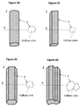
- European Patent Office
- Prior art keywords
- electrode
- biopotential sensing
- biopotential
- sensing according
- conductive
- Prior art date
- Legal status (The legal status is an assumption and is not a legal conclusion. Google has not performed a legal analysis and makes no representation as to the accuracy of the status listed.)
- Granted
Links
Images






Classifications
-
- A—HUMAN NECESSITIES
- A61—MEDICAL OR VETERINARY SCIENCE; HYGIENE
- A61B—DIAGNOSIS; SURGERY; IDENTIFICATION
- A61B5/00—Measuring for diagnostic purposes; Identification of persons
- A61B5/05—Detecting, measuring or recording for diagnosis by means of electric currents or magnetic fields; Measuring using microwaves or radio waves
- A61B5/053—Measuring electrical impedance or conductance of a portion of the body
-
- A—HUMAN NECESSITIES
- A61—MEDICAL OR VETERINARY SCIENCE; HYGIENE
- A61B—DIAGNOSIS; SURGERY; IDENTIFICATION
- A61B5/00—Measuring for diagnostic purposes; Identification of persons
- A61B5/24—Detecting, measuring or recording bioelectric or biomagnetic signals of the body or parts thereof
- A61B5/25—Bioelectric electrodes therefor
- A61B5/279—Bioelectric electrodes therefor specially adapted for particular uses
- A61B5/291—Bioelectric electrodes therefor specially adapted for particular uses for electroencephalography [EEG]
-
- A—HUMAN NECESSITIES
- A61—MEDICAL OR VETERINARY SCIENCE; HYGIENE
- A61B—DIAGNOSIS; SURGERY; IDENTIFICATION
- A61B5/00—Measuring for diagnostic purposes; Identification of persons
- A61B5/68—Arrangements of detecting, measuring or recording means, e.g. sensors, in relation to patient
- A61B5/6801—Arrangements of detecting, measuring or recording means, e.g. sensors, in relation to patient specially adapted to be attached to or worn on the body surface
- A61B5/6813—Specially adapted to be attached to a specific body part
- A61B5/6814—Head
-
- A—HUMAN NECESSITIES
- A61—MEDICAL OR VETERINARY SCIENCE; HYGIENE
- A61B—DIAGNOSIS; SURGERY; IDENTIFICATION
- A61B2562/00—Details of sensors; Constructional details of sensor housings or probes; Accessories for sensors
- A61B2562/04—Arrangements of multiple sensors of the same type
- A61B2562/046—Arrangements of multiple sensors of the same type in a matrix array
-
- A—HUMAN NECESSITIES
- A61—MEDICAL OR VETERINARY SCIENCE; HYGIENE
- A61B—DIAGNOSIS; SURGERY; IDENTIFICATION
- A61B2562/00—Details of sensors; Constructional details of sensor housings or probes; Accessories for sensors
- A61B2562/12—Manufacturing methods specially adapted for producing sensors for in-vivo measurements
- A61B2562/125—Manufacturing methods specially adapted for producing sensors for in-vivo measurements characterised by the manufacture of electrodes
Definitions
- the present description relates generally to electrodes and more specifically to dry-contact electrodes for biopotential sensing.
- Electrocardiography ECG
- EEG electro-encephalography
- bio-impedance measurements requires a good electrode-to-skin contact.
- Known solutions such as gel electrodes, ensure a good contact between the electrode and the skin with the use of conductive gels. These gels, however, require application before measurements and removal after use, and tend to dry out over time, making them cumbersome and unsuitable for certain applications, such as long time monitoring.
- a new and improved dry-contact electrode is herein proposed, which advantageously provides good skin contact and is flexible for improved user comfort.
- the new electrode is advantageously used for dry-contact biopotential measurement applications and provides good electrical conductivity even when applied to skin surfaces covered with hair, such as, for example the human scalp.
- the new dry electrode is advantageously robust and suitable for long term biopotential measurements.
- the new dry-contact electrode advantageously reduces biopotential measurement artefacts caused, for example, by the non-constant and non-equal pressure on the contact points of electrodes to the skin surface.
- an electrode for biopotential sensing comprising a main electrode base and at least a first plurality of contact pins protruding from that main electrode base and intended for making contact with a subject's skin, and wherein each pin of said first plurality of contact pins comprises a conductive mesh having an elongated pillar shape.
- the conductive mesh may have, for example, a cylindrical shape, with circular or elliptic cross-section, or a substantially cylindrical shape with one crease.
- the elongated pillar shape conductive mesh may also have a rectangular or hexagonal prism shape and the pillar may have a regular or irregular polygonal cross-section.
- the conductive mesh may be a woven fabric comprising a plurality of conductive wires or fibres designed for being flexible and ensuring conductivity of the pins.
- the elongated pillar shape conductive mesh has a width between 1 and 2.5mm and a length which is greater than the width.
- the electrode pins consist of the elongated pillar shape conductive mesh with a hollow core.
- the cylindrical conductive mesh has a resistance lower than 100 m ⁇ /cm.
- the first plurality of contact pins further comprise a tip which is configured to be in contact with the conductive mesh and the subject's skin.
- the tip is covered with a non-polarizable electrode material.
- the non-polarizable electrode material further comprises a mixture of materials containing ions that are also present in biological fluids.
- the tip is designed for being rigid and with a spherical, hemispherical or conical shape.
- the core of the conductive mesh is hollow.
- the contact pins comprise two or more conductive meshes having an elongated pillar shape.
- the core of the conductive mesh comprises a flexible core material.
- the flexible core material is an elastic and/or compressible material, such as a foam and/or a polymer.
- the flexible core material further comprises additives which make such material conductive.
- the main electrode base is made of a conductive material or a non-conductive material which contains a conductor that makes the contact with each of the pins and conductive meshes.
- the first plurality of contact pins contains four or more pins.
- the present invention also relates to a headset or biopotential monitoring system comprising an electrode for biopotential sensing according to any of the embodiments defined by the claims.
- an electrode for biopotential sensing comprising a main electrode base and at least a first plurality of contact pins protruding from that main electrode base and intended for making contact with a subject's skin, and wherein said first plurality of contact pins comprise a cylindrical conductive mesh.
- the cylindrical conductive mesh may be a woven fabric comprising a plurality of conductive wires or fibres designed for being flexible and ensuring conductivity of the pins.
- the cylindrical conductive mesh has a diameter between 1mm and 1cm and a length of at least 2mm.
- the cylindrical conductive mesh has a resistance lower than 100 m ⁇ /cm.
- the first plurality of contact pins further comprise a tip which is configured to be in contact with the subject's skin.
- the tip is covered with a non-polarizable electrode material.
- the non-polarizable electrode material further comprises a mixture of materials containing ions that are also present in biological fluids.
- the tip is designed for being rigid and with a spherical, hemispherical or conical shape.
- the core of the cylindrical conductive mesh is hollow.
- the core of the cylindrical conductive mesh comprises more cylindrical conductive mesh layers.
- the core of the cylindrical conductive mesh comprises a flexible core material.
- FIG. 1 shows a perspective side view of an exemplary electrode 100 for biopotential sensing according to the present invention.
- the electrode 100 comprises a main electrode body or base 1 and a plurality of contact pads or pins 2 protruding from that main electrode base.
- the electrode comprises at least four pins.
- the plurality of pins 2 protrude in the direction of the measurement surface or skin when the electrode 100 is applied on the subject, e.g. an area of the subject's skin, for measurement purposes.
- the main electrode base 1 serves as mechanical support for the pins 2 and is adapted for providing electrical contact between the pins and other electrical/electronic parts of a system for monitoring and processing the sensed biopotential signals (not shown).
- the main electrode base 1 may be made of a conductive material (e.g. a metal or a conductive polymer) or a non-conductive material which contains one or more conductive lines that make contact with each of the pins 2.
- a conductive material e.g. a metal or a conductive polymer
- a non-conductive material which contains one or more conductive lines that make contact with each of the pins 2.
- Such main electrode base 1 may have, but is not limited to, a disc shape.
- the electrode pins 2 comprise at least one conductive mesh 3 with an elongated pillar shape.
- the electrode pins 2 consist of such an elongated pillar shape conductive mesh 3 with a hollow core.
- the conductive mesh 3 has a cylindrical shape.
- the cylindrical conductive mesh 3 has a circular cross-section (along the line A ).
- the conductive mesh 3 is a woven fabric comprising a plurality of conductive wires or fibres, similar to a web or net, that ensures conductivity of the pins.
- the conductive mesh may be a conductive fabric known in the field of electronic shielding.
- the elongated pillar shape conductive mesh 3 has a width W between 1 and 2.5mm and a length L which is greater/longer than the width.
- the resistance of the conductive mesh is lower than 100 m ⁇ /cm.
- the pins provide flexibility to ensure a continuous mechanical contact of the conductive mesh with the skin, thereby providing a good mechanical skin-electrode-contact and or more comfort to the user.
- the length of the pin is greater than its width, which makes it suitable for biopotential electrode sensing applications.
- FIG 2 shows a second exemplary implementation of a pin 2 included in an electrode 100 for biopotential sensing according to the present invention.
- the electrode pins 2 are made of a cylindrical conductive mesh 3 with a hollow core (as in Figure 1 ) and comprise an additional spherical-shape tip 4, which will be in contact with the subject's skin.
- the shape of the tip is designed in such way that it eases penetration between hair, for example with a (hemi-)spherical shape for small diameter pins or non-dense hair.
- the tip of the pins may also have, but is not limited to, a conical shape (or a cone with rounded off tip).
- the tip of the electrode is covered with a non-polarizable electrode material, which advantageously ensures a good electronic skin-contact, that is, allows a good charge-transfer from the skin to the electrode and vice-versa.
- a non-polarizable electrode material may be, but is not limited to, silver (Ag) or silver chloride (AgCl).
- the non-polarizable material comprises a mixture of materials containing ions that are also present in biological fluids.
- the electrode pin 2 is designed to be flexible while the pin tip 4 is rigid, which allows for a tip layer to be more than 1mm so wear will not change the electrode properties, making this a durable and re-usable electrode design. With this method, the mechanical contact to the skin (provided by the flexibility of the pins 2) and the electrical contact (provided by the rigid tip 4) are separated, and can be optimized separately.
- FIG. 3 shows a third exemplary implementation of a pin 2 included in an electrode 100 for biopotential sensing according to the present invention.
- the electrode pins 2 are made of a plurality of cylindrical conductive mesh layers 3, 3b and 3c with a hollow core and comprise an additional spherical-shape tip 4.
- Figure 4 shows a fourth exemplary implementation of a pin 2 included in an electrode 100 for biopotential sensing according to the present invention.
- the electrode pins 2 are made of a cylindrical conductive mesh 3 surrounding a flexible core material 5.
- the flexible core material of the pins is an elastic and preferentially compressible material.
- the flexible core material is a polymer.
- the flexible core material may be, for example, a foam or rubber, such as polystyrene 'Styrofoam'.
- the flexible core material may comprise additives which make this core material conductive.
- Figures 5A and 5B show some generic application examples of exemplary electrodes for biopotential sensing.
- a multiple pin electrode 100 according to embodiments of the invention is applied to a curved surface 10
- the curvature is accommodated by compression or bending of the pins, i.e. the electrode pins will be compressed and make good skin contact and.
- the user comfort level will be increased, and vibrations of the electrode holder will be dampened, reducing the number of motion artefacts.
- Figures 6A, 6B, 6C and 6D show further exemplary implementations of pins included in an electrode for biopotential sensing according to the present invention.
- Figure 6A shows a fifth exemplary implementation of a pin 2 included in an electrode 100 for biopotential sensing having a conductive mesh 3 with a substantially cylindrical shape with a crease.
- Figure 6B shows a sixth exemplary implementation of a pin 2 included in an electrode 100 for biopotential sensing having a conductive mesh 3 with a rectangular prism shape and a square cross-section.
- Figure 6C shows a seventh exemplary implementation of a pin 2 included in an electrode 100 for biopotential sensing having a conductive mesh 3 with an hexagonal prism shape.
- Figure 6D shows an eight exemplary implementation of a pin 2 included in an electrode 100 for biopotential sensing having a conductive mesh 3 with a prism shape and an irregular decagon cross-section. It shall be understood that the elongated pillar shapes of Figures 6A to 6D are just examples and the cross-section of the elongated pillar shape may be a regular or irregular polygon.
- FIG. 7 illustrates a top view of an exemplary electrode 100 for biopotential sensing according to the present invention.
- the electrode comprises a main electrode body or base 1 and four contact pads or pins 2 protruding from that main electrode base.
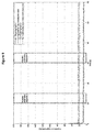
- Figure 8 shows a first graph of impedance values over time presented by a plurality of electrodes for biopotential sensing in comparison to an exemplary electrode for biopotential sensing according to the present invention.
- the impedance values are shown during the first 120 seconds after applying a headset comprising an electrode for biopotential sensing to the head of a subject. Initial large impedance values can be seen when placing the headset on the subject and when readjusting the headset at about 30 and 60 seconds.
- the measured impedance for an exemplary electrode for biopotential sensing with a conductive mesh according to the present invention is higher (around 20 kOhm) than the one measured with rigid electrodes (around 10 kOhm), but still quite low.
- the three spectra estimation segments 1, 2 and 3 correspond to the spectral power graphs shown in Figures 10 , 11 and 12 .
- Figure 9 shows a second graph of impedance values over time presented by a plurality of electrodes for biopotential sensing in comparison to an exemplary electrode for biopotential sensing according to the present invention.
- the impedance values are shown during a 60 second segment starting around 3 minutes after positioning the headset on the subject.
- the graph shows that that the impedance values are more stable and that it is higher (around 20 kOhm) for an exemplary electrode for biopotential sensing with a conductive mesh according to the present invention and for coated electrodes.
- the two spectra estimation segments 4 and 5 correspond to the spectral power graphs shown in Figures 13 and 14 .
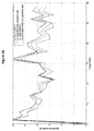
- Figure 10 shows a first graph of spectral power values from a plurality of electrodes for biopotential sensing in comparison to an exemplary electrode for biopotential sensing according to the present invention, during the first spectra estimation segment of Figure 8 .
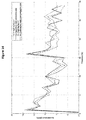
- the subject has the eyes open and the spectra shows a high noise level and no substantial difference between the plurality of electrodes for biopotential sensing used (rigid or flexible).
- Figure 11 shows a second graph of spectral power values from a plurality of electrodes for biopotential sensing in comparison to an exemplary electrode for biopotential sensing according to the present invention, during the second spectra estimation segment of Figure 8 .
- the subject has the eyes open and the spectra shows decreased noise level and no substantial difference between the plurality of electrodes for biopotential sensing used (rigid or flexible).
- Figure 12 shows a third graph of spectral power values from a plurality of electrodes for biopotential sensing in comparison to an exemplary electrode for biopotential sensing according to the present invention, during the third spectra estimation segment of Figure 8 .
- the subject has the eyes closed which increases the 10-12Hz.
- the spectra shows further decrease in noise level and no substantial difference between the plurality of electrodes for biopotential sensing used (rigid or flexible).
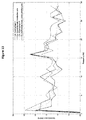
- Figure 13 shows a fourth graph of spectral power values from a plurality of electrodes for biopotential sensing in comparison to an exemplary electrode for biopotential sensing according to the present invention, during the fourth spectra estimation segment of Figure 9 .
- the subject has the eyes closed and the spectra shows a stable noise level and no substantial difference between the plurality of electrodes for biopotential sensing used (rigid or flexible).
- Figure 14 shows a fifth graph of spectral power values from a plurality of electrodes for biopotential sensing in comparison to an exemplary electrode for biopotential sensing according to the present invention, during the fifth spectra estimation segment of Figure 9 .
- the subject has the eyes open and the spectra shows a stable noise level and no substantial difference between the plurality of electrodes for biopotential sensing used (rigid or flexible).
Landscapes
- Health & Medical Sciences (AREA)
- Life Sciences & Earth Sciences (AREA)
- Medical Informatics (AREA)
- Biophysics (AREA)
- Pathology (AREA)
- Engineering & Computer Science (AREA)
- Biomedical Technology (AREA)
- Heart & Thoracic Surgery (AREA)
- Physics & Mathematics (AREA)
- Molecular Biology (AREA)
- Surgery (AREA)
- Animal Behavior & Ethology (AREA)
- General Health & Medical Sciences (AREA)
- Public Health (AREA)
- Veterinary Medicine (AREA)
- Nuclear Medicine, Radiotherapy & Molecular Imaging (AREA)
- Radiology & Medical Imaging (AREA)
- Measurement And Recording Of Electrical Phenomena And Electrical Characteristics Of The Living Body (AREA)
Abstract
Description
- The present description relates generally to electrodes and more specifically to dry-contact electrodes for biopotential sensing.
- Analysis of biopotential electrical signals generated inside the human body, for example for electrocardiography (ECG), electro-encephalography (EEG), and analysis of the response of biological tissue to imposed currents, for example for bio-impedance measurements, requires a good electrode-to-skin contact. Known solutions, such as gel electrodes, ensure a good contact between the electrode and the skin with the use of conductive gels. These gels, however, require application before measurements and removal after use, and tend to dry out over time, making them cumbersome and unsuitable for certain applications, such as long time monitoring.
- Alternatively, known dry or dry-contact electrodes are currently available in the form of electrodes with rigid pins that are pressed onto the skin. Their rigidity, however, makes such electrodes uncomfortable to wear and prone to motion artefacts. There has been also some interest in developing conductive polymer electrodes, such as the ones described in " Comb-shaped Polymer-based Dry Electrodes for EEG/ECG Measurements with High User Comfort", by Y.H. Chen et al., IEEE Engineering in Medicine and Biology Society (EMBC), 35th Annual International Conference of the IEEE, pp. 551-554, Osaka, Japan, 3-7 July, 2013. Although such electrodes present promising results, their conductivity is still low for certain applications.
- There is a motivation to improve current state of the art dry electrodes in order to improve user comfort, setup time and/or high quality biopotential measurement.
- The scope of the invention is defined by the claims.
- A new and improved dry-contact electrode is herein proposed, which advantageously provides good skin contact and is flexible for improved user comfort. According to an exemplary embodiment the new electrode is advantageously used for dry-contact biopotential measurement applications and provides good electrical conductivity even when applied to skin surfaces covered with hair, such as, for example the human scalp. According to an exemplary embodiment the new dry electrode is advantageously robust and suitable for long term biopotential measurements. According to an exemplary embodiment the new dry-contact electrode advantageously reduces biopotential measurement artefacts caused, for example, by the non-constant and non-equal pressure on the contact points of electrodes to the skin surface.
- According to an exemplary embodiment, an electrode for biopotential sensing is provided, comprising a main electrode base and at least a first plurality of contact pins protruding from that main electrode base and intended for making contact with a subject's skin, and wherein each pin of said first plurality of contact pins comprises a conductive mesh having an elongated pillar shape. According to an exemplary embodiment, the conductive mesh may have, for example, a cylindrical shape, with circular or elliptic cross-section, or a substantially cylindrical shape with one crease. The elongated pillar shape conductive mesh may also have a rectangular or hexagonal prism shape and the pillar may have a regular or irregular polygonal cross-section.
- According to an exemplary embodiment, the conductive mesh may be a woven fabric comprising a plurality of conductive wires or fibres designed for being flexible and ensuring conductivity of the pins.
- According to an exemplary embodiment, the elongated pillar shape conductive mesh has a width between 1 and 2.5mm and a length which is greater than the width.
- According to an exemplary embodiment the electrode pins consist of the elongated pillar shape conductive mesh with a hollow core.
- According to an exemplary embodiment, the cylindrical conductive mesh has a resistance lower than 100 mΩ/cm.
- According to an exemplary embodiment, the first plurality of contact pins further comprise a tip which is configured to be in contact with the conductive mesh and the subject's skin.
- According to an exemplary embodiment, the tip is covered with a non-polarizable electrode material.
- According to an exemplary embodiment, the non-polarizable electrode material further comprises a mixture of materials containing ions that are also present in biological fluids.
- According to an exemplary embodiment, the tip is designed for being rigid and with a spherical, hemispherical or conical shape.
- According to an exemplary embodiment, the core of the conductive mesh is hollow.
- According to an exemplary embodiment, the contact pins comprise two or more conductive meshes having an elongated pillar shape.
- According to an exemplary embodiment, the core of the conductive mesh comprises a flexible core material.
- According to an exemplary embodiment, the flexible core material is an elastic and/or compressible material, such as a foam and/or a polymer.
- According to an exemplary embodiment, the flexible core material further comprises additives which make such material conductive.
- According to an exemplary embodiment, the main electrode base is made of a conductive material or a non-conductive material which contains a conductor that makes the contact with each of the pins and conductive meshes.
- According to an exemplary embodiment, the first plurality of contact pins contains four or more pins.
- The present invention also relates to a headset or biopotential monitoring system comprising an electrode for biopotential sensing according to any of the embodiments defined by the claims.
- According to an exemplary embodiment, an electrode for biopotential sensing is provided, comprising a main electrode base and at least a first plurality of contact pins protruding from that main electrode base and intended for making contact with a subject's skin, and wherein said first plurality of contact pins comprise a cylindrical conductive mesh. According to an exemplary embodiment, the cylindrical conductive mesh may be a woven fabric comprising a plurality of conductive wires or fibres designed for being flexible and ensuring conductivity of the pins. According to an exemplary embodiment, the cylindrical conductive mesh has a diameter between 1mm and 1cm and a length of at least 2mm. According to an exemplary embodiment, the cylindrical conductive mesh has a resistance lower than 100 mΩ/cm. According to an exemplary embodiment, the first plurality of contact pins further comprise a tip which is configured to be in contact with the subject's skin. According to an exemplary embodiment, the tip is covered with a non-polarizable electrode material. According to an exemplary embodiment, the non-polarizable electrode material further comprises a mixture of materials containing ions that are also present in biological fluids. According to an exemplary embodiment, the tip is designed for being rigid and with a spherical, hemispherical or conical shape. According to an exemplary embodiment, the core of the cylindrical conductive mesh is hollow. According to an exemplary embodiment, the core of the cylindrical conductive mesh comprises more cylindrical conductive mesh layers. According to an exemplary embodiment, the core of the cylindrical conductive mesh comprises a flexible core material.
- The above and other aspects of the system according to the present description will be shown and explained with reference to the non-restrictive example embodiments described hereinafter.
-
Figure 1 illustrates an exemplary electrode for biopotential sensing according to the present invention. -
Figure 2 shows a second exemplary implementation of a pin included in an electrode for biopotential sensing according to the present invention. -
Figure 3 shows a third exemplary implementation of a pin included in an electrode for biopotential sensing according to the present invention. -
Figure 4 shows a fourth exemplary implementation of a pin included in an electrode for biopotential sensing according to the present invention. -
Figures 5A and 5B show some generic application examples of exemplary electrodes for biopotential sensing according to the present invention. -
Figures 6A, 6B, 6C and 6D show further exemplary implementations of pins included in an electrode for biopotential sensing according to the present invention. -
Figure 7 illustrates a top view of an exemplary electrode for biopotential sensing according to the present invention. -
Figure 8 shows a first graph of impedance values over time presented by a plurality of electrodes for biopotential sensing in comparison to an exemplary electrode for biopotential sensing according to the present invention. -
Figure 9 shows a second graph of impedance values over time presented by a plurality of electrodes for biopotential sensing in comparison to an exemplary electrode for biopotential sensing according to the present invention. -
Figures 10 ,11 ,12 ,13 and14 show graphs of spectral power values from a plurality of electrodes for biopotential sensing in comparison to an exemplary electrode for biopotential sensing according to the present invention. - In the following, in the description of exemplary embodiments, various features may be grouped together in a single embodiment, figure, or description thereof for the purpose of streamlining the disclosure and aiding in the understanding of one or more of the various inventive aspects. This is however not to be interpreted as the invention requiring more features than the ones expressly recited in the main claim. Furthermore, combinations of features of different embodiments are meant to be within the scope of the invention, as would be clearly understood by those skilled in the art. Additionally, in other instances, well-known methods, structures and techniques have not been shown in detail in order not to obscure the conciseness of the description.
-
Figure 1 shows a perspective side view of anexemplary electrode 100 for biopotential sensing according to the present invention. Theelectrode 100 comprises a main electrode body orbase 1 and a plurality of contact pads or pins 2 protruding from that main electrode base. According to an exemplary embodiment the electrode comprises at least four pins. The plurality ofpins 2 protrude in the direction of the measurement surface or skin when theelectrode 100 is applied on the subject, e.g. an area of the subject's skin, for measurement purposes. Themain electrode base 1 serves as mechanical support for thepins 2 and is adapted for providing electrical contact between the pins and other electrical/electronic parts of a system for monitoring and processing the sensed biopotential signals (not shown). Themain electrode base 1 may be made of a conductive material (e.g. a metal or a conductive polymer) or a non-conductive material which contains one or more conductive lines that make contact with each of thepins 2. Suchmain electrode base 1 may have, but is not limited to, a disc shape. According to an exemplary embodiment, the electrode pins 2 comprise at least oneconductive mesh 3 with an elongated pillar shape. According to an exemplary embodiment, the electrode pins 2 consist of such an elongated pillar shapeconductive mesh 3 with a hollow core. According to an exemplary embodiment, theconductive mesh 3 has a cylindrical shape. According to an exemplary embodiment the cylindricalconductive mesh 3 has a circular cross-section (along the line A). According to an exemplary embodiment theconductive mesh 3 is a woven fabric comprising a plurality of conductive wires or fibres, similar to a web or net, that ensures conductivity of the pins. According to an exemplary embodiment the conductive mesh may be a conductive fabric known in the field of electronic shielding. According to an exemplary embodiment, the elongated pillar shapeconductive mesh 3 has a width W between 1 and 2.5mm and a length L which is greater/longer than the width. According to an exemplary embodiment, the resistance of the conductive mesh is lower than 100 mΩ/cm. According to an exemplary embodiment, the pins provide flexibility to ensure a continuous mechanical contact of the conductive mesh with the skin, thereby providing a good mechanical skin-electrode-contact and or more comfort to the user. According to an exemplary embodiment, the length of the pin is greater than its width, which makes it suitable for biopotential electrode sensing applications. -
Figure 2 shows a second exemplary implementation of apin 2 included in anelectrode 100 for biopotential sensing according to the present invention. The electrode pins 2 are made of a cylindricalconductive mesh 3 with a hollow core (as inFigure 1 ) and comprise an additional spherical-shape tip 4, which will be in contact with the subject's skin. According to an exemplary embodiment, the shape of the tip is designed in such way that it eases penetration between hair, for example with a (hemi-)spherical shape for small diameter pins or non-dense hair. The tip of the pins may also have, but is not limited to, a conical shape (or a cone with rounded off tip). According to an exemplary embodiment, the tip of the electrode is covered with a non-polarizable electrode material, which advantageously ensures a good electronic skin-contact, that is, allows a good charge-transfer from the skin to the electrode and vice-versa. Such non-polarizable electrode material may be, but is not limited to, silver (Ag) or silver chloride (AgCl). According to another exemplary embodiment, the non-polarizable material comprises a mixture of materials containing ions that are also present in biological fluids. According to an exemplary embodiment, theelectrode pin 2 is designed to be flexible while thepin tip 4 is rigid, which allows for a tip layer to be more than 1mm so wear will not change the electrode properties, making this a durable and re-usable electrode design. With this method, the mechanical contact to the skin (provided by the flexibility of the pins 2) and the electrical contact (provided by the rigid tip 4) are separated, and can be optimized separately. -
Figure 3 shows a third exemplary implementation of apin 2 included in anelectrode 100 for biopotential sensing according to the present invention. The electrode pins 2 are made of a plurality of cylindrical conductive mesh layers 3, 3b and 3c with a hollow core and comprise an additional spherical-shape tip 4. -
Figure 4 shows a fourth exemplary implementation of apin 2 included in anelectrode 100 for biopotential sensing according to the present invention. The electrode pins 2 are made of a cylindricalconductive mesh 3 surrounding aflexible core material 5. The flexible core material of the pins is an elastic and preferentially compressible material. According to an exemplary embodiment, the flexible core material is a polymer. According to an exemplary embodiment, the flexible core material may be, for example, a foam or rubber, such as polystyrene 'Styrofoam'. According to an exemplary embodiment, the flexible core material may comprise additives which make this core material conductive. -
Figures 5A and 5B show some generic application examples of exemplary electrodes for biopotential sensing. When amultiple pin electrode 100 according to embodiments of the invention is applied to acurved surface 10, the curvature is accommodated by compression or bending of the pins, i.e. the electrode pins will be compressed and make good skin contact and. Moreover, with the flexible pins, the user comfort level will be increased, and vibrations of the electrode holder will be dampened, reducing the number of motion artefacts. -
Figures 6A, 6B, 6C and 6D show further exemplary implementations of pins included in an electrode for biopotential sensing according to the present invention.Figure 6A shows a fifth exemplary implementation of apin 2 included in anelectrode 100 for biopotential sensing having aconductive mesh 3 with a substantially cylindrical shape with a crease.Figure 6B shows a sixth exemplary implementation of apin 2 included in anelectrode 100 for biopotential sensing having aconductive mesh 3 with a rectangular prism shape and a square cross-section.Figure 6C shows a seventh exemplary implementation of apin 2 included in anelectrode 100 for biopotential sensing having aconductive mesh 3 with an hexagonal prism shape.Figure 6D shows an eight exemplary implementation of apin 2 included in anelectrode 100 for biopotential sensing having aconductive mesh 3 with a prism shape and an irregular decagon cross-section. It shall be understood that the elongated pillar shapes ofFigures 6A to 6D are just examples and the cross-section of the elongated pillar shape may be a regular or irregular polygon. -
Figure 7 illustrates a top view of anexemplary electrode 100 for biopotential sensing according to the present invention. The electrode comprises a main electrode body orbase 1 and four contact pads or pins 2 protruding from that main electrode base. -
Figure 8 shows a first graph of impedance values over time presented by a plurality of electrodes for biopotential sensing in comparison to an exemplary electrode for biopotential sensing according to the present invention. The impedance values are shown during the first 120 seconds after applying a headset comprising an electrode for biopotential sensing to the head of a subject. Initial large impedance values can be seen when placing the headset on the subject and when readjusting the headset at about 30 and 60 seconds. Overall, the measured impedance for an exemplary electrode for biopotential sensing with a conductive mesh according to the present invention is higher (around 20 kOhm) than the one measured with rigid electrodes (around 10 kOhm), but still quite low. The threespectra estimation segments Figures 10 ,11 and12 . -
Figure 9 shows a second graph of impedance values over time presented by a plurality of electrodes for biopotential sensing in comparison to an exemplary electrode for biopotential sensing according to the present invention. The impedance values are shown during a 60 second segment starting around 3 minutes after positioning the headset on the subject. The graph shows that that the impedance values are more stable and that it is higher (around 20 kOhm) for an exemplary electrode for biopotential sensing with a conductive mesh according to the present invention and for coated electrodes. The twospectra estimation segments Figures 13 and14 . -
Figure 10 shows a first graph of spectral power values from a plurality of electrodes for biopotential sensing in comparison to an exemplary electrode for biopotential sensing according to the present invention, during the first spectra estimation segment ofFigure 8 . The subject has the eyes open and the spectra shows a high noise level and no substantial difference between the plurality of electrodes for biopotential sensing used (rigid or flexible). -
Figure 11 shows a second graph of spectral power values from a plurality of electrodes for biopotential sensing in comparison to an exemplary electrode for biopotential sensing according to the present invention, during the second spectra estimation segment ofFigure 8 . The subject has the eyes open and the spectra shows decreased noise level and no substantial difference between the plurality of electrodes for biopotential sensing used (rigid or flexible). -
Figure 12 shows a third graph of spectral power values from a plurality of electrodes for biopotential sensing in comparison to an exemplary electrode for biopotential sensing according to the present invention, during the third spectra estimation segment ofFigure 8 . The subject has the eyes closed which increases the 10-12Hz. The spectra shows further decrease in noise level and no substantial difference between the plurality of electrodes for biopotential sensing used (rigid or flexible). -
Figure 13 shows a fourth graph of spectral power values from a plurality of electrodes for biopotential sensing in comparison to an exemplary electrode for biopotential sensing according to the present invention, during the fourth spectra estimation segment ofFigure 9 . The subject has the eyes closed and the spectra shows a stable noise level and no substantial difference between the plurality of electrodes for biopotential sensing used (rigid or flexible). -
Figure 14 shows a fifth graph of spectral power values from a plurality of electrodes for biopotential sensing in comparison to an exemplary electrode for biopotential sensing according to the present invention, during the fifth spectra estimation segment ofFigure 9 . The subject has the eyes open and the spectra shows a stable noise level and no substantial difference between the plurality of electrodes for biopotential sensing used (rigid or flexible). - In
Figures 10 to 14 we note that there is environment noise around 16Hz which is equally likely present in all electrodes used. In summary, the quality of the EEG signal obtained using an exemplary electrode for biopotential sensing according to the present invention comes close to current state of the art dry-contact rigid electrodes.
Claims (15)
- An electrode (100) for biopotential sensing comprising a main electrode base (1) and at least a first plurality of contact pins (2) protruding from that main electrode base and intended for making contact with a subject's skin, characterized in that each of said first plurality of contact pins (2) comprises at least one conductive mesh (3) having an elongated pillar shape.
- An electrode (100) for biopotential sensing according to claim 1 wherein said conductive mesh (3) is a woven fabric comprising a plurality of conductive wires or fibres designed for being flexible and ensuring conductivity of the pins.
- An electrode (100) for biopotential sensing according to any preceding claim wherein said elongated pillar shape conductive mesh (3) has a width (W) between 1 and 2.5mm and a length (L) which is greater than the width (W) .
- An electrode (100) for biopotential sensing according to any preceding claim wherein said first plurality of contact pins (2) further comprise a tip (4) which is configured to be in contact with the conductive mesh and the subject's skin.
- An electrode (100) for biopotential sensing according to claim 4 wherein said tip (4) is covered with a non-polarizable electrode material.
- An electrode (100) for biopotential sensing according to claim 5 wherein said non-polarizable electrode material further comprises a mixture of materials containing ions that are also present in biological fluids.
- An electrode (100) for biopotential sensing according to any of claims 4 to 6 wherein said tip (4) is designed for being rigid and with a spherical, hemispherical or conical shape.
- An electrode (100) for biopotential sensing according to any preceding claim wherein the core of the conductive mesh (3) is hollow.
- An electrode (100) for biopotential sensing according to any of claims 1 to 7 wherein each of said first plurality of contact pins (2) comprises two or more conductive meshes (3,3b,3c) having an elongated pillar shape.
- An electrode (100) for biopotential sensing according to any of claims 1 to 7 wherein the core of the conductive mesh (3) comprises a flexible core material (5).
- An electrode (100) for biopotential sensing according to claim 10 wherein said flexible core material (5) is an elastic and/or compressible material, such as a foam and/or a polymer.
- An electrode (100) for biopotential sensing according to claims 10 or 11 wherein said flexible core material (5) further comprises additives which make such material conductive.
- An electrode (100) for biopotential sensing according to any preceding claim wherein the main electrode base (1) is made of a conductive material or a non-conductive material which contains one or more conductors that make electrical contact with each of the conductive meshes (3).
- An electrode (100) for biopotential sensing according to any preceding claim wherein said first plurality of contact pins (2) contains four or more pins.
- A headset or biopotential monitoring system comprising an electrode for biopotential sensing according to any of the preceding claims.
Priority Applications (1)
| Application Number | Priority Date | Filing Date | Title |
|---|---|---|---|
| EP15198642.9A EP3033994B1 (en) | 2014-12-17 | 2015-12-09 | Electrode for biopotential sensing |
Applications Claiming Priority (2)
| Application Number | Priority Date | Filing Date | Title |
|---|---|---|---|
| EP14198435 | 2014-12-17 | ||
| EP15198642.9A EP3033994B1 (en) | 2014-12-17 | 2015-12-09 | Electrode for biopotential sensing |
Publications (2)
| Publication Number | Publication Date |
|---|---|
| EP3033994A1 true EP3033994A1 (en) | 2016-06-22 |
| EP3033994B1 EP3033994B1 (en) | 2024-05-15 |
Family
ID=52231857
Family Applications (1)
| Application Number | Title | Priority Date | Filing Date |
|---|---|---|---|
| EP15198642.9A Active EP3033994B1 (en) | 2014-12-17 | 2015-12-09 | Electrode for biopotential sensing |
Country Status (2)
| Country | Link |
|---|---|
| US (1) | US9498148B2 (en) |
| EP (1) | EP3033994B1 (en) |
Families Citing this family (13)
| Publication number | Priority date | Publication date | Assignee | Title |
|---|---|---|---|---|
| US12201427B2 (en) | 2012-06-14 | 2025-01-21 | Medibotics Llc | Headband with brain activity sensors |
| US11850052B2 (en) | 2014-01-28 | 2023-12-26 | Medibotics Llc | Dry EEG electrode for use on a hair-covered portion of a person's head |
| KR101727149B1 (en) * | 2015-10-22 | 2017-04-14 | (주)와이브레인 | Bio-signal sensing electrode and method for preparing the same |
| KR101961535B1 (en) * | 2017-01-10 | 2019-07-17 | 전자부품연구원 | Sensors for measuring skin conductivity and methods for manufacturing the same |
| CN111669984B (en) | 2017-12-01 | 2023-09-29 | 泽图有限公司 | Head-mounted components and electrodes for sensing biopotentials and methods of operating the same |
| JP6354969B1 (en) * | 2017-12-15 | 2018-07-11 | 晶朗 木村 | Electroencephalogram detection electrode |
| WO2019159747A1 (en) * | 2018-02-16 | 2019-08-22 | ソニー株式会社 | Electrode and sensor |
| US11109787B2 (en) * | 2018-05-21 | 2021-09-07 | Vine Medical LLC | Multi-tip probe for obtaining bioelectrical measurements |
| EP3871595B1 (en) * | 2018-10-26 | 2023-09-20 | Sumitomo Bakelite Co., Ltd. | Bioelectrode, biological sensor, and biological signal measurement system |
| JP6931738B2 (en) * | 2018-11-09 | 2021-09-08 | 住友ベークライト株式会社 | Bioelectrodes, biosensors and biosignal measurement systems |
| US20250204830A1 (en) * | 2022-03-22 | 2025-06-26 | Ntt Research, Inc. | Flexible dry electrodes |
| JP2024010553A (en) * | 2022-07-12 | 2024-01-24 | 住友ベークライト株式会社 | Biosignal measurement electrode, biosignal measurement device, and biosignal measurement method |
| GB2638295A (en) * | 2024-06-17 | 2025-08-20 | B Secur Ltd | Animal health monitor device, system and method |
Citations (2)
| Publication number | Priority date | Publication date | Assignee | Title |
|---|---|---|---|---|
| US20020016538A1 (en) * | 1998-05-26 | 2002-02-07 | Ineedme.Com, Inc. | Electrode sensor |
| US20020177767A1 (en) * | 2000-05-16 | 2002-11-28 | Steve Burton | Sensor for biopotential measurements |
Family Cites Families (8)
| Publication number | Priority date | Publication date | Assignee | Title |
|---|---|---|---|---|
| US4967038A (en) * | 1986-12-16 | 1990-10-30 | Sam Techology Inc. | Dry electrode brain wave recording system |
| US5411527A (en) * | 1989-05-03 | 1995-05-02 | Intermedics, Inc. | Difibrillation electrodes and implantation |
| US8019401B1 (en) * | 2006-12-04 | 2011-09-13 | Smithmarks, Inc. | Stretchable electrode and method of making physiologic measurements |
| ES2409734T3 (en) * | 2006-12-08 | 2013-06-27 | Fraunhofer-Gesellschaft zur Förderung der angewandten Forschung e.V. | Dry electrode cap for electroencephalography |
| WO2009134763A1 (en) * | 2008-04-29 | 2009-11-05 | Board of Governors for Higher Education, State of Rhode Island and the Providence Plantations | Biomedical sensors usable on un-prepared contact surfaces |
| TWI481383B (en) * | 2009-09-25 | 2015-04-21 | Univ Nat Chiao Tung | Biosensor and electrode structure thereof |
| AT511264B1 (en) * | 2011-03-21 | 2013-06-15 | Christoph Dipl Ing Dr Techn Guger | DEVICE FOR CREATING ELECTRODE ARRANGEMENTS |
| US20150238100A1 (en) * | 2014-02-27 | 2015-08-27 | National Chiao Tung University | Sensor electrode device |
-
2015
- 2015-12-09 EP EP15198642.9A patent/EP3033994B1/en active Active
- 2015-12-17 US US14/972,661 patent/US9498148B2/en active Active
Patent Citations (2)
| Publication number | Priority date | Publication date | Assignee | Title |
|---|---|---|---|---|
| US20020016538A1 (en) * | 1998-05-26 | 2002-02-07 | Ineedme.Com, Inc. | Electrode sensor |
| US20020177767A1 (en) * | 2000-05-16 | 2002-11-28 | Steve Burton | Sensor for biopotential measurements |
Non-Patent Citations (1)
| Title |
|---|
| Y.H. CHEN ET AL.: "Comb-shaped Polymer based Dry Electrodes for EEG/ECG Measurements with High User Comfort", IEEE ENGINEERING IN MEDICINE AND BIOLOGY SOCIETY (EMBC), 35TH ANNUAL INTERNATIONAL CONFERENCE OF THE IEEE, 3 July 2013 (2013-07-03), pages 551 - 554, XP032488957, DOI: doi:10.1109/EMBC.2013.6609559 |
Also Published As
| Publication number | Publication date |
|---|---|
| US20160174859A1 (en) | 2016-06-23 |
| US9498148B2 (en) | 2016-11-22 |
| EP3033994B1 (en) | 2024-05-15 |
Similar Documents
| Publication | Publication Date | Title |
|---|---|---|
| EP3033994B1 (en) | Electrode for biopotential sensing | |
| US12257058B2 (en) | Brush electrode | |
| US11850052B2 (en) | Dry EEG electrode for use on a hair-covered portion of a person's head | |
| CN114206219B (en) | EEG signal measurement method and system | |
| CN102293648B (en) | Biological signal detection electrode and biological signal detection apparatus | |
| JP5277405B2 (en) | Electroencephalogram measurement electrode, cap with electroencephalogram measurement electrode, and electroencephalogram measurement apparatus | |
| US12527508B2 (en) | Elastic electroencephalography dry electrode, electroencephalography device and application system | |
| JP6112534B2 (en) | EEG measurement electrode, EEG measurement electrode cap with EEG measurement electrode | |
| JP2013509251A (en) | Biological electrode | |
| JP6449046B2 (en) | EEG electrode | |
| WO2016136629A1 (en) | Brain wave measurement electrode | |
| US20150238100A1 (en) | Sensor electrode device | |
| JP2016163688A (en) | Brain wave measuring electrode | |
| CN110916651A (en) | Skin dry electrode | |
| CN109009104A (en) | Electrode, wearable component and system | |
| US20230346284A1 (en) | Dry Electrode with Sliding Electroconductive Protrusions for Use on a Hair-Covered Area of a Person's Head | |
| US20170080208A1 (en) | A Stimulation Electrode | |
| JP6381968B2 (en) | EEG measurement apparatus and EEG measurement method | |
| JP2019107428A (en) | Brain wave detecting electrode | |
| JP2022137320A (en) | Electrodes for biological information measurement | |
| US20250070107A1 (en) | Electrode Comprising a Plurality of Deformable, Proximally-Diverging Electroconductive Protrusions | |
| CN217365889U (en) | Novel highly comfortable elastic electroencephalogram dry electrode, electroencephalogram equipment and application system | |
| Grozea et al. | Bristlesensors—soft, flexible dry EEG electrodes for neurofeedback and BCI applications |
Legal Events
| Date | Code | Title | Description |
|---|---|---|---|
| PUAI | Public reference made under article 153(3) epc to a published international application that has entered the european phase |
Free format text: ORIGINAL CODE: 0009012 |
|
| AK | Designated contracting states |
Kind code of ref document: A1 Designated state(s): AL AT BE BG CH CY CZ DE DK EE ES FI FR GB GR HR HU IE IS IT LI LT LU LV MC MK MT NL NO PL PT RO RS SE SI SK SM TR |
|
| AX | Request for extension of the european patent |
Extension state: BA ME |
|
| STAA | Information on the status of an ep patent application or granted ep patent |
Free format text: STATUS: REQUEST FOR EXAMINATION WAS MADE |
|
| 17P | Request for examination filed |
Effective date: 20161213 |
|
| RBV | Designated contracting states (corrected) |
Designated state(s): AL AT BE BG CH CY CZ DE DK EE ES FI FR GB GR HR HU IE IS IT LI LT LU LV MC MK MT NL NO PL PT RO RS SE SI SK SM TR |
|
| STAA | Information on the status of an ep patent application or granted ep patent |
Free format text: STATUS: EXAMINATION IS IN PROGRESS |
|
| 17Q | First examination report despatched |
Effective date: 20201030 |
|
| REG | Reference to a national code |
Ref country code: DE Ref legal event code: R079 Free format text: PREVIOUS MAIN CLASS: A61B0005040200 Ipc: A61B0005053000 Ref document number: 602015088694 Country of ref document: DE |
|
| GRAP | Despatch of communication of intention to grant a patent |
Free format text: ORIGINAL CODE: EPIDOSNIGR1 |
|
| STAA | Information on the status of an ep patent application or granted ep patent |
Free format text: STATUS: GRANT OF PATENT IS INTENDED |
|
| RIC1 | Information provided on ipc code assigned before grant |
Ipc: A61B 5/369 20210101ALI20231124BHEP Ipc: A61B 5/318 20210101ALI20231124BHEP Ipc: A61B 5/053 20060101AFI20231124BHEP |
|
| INTG | Intention to grant announced |
Effective date: 20231219 |
|
| P01 | Opt-out of the competence of the unified patent court (upc) registered |
Effective date: 20240208 |
|
| GRAS | Grant fee paid |
Free format text: ORIGINAL CODE: EPIDOSNIGR3 |
|
| GRAA | (expected) grant |
Free format text: ORIGINAL CODE: 0009210 |
|
| STAA | Information on the status of an ep patent application or granted ep patent |
Free format text: STATUS: THE PATENT HAS BEEN GRANTED |
|
| AK | Designated contracting states |
Kind code of ref document: B1 Designated state(s): AL AT BE BG CH CY CZ DE DK EE ES FI FR GB GR HR HU IE IS IT LI LT LU LV MC MK MT NL NO PL PT RO RS SE SI SK SM TR |
|
| REG | Reference to a national code |
Ref country code: CH Ref legal event code: EP Ref country code: GB Ref legal event code: FG4D |
|
| REG | Reference to a national code |
Ref country code: IE Ref legal event code: FG4D |
|
| REG | Reference to a national code |
Ref country code: DE Ref legal event code: R096 Ref document number: 602015088694 Country of ref document: DE |
|
| REG | Reference to a national code |
Ref country code: LT Ref legal event code: MG9D |
|
| REG | Reference to a national code |
Ref country code: NL Ref legal event code: MP Effective date: 20240515 |
|
| PG25 | Lapsed in a contracting state [announced via postgrant information from national office to epo] |
Ref country code: IS Free format text: LAPSE BECAUSE OF FAILURE TO SUBMIT A TRANSLATION OF THE DESCRIPTION OR TO PAY THE FEE WITHIN THE PRESCRIBED TIME-LIMIT Effective date: 20240915 |
|
| PG25 | Lapsed in a contracting state [announced via postgrant information from national office to epo] |
Ref country code: BG Free format text: LAPSE BECAUSE OF FAILURE TO SUBMIT A TRANSLATION OF THE DESCRIPTION OR TO PAY THE FEE WITHIN THE PRESCRIBED TIME-LIMIT Effective date: 20240515 |
|
| PG25 | Lapsed in a contracting state [announced via postgrant information from national office to epo] |
Ref country code: HR Free format text: LAPSE BECAUSE OF FAILURE TO SUBMIT A TRANSLATION OF THE DESCRIPTION OR TO PAY THE FEE WITHIN THE PRESCRIBED TIME-LIMIT Effective date: 20240515 Ref country code: FI Free format text: LAPSE BECAUSE OF FAILURE TO SUBMIT A TRANSLATION OF THE DESCRIPTION OR TO PAY THE FEE WITHIN THE PRESCRIBED TIME-LIMIT Effective date: 20240515 |
|
| PG25 | Lapsed in a contracting state [announced via postgrant information from national office to epo] |
Ref country code: GR Free format text: LAPSE BECAUSE OF FAILURE TO SUBMIT A TRANSLATION OF THE DESCRIPTION OR TO PAY THE FEE WITHIN THE PRESCRIBED TIME-LIMIT Effective date: 20240816 |
|
| PG25 | Lapsed in a contracting state [announced via postgrant information from national office to epo] |
Ref country code: PT Free format text: LAPSE BECAUSE OF FAILURE TO SUBMIT A TRANSLATION OF THE DESCRIPTION OR TO PAY THE FEE WITHIN THE PRESCRIBED TIME-LIMIT Effective date: 20240916 |
|
| REG | Reference to a national code |
Ref country code: AT Ref legal event code: MK05 Ref document number: 1686218 Country of ref document: AT Kind code of ref document: T Effective date: 20240515 |
|
| PG25 | Lapsed in a contracting state [announced via postgrant information from national office to epo] |
Ref country code: NL Free format text: LAPSE BECAUSE OF FAILURE TO SUBMIT A TRANSLATION OF THE DESCRIPTION OR TO PAY THE FEE WITHIN THE PRESCRIBED TIME-LIMIT Effective date: 20240515 |
|
| PG25 | Lapsed in a contracting state [announced via postgrant information from national office to epo] |
Ref country code: ES Free format text: LAPSE BECAUSE OF FAILURE TO SUBMIT A TRANSLATION OF THE DESCRIPTION OR TO PAY THE FEE WITHIN THE PRESCRIBED TIME-LIMIT Effective date: 20240515 |
|
| PG25 | Lapsed in a contracting state [announced via postgrant information from national office to epo] |
Ref country code: AT Free format text: LAPSE BECAUSE OF FAILURE TO SUBMIT A TRANSLATION OF THE DESCRIPTION OR TO PAY THE FEE WITHIN THE PRESCRIBED TIME-LIMIT Effective date: 20240515 |
|
| PG25 | Lapsed in a contracting state [announced via postgrant information from national office to epo] |
Ref country code: PL Free format text: LAPSE BECAUSE OF FAILURE TO SUBMIT A TRANSLATION OF THE DESCRIPTION OR TO PAY THE FEE WITHIN THE PRESCRIBED TIME-LIMIT Effective date: 20240515 |
|
| PG25 | Lapsed in a contracting state [announced via postgrant information from national office to epo] |
Ref country code: LV Free format text: LAPSE BECAUSE OF FAILURE TO SUBMIT A TRANSLATION OF THE DESCRIPTION OR TO PAY THE FEE WITHIN THE PRESCRIBED TIME-LIMIT Effective date: 20240515 |
|
| PG25 | Lapsed in a contracting state [announced via postgrant information from national office to epo] |
Ref country code: PT Free format text: LAPSE BECAUSE OF FAILURE TO SUBMIT A TRANSLATION OF THE DESCRIPTION OR TO PAY THE FEE WITHIN THE PRESCRIBED TIME-LIMIT Effective date: 20240916 Ref country code: PL Free format text: LAPSE BECAUSE OF FAILURE TO SUBMIT A TRANSLATION OF THE DESCRIPTION OR TO PAY THE FEE WITHIN THE PRESCRIBED TIME-LIMIT Effective date: 20240515 Ref country code: NO Free format text: LAPSE BECAUSE OF FAILURE TO SUBMIT A TRANSLATION OF THE DESCRIPTION OR TO PAY THE FEE WITHIN THE PRESCRIBED TIME-LIMIT Effective date: 20240815 Ref country code: NL Free format text: LAPSE BECAUSE OF FAILURE TO SUBMIT A TRANSLATION OF THE DESCRIPTION OR TO PAY THE FEE WITHIN THE PRESCRIBED TIME-LIMIT Effective date: 20240515 Ref country code: LV Free format text: LAPSE BECAUSE OF FAILURE TO SUBMIT A TRANSLATION OF THE DESCRIPTION OR TO PAY THE FEE WITHIN THE PRESCRIBED TIME-LIMIT Effective date: 20240515 Ref country code: IS Free format text: LAPSE BECAUSE OF FAILURE TO SUBMIT A TRANSLATION OF THE DESCRIPTION OR TO PAY THE FEE WITHIN THE PRESCRIBED TIME-LIMIT Effective date: 20240915 Ref country code: HR Free format text: LAPSE BECAUSE OF FAILURE TO SUBMIT A TRANSLATION OF THE DESCRIPTION OR TO PAY THE FEE WITHIN THE PRESCRIBED TIME-LIMIT Effective date: 20240515 Ref country code: GR Free format text: LAPSE BECAUSE OF FAILURE TO SUBMIT A TRANSLATION OF THE DESCRIPTION OR TO PAY THE FEE WITHIN THE PRESCRIBED TIME-LIMIT Effective date: 20240816 Ref country code: FI Free format text: LAPSE BECAUSE OF FAILURE TO SUBMIT A TRANSLATION OF THE DESCRIPTION OR TO PAY THE FEE WITHIN THE PRESCRIBED TIME-LIMIT Effective date: 20240515 Ref country code: ES Free format text: LAPSE BECAUSE OF FAILURE TO SUBMIT A TRANSLATION OF THE DESCRIPTION OR TO PAY THE FEE WITHIN THE PRESCRIBED TIME-LIMIT Effective date: 20240515 Ref country code: BG Free format text: LAPSE BECAUSE OF FAILURE TO SUBMIT A TRANSLATION OF THE DESCRIPTION OR TO PAY THE FEE WITHIN THE PRESCRIBED TIME-LIMIT Effective date: 20240515 Ref country code: AT Free format text: LAPSE BECAUSE OF FAILURE TO SUBMIT A TRANSLATION OF THE DESCRIPTION OR TO PAY THE FEE WITHIN THE PRESCRIBED TIME-LIMIT Effective date: 20240515 Ref country code: RS Free format text: LAPSE BECAUSE OF FAILURE TO SUBMIT A TRANSLATION OF THE DESCRIPTION OR TO PAY THE FEE WITHIN THE PRESCRIBED TIME-LIMIT Effective date: 20240815 |
|
| PG25 | Lapsed in a contracting state [announced via postgrant information from national office to epo] |
Ref country code: DK Free format text: LAPSE BECAUSE OF FAILURE TO SUBMIT A TRANSLATION OF THE DESCRIPTION OR TO PAY THE FEE WITHIN THE PRESCRIBED TIME-LIMIT Effective date: 20240515 |
|
| PG25 | Lapsed in a contracting state [announced via postgrant information from national office to epo] |
Ref country code: EE Free format text: LAPSE BECAUSE OF FAILURE TO SUBMIT A TRANSLATION OF THE DESCRIPTION OR TO PAY THE FEE WITHIN THE PRESCRIBED TIME-LIMIT Effective date: 20240515 |
|
| PG25 | Lapsed in a contracting state [announced via postgrant information from national office to epo] |
Ref country code: CZ Free format text: LAPSE BECAUSE OF FAILURE TO SUBMIT A TRANSLATION OF THE DESCRIPTION OR TO PAY THE FEE WITHIN THE PRESCRIBED TIME-LIMIT Effective date: 20240515 |
|
| PG25 | Lapsed in a contracting state [announced via postgrant information from national office to epo] |
Ref country code: SK Free format text: LAPSE BECAUSE OF FAILURE TO SUBMIT A TRANSLATION OF THE DESCRIPTION OR TO PAY THE FEE WITHIN THE PRESCRIBED TIME-LIMIT Effective date: 20240515 Ref country code: RO Free format text: LAPSE BECAUSE OF FAILURE TO SUBMIT A TRANSLATION OF THE DESCRIPTION OR TO PAY THE FEE WITHIN THE PRESCRIBED TIME-LIMIT Effective date: 20240515 |
|
| PG25 | Lapsed in a contracting state [announced via postgrant information from national office to epo] |
Ref country code: SM Free format text: LAPSE BECAUSE OF FAILURE TO SUBMIT A TRANSLATION OF THE DESCRIPTION OR TO PAY THE FEE WITHIN THE PRESCRIBED TIME-LIMIT Effective date: 20240515 |
|
| PG25 | Lapsed in a contracting state [announced via postgrant information from national office to epo] |
Ref country code: SM Free format text: LAPSE BECAUSE OF FAILURE TO SUBMIT A TRANSLATION OF THE DESCRIPTION OR TO PAY THE FEE WITHIN THE PRESCRIBED TIME-LIMIT Effective date: 20240515 Ref country code: SK Free format text: LAPSE BECAUSE OF FAILURE TO SUBMIT A TRANSLATION OF THE DESCRIPTION OR TO PAY THE FEE WITHIN THE PRESCRIBED TIME-LIMIT Effective date: 20240515 Ref country code: RO Free format text: LAPSE BECAUSE OF FAILURE TO SUBMIT A TRANSLATION OF THE DESCRIPTION OR TO PAY THE FEE WITHIN THE PRESCRIBED TIME-LIMIT Effective date: 20240515 Ref country code: EE Free format text: LAPSE BECAUSE OF FAILURE TO SUBMIT A TRANSLATION OF THE DESCRIPTION OR TO PAY THE FEE WITHIN THE PRESCRIBED TIME-LIMIT Effective date: 20240515 Ref country code: DK Free format text: LAPSE BECAUSE OF FAILURE TO SUBMIT A TRANSLATION OF THE DESCRIPTION OR TO PAY THE FEE WITHIN THE PRESCRIBED TIME-LIMIT Effective date: 20240515 Ref country code: CZ Free format text: LAPSE BECAUSE OF FAILURE TO SUBMIT A TRANSLATION OF THE DESCRIPTION OR TO PAY THE FEE WITHIN THE PRESCRIBED TIME-LIMIT Effective date: 20240515 |
|
| PG25 | Lapsed in a contracting state [announced via postgrant information from national office to epo] |
Ref country code: IT Free format text: LAPSE BECAUSE OF FAILURE TO SUBMIT A TRANSLATION OF THE DESCRIPTION OR TO PAY THE FEE WITHIN THE PRESCRIBED TIME-LIMIT Effective date: 20240515 |
|
| REG | Reference to a national code |
Ref country code: DE Ref legal event code: R097 Ref document number: 602015088694 Country of ref document: DE |
|
| PLBE | No opposition filed within time limit |
Free format text: ORIGINAL CODE: 0009261 |
|
| STAA | Information on the status of an ep patent application or granted ep patent |
Free format text: STATUS: NO OPPOSITION FILED WITHIN TIME LIMIT |
|
| 26N | No opposition filed |
Effective date: 20250218 |
|
| PG25 | Lapsed in a contracting state [announced via postgrant information from national office to epo] |
Ref country code: SI Free format text: LAPSE BECAUSE OF FAILURE TO SUBMIT A TRANSLATION OF THE DESCRIPTION OR TO PAY THE FEE WITHIN THE PRESCRIBED TIME-LIMIT Effective date: 20240515 |
|
| PG25 | Lapsed in a contracting state [announced via postgrant information from national office to epo] |
Ref country code: MC Free format text: LAPSE BECAUSE OF FAILURE TO SUBMIT A TRANSLATION OF THE DESCRIPTION OR TO PAY THE FEE WITHIN THE PRESCRIBED TIME-LIMIT Effective date: 20240515 |
|
| REG | Reference to a national code |
Ref country code: CH Ref legal event code: PL |
|
| PG25 | Lapsed in a contracting state [announced via postgrant information from national office to epo] |
Ref country code: LU Free format text: LAPSE BECAUSE OF NON-PAYMENT OF DUE FEES Effective date: 20241209 |
|
| GBPC | Gb: european patent ceased through non-payment of renewal fee |
Effective date: 20241209 |
|
| PG25 | Lapsed in a contracting state [announced via postgrant information from national office to epo] |
Ref country code: SE Free format text: LAPSE BECAUSE OF FAILURE TO SUBMIT A TRANSLATION OF THE DESCRIPTION OR TO PAY THE FEE WITHIN THE PRESCRIBED TIME-LIMIT Effective date: 20240515 |
|
| REG | Reference to a national code |
Ref country code: BE Ref legal event code: MM Effective date: 20241231 |
|
| PG25 | Lapsed in a contracting state [announced via postgrant information from national office to epo] |
Ref country code: BE Free format text: LAPSE BECAUSE OF NON-PAYMENT OF DUE FEES Effective date: 20241231 Ref country code: GB Free format text: LAPSE BECAUSE OF NON-PAYMENT OF DUE FEES Effective date: 20241209 |
|
| PG25 | Lapsed in a contracting state [announced via postgrant information from national office to epo] |
Ref country code: CH Free format text: LAPSE BECAUSE OF NON-PAYMENT OF DUE FEES Effective date: 20241231 |
|
| PG25 | Lapsed in a contracting state [announced via postgrant information from national office to epo] |
Ref country code: IE Free format text: LAPSE BECAUSE OF NON-PAYMENT OF DUE FEES Effective date: 20241209 |
|
| PGFP | Annual fee paid to national office [announced via postgrant information from national office to epo] |
Ref country code: DE Payment date: 20251126 Year of fee payment: 11 |
|
| PGFP | Annual fee paid to national office [announced via postgrant information from national office to epo] |
Ref country code: FR Payment date: 20251120 Year of fee payment: 11 |