EP3032708A1 - Rotor for electric motor, electric supercharger, and electric-motor assisted supercharger - Google Patents
Rotor for electric motor, electric supercharger, and electric-motor assisted supercharger Download PDFInfo
- Publication number
- EP3032708A1 EP3032708A1 EP15196301.4A EP15196301A EP3032708A1 EP 3032708 A1 EP3032708 A1 EP 3032708A1 EP 15196301 A EP15196301 A EP 15196301A EP 3032708 A1 EP3032708 A1 EP 3032708A1
- Authority
- EP
- European Patent Office
- Prior art keywords
- rotor
- shaft
- magnet
- plate
- assembly
- Prior art date
- Legal status (The legal status is an assumption and is not a legal conclusion. Google has not performed a legal analysis and makes no representation as to the accuracy of the status listed.)
- Withdrawn
Links
- 238000002485 combustion reaction Methods 0.000 claims description 3
- 125000006850 spacer group Chemical group 0.000 abstract description 59
- 238000003780 insertion Methods 0.000 abstract description 2
- 230000037431 insertion Effects 0.000 abstract description 2
- 230000000052 comparative effect Effects 0.000 description 10
- 238000000034 method Methods 0.000 description 6
- 238000005452 bending Methods 0.000 description 5
- 230000000694 effects Effects 0.000 description 5
- 230000013011 mating Effects 0.000 description 5
- 239000003921 oil Substances 0.000 description 4
- 239000000470 constituent Substances 0.000 description 3
- 238000012937 correction Methods 0.000 description 3
- 230000007423 decrease Effects 0.000 description 2
- 239000010687 lubricating oil Substances 0.000 description 2
- 238000012986 modification Methods 0.000 description 2
- 230000004048 modification Effects 0.000 description 2
- 238000012546 transfer Methods 0.000 description 2
- 230000005540 biological transmission Effects 0.000 description 1
- 239000000919 ceramic Substances 0.000 description 1
- 230000008602 contraction Effects 0.000 description 1
- 230000003247 decreasing effect Effects 0.000 description 1
- 238000003825 pressing Methods 0.000 description 1
- 238000004904 shortening Methods 0.000 description 1
- 238000003466 welding Methods 0.000 description 1
Images


Classifications
-
- H—ELECTRICITY
- H02—GENERATION; CONVERSION OR DISTRIBUTION OF ELECTRIC POWER
- H02K—DYNAMO-ELECTRIC MACHINES
- H02K1/00—Details of the magnetic circuit
- H02K1/06—Details of the magnetic circuit characterised by the shape, form or construction
- H02K1/22—Rotating parts of the magnetic circuit
- H02K1/28—Means for mounting or fastening rotating magnetic parts on to, or to, the rotor structures
-
- F—MECHANICAL ENGINEERING; LIGHTING; HEATING; WEAPONS; BLASTING
- F01—MACHINES OR ENGINES IN GENERAL; ENGINE PLANTS IN GENERAL; STEAM ENGINES
- F01D—NON-POSITIVE DISPLACEMENT MACHINES OR ENGINES, e.g. STEAM TURBINES
- F01D15/00—Adaptations of machines or engines for special use; Combinations of engines with devices driven thereby
-
- F—MECHANICAL ENGINEERING; LIGHTING; HEATING; WEAPONS; BLASTING
- F01—MACHINES OR ENGINES IN GENERAL; ENGINE PLANTS IN GENERAL; STEAM ENGINES
- F01D—NON-POSITIVE DISPLACEMENT MACHINES OR ENGINES, e.g. STEAM TURBINES
- F01D25/00—Component parts, details, or accessories, not provided for in, or of interest apart from, other groups
- F01D25/24—Casings; Casing parts, e.g. diaphragms, casing fastenings
-
- F—MECHANICAL ENGINEERING; LIGHTING; HEATING; WEAPONS; BLASTING
- F01—MACHINES OR ENGINES IN GENERAL; ENGINE PLANTS IN GENERAL; STEAM ENGINES
- F01D—NON-POSITIVE DISPLACEMENT MACHINES OR ENGINES, e.g. STEAM TURBINES
- F01D5/00—Blades; Blade-carrying members; Heating, heat-insulating, cooling or antivibration means on the blades or the members
- F01D5/02—Blade-carrying members, e.g. rotors
-
- F—MECHANICAL ENGINEERING; LIGHTING; HEATING; WEAPONS; BLASTING
- F02—COMBUSTION ENGINES; HOT-GAS OR COMBUSTION-PRODUCT ENGINE PLANTS
- F02B—INTERNAL-COMBUSTION PISTON ENGINES; COMBUSTION ENGINES IN GENERAL
- F02B37/00—Engines characterised by provision of pumps driven at least for part of the time by exhaust
-
- F—MECHANICAL ENGINEERING; LIGHTING; HEATING; WEAPONS; BLASTING
- F02—COMBUSTION ENGINES; HOT-GAS OR COMBUSTION-PRODUCT ENGINE PLANTS
- F02B—INTERNAL-COMBUSTION PISTON ENGINES; COMBUSTION ENGINES IN GENERAL
- F02B37/00—Engines characterised by provision of pumps driven at least for part of the time by exhaust
- F02B37/04—Engines with exhaust drive and other drive of pumps, e.g. with exhaust-driven pump and mechanically-driven second pump
- F02B37/10—Engines with exhaust drive and other drive of pumps, e.g. with exhaust-driven pump and mechanically-driven second pump at least one pump being alternatively or simultaneously driven by exhaust and other drive, e.g. by pressurised fluid from a reservoir or an engine-driven pump
-
- F—MECHANICAL ENGINEERING; LIGHTING; HEATING; WEAPONS; BLASTING
- F04—POSITIVE - DISPLACEMENT MACHINES FOR LIQUIDS; PUMPS FOR LIQUIDS OR ELASTIC FLUIDS
- F04D—NON-POSITIVE-DISPLACEMENT PUMPS
- F04D25/00—Pumping installations or systems
- F04D25/02—Units comprising pumps and their driving means
- F04D25/06—Units comprising pumps and their driving means the pump being electrically driven
-
- F—MECHANICAL ENGINEERING; LIGHTING; HEATING; WEAPONS; BLASTING
- F04—POSITIVE - DISPLACEMENT MACHINES FOR LIQUIDS; PUMPS FOR LIQUIDS OR ELASTIC FLUIDS
- F04D—NON-POSITIVE-DISPLACEMENT PUMPS
- F04D29/00—Details, component parts, or accessories
- F04D29/26—Rotors specially for elastic fluids
- F04D29/28—Rotors specially for elastic fluids for centrifugal or helico-centrifugal pumps for radial-flow or helico-centrifugal pumps
- F04D29/284—Rotors specially for elastic fluids for centrifugal or helico-centrifugal pumps for radial-flow or helico-centrifugal pumps for compressors
-
- H—ELECTRICITY
- H02—GENERATION; CONVERSION OR DISTRIBUTION OF ELECTRIC POWER
- H02K—DYNAMO-ELECTRIC MACHINES
- H02K1/00—Details of the magnetic circuit
- H02K1/06—Details of the magnetic circuit characterised by the shape, form or construction
- H02K1/22—Rotating parts of the magnetic circuit
- H02K1/27—Rotor cores with permanent magnets
- H02K1/2706—Inner rotors
- H02K1/272—Inner rotors the magnetisation axis of the magnets being perpendicular to the rotor axis
- H02K1/2726—Inner rotors the magnetisation axis of the magnets being perpendicular to the rotor axis the rotor consisting of a single magnet or two or more axially juxtaposed single magnets
- H02K1/2733—Annular magnets
-
- H—ELECTRICITY
- H02—GENERATION; CONVERSION OR DISTRIBUTION OF ELECTRIC POWER
- H02K—DYNAMO-ELECTRIC MACHINES
- H02K1/00—Details of the magnetic circuit
- H02K1/06—Details of the magnetic circuit characterised by the shape, form or construction
- H02K1/22—Rotating parts of the magnetic circuit
- H02K1/27—Rotor cores with permanent magnets
- H02K1/2706—Inner rotors
- H02K1/272—Inner rotors the magnetisation axis of the magnets being perpendicular to the rotor axis
- H02K1/274—Inner rotors the magnetisation axis of the magnets being perpendicular to the rotor axis the rotor consisting of two or more circumferentially positioned magnets
- H02K1/2753—Inner rotors the magnetisation axis of the magnets being perpendicular to the rotor axis the rotor consisting of two or more circumferentially positioned magnets the rotor consisting of magnets or groups of magnets arranged with alternating polarity
- H02K1/278—Surface mounted magnets; Inset magnets
-
- H—ELECTRICITY
- H02—GENERATION; CONVERSION OR DISTRIBUTION OF ELECTRIC POWER
- H02K—DYNAMO-ELECTRIC MACHINES
- H02K7/00—Arrangements for handling mechanical energy structurally associated with dynamo-electric machines, e.g. structural association with mechanical driving motors or auxiliary dynamo-electric machines
- H02K7/003—Couplings; Details of shafts
-
- H—ELECTRICITY
- H02—GENERATION; CONVERSION OR DISTRIBUTION OF ELECTRIC POWER
- H02K—DYNAMO-ELECTRIC MACHINES
- H02K9/00—Arrangements for cooling or ventilating
- H02K9/22—Arrangements for cooling or ventilating by solid heat conducting material embedded in, or arranged in contact with, the stator or rotor, e.g. heat bridges
- H02K9/223—Heat bridges
-
- F—MECHANICAL ENGINEERING; LIGHTING; HEATING; WEAPONS; BLASTING
- F05—INDEXING SCHEMES RELATING TO ENGINES OR PUMPS IN VARIOUS SUBCLASSES OF CLASSES F01-F04
- F05D—INDEXING SCHEME FOR ASPECTS RELATING TO NON-POSITIVE-DISPLACEMENT MACHINES OR ENGINES, GAS-TURBINES OR JET-PROPULSION PLANTS
- F05D2220/00—Application
- F05D2220/40—Application in turbochargers
-
- F—MECHANICAL ENGINEERING; LIGHTING; HEATING; WEAPONS; BLASTING
- F05—INDEXING SCHEMES RELATING TO ENGINES OR PUMPS IN VARIOUS SUBCLASSES OF CLASSES F01-F04
- F05D—INDEXING SCHEME FOR ASPECTS RELATING TO NON-POSITIVE-DISPLACEMENT MACHINES OR ENGINES, GAS-TURBINES OR JET-PROPULSION PLANTS
- F05D2240/00—Components
- F05D2240/60—Shafts
-
- H—ELECTRICITY
- H02—GENERATION; CONVERSION OR DISTRIBUTION OF ELECTRIC POWER
- H02K—DYNAMO-ELECTRIC MACHINES
- H02K5/00—Casings; Enclosures; Supports
- H02K5/04—Casings or enclosures characterised by the shape, form or construction thereof
- H02K5/12—Casings or enclosures characterised by the shape, form or construction thereof specially adapted for operating in liquid or gas
- H02K5/128—Casings or enclosures characterised by the shape, form or construction thereof specially adapted for operating in liquid or gas using air-gap sleeves or air-gap discs
-
- Y—GENERAL TAGGING OF NEW TECHNOLOGICAL DEVELOPMENTS; GENERAL TAGGING OF CROSS-SECTIONAL TECHNOLOGIES SPANNING OVER SEVERAL SECTIONS OF THE IPC; TECHNICAL SUBJECTS COVERED BY FORMER USPC CROSS-REFERENCE ART COLLECTIONS [XRACs] AND DIGESTS
- Y02—TECHNOLOGIES OR APPLICATIONS FOR MITIGATION OR ADAPTATION AGAINST CLIMATE CHANGE
- Y02T—CLIMATE CHANGE MITIGATION TECHNOLOGIES RELATED TO TRANSPORTATION
- Y02T10/00—Road transport of goods or passengers
- Y02T10/10—Internal combustion engine [ICE] based vehicles
- Y02T10/12—Improving ICE efficiencies
Definitions
- the present invention relates to a rotor for an electric motor, an electric supercharger, and an electric-motor assisted supercharger. More particularly, the present invention relates to a rotor for an electric motor, an electric supercharger and an electric-motor assisted supercharger that are suitable for use as vehicle-mounted equipment.
- the electric-motor assisted supercharger to be mounted in a vehicle is disclosed in JP 2007-321675 A .
- the electric-motor assisted supercharger includes a shaft that extends from a turbine side to a compressor side.
- a rotor sub-assembly is mounted on the shaft so as to be positioned between the turbine and the compressor.
- the rotor sub-assembly includes a ring-shaped magnet.
- the magnet is press-fitted into the inside of a ring-shaped member.
- End-plates are press-fitted into the two ends of the ring-shaped member so as to come in contact with the two ends of the magnet.
- Spacers are disposed on both a turbine side and a compressor side at positions that are further on the outer side of the end-plates. The spacers are provided so as to sandwich the two sides of the ring-shaped member without contacting the adjacent end-plates.
- a small-diameter portion that passes through the rotor sub-assembly, and a large-diameter portion that connects to the small-diameter portion are provided in the shaft of the electric-motor assisted supercharger.
- the position of the rotor sub-assembly on the shaft is determined by one of the spacers contacting against an end portion of the large-diameter portion.
- the aforementioned position can be maintained by applying compressive stress to the other spacer so that the aforementioned one of the spacers does not separate from the end portion of the large-diameter portion.
- the size of the rotor sub-assembly structure must increase by the presence of the spacers.
- the present invention has been made to solve the above described problem, and an object of the present invention is to provide a rotor for an electric motor in which a rotor sub-assembly can be maintained at an appropriate position without using a spacer and without applying excessive compressive stress to a magnet.
- a further object of the present invention is to provide an electric supercharger equipped with a rotor having the above described characteristics, and an electric-motor assisted supercharger.
- the first aspect of the present invention is a rotor for an electric motor.
- the rotor comprises: a ring-shaped rotor sub-assembly including a ring-shaped member, a magnet and an end-plate; a shaft that passes through the rotor sub-assembly; and a fastening member that is fastened to the shaft, and that fixes an axial position of the rotor sub-assembly with respect to the shaft; wherein: the magnet is disposed between the ring-shaped member and the shaft so as to contact an inner wall of the ring-shaped member; the shaft includes a step at which a shape of the shaft changes between a small-diameter portion and a large-diameter portion, and a reference face that is an end face of the large-diameter portion that is exposed to outside of the small-diameter portion; and the end-plate is mounted to the ring-shaped member so as to oppose an axial end portion of the magnet and has
- a rotor sub-assembly is fixed at an appropriate position on a shaft in a state in which an opposing face of an end-plate contacts a reference face of the shaft.
- a fastening force produced by a fastening member acts only on a positioning portion of the end-plate, and does not act on a magnet. Therefore, according to the present invention a rotor sub-assembly can be maintained at an appropriate position without using a spacer and without applying excessive compressive stress to a magnet.
- the second aspect of the present invention is the rotor according to the first axpect of the present invention, wherein the end-plate is mounted to the ring-shaped member so as to contact the axial end portion of the magnet.
- the axial position of the magnet can be accurately determined by determining the position of the end-plate. Therefore, according to the present invention, the position of the magnet on the shaft can be appropriately maintained.
- the third aspect of the present invention is the rotor according to the first or second aspect of the present invention, wherein: said opposing face of the end-plate is a magnet side face of the positioning portion, and said positioning portion contacts the reference face at the magnet side face; an outer diameter of the shaft is maintained at a diameter that is less than an inner diameter of the magnet over a length that is equal to or greater than an internal length of the rotor sub-assembly from the reference face; and the internal length is a length from the magnet side face of the positioning portion to an end portion of the rotor sub-assembly on a different side to the positioning portion side.
- the outer diameter of the shaft at the portion that is inserted into the rotor sub-assembly is maintained at a diameter that is less than the inner diameter of the magnet, until the reference face contacts against the positioning portion, in the course of the shaft being inserted into the rotor sub-assembly.
- the fourth aspect of the present invention is an electric supercharger, comprising: a rotor according to the third aspect of the present invention; a stator of an electric motor that is disposed at an outer circumference of the rotor sub-assembly; and a compressor impeller that is mounted to the shaft so as to be positioned between the pressure receiving face of the positioning portion and the fastening member.
- an electric supercharger that has a structure in which a compressor impeller is interposed between a positioning portion of a rotor sub-assembly and a fastening member.
- a fastening force produced by a fastening member is transmitted through the compressor impeller to the rotor sub-assembly, and is transmitted to the shaft from a place at which the rotor sub-assembly and the shaft are contacting in the axial direction.
- the rotor sub-assembly contacts the shaft at an end portion that is on the compressor impeller side. Therefore, according to the present invention, a region at which the shaft deforms due to the aforementioned bending stress can be limited to a region from the fastening member to the end portion of the rotor sub-assembly on the compressor impeller side. The influence on rotation that arises due to the deformation in this region can be eliminated by subjecting the fastening member to a balance correction process. Therefore, according to the present invention, an electric supercharger can be realized that exhibits excellent noise characteristics and vibration characteristics.
- the fifth aspect of the present invention is an electric-motor assisted supercharger, comprising: an electric supercharger according to the fourth aspect of the present invention; a turbine impeller that is mounted to the shaft so as to be positioned on an opposite side to the compressor impeller so as to sandwich the rotor sub-assembly therebetween; and a turbine housing that guides exhaust gas of an internal combustion engine to the turbine impeller.
- an electric-motor assisted supercharger having a structure in which a rotor sub-assembly is interposed between a turbine impeller and a compressor impeller.
- spacers are disposed on both sides of a ring-shaped member, heat that is transmitted from the turbine side arrived at the magnet by passing along the following two routes:
- the sixth aspect of the present invention is the electric-motor assisted supercharger according to the fifth aspect of the present invention, wherein: the rotor sub-assembly further comprises a turbine-side end-plate that is mounted to the ring-shaped member so as to oppose an axial end portion of the magnet from the turbine impeller side, and that allows passage of the shaft therethrough; and the turbine-side end-plate comprises a heat insulating member at a site that contacts the shaft.
- the amount of heat that is transmitted along the above described heat transfer route 2 and that arrives at the magnet can be suppressed while realizing a configuration in which end-plates are disposed on both sides of the magnet. Therefore, according to the present invention, in an electric-motor assisted supercharger having a configuration that includes end-plates on both sides of a magnet, the heat resistance characteristics of the magnet can be enhanced.
- Fig. 1 is a view illustrating the configuration of an electric motor 11 having a rotor 10 as a first embodiment of the present invention.
- the rotor 10 shown in Fig. 1 includes a shaft 12.
- the shaft 12 includes a base portion 14, a large-diameter portion 16, and a small-diameter portion 18 which have different outer diameters to each other.
- the base portion 14, the large-diameter portion 16, and the small-diameter portion 18 have cylindrical shapes that are mutually concentric.
- a reference face 20 is formed at a stepped portion at which the shape of the shaft 12 changes between the large-diameter portion 16 and the small-diameter portion 18. More specifically, the reference face 20 is an end face of the large-diameter portion 16 that is exposed at the outer side of the small-diameter portion 18, and has an annular shape in the present embodiment.
- a rotor sub-assembly 22 is mounted on the shaft 12.
- the rotor sub-assembly 22 includes a ring-shaped member 24.
- the ring-shaped member 24 is a cylindrical member in which both ends are open.
- An annular magnet 26 is housed inside the ring-shaped member 24.
- the magnet 26 has an inner diameter that is slightly larger than the large-diameter portion 16 of the shaft 12, and has an outer diameter that is approximately equal to the inner diameter of the ring-shaped member 24.
- the magnet 26 is inserted into the ring-shaped member 24 by press-fitting.
- the magnet 26 is a member that rotates at a high speed together with the shaft 12.
- An end-plate 28 is disposed on the side of one end of the magnet 26 (the side of the small-diameter portion 18 in Fig. 1 ).
- the end-plate 28 includes a fixing portion 30 and a positioning portion 32.
- the fixing portion 30 has an inner diameter that is approximately equal to the large-diameter portion 16 of the shaft 12, and an outer diameter that is approximately equal to the inner diameter of the ring-shaped member 24, and is inserted into the ring-shaped member 24 by press-fitting.
- the positioning portion 32 is formed integrally with the fixing portion 30, and has an inner diameter that is approximately equal to the small-diameter portion 18 of the shaft 12. Because of the difference between the inner diameter of the fixing portion 30 and the inner diameter of the positioning portion 32, a face that opposes the reference face 20 of the shaft 12 is formed in the positioning portion 32. Hereunder, this face is referred to as "opposing face 34". Further, a face of the positioning portion 32 on an opposite side to the opposing face 34 is referred to as "pressure receiving face 36".
- the rotor sub-assembly 22 includes a second end-plate 38 which is provided so that the magnet 26 is sandwiched between the second end-plate 38 and the end-plate 28.
- the second end-plate 38 has an inner diameter that is approximately equal to the large-diameter portion 16 of the shaft 12, and an outer diameter that is approximately equal to the inner diameter of the ring-shaped member 24, and is inserted into the ring-shaped member 24 by press-fitting.
- the end-plate 28 and the second end-plate 38 each come in contact with an axial end face of the magnet 26, and apply a moderate compressive load to the magnet 26.
- the breaking strength of the magnet 26 is enhanced by receiving the moderate compressive load.
- the configuration of the present embodiment enhances the breaking strength of the magnet 26.
- the rotor sub-assembly 22 is mounted on the shaft 12 in a state in which the magnet 26, the end-plate 28 and the second end-plate 38 have been press-fitted into the ring-shaped member 24. At such time, the small-diameter portion 18 and the large-diameter portion 16 of the shaft 12 are inserted inside the end-plate 28 and the second end-plate 38 by mating sockets and spigots. Because the inner diameter of the magnet 26 is slightly larger than the external shape of the large-diameter portion 16 as described above, a slight clearance is secured between the shaft 12 and the magnet 26. According to this configuration, it is possible to avoid a situation in which stress is applied to the magnet 26 from the shaft 12 in the same direction as a centrifugal force that arises during rotation, and thus a loss of the breaking strength of the magnet 26 can be prevented.
- the relative position between the shaft 12 and the rotor sub-assembly 22 is determined by the reference face 20 of the shaft 12 coming in contact with the opposing face 34 of the end-plate 28.
- a bearing spacer 40 having the same outer diameter as the base portion 14 is mounted on the small-diameter portion 18 of the shaft 12.
- a nut 42 is fastened onto the shaft 12 at a stage when all of the components that should be mounted on the shaft 12 have been mounted.
- the present embodiment is configured so that a fastening force generated by the nut 42 (indicated by broken-line arrows in Fig. 1 ) reaches one end of the bearing spacer 40.
- the fastening force is transmitted to the pressure receiving face 36 of the end-plate 28 through the bearing spacer 40. Consequently, when the nut 42 is fastened onto the shaft 12, the rotor sub-assembly 22 can be fixed on the shaft 12 in an accurate positional relationship in which the opposing face 34 contacts the reference face 20.
- the shaft 12 is rotatably held by bearings 44 and 46 each of which holds the base portion 14 and the bearing spacer 40, respectively.
- a stator 48 of the electric motor is disposed at the outer circumference of the rotor sub-assembly 22.
- the positional relationship between the magnet 26 and the shaft 12 can also be accurately determined by accurately determining the positional relationship between the end-plate 28 and the shaft 12. Furthermore, if the positional relationship between the magnet 26 and the shaft 12 is accurately determined, the positional relationship between the magnet 26 and the stator 48 can also be accurately determined. Therefore, according to the present embodiment, the electric motor 11 can be realized in which the relative position of the magnet 26 and the stator 48 is determined with a high level of accuracy.
- a fastening force of the nut 42 mainly acts on the positioning portion 32. Therefore, according to this configuration, it is possible to prevent the fastening force of the nut 42 from acting on the magnet 26.
- the large-diameter portion 16 of the shaft 12 is a stuff which is intended only to be inserted into the rotor sub-assembly 22, thus maintaining an outer diameter which mates by sockets and spigots with the second end-plate 38 over the entire area thereof.
- the large-diameter portion 16 is formed to be longer than an "internal length" of the rotor sub-assembly 22, that is, the "length from the opposing face 34 of the end-plate 28 to an end face on the base portion 14 side of the second end-plate 38" of the rotor sub-assembly 22.
- the breaking strength of the magnet 26 decreases if the magnet 26 receives excessive stress in the axial direction. According to the present embodiment, the occurrence of a situation in which the stress that acts on the magnet 26 becomes excessive can be reliably prevented by not allowing a fastening force to act on the magnet 26. According to the present embodiment, in this respect also, the magnet 26 of the rotor 10 can be provided with excellent breaking strength.
- Fig. 2 illustrates the configuration of a comparative example (rotor 50) that is used for comparison with the rotor 10 shown in Fig. 1 .
- rotor 50 a comparative example
- elements in Fig. 2 that are the same as or correspond to constituent elements shown in Fig. 1 are assigned the same reference numbers as in Fig. 1 and a detailed description of such elements is omitted hereunder.
- the rotor 50 shown in Fig. 2 includes a rotor sub-assembly 52.
- the rotor sub-assembly 52 has an end-plate 54 instead of the end-plate 28 shown in Fig. 1 .
- the end-plate 54 is press-fitted into the ring-shaped member 24 so as to be completely housed inside the ring-shaped member 24.
- the rotor sub-assembly 52 also includes a first spacer 56 on the side of one end of the ring-shaped member 24 (side of the small-diameter portion 18 in Fig. 2 ), and a second spacer 58 on the side of the other end of the ring-shaped member 24 (side of the base portion 14 in Fig. 2 ).
- the first spacer 56 and the second spacer 58 each contact against an end portion of the ring-shaped member 24, and are provided so as not to interfere with the end-plate 54 and the second end-plate 38.
- Assembly of the rotor 50 is carried out according to the following procedure.
- the second spacer 58 has an inner diameter that is approximately equal to the large-diameter portion 16 of the shaft 12, and is mounted to the shaft 12 by mating sockets and spigots. In this stage, the second spacer 58 is assembled on the shaft 12 so as to contact against the end face of the base portion 14.
- the magnet 26, the end-plate 54 and the second end-plate 38 are assembled in the ring-shaped member 24 by press-fitting.
- the shaft 12 is inserted into the respective centers of the magnet 26, the end-plate 54 and the second end-plate 38 by mating sockets and spigots. Insertion of the shaft 12 proceeds until the end portion of the ring-shaped member 24 and the second spacer 58 come in contact.
- the first spacer 56 is also mounted to the shaft 12 by mating sockets and spigots, so as to contact the end portion of the ring-shaped member 24.
- the first spacer 56 is assembled on the shaft 12 so as to contact against the end face of the large-diameter portion 16.
- the bearing spacer 40 is mounted so as to contact against the end portion of the first spacer 56.
- the first spacer 56 is formed so that the end portion thereof protrudes to the small-diameter portion 18 side from the end face of the large-diameter portion 16. Consequently, in a state in which the bearing spacer 40 contacts the first spacer 56, a slight clearance is formed between the bearing spacer 40 and the end portion of the large-diameter portion 16.
- the nut 42 is fastened at the front end of the shaft 12.
- the fastening force of the nut 42 is transmitted to the bearing spacer 40. Since a clearance exists between the bearing spacer 40 and the large-diameter portion 16, the fastening force is only transmitted to the first spacer 56.
- the fastening force that is transmitted to the first spacer 56 is transmitted via the ring-shaped member 24 to the second spacer 58 without being transmitted to the end-plate 54.
- the rotor sub-assembly 52 is fixed to the shaft 12 in a state in which the second spacer 58 is pressed against the base portion 14 of the shaft 12.
- the rotor 50 uses the first spacer 56 and the second spacer 58 to achieve the above described two effects.
- the rotor 10 of the present embodiment can achieve the above described two effects without the use of such spacers. Therefore, according to the rotor 10, in comparison to the rotor 50, the number of components and the assembling man-hours can be decreased, and the shaft length can also be shortened. Shortening the length of the rotor shaft in an electric motor leads to an improvement in noise characteristics and vibration characteristics. Therefore, according to the rotor 10 of the present embodiment, excellent noise and vibration characteristics can be realized in comparison to the rotor 50 of the comparative example.
- the rotor sub-assembly 22 has the second end-plate 38 on the opposite side to the end-plate 28.
- the second end-plate 38 fulfills a function of applying a moderate axial stress to the magnet 26, and also fulfills a function of ensuring the concentricity of the shaft 12 at the end portion of the rotor sub-assembly 22.
- the second end-plate 38 is not an essential element in the present invention. For example, under a condition in which the shaft length of the rotor sub-assembly 22 is sufficiently short, or a condition in which the breaking strength of the magnet 26 is adequate, the second end-plate 38 may be omitted.
- the magnet 26 having an annular shape is used, the present invention is not limited to thereto. That is, as long as the magnet 26 of the rotor 10 can generate a required magnetic field and secure the required rotational balance, and has the required strength, the magnet 26 may consist of a plurality of pieces.
- the length of the large-diameter portion 16 is longer than the internal length of the rotor sub-assembly 22.
- the side faces of the rotor sub-assembly 22 it is best for the side faces of the rotor sub-assembly 22 to be free, and in that respect the configuration of the present embodiment is the best.
- the configuration of the present invention is not limited thereto. That is, a region of the shaft 12 which has an outer diameter that can be inserted into the rotor sub-assembly 22 may be equal to or longer than the internal length of the rotor sub-assembly 22.
- a member that imparts a fastening force to the rotor sub-assembly 22 is limited to the nut 42, the present invention is not limited to that structure. That is, a "fastening member" according to the present invention may be any kind of member as long as the member can cause a pressing force in the axial direction to act on the rotor sub-assembly 22 when the relevant member is fixed to the shaft 12.
- Fig. 3 is a cross-sectional view illustrating principal part of an electric-motor assisted supercharger 60 as a second embodiment of the present invention.
- the electric-motor assisted supercharger 60 of the present embodiment includes the electric motor 11 shown in Fig. 1 , that is, the rotor 10 and the stator 48.
- elements in Fig. 3 that are the same as or correspond to elements shown in Fig. 1 are assigned the same reference numbers as in Fig. 1 and a detailed description of such elements is omitted.
- the electric-motor assisted supercharger 60 of the present embodiment includes a center housing 62.
- a turbine housing 64 is fixed on one side (right side in Fig. 3 ) of the center housing 62.
- a compressor housing 66 is fixed on the other side (left side in Fig. 3 ) of the center housing 62.
- the rotor 10 is rotatably held by the bearings 44 and 46 that are disposed inside the center housing 62. Further, the stator 48 is housed inside the center housing 62 so as to surround the rotor sub-assembly 22.
- the base portion 14 of the shaft 12 is formed so as to reach the inside of the turbine housing 64. Further, a seal ring 68 for preventing an outflow of oil from the center housing 62 to the turbine housing 64 is mounted on the base portion 14. Lubricating oil circulates inside the center housing 62 so that the oil is supplied to the bearings 44 and 46. Leakage of the oil into the turbine housing 64 can be prevented by the seal ring 68.
- a turbine impeller 70 is housed inside the turbine housing 64.
- the turbine impeller 70 is fixed by welding to the end portion of the base portion 14 of the shaft.
- the turbine housing 64 is formed so as to guide exhaust gas of an internal combustion engine that is not illustrated in the drawings to the turbine impeller 70.
- the turbine impeller 70 can give a rotational torque to the shaft 12 by receiving energy of the exhaust gas.
- the small-diameter portion 18 of the shaft 12 is formed so as to reach the inside of the compressor housing 66. Further, in the present embodiment, a thrust collar 72 is mounted on the small-diameter portion 18 at a position that is adjacent to the bearing spacer 40. A thrust bearing 74 engages with the thrust collar 72. The thrust collar 72 and the thrust bearing 74 can restrict the axial position of the shaft 12 without restricting rotation of the shaft 12.
- a seal ring collar 76 is mounted adjacent to the thrust collar on the small-diameter portion 18 of the shaft 12.
- a seal ring 78 that prevents an outflow of oil from the center housing 62 to the compressor housing 66 is mounted on the seal ring collar 76. According to this configuration, the lubricating oil for the bearings 44 and 46 that circulates inside the center housing 62 can be prevented from leaking out to the compressor housing 66.
- a compressor impeller 80 is mounted on the small-diameter portion 18 of the shaft 12 so as to be positioned inside the compressor housing 66.
- the nut 42 is fastened at the end portion of the small-diameter portion 18 so as to fasten together the series of adjacent elements from the bearing spacer 40 to the compressor impeller 80. According to this configuration, the fastening force of the nut 42 can be caused to act on the pressure receiving face 36 of the end-plate 28 via the series of adjacent elements.
- Fig. 4 is a view for explaining a phenomenon that arises in a case where the rotor 10 of the electric-motor assisted supercharger 60 is replaced with the rotor 50 of the comparative example shown in Fig. 2 .
- a double folded line denoted by reference numeral 82 in Fig. 4 schematically represents a deformation that can arise in the shaft 12 accompanying with the fastening of the nut 42.
- arrow lines denoted by reference numerals 84 and 86 in Fig. 4 schematically represent transmission routes of heat that arise in the turbine of the electric-motor assisted supercharger, respectively.
- the fastening force of the nut 42 is transmitted from the bearing spacer 40 to the first spacer 56.
- the fastening force transmitted to the first spacer 56 is further transmitted to the base portion 14 of the shaft 12 from the second spacer 58 located at the turbine-side end portion of the rotor sub-assembly 52.
- a force that is produced as a result of the tightening may be transmitted from one member to another and may act as bending stress at a place to which the force is transmitted.
- the bending stress is liable to act at a contact portion between the bearing spacer 40 and the first spacer 56 and at a contact portion between the second spacer 58 and the base portion 14. Therefore, when the electric-motor assisted supercharger is constructed using the rotor 50, a deformation arises in the shaft 12 on both the turbine side and the compressor side of the rotor sub-assembly 52 in some cases, as shown by the double folded line 82 in Fig. 4 .
- the second end-plate 38 contacts the shaft 12 at the large-diameter portion 16, and the second spacer 58 contacts the shaft 12 at the base portion 14 and the large-diameter portion 16. Consequently, inside the rotor 50, as shown by the two arrow lines in Fig. 4 , the two routes described below are formed as routes that conduct heat to the magnet 26. Therefore, if the electric-motor assisted supercharger 60 is formed using the rotor 50, it is necessary to implement a countermeasure with regard to heat reaching the magnet 26 on the premise that these two routes exist.
- First route 84 base portion 14 and large-diameter portion 16 ⁇ second spacer 58 ⁇ ring-shaped member 24 ⁇ magnet 26
- Second route 86 large-diameter portion 16 ⁇ second end-plate 38 ⁇ magnet 26
- Fig. 5 is a view for explaining a phenomenon that arises in the rotor 10 inside the electric-motor assisted supercharger 60 of the present embodiment.
- a double folded line denoted by reference numeral 88 in Fig. 5 schematically represents a deformation that can arise in the shaft 12 accompanying with the fastening of the nut 42.
- an arrow line 86 indicates a heat conduction route that is the same as the second route 86 shown in Fig. 4 .
- the fastening force of the nut 42 is transmitted from the bearing spacer 40 to the positioning portion 32, and is transmitted via the positioning portion 32 to the reference face 20 of the shaft 12.
- the place to which a fastening force is transmitted from one member to another that is, the place to which a force that is attributable to fastening of the nut 42 is transmitted as bending stress to the shaft 12 is gathered to the compressor side of the rotor sub-assembly 22 alone. Therefore, as shown by the folded line 88 in Fig. 5 , a deformation of the shaft 12 due to the fastening of the nut 42 arises only in a region on the compressor side relative to the rotor sub-assembly 22.
- the influence of a deformation that arises on the compressor side of the rotor sub-assembly 22 can be eliminated by performing a balancing process on the nut 42. Therefore, according to the configuration of the present embodiment, it is possible to realize the electric-motor assisted supercharger 60 that has excellent noise and vibration characteristics in comparison to the case of using the rotor 50 of the comparative example.
- the configuration of the rotor 10 does not include a spacer that comes in contact with the base portion 14. Hence, a heat conduction route that reaches the magnet 26 from the turbine side is limited to the second route 86 alone. Therefore, according to the configuration of the present embodiment, the thermal environment of the magnet 26 can be improved in comparison to the case using the rotor 50 of the comparative example.
- the electric-motor assisted supercharger 60 is constructed using the rotor
- devices which are suitable for use of the rotor 10 are not limited to an electric-motor assisted supercharger.
- the rotor 10 is also suitable as an element for constituting an electric supercharger that is constituted by the electric motor 11 and a compressor.
- the compressor impeller 80 it is possible to dispose the compressor impeller 80 on either side of the rotor sub-assembly 22.
- the compressor impeller 80 is preferably disposed between the end-plate 28 and the nut 42, similarly to the configuration in the present embodiment.
- Fig. 6 illustrates the configuration of a rotor 90 that is used in the present embodiment.
- the rotor 90 is suitable as a constituent element of an electric-motor assisted supercharger, and can be used in place of the rotor 10 shown in Fig. 3 .
- elements in Fig. 6 that are the same as or correspond to constituent elements of the rotor 10 are assigned the same reference numbers as in the rotor 10 and a detailed description of such elements is omitted hereunder.
- the rotor 90 shown in Fig. 6 has the same configuration as the rotor 10 except that the second end-plate 38 is replaced by a turbine-side end-plate 92.
- the turbine-side end-plate 92 includes a press-fitting member 94 that is press-fitted into the ring-shaped member 24, and an annular heat insulating member 96 that is disposed on the inside of the press-fitting member 94.
- the heat insulating member 96 can be made of ceramic, for example, and being configured to be mountable on the large-diameter portion 16 of the shaft 12 by mating sockets and spigots.
- a heat route (the second route 86 in Fig. 5 ) that runs from the large-diameter portion 16 of the shaft 12 to the magnet 26 can be effectively blocked. Therefore, according to the configuration of the present embodiment, an electric-motor assisted supercharger can be realized in which the thermal environment of the magnet 26 is further improved in comparison to the electric-motor assisted supercharger 60 shown in Fig. 3 .
Landscapes
- Engineering & Computer Science (AREA)
- Power Engineering (AREA)
- Mechanical Engineering (AREA)
- General Engineering & Computer Science (AREA)
- Chemical & Material Sciences (AREA)
- Combustion & Propulsion (AREA)
- Supercharger (AREA)
- Permanent Field Magnets Of Synchronous Machinery (AREA)
Abstract
Description
- The present invention relates to a rotor for an electric motor, an electric supercharger, and an electric-motor assisted supercharger. More particularly, the present invention relates to a rotor for an electric motor, an electric supercharger and an electric-motor assisted supercharger that are suitable for use as vehicle-mounted equipment.
- An electric-motor assisted supercharger to be mounted in a vehicle is disclosed in
JP 2007-321675 A - The rotor sub-assembly includes a ring-shaped magnet. The magnet is press-fitted into the inside of a ring-shaped member. End-plates are press-fitted into the two ends of the ring-shaped member so as to come in contact with the two ends of the magnet. Spacers are disposed on both a turbine side and a compressor side at positions that are further on the outer side of the end-plates. The spacers are provided so as to sandwich the two sides of the ring-shaped member without contacting the adjacent end-plates.
- In the aforementioned
JP 2007-321675 A - In the aforementioned
JP 2007-321675 A - Following is a list of patent literatures which the applicant has noticed as related arts of the present invention.
- [Patent Literature 1]
JP 2007-321675 A - [Patent Literature 2]
JP 2008-095650 A - [Patent Literature 3]
JP 2008-029166 A - [Patent Literature 4]
JP 2006-333660 A - However, in a configuration that requires a spacer at both ends of a rotor sub-assembly, the size of the rotor sub-assembly structure must increase by the presence of the spacers.
- The present invention has been made to solve the above described problem, and an object of the present invention is to provide a rotor for an electric motor in which a rotor sub-assembly can be maintained at an appropriate position without using a spacer and without applying excessive compressive stress to a magnet.
- A further object of the present invention is to provide an electric supercharger equipped with a rotor having the above described characteristics, and an electric-motor assisted supercharger.
- To achieve the above mentioned purpose, the first aspect of the present invention is a rotor for an electric motor. The rotor comprises: a ring-shaped rotor sub-assembly including a ring-shaped member, a magnet and an end-plate; a shaft that passes through the rotor sub-assembly; and a fastening member that is fastened to the shaft, and that fixes an axial position of the rotor sub-assembly with respect to the shaft; wherein: the magnet is disposed between the ring-shaped member and the shaft so as to contact an inner wall of the ring-shaped member; the shaft includes a step at which a shape of the shaft changes between a small-diameter portion and a large-diameter portion, and a reference face that is an end face of the large-diameter portion that is exposed to outside of the small-diameter portion; and the end-plate is mounted to the ring-shaped member so as to oppose an axial end portion of the magnet and has a positioning portion, said positioning portion contacting the reference face at an opposing face that is one face of the positioning portion and receiving a fastening force produced by the fastening member at a pressure receiving face that is another face of the positioning portion, and said small-diameter portion is inserted into the positioning portion.
- According to the first aspect of the invention, a rotor sub-assembly is fixed at an appropriate position on a shaft in a state in which an opposing face of an end-plate contacts a reference face of the shaft. A fastening force produced by a fastening member acts only on a positioning portion of the end-plate, and does not act on a magnet. Therefore, according to the present invention a rotor sub-assembly can be maintained at an appropriate position without using a spacer and without applying excessive compressive stress to a magnet.
- The second aspect of the present invention is the rotor according to the first axpect of the present invention, wherein the end-plate is mounted to the ring-shaped member so as to contact the axial end portion of the magnet.
- According to the second aspect of the invention, the axial position of the magnet can be accurately determined by determining the position of the end-plate. Therefore, according to the present invention, the position of the magnet on the shaft can be appropriately maintained.
- The third aspect of the present invention is the rotor according to the first or second aspect of the present invention, wherein: said opposing face of the end-plate is a magnet side face of the positioning portion, and said positioning portion contacts the reference face at the magnet side face; an outer diameter of the shaft is maintained at a diameter that is less than an inner diameter of the magnet over a length that is equal to or greater than an internal length of the rotor sub-assembly from the reference face; and the internal length is a length from the magnet side face of the positioning portion to an end portion of the rotor sub-assembly on a different side to the positioning portion side.
- According to the third aspect of the invention, the outer diameter of the shaft at the portion that is inserted into the rotor sub-assembly is maintained at a diameter that is less than the inner diameter of the magnet, until the reference face contacts against the positioning portion, in the course of the shaft being inserted into the rotor sub-assembly. According to this configuration, an external compressive force does not act on an end face of the rotor sub-assembly on a side from which the shaft is inserted, in a state in which the positions of both members are determined. Consequently, according to the present invention, it is possible to reliably prevent a fastening force produced by a fastening member from acting on a magnet.
- The fourth aspect of the present invention is an electric supercharger, comprising: a rotor according to the third aspect of the present invention; a stator of an electric motor that is disposed at an outer circumference of the rotor sub-assembly; and a compressor impeller that is mounted to the shaft so as to be positioned between the pressure receiving face of the positioning portion and the fastening member.
- According to the fourth aspect of the invention, an electric supercharger is realized that has a structure in which a compressor impeller is interposed between a positioning portion of a rotor sub-assembly and a fastening member. In this electric supercharger, a fastening force produced by a fastening member is transmitted through the compressor impeller to the rotor sub-assembly, and is transmitted to the shaft from a place at which the rotor sub-assembly and the shaft are contacting in the axial direction. When attaching a fastening member to a shaft, in some cases a force produced by the attachment is applied as bending stress at a place where the rotor sub-assembly and the shaft come in contact. In the present invention the rotor sub-assembly contacts the shaft at an end portion that is on the compressor impeller side. Therefore, according to the present invention, a region at which the shaft deforms due to the aforementioned bending stress can be limited to a region from the fastening member to the end portion of the rotor sub-assembly on the compressor impeller side. The influence on rotation that arises due to the deformation in this region can be eliminated by subjecting the fastening member to a balance correction process. Therefore, according to the present invention, an electric supercharger can be realized that exhibits excellent noise characteristics and vibration characteristics.
- The fifth aspect of the present invention is an electric-motor assisted supercharger, comprising: an electric supercharger according to the fourth aspect of the present invention; a turbine impeller that is mounted to the shaft so as to be positioned on an opposite side to the compressor impeller so as to sandwich the rotor sub-assembly therebetween; and a turbine housing that guides exhaust gas of an internal combustion engine to the turbine impeller.
- According to the fifth aspect of the invention, an electric-motor assisted supercharger is realized having a structure in which a rotor sub-assembly is interposed between a turbine impeller and a compressor impeller. According to the configuration in which spacers are disposed on both sides of a ring-shaped member, heat that is transmitted from the turbine side arrived at the magnet by passing along the following two routes:
- 1. Turbine → shaft → turbine-side spacer → ring-shaped member → magnet
- 2. Turbine → shaft → (end-plate on the turbine side if an end-plate is present) → magnet
- In the structure of the present invention, since no spacers are provided, the above described heat transfer route 1 does not arise. Therefore, according to the present invention an electric-motor assisted supercharger can be realized in which it is difficult for heat to be transmitted to a magnet.
- The sixth aspect of the present invention is the electric-motor assisted supercharger according to the fifth aspect of the present invention, wherein: the rotor sub-assembly further comprises a turbine-side end-plate that is mounted to the ring-shaped member so as to oppose an axial end portion of the magnet from the turbine impeller side, and that allows passage of the shaft therethrough; and the turbine-side end-plate comprises a heat insulating member at a site that contacts the shaft.
- According to the sixth aspect of the invention, the amount of heat that is transmitted along the above described heat transfer route 2 and that arrives at the magnet can be suppressed while realizing a configuration in which end-plates are disposed on both sides of the magnet. Therefore, according to the present invention, in an electric-motor assisted supercharger having a configuration that includes end-plates on both sides of a magnet, the heat resistance characteristics of the magnet can be enhanced.
-
-
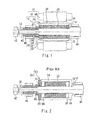
Fig. 1 shows a cross-sectional view of an electric motor having a rotor according to a first embodiment of the present invention; -
Fig. 2 shows a comparative example of a rotor according the prior art; -
Fig. 3 shows a cross-sectional view illustrating a principal part of an electric-motor assistedsupercharger 60 according to a second embodiment of the present invention; -
Fig. 4 is a view for explaining a phenomenon that arises in a case where the rotor of the electric-motor assisted supercharger according the second embodiment is replaced with the rotor of the comparative example shown inFig. 2 ; -
Fig. 5 is a view for explaining a phenomenon that arises in the rotor inside the electric-motor assisted supercharger according to the present invention; and -
Fig. 6 _shows a cross-sectional view of a rotor according to a third embodiment of the present invention. -
Fig. 1 is a view illustrating the configuration of anelectric motor 11 having arotor 10 as a first embodiment of the present invention. Therotor 10 shown inFig. 1 includes ashaft 12. Theshaft 12 includes abase portion 14, a large-diameter portion 16, and a small-diameter portion 18 which have different outer diameters to each other. Thebase portion 14, the large-diameter portion 16, and the small-diameter portion 18 have cylindrical shapes that are mutually concentric. Areference face 20 is formed at a stepped portion at which the shape of theshaft 12 changes between the large-diameter portion 16 and the small-diameter portion 18. More specifically, thereference face 20 is an end face of the large-diameter portion 16 that is exposed at the outer side of the small-diameter portion 18, and has an annular shape in the present embodiment. - A
rotor sub-assembly 22 is mounted on theshaft 12. Therotor sub-assembly 22 includes a ring-shapedmember 24. The ring-shapedmember 24 is a cylindrical member in which both ends are open. Anannular magnet 26 is housed inside the ring-shapedmember 24. Themagnet 26 has an inner diameter that is slightly larger than the large-diameter portion 16 of theshaft 12, and has an outer diameter that is approximately equal to the inner diameter of the ring-shapedmember 24. Themagnet 26 is inserted into the ring-shapedmember 24 by press-fitting. In the present embodiment, themagnet 26 is a member that rotates at a high speed together with theshaft 12. By performing the above described press-fitting, a force in a contraction direction that opposes a centrifugal force at the time of high-speed rotation can be applied to themagnet 26, and thus the breaking strength of themagnet 26 can be enhanced. - An end-
plate 28 is disposed on the side of one end of the magnet 26 (the side of the small-diameter portion 18 inFig. 1 ). The end-plate 28 includes a fixingportion 30 and a positioning portion 32. The fixingportion 30 has an inner diameter that is approximately equal to the large-diameter portion 16 of theshaft 12, and an outer diameter that is approximately equal to the inner diameter of the ring-shapedmember 24, and is inserted into the ring-shapedmember 24 by press-fitting. - The positioning portion 32 is formed integrally with the fixing
portion 30, and has an inner diameter that is approximately equal to the small-diameter portion 18 of theshaft 12. Because of the difference between the inner diameter of the fixingportion 30 and the inner diameter of the positioning portion 32, a face that opposes thereference face 20 of theshaft 12 is formed in the positioning portion 32. Hereunder, this face is referred to as "opposingface 34". Further, a face of the positioning portion 32 on an opposite side to the opposingface 34 is referred to as "pressure receiving face 36". - On the opposite side to the end-
plate 28, therotor sub-assembly 22 includes a second end-plate 38 which is provided so that themagnet 26 is sandwiched between the second end-plate 38 and the end-plate 28. The second end-plate 38 has an inner diameter that is approximately equal to the large-diameter portion 16 of theshaft 12, and an outer diameter that is approximately equal to the inner diameter of the ring-shapedmember 24, and is inserted into the ring-shapedmember 24 by press-fitting. - The end-
plate 28 and the second end-plate 38 each come in contact with an axial end face of themagnet 26, and apply a moderate compressive load to themagnet 26. The breaking strength of themagnet 26 is enhanced by receiving the moderate compressive load. In this respect also, the configuration of the present embodiment enhances the breaking strength of themagnet 26. - The
rotor sub-assembly 22 is mounted on theshaft 12 in a state in which themagnet 26, the end-plate 28 and the second end-plate 38 have been press-fitted into the ring-shapedmember 24. At such time, the small-diameter portion 18 and the large-diameter portion 16 of theshaft 12 are inserted inside the end-plate 28 and the second end-plate 38 by mating sockets and spigots. Because the inner diameter of themagnet 26 is slightly larger than the external shape of the large-diameter portion 16 as described above, a slight clearance is secured between theshaft 12 and themagnet 26. According to this configuration, it is possible to avoid a situation in which stress is applied to themagnet 26 from theshaft 12 in the same direction as a centrifugal force that arises during rotation, and thus a loss of the breaking strength of themagnet 26 can be prevented. - The relative position between the
shaft 12 and therotor sub-assembly 22 is determined by thereference face 20 of theshaft 12 coming in contact with the opposingface 34 of the end-plate 28. In this state, a bearingspacer 40 having the same outer diameter as thebase portion 14 is mounted on the small-diameter portion 18 of theshaft 12. Further, anut 42 is fastened onto theshaft 12 at a stage when all of the components that should be mounted on theshaft 12 have been mounted. The present embodiment is configured so that a fastening force generated by the nut 42 (indicated by broken-line arrows inFig. 1 ) reaches one end of the bearingspacer 40. The fastening force is transmitted to thepressure receiving face 36 of the end-plate 28 through the bearingspacer 40. Consequently, when thenut 42 is fastened onto theshaft 12, therotor sub-assembly 22 can be fixed on theshaft 12 in an accurate positional relationship in which the opposingface 34 contacts thereference face 20. - As shown in
Fig. 1 , theshaft 12 is rotatably held bybearings base portion 14 and the bearingspacer 40, respectively. Further, astator 48 of the electric motor is disposed at the outer circumference of therotor sub-assembly 22. - As described above, the end face of the end-
plate 28 comes in contact with the end face of themagnet 26 in the present embodiment. Therefore, the positional relationship between themagnet 26 and theshaft 12 can also be accurately determined by accurately determining the positional relationship between the end-plate 28 and theshaft 12. Furthermore, if the positional relationship between themagnet 26 and theshaft 12 is accurately determined, the positional relationship between themagnet 26 and thestator 48 can also be accurately determined. Therefore, according to the present embodiment, theelectric motor 11 can be realized in which the relative position of themagnet 26 and thestator 48 is determined with a high level of accuracy. - In the present embodiment, because the opposing
face 34 of the positioning portion 32 contacts thereference face 20 of theshaft 12, a fastening force of thenut 42 mainly acts on the positioning portion 32. Therefore, according to this configuration, it is possible to prevent the fastening force of thenut 42 from acting on themagnet 26. - Further, in the present embodiment, the large-
diameter portion 16 of theshaft 12 is a stuff which is intended only to be inserted into therotor sub-assembly 22, thus maintaining an outer diameter which mates by sockets and spigots with the second end-plate 38 over the entire area thereof. In addition, the large-diameter portion 16 is formed to be longer than an "internal length" of therotor sub-assembly 22, that is, the "length from the opposingface 34 of the end-plate 28 to an end face on thebase portion 14 side of the second end-plate 38" of therotor sub-assembly 22. Therefore, in a state in which the relative position between theshaft 12 and therotor sub-assembly 22 is determined, a clearance is reliably secured between the second end-plate 38 and thebase portion 14, and no stress of any kind is applied from outside to the second end-plate 38. According to this configuration, it can be guaranteed that a fastening force of thenut 42 will not be allowed to act on themagnet 26. - The breaking strength of the
magnet 26 decreases if themagnet 26 receives excessive stress in the axial direction. According to the present embodiment, the occurrence of a situation in which the stress that acts on themagnet 26 becomes excessive can be reliably prevented by not allowing a fastening force to act on themagnet 26. According to the present embodiment, in this respect also, themagnet 26 of therotor 10 can be provided with excellent breaking strength. -
Fig. 2 illustrates the configuration of a comparative example (rotor 50) that is used for comparison with therotor 10 shown inFig. 1 . Note that, elements inFig. 2 that are the same as or correspond to constituent elements shown inFig. 1 are assigned the same reference numbers as inFig. 1 and a detailed description of such elements is omitted hereunder. - The
rotor 50 shown inFig. 2 includes arotor sub-assembly 52. Therotor sub-assembly 52 has an end-plate 54 instead of the end-plate 28 shown inFig. 1 . Similarly to the second end-plate 38, the end-plate 54 is press-fitted into the ring-shapedmember 24 so as to be completely housed inside the ring-shapedmember 24. - The
rotor sub-assembly 52 also includes afirst spacer 56 on the side of one end of the ring-shaped member 24 (side of the small-diameter portion 18 inFig. 2 ), and asecond spacer 58 on the side of the other end of the ring-shaped member 24 (side of thebase portion 14 inFig. 2 ). Thefirst spacer 56 and thesecond spacer 58 each contact against an end portion of the ring-shapedmember 24, and are provided so as not to interfere with the end-plate 54 and the second end-plate 38. - Assembly of the
rotor 50 is carried out according to the following procedure. - The
second spacer 58 has an inner diameter that is approximately equal to the large-diameter portion 16 of theshaft 12, and is mounted to theshaft 12 by mating sockets and spigots. In this stage, thesecond spacer 58 is assembled on theshaft 12 so as to contact against the end face of thebase portion 14. - The
magnet 26, the end-plate 54 and the second end-plate 38 are assembled in the ring-shapedmember 24 by press-fitting. Next, theshaft 12 is inserted into the respective centers of themagnet 26, the end-plate 54 and the second end-plate 38 by mating sockets and spigots. Insertion of theshaft 12 proceeds until the end portion of the ring-shapedmember 24 and thesecond spacer 58 come in contact. - Similarly to the
second spacer 58, thefirst spacer 56 is also mounted to theshaft 12 by mating sockets and spigots, so as to contact the end portion of the ring-shapedmember 24. Thefirst spacer 56 is assembled on theshaft 12 so as to contact against the end face of the large-diameter portion 16. - The bearing
spacer 40 is mounted so as to contact against the end portion of thefirst spacer 56. As shown inFig. 2 , thefirst spacer 56 is formed so that the end portion thereof protrudes to the small-diameter portion 18 side from the end face of the large-diameter portion 16. Consequently, in a state in which the bearingspacer 40 contacts thefirst spacer 56, a slight clearance is formed between the bearingspacer 40 and the end portion of the large-diameter portion 16. - After all of the elements have been mounted on the
shaft 12, thenut 42 is fastened at the front end of theshaft 12. The fastening force of thenut 42 is transmitted to the bearingspacer 40. Since a clearance exists between the bearingspacer 40 and the large-diameter portion 16, the fastening force is only transmitted to thefirst spacer 56. The fastening force that is transmitted to thefirst spacer 56 is transmitted via the ring-shapedmember 24 to thesecond spacer 58 without being transmitted to the end-plate 54. As a result, therotor sub-assembly 52 is fixed to theshaft 12 in a state in which thesecond spacer 58 is pressed against thebase portion 14 of theshaft 12. - According to the comparative example (rotor 50) shown in
Fig. 2 , similarly to therotor 10 shown inFig. 1 , the following two effects can be achieved: - 1. The
rotor sub-assembly 52 is fixed to theshaft 12 at the appropriate position in the axial direction. - 2. The fastening force of the
nut 42 is not allowed to act on themagnet 26. - However, the
rotor 50 uses thefirst spacer 56 and thesecond spacer 58 to achieve the above described two effects. In contrast, therotor 10 of the present embodiment can achieve the above described two effects without the use of such spacers. Therefore, according to therotor 10, in comparison to therotor 50, the number of components and the assembling man-hours can be decreased, and the shaft length can also be shortened. Shortening the length of the rotor shaft in an electric motor leads to an improvement in noise characteristics and vibration characteristics. Therefore, according to therotor 10 of the present embodiment, excellent noise and vibration characteristics can be realized in comparison to therotor 50 of the comparative example. - In the above described first embodiment, the
rotor sub-assembly 22 has the second end-plate 38 on the opposite side to the end-plate 28. Similarly to the end-plate 28, the second end-plate 38 fulfills a function of applying a moderate axial stress to themagnet 26, and also fulfills a function of ensuring the concentricity of theshaft 12 at the end portion of therotor sub-assembly 22. However, the second end-plate 38 is not an essential element in the present invention. For example, under a condition in which the shaft length of therotor sub-assembly 22 is sufficiently short, or a condition in which the breaking strength of themagnet 26 is adequate, the second end-plate 38 may be omitted. - Further, although in the above described first embodiment the
magnet 26 having an annular shape is used, the present invention is not limited to thereto. That is, as long as themagnet 26 of therotor 10 can generate a required magnetic field and secure the required rotational balance, and has the required strength, themagnet 26 may consist of a plurality of pieces. - Further, in the above described first embodiment, the length of the large-
diameter portion 16 is longer than the internal length of therotor sub-assembly 22. To prevent stress from acting on themagnet 26 in the axial direction, it is best for the side faces of therotor sub-assembly 22 to be free, and in that respect the configuration of the present embodiment is the best. However, the configuration of the present invention is not limited thereto. That is, a region of theshaft 12 which has an outer diameter that can be inserted into therotor sub-assembly 22 may be equal to or longer than the internal length of therotor sub-assembly 22. - Furthermore, although in the above described first embodiment a member that imparts a fastening force to the
rotor sub-assembly 22 is limited to thenut 42, the present invention is not limited to that structure. That is, a "fastening member" according to the present invention may be any kind of member as long as the member can cause a pressing force in the axial direction to act on therotor sub-assembly 22 when the relevant member is fixed to theshaft 12. -
Fig. 3 is a cross-sectional view illustrating principal part of an electric-motor assistedsupercharger 60 as a second embodiment of the present invention. As shown inFig. 3 , the electric-motor assistedsupercharger 60 of the present embodiment includes theelectric motor 11 shown inFig. 1 , that is, therotor 10 and thestator 48. Hereunder, elements inFig. 3 that are the same as or correspond to elements shown inFig. 1 are assigned the same reference numbers as inFig. 1 and a detailed description of such elements is omitted. - The electric-motor assisted
supercharger 60 of the present embodiment includes acenter housing 62. Aturbine housing 64 is fixed on one side (right side inFig. 3 ) of thecenter housing 62. Acompressor housing 66 is fixed on the other side (left side inFig. 3 ) of thecenter housing 62. - The
rotor 10 is rotatably held by thebearings center housing 62. Further, thestator 48 is housed inside thecenter housing 62 so as to surround therotor sub-assembly 22. - In the present embodiment, the
base portion 14 of theshaft 12 is formed so as to reach the inside of theturbine housing 64. Further, aseal ring 68 for preventing an outflow of oil from thecenter housing 62 to theturbine housing 64 is mounted on thebase portion 14. Lubricating oil circulates inside thecenter housing 62 so that the oil is supplied to thebearings turbine housing 64 can be prevented by theseal ring 68. - A
turbine impeller 70 is housed inside theturbine housing 64. Theturbine impeller 70 is fixed by welding to the end portion of thebase portion 14 of the shaft. Theturbine housing 64 is formed so as to guide exhaust gas of an internal combustion engine that is not illustrated in the drawings to theturbine impeller 70. Theturbine impeller 70 can give a rotational torque to theshaft 12 by receiving energy of the exhaust gas. - In the present embodiment, the small-
diameter portion 18 of theshaft 12 is formed so as to reach the inside of thecompressor housing 66. Further, in the present embodiment, athrust collar 72 is mounted on the small-diameter portion 18 at a position that is adjacent to the bearingspacer 40. A thrust bearing 74 engages with thethrust collar 72. Thethrust collar 72 and the thrust bearing 74 can restrict the axial position of theshaft 12 without restricting rotation of theshaft 12. - A
seal ring collar 76 is mounted adjacent to the thrust collar on the small-diameter portion 18 of theshaft 12. A seal ring 78 that prevents an outflow of oil from thecenter housing 62 to thecompressor housing 66 is mounted on theseal ring collar 76. According to this configuration, the lubricating oil for thebearings center housing 62 can be prevented from leaking out to thecompressor housing 66. - A
compressor impeller 80 is mounted on the small-diameter portion 18 of theshaft 12 so as to be positioned inside thecompressor housing 66. In the present embodiment, thenut 42 is fastened at the end portion of the small-diameter portion 18 so as to fasten together the series of adjacent elements from the bearingspacer 40 to thecompressor impeller 80. According to this configuration, the fastening force of thenut 42 can be caused to act on thepressure receiving face 36 of the end-plate 28 via the series of adjacent elements. - Hereunder, effects obtained by the electric-motor assisted
supercharger 60 will be described referring toFig. 4 andFig. 5 . -
Fig. 4 is a view for explaining a phenomenon that arises in a case where therotor 10 of the electric-motor assistedsupercharger 60 is replaced with therotor 50 of the comparative example shown inFig. 2 . A double folded line denoted byreference numeral 82 inFig. 4 schematically represents a deformation that can arise in theshaft 12 accompanying with the fastening of thenut 42. Further, arrow lines denoted byreference numerals Fig. 4 schematically represent transmission routes of heat that arise in the turbine of the electric-motor assisted supercharger, respectively. - In a case where the
rotor 50 shown inFig. 4 is built into the electric-motor assistedsupercharger 60, the fastening force of thenut 42 is transmitted from the bearingspacer 40 to thefirst spacer 56. The fastening force transmitted to thefirst spacer 56 is further transmitted to thebase portion 14 of theshaft 12 from thesecond spacer 58 located at the turbine-side end portion of therotor sub-assembly 52. When tightening thenut 42 on theshaft 12, a force that is produced as a result of the tightening may be transmitted from one member to another and may act as bending stress at a place to which the force is transmitted. In the case of therotor 50, the bending stress is liable to act at a contact portion between the bearingspacer 40 and thefirst spacer 56 and at a contact portion between thesecond spacer 58 and thebase portion 14. Therefore, when the electric-motor assisted supercharger is constructed using therotor 50, a deformation arises in theshaft 12 on both the turbine side and the compressor side of therotor sub-assembly 52 in some cases, as shown by the double foldedline 82 inFig. 4 . - The influence on vibration and noise characteristics during rotation, which arises due to a deformation of the compressor side can be eliminated by subjecting the
nut 42 to a balance correction process, for example. In contrast, it is difficult to perform such a balance correction process on the turbine side. Therefore, in a case where the electric-motor assistedsupercharger 60 is constructed using therotor 50, characteristics relating to vibration and noise are liable to deteriorate on the turbine side in particular. - In the electric-motor assisted
supercharger 60, a large amount of heat is transmitted from the turbine side to thebase portion 14 of theshaft 12. The magnetic performance of themagnet 26 will decline as themagnet 26 is exposed to heat. Consequently, in the electric-motor assistedsupercharger 60, it is desirable that, as much as possible, heat that is conducted from the turbine side does not reach themagnet 26. - In the
rotor 50, the second end-plate 38 contacts theshaft 12 at the large-diameter portion 16, and thesecond spacer 58 contacts theshaft 12 at thebase portion 14 and the large-diameter portion 16. Consequently, inside therotor 50, as shown by the two arrow lines inFig. 4 , the two routes described below are formed as routes that conduct heat to themagnet 26. Therefore, if the electric-motor assistedsupercharger 60 is formed using therotor 50, it is necessary to implement a countermeasure with regard to heat reaching themagnet 26 on the premise that these two routes exist. - First route 84:
base portion 14 and large-diameter portion 16 →second spacer 58 → ring-shapedmember 24 →magnet 26 - Second route 86: large-
diameter portion 16 → second end-plate 38 →magnet 26 -
Fig. 5 is a view for explaining a phenomenon that arises in therotor 10 inside the electric-motor assistedsupercharger 60 of the present embodiment. A double folded line denoted byreference numeral 88 inFig. 5 schematically represents a deformation that can arise in theshaft 12 accompanying with the fastening of thenut 42. Further, anarrow line 86 indicates a heat conduction route that is the same as thesecond route 86 shown inFig. 4 . - According to the structure of the
rotor 10, the fastening force of thenut 42 is transmitted from the bearingspacer 40 to the positioning portion 32, and is transmitted via the positioning portion 32 to thereference face 20 of theshaft 12. As described, in therotor 10, the place to which a fastening force is transmitted from one member to another, that is, the place to which a force that is attributable to fastening of thenut 42 is transmitted as bending stress to theshaft 12 is gathered to the compressor side of therotor sub-assembly 22 alone. Therefore, as shown by the foldedline 88 inFig. 5 , a deformation of theshaft 12 due to the fastening of thenut 42 arises only in a region on the compressor side relative to therotor sub-assembly 22. - As described above, the influence of a deformation that arises on the compressor side of the
rotor sub-assembly 22 can be eliminated by performing a balancing process on thenut 42. Therefore, according to the configuration of the present embodiment, it is possible to realize the electric-motor assistedsupercharger 60 that has excellent noise and vibration characteristics in comparison to the case of using therotor 50 of the comparative example. - Further, the configuration of the
rotor 10 does not include a spacer that comes in contact with thebase portion 14. Hence, a heat conduction route that reaches themagnet 26 from the turbine side is limited to thesecond route 86 alone. Therefore, according to the configuration of the present embodiment, the thermal environment of themagnet 26 can be improved in comparison to the case using therotor 50 of the comparative example. - Although in the above described second embodiment, a case is described in which the electric-motor assisted
supercharger 60 is constructed using therotor 10, devices which are suitable for use of therotor 10 are not limited to an electric-motor assisted supercharger. For example, therotor 10 is also suitable as an element for constituting an electric supercharger that is constituted by theelectric motor 11 and a compressor. In this case, it is possible to dispose thecompressor impeller 80 on either side of therotor sub-assembly 22. However, because it will be possible to eliminate the influence of a deformation by means of the aforementioned balancing process, thecompressor impeller 80 is preferably disposed between the end-plate 28 and thenut 42, similarly to the configuration in the present embodiment. - Next, a third embodiment of the present invention will be described referring to
Fig. 6. Fig. 6 illustrates the configuration of arotor 90 that is used in the present embodiment. Therotor 90 is suitable as a constituent element of an electric-motor assisted supercharger, and can be used in place of therotor 10 shown inFig. 3 . Note that, elements inFig. 6 that are the same as or correspond to constituent elements of therotor 10 are assigned the same reference numbers as in therotor 10 and a detailed description of such elements is omitted hereunder. - The
rotor 90 shown inFig. 6 has the same configuration as therotor 10 except that the second end-plate 38 is replaced by a turbine-side end-plate 92. The turbine-side end-plate 92 includes a press-fittingmember 94 that is press-fitted into the ring-shapedmember 24, and an annularheat insulating member 96 that is disposed on the inside of the press-fittingmember 94. Theheat insulating member 96 can be made of ceramic, for example, and being configured to be mountable on the large-diameter portion 16 of theshaft 12 by mating sockets and spigots. - According to the configuration of the
rotor 90, a heat route (thesecond route 86 inFig. 5 ) that runs from the large-diameter portion 16 of theshaft 12 to themagnet 26 can be effectively blocked. Therefore, according to the configuration of the present embodiment, an electric-motor assisted supercharger can be realized in which the thermal environment of themagnet 26 is further improved in comparison to the electric-motor assistedsupercharger 60 shown inFig. 3 .
Claims (15)
- A rotor (10; 90) for an electric motor (11), comprising:a ring-shaped rotor sub-assembly (22) including a ring-shaped member (24), a magnet (26) and an first end-plate (28);a shaft (12) that passes through the rotor sub-assembly (22); anda fastening member (42) that is fastened to the shaft (12), and that fixes an axial position of the rotor sub-assembly (22) with respect to the shaft (12);wherein:the shaft (12) includes a step at which a shape of the shaft (12) changes between a small-diameter portion (18) and a large-diameter portion (16), and a reference face (20) that is an end face of the large-diameter portion (16) that is exposed to outside of the small-diameter portion (18);the magnet (26) is disposed between the ring-shaped member (24) and the large-diameter portion (16) of the shaft (12) so as to contact an inner wall of the ring-shaped member (24); andthe first end-plate (28) is mounted to the ring-shaped member (24) so as to oppose a first axial end portion of the magnet (26) and has a positioning portion (32), said positioning portion (32) contacting the reference face (20) at an opposing face (34) that is one face of the positioning portion (32) and receiving a fastening force produced by the fastening member (42) at a pressure receiving face (36) that is another face of the positioning portion (32), and said small-diameter portion (12) is inserted into the positioning portion (32).
- The rotor (10, 90) according to claim 1, wherein the first end-plate (28) is mounted to the ring-shaped member (24) so as to contact the axial end portion of the magnet (26).
- The rotor (10, 90) according to claim 1 or 2, wherein the first end-plate (28) is inserted into the ring-shaped member (24) by press-fitting.
- The rotor (10; 90) according to any one of claims 1 to 3, wherein:said opposing face (34) of the first end-plate (28) is a magnet side face of the positioning portion (32), and said positioning portion (32) contacts the reference face (20) at the magnet side face.
- The rotor (10; 90) according to any of the claims 1 to 4, wherein:an outer diameter of the large-diameter portion (16) of the shaft (12) is maintained at a diameter that is less than an inner diameter of the magnet (26) over a length that is equal to or greater than an internal length of the rotor sub-assembly (22) from the reference face (20); andthe internal length is a length from said opposing face (34) of the positioning portion (32) to an end portion of the rotor sub-assembly (22) on a different side to the positioning portion side.
- The rotor (10, 90) according to any of the claims 1 to 5, wherein:the magnet (26) is inserted into the ring-shaped member (24) by press-fitting
- The rotor (10, 90) according to any of the claims 1 to 6, wherein:the first end-plate (28) has in addition to the positioning portion (32) a fixing portion (30) mounted to the ring-shaped member (24).
- The rotor (10, 90) according to claim 7, wherein:the fixing portion (30) is inserted into the ring-shaped member (24) by press-fitting.
- The rotor (10; 90) according to claim 7 or 8, wherein:the positioning portion (32) is formed integrally with the fixing portion (30), andthe inner diameter of the positioning portion (32) is smaller than the inner diameter of the fixing portion (30) so that the opposing face (34) that opposes the reference face (20) of the shaft (12) is formed in the positioning portion (32).
- The rotor (10; 90) according to any of the claims 1 to 9, wherein:the rotor sub-assembly (22) further comprises a second end-plate (38; 92) that is arranged on the opposite side of the first end-plate (28) and is mounted to the ring-shaped member (24) so as to oppose a second axial end portion of the magnet (26).
- The rotor (10; 90) according to claim 10, wherein:the first end-plate (28) and the second end-plate (38; 92) sandwich the magnet (26) and preferably apply a moderate compressive load to the magnet (26).
- The rotor (10; 90) according to claim 10 or claim 11, wherein:at least of the first end-plate (28) and the second end-plate (38; 92) comprises a heat insulating member (96) at a site that contacts the shaft (12).
- An electric supercharger, comprising:a rotor (10, 90) according to any one of claim 1 to 12;a stator (48) of an electric motor (11) that is disposed at an outer circumference of the rotor sub-assembly (22); anda compressor impeller (80) that is mounted to the shaft (12) so as to be positioned between the pressure receiving face (36) of the positioning portion (32) and the fastening member (42).
- An electric-motor assisted supercharger (60), comprising:an electric supercharger according to claim 13;a turbine impeller (70) that is mounted to the shaft (12) so as to be positioned on an opposite side to the compressor impeller (80) so as to sandwich the rotor sub-assembly (22) therebetween; anda turbine housing (64) that guides exhaust gas of an internal combustion engine to the turbine impeller (70).
- The electric-motor assisted supercharger (60) according to claim 14, wherein:the second end-plate is a turbine-side end-plate (92) that is mounted to the ring-shaped member (24) so as to oppose the second axial end portion of the magnet (26) from the turbine impeller side.
Applications Claiming Priority (1)
| Application Number | Priority Date | Filing Date | Title |
|---|---|---|---|
| JP2014246747A JP6206385B2 (en) | 2014-12-05 | 2014-12-05 | Electric supercharger and electric assist supercharger |
Publications (1)
| Publication Number | Publication Date |
|---|---|
| EP3032708A1 true EP3032708A1 (en) | 2016-06-15 |
Family
ID=54705421
Family Applications (1)
| Application Number | Title | Priority Date | Filing Date |
|---|---|---|---|
| EP15196301.4A Withdrawn EP3032708A1 (en) | 2014-12-05 | 2015-11-25 | Rotor for electric motor, electric supercharger, and electric-motor assisted supercharger |
Country Status (4)
| Country | Link |
|---|---|
| US (1) | US9979245B2 (en) |
| EP (1) | EP3032708A1 (en) |
| JP (1) | JP6206385B2 (en) |
| CN (1) | CN105680595B (en) |
Cited By (2)
| Publication number | Priority date | Publication date | Assignee | Title |
|---|---|---|---|---|
| EP3852241A4 (en) * | 2018-09-14 | 2021-11-03 | Mitsuba Corporation | ELECTRIC MOTOR AND METHOD FOR MANUFACTURING AN ELECTRIC MOTOR |
| US11837935B2 (en) | 2021-02-02 | 2023-12-05 | Black & Decker, Inc. | Canned brushless motor |
Families Citing this family (7)
| Publication number | Priority date | Publication date | Assignee | Title |
|---|---|---|---|---|
| JP6477655B2 (en) * | 2016-10-14 | 2019-03-06 | トヨタ自動車株式会社 | Spacer and electric supercharger |
| CN107120184B (en) * | 2017-06-23 | 2023-06-23 | 黄石炫轺者动力科技有限公司 | Suspension shaft centrifugal supercharger with axial limiting characteristic |
| CN107131049B (en) * | 2017-06-23 | 2023-06-23 | 黄石炫轺者动力科技有限公司 | Suspension shaft centrifugal supercharger suitable for extremely high rotating speed working condition |
| KR102552016B1 (en) * | 2018-03-15 | 2023-07-05 | 현대자동차 주식회사 | Rotor assembly for motor |
| JP7221008B2 (en) | 2018-08-09 | 2023-02-13 | 日機装株式会社 | Canned motor and manufacturing method of canned motor |
| JP7712215B2 (en) * | 2019-05-28 | 2025-07-23 | エルジー イノテック カンパニー リミテッド | motor |
| GB2626579A (en) * | 2023-01-27 | 2024-07-31 | Dyson Technology Ltd | A rotor assembly |
Citations (6)
| Publication number | Priority date | Publication date | Assignee | Title |
|---|---|---|---|---|
| EP0388147A1 (en) * | 1989-03-14 | 1990-09-19 | Hitachi, Ltd. | Turbo-charger with rotary machine |
| JP2006333660A (en) | 2005-05-27 | 2006-12-07 | Toyota Motor Corp | Motor and turbocharger using motor |
| JP2007321675A (en) | 2006-06-01 | 2007-12-13 | Toyota Motor Corp | Rotating shaft structure and electric supercharger |
| JP2008029166A (en) | 2006-07-25 | 2008-02-07 | Toyota Motor Corp | Rotating electric machine cooling structure and electric supercharger |
| JP2008095650A (en) | 2006-10-16 | 2008-04-24 | Toyota Motor Corp | Cooling structure of supercharger with electric motor |
| US20110254399A1 (en) * | 2008-08-20 | 2011-10-20 | Maeick Blanc | Interior Rotor for a Rotary Electrical Machine and Method of Assembling It |
Family Cites Families (10)
| Publication number | Priority date | Publication date | Assignee | Title |
|---|---|---|---|---|
| JPS5743A (en) * | 1980-05-29 | 1982-01-05 | Toshiba Corp | Insulator for prevention of shaft current |
| JPS59230454A (en) * | 1983-06-10 | 1984-12-25 | Fanuc Ltd | Manufacturing method of permanent magnet field rotor |
| US4674178A (en) * | 1985-10-16 | 1987-06-23 | Sundstrand Corporation | Method of fabricating a permanent magnet rotor |
| JPS62254649A (en) * | 1986-04-25 | 1987-11-06 | Isuzu Motors Ltd | Generator for turbocharger |
| KR20020081253A (en) | 2000-01-12 | 2002-10-26 | 몰벨팅 컴패니 | Electric motor with external rotor |
| US6437474B1 (en) * | 2000-04-11 | 2002-08-20 | Ming Tsong Chu | Rotor of synchronous motor |
| EP1748533B1 (en) * | 2005-07-29 | 2010-09-01 | Siemens Aktiengesellschaft | Rotor with permanent magnets for a brushless electric machine |
| JP4671177B2 (en) | 2006-06-02 | 2011-04-13 | 株式会社Ihi | Electric turbocharger |
| JP2011083136A (en) * | 2009-10-08 | 2011-04-21 | Panasonic Corp | Rotor, motor, generator, electric blower, and vacuum cleaner |
| JP5599368B2 (en) | 2011-06-08 | 2014-10-01 | 三菱電機株式会社 | Motor rotor structure of electric turbocharger and its assembly method |
-
2014
- 2014-12-05 JP JP2014246747A patent/JP6206385B2/en not_active Expired - Fee Related
-
2015
- 2015-11-25 EP EP15196301.4A patent/EP3032708A1/en not_active Withdrawn
- 2015-12-03 US US14/957,947 patent/US9979245B2/en not_active Expired - Fee Related
- 2015-12-04 CN CN201510882857.5A patent/CN105680595B/en not_active Expired - Fee Related
Patent Citations (6)
| Publication number | Priority date | Publication date | Assignee | Title |
|---|---|---|---|---|
| EP0388147A1 (en) * | 1989-03-14 | 1990-09-19 | Hitachi, Ltd. | Turbo-charger with rotary machine |
| JP2006333660A (en) | 2005-05-27 | 2006-12-07 | Toyota Motor Corp | Motor and turbocharger using motor |
| JP2007321675A (en) | 2006-06-01 | 2007-12-13 | Toyota Motor Corp | Rotating shaft structure and electric supercharger |
| JP2008029166A (en) | 2006-07-25 | 2008-02-07 | Toyota Motor Corp | Rotating electric machine cooling structure and electric supercharger |
| JP2008095650A (en) | 2006-10-16 | 2008-04-24 | Toyota Motor Corp | Cooling structure of supercharger with electric motor |
| US20110254399A1 (en) * | 2008-08-20 | 2011-10-20 | Maeick Blanc | Interior Rotor for a Rotary Electrical Machine and Method of Assembling It |
Cited By (7)
| Publication number | Priority date | Publication date | Assignee | Title |
|---|---|---|---|---|
| EP3852241A4 (en) * | 2018-09-14 | 2021-11-03 | Mitsuba Corporation | ELECTRIC MOTOR AND METHOD FOR MANUFACTURING AN ELECTRIC MOTOR |
| US11837935B2 (en) | 2021-02-02 | 2023-12-05 | Black & Decker, Inc. | Canned brushless motor |
| US11855521B2 (en) | 2021-02-02 | 2023-12-26 | Black & Decker, Inc. | Brushless DC motor for a body-grip power tool |
| US11870316B2 (en) | 2021-02-02 | 2024-01-09 | Black & Decker, Inc. | Brushless motor including a nested bearing bridge |
| US11876424B2 (en) | 2021-02-02 | 2024-01-16 | Black & Decker Inc. | Compact brushless motor including in-line terminals |
| US11955863B2 (en) | 2021-02-02 | 2024-04-09 | Black & Decker Inc. | Circuit board assembly for compact brushless motor |
| US12261497B2 (en) | 2021-02-02 | 2025-03-25 | Black & Decker Inc. | High-power motor for a body-grip power tool |
Also Published As
| Publication number | Publication date |
|---|---|
| JP2016111806A (en) | 2016-06-20 |
| CN105680595A (en) | 2016-06-15 |
| CN105680595B (en) | 2018-04-27 |
| US20160190882A1 (en) | 2016-06-30 |
| JP6206385B2 (en) | 2017-10-04 |
| US9979245B2 (en) | 2018-05-22 |
Similar Documents
| Publication | Publication Date | Title |
|---|---|---|
| US9979245B2 (en) | Rotor for electric motor, electric supercharger, and electric-motor assisted supercharger | |
| CN102365440B (en) | Bearing unit for turbocharger | |
| US9917482B2 (en) | Hybrid drive module having a rotor secured to a hub via staking | |
| US11418095B2 (en) | Motor assembling method, centering jig, and electric motor | |
| CN109642650B (en) | Rotor carrier and flange assembly | |
| US20140239754A1 (en) | Rotary electric machine | |
| US20110274379A1 (en) | Rotary bearing arrangement | |
| CN103928993B (en) | Motor | |
| JP5757326B2 (en) | Power transmission device | |
| WO2006051934A1 (en) | Surface magnet type motor, surface magnet type motor manufacturing method, and internal combustion engine using the surface magnet type motor | |
| KR20130127454A (en) | Exhaust-gas turbocharger | |
| KR101829715B1 (en) | Bearing housing of an exhaust-gas turbocharger | |
| CN109088491B (en) | Stator of a rotating electrical machine | |
| CN114930052B (en) | Compact torque converter assembly for hybrid power modules | |
| AU2013363696B2 (en) | Sealing arrangement for axially split turbomachines | |
| WO2006112372A1 (en) | Turbosupercharger having rotary electric machine of internal combustion engine | |
| JP6041889B2 (en) | Electric motor and manufacturing method | |
| CN106329868B (en) | Electric motor and electric vehicle and hybrid vehicle having the same | |
| US11584214B2 (en) | Piping, drive train unit comprising such a piping, and installation method | |
| JP6661239B2 (en) | Rotor and motor | |
| CN202652036U (en) | Motor | |
| US11041406B2 (en) | Inlet guide vane assembly of gas turbine and gas turbine | |
| JP7673463B2 (en) | Motor | |
| CN215682014U (en) | Motor and pump device | |
| CN108448798A (en) | Motor assembly and vehicle |
Legal Events
| Date | Code | Title | Description |
|---|---|---|---|
| PUAI | Public reference made under article 153(3) epc to a published international application that has entered the european phase |
Free format text: ORIGINAL CODE: 0009012 |
|
| 17P | Request for examination filed |
Effective date: 20151125 |
|
| AK | Designated contracting states |
Kind code of ref document: A1 Designated state(s): AL AT BE BG CH CY CZ DE DK EE ES FI FR GB GR HR HU IE IS IT LI LT LU LV MC MK MT NL NO PL PT RO RS SE SI SK SM TR |
|
| AX | Request for extension of the european patent |
Extension state: BA ME |
|
| STAA | Information on the status of an ep patent application or granted ep patent |
Free format text: STATUS: EXAMINATION IS IN PROGRESS |
|
| 17Q | First examination report despatched |
Effective date: 20190418 |
|
| GRAP | Despatch of communication of intention to grant a patent |
Free format text: ORIGINAL CODE: EPIDOSNIGR1 |
|
| STAA | Information on the status of an ep patent application or granted ep patent |
Free format text: STATUS: GRANT OF PATENT IS INTENDED |
|
| RIC1 | Information provided on ipc code assigned before grant |
Ipc: H02K 9/22 20060101ALI20201029BHEP Ipc: H02K 1/27 20060101AFI20201029BHEP Ipc: H02K 7/00 20060101ALI20201029BHEP Ipc: F02B 37/10 20060101ALI20201029BHEP Ipc: H02K 5/128 20060101ALI20201029BHEP |
|
| INTG | Intention to grant announced |
Effective date: 20201110 |
|
| STAA | Information on the status of an ep patent application or granted ep patent |
Free format text: STATUS: THE APPLICATION IS DEEMED TO BE WITHDRAWN |
|
| 18D | Application deemed to be withdrawn |
Effective date: 20210323 |