EP3032702A1 - Resonant cavity mode enabled wireless power transfer - Google Patents
Resonant cavity mode enabled wireless power transfer Download PDFInfo
- Publication number
- EP3032702A1 EP3032702A1 EP15195826.1A EP15195826A EP3032702A1 EP 3032702 A1 EP3032702 A1 EP 3032702A1 EP 15195826 A EP15195826 A EP 15195826A EP 3032702 A1 EP3032702 A1 EP 3032702A1
- Authority
- EP
- European Patent Office
- Prior art keywords
- dimensional structure
- receiver
- transmission
- frequency
- transmitter
- Prior art date
- Legal status (The legal status is an assumption and is not a legal conclusion. Google has not performed a legal analysis and makes no representation as to the accuracy of the status listed.)
- Granted
Links
- 238000012546 transfer Methods 0.000 title description 9
- 230000005540 biological transmission Effects 0.000 claims abstract description 58
- 238000000034 method Methods 0.000 claims abstract description 27
- 238000004891 communication Methods 0.000 claims description 7
- 230000007246 mechanism Effects 0.000 claims description 3
- 230000008878 coupling Effects 0.000 description 13
- 238000010168 coupling process Methods 0.000 description 13
- 238000005859 coupling reaction Methods 0.000 description 13
- 238000005259 measurement Methods 0.000 description 9
- 230000001413 cellular effect Effects 0.000 description 5
- 230000005672 electromagnetic field Effects 0.000 description 5
- 239000003990 capacitor Substances 0.000 description 4
- 230000004907 flux Effects 0.000 description 3
- 239000000463 material Substances 0.000 description 3
- 239000000523 sample Substances 0.000 description 3
- RYGMFSIKBFXOCR-UHFFFAOYSA-N Copper Chemical compound [Cu] RYGMFSIKBFXOCR-UHFFFAOYSA-N 0.000 description 2
- 238000005516 engineering process Methods 0.000 description 2
- 230000001965 increasing effect Effects 0.000 description 2
- 230000001939 inductive effect Effects 0.000 description 2
- 238000012986 modification Methods 0.000 description 2
- 230000004048 modification Effects 0.000 description 2
- 239000013598 vector Substances 0.000 description 2
- NIXOWILDQLNWCW-UHFFFAOYSA-N acrylic acid group Chemical group C(C=C)(=O)O NIXOWILDQLNWCW-UHFFFAOYSA-N 0.000 description 1
- XAGFODPZIPBFFR-UHFFFAOYSA-N aluminium Chemical compound [Al] XAGFODPZIPBFFR-UHFFFAOYSA-N 0.000 description 1
- 229910052782 aluminium Inorganic materials 0.000 description 1
- 230000002457 bidirectional effect Effects 0.000 description 1
- 229910052802 copper Inorganic materials 0.000 description 1
- 239000010949 copper Substances 0.000 description 1
- 238000010586 diagram Methods 0.000 description 1
- 230000006870 function Effects 0.000 description 1
- 238000000691 measurement method Methods 0.000 description 1
- 238000012545 processing Methods 0.000 description 1
Images


Classifications
-
- H—ELECTRICITY
- H02—GENERATION; CONVERSION OR DISTRIBUTION OF ELECTRIC POWER
- H02J—CIRCUIT ARRANGEMENTS OR SYSTEMS FOR SUPPLYING OR DISTRIBUTING ELECTRIC POWER; SYSTEMS FOR STORING ELECTRIC ENERGY
- H02J50/00—Circuit arrangements or systems for wireless supply or distribution of electric power
- H02J50/10—Circuit arrangements or systems for wireless supply or distribution of electric power using inductive coupling
- H02J50/12—Circuit arrangements or systems for wireless supply or distribution of electric power using inductive coupling of the resonant type
-
- H—ELECTRICITY
- H02—GENERATION; CONVERSION OR DISTRIBUTION OF ELECTRIC POWER
- H02J—CIRCUIT ARRANGEMENTS OR SYSTEMS FOR SUPPLYING OR DISTRIBUTING ELECTRIC POWER; SYSTEMS FOR STORING ELECTRIC ENERGY
- H02J50/00—Circuit arrangements or systems for wireless supply or distribution of electric power
- H02J50/20—Circuit arrangements or systems for wireless supply or distribution of electric power using microwaves or radio frequency waves
- H02J50/27—Circuit arrangements or systems for wireless supply or distribution of electric power using microwaves or radio frequency waves characterised by the type of receiving antennas, e.g. rectennas
-
- H—ELECTRICITY
- H02—GENERATION; CONVERSION OR DISTRIBUTION OF ELECTRIC POWER
- H02J—CIRCUIT ARRANGEMENTS OR SYSTEMS FOR SUPPLYING OR DISTRIBUTING ELECTRIC POWER; SYSTEMS FOR STORING ELECTRIC ENERGY
- H02J50/00—Circuit arrangements or systems for wireless supply or distribution of electric power
- H02J50/90—Circuit arrangements or systems for wireless supply or distribution of electric power involving detection or optimisation of position, e.g. alignment
Definitions
- the subject matter described herein generally relates to wireless power transfer.
- Wireless power transfer includes wireless techniques for charging of battery powered devices. This wireless charging operates using close proximity between the charging source and the device to be charged.
- WPT technologies such as near-field manetoquasistatic (MQS) WPT and inductive charging are capable of charging a device (e.g., one or two devices) by bringing the device into close proximity with a charging source.
- MQS near-field manetoquasistatic
- This wireless charging technique commonly includes inducing a current in the device to be charged by placing it on or in close proximity with the power source.
- Common examples include charging an electric toothbrush in a charging stand, using a power transfer mat upon which a mobile device is laid, etc.
- broadcast far-field WPT also includes a power source providing a small amount of power for certain device devices at a distance.
- broadcast far-field WPT is capable of transferring power at greater distances, e.g., to a radio frequency identification (RFID) tag.
- RFID radio frequency identification
- this broadcast technique is not efficient in that commonly less than 0.1 % of the source power is provided to the target device.
- regulations often (which vary by jurisdiction) limit the amount of power transferred using such techniques to approximately 100uW. While point-to-point far-field WPT systems maintain higher end-to-end efficiency, these techniques require complex control and tracking mechanisms to maintain a line of sight connection between the power source and the target and are likewise limited in the amount of power that they can deliver.
- an embodiment provides a method of wireless power transmission, comprising: powering a transmitter that produces electromagnetic waves in a three dimensional structure; selecting a transmission frequency that is a resonance frequency for the three dimensional structure; and transmitting, using the transmitter, electromagnetic waves within the three dimensional structure on the transmission frequency selected.
- the selecting comprises in particular selecting two or more transmission frequencies that are resonance frequencies for the three dimensional structure, wherein in particular the two or more frequencies are transmitted at different times.
- the three dimensional structure is in particular a metallic structure, wherein the metallic structure is in particular a substantially complete enclosure.
- the powering comprises powering two or more transmitters
- the transmitting comprises transmitting with the two or more transmitters and the two or more transmitters are placed at different locations within the three dimensional structure.
- the two or more transmitters in particular each transmit on a unique resonance frequency.
- the transmission frequency selected is in particular less than 200Mz.
- Another embodiment provides an apparatus for wireless power transmission, comprising: a power source; and a transmitter operatively coupled to the power source, the transmitter being placed in a three dimensional structure and producing electromagnetic waves; wherein the transmitter transmits at a transmission frequency that is a resonance frequency for the three dimensional structure.
- the transmission frequency comprises in particular two or more transmission frequencies that are resonance frequencies for the three dimensional structure, wherein in particular the two or more frequencies are transmitted at different times.
- the transmitter comprises in particular two or more transmitters placed at different locations within the three dimensional structure, wherein in particular the two or more transmitters each transmit on a unique resonance frequency.
- a further embodiment provides a system for wireless power transmission, comprising: a three dimensional structure; a transmitter placed in the three dimensional structure; a power source that powers the transmitter to produce electromagnetic waves in the three dimensional structure; wherein the transmitter transmits at a transmission frequency that is a resonance frequency for the three dimensional structure.
- the transmission frequency comprises in particular two or more transmission frequencies that are resonance frequencies for the three dimensional structure, wherein in particular the two or more frequencies are transmitted at different times.
- the transmitter comprises in particular two or more transmitters placed at different locations within the three dimensional structure, wherein in particular the two or more transmitters each transmit on a unique resonance frequency.
- Another embodiment provides an apparatus receiving wireless power, comprising: a processor; a memory storing instructions that are executable by the processor; and a receiver that is coupled to the processor; the receiver being tuned to receive wireless power transmitted at a resonance frequency for a three dimensional space.
- the receiver is in particular selected from the group consisting of a coil and a dipole.
- An embodiment provides a technique to wirelessly transmit power anywhere in a confined three dimensional space.
- a transmitter is stimulated at a natural electromagnetic frequency for the space according to the three dimensional structure enclosing or defining the space.
- a metallic structure an embodiment produces low level electromagnetic fields at a resonance frequency for the metallic structure such that power or energy is transmitted efficiently to a coupled receiver placed within the space, i.e., placed with the metallic structure.
- methods are provided to ensure that wireless power is delivered to multiple devices inside the three dimensional structure.
- one or more division techniques are provided such that multiple receivers are powered within the three dimensional structure without taking away power transmission from one another.
- the receivers in the structure that receive the transmitted power may employ a time division multiplexing scheme that allocates time slots where a receiver is tuned into the frequency or power channel of the transmission system.
- the timing of such receiver tuning may be communicated by an out of band communication channel such as via short range wireless communication technologies including BLUETOOTH, WiFi, ZIGBEE, etc.
- the receiver is tuned to the resonant frequency power transmission via tuning the resonant frequency of the receiver (such as a coil or a dipole antenna), for example using a variable capacitor or variable inductor (or switch bank of capacitors or inductors).
- the receiver may also be tuned by using a relay or switch to connect and/or disconnect the coil to the receiver electronics.
- the receiver may also be tuned by controlling the input impedance of the receiver so that it is matched or mismatched to the receiver coil or antenna.
- frequency division multiplexing is used to provide a frequency division multiplexing scheme where power is transferred at different frequencies.
- the various receivers in turn are tuned to receive power at one or more of the frequencies used to transmit the wireless power. This allows the receiving devices to receive power on a particular transmission frequency.
- a technique is provided to increase the volume within the three dimensional space that is capable of transmitting wireless power using a resonant frequency of the structure. For example, for a given resonant frequency of a particular three dimensional structure or space, the resonant frequency will not fully cover all regions of the three dimensional structure with equal WPT efficiency or power. Therefore, an embodiment employs multiple resonant frequencies, either at the same time or at different times, in order to increase the volume of the three dimensional space that is covered. For example, an embodiment may transmit at two or more resonant frequencies using time and/or frequency domain multiplexing or simultaneous transmission via superposition to cover a larger volume of the three dimensional structure with usable wireless power transmission.
- a technique is provided to increase the degrees of freedom with respect to the receiver's orientation to the transmitter. For example, a given resonant frequency for a three dimensional space may power receivers oriented in a particular direction. In order to increase the available receiver orientations, an embodiment uses more than one transmitter such that variously oriented receivers may receive wireless power transmitted on one or more resonant frequencies.
- a receiver is formed as a coil type receiver.
- a coil type receiver may not be desirable.
- an embodiment provides a receiver in the form of a dipole antenna (capacitive antenna) such that a larger range of devices may incorporate the receiver.
- a coupling between the resonant transmission source and the receiving dipole antenna is provided, as is a technique for discovering the coupling there-between.
- FIG. 1(A) illustrates a diagram of an example cavity resonator in the form of a rectangular box 101, although the technique is applicable to arbitrary shapes.
- the receiver 102 has a given length (s) and is located at a position of x 0 , y 0 , z 0 .
- the horizontal and vertical dotted lines in FIG. 1(A) indicate a coil measurement plane and line, respectively.
- FIG. 1(B) illustrates an electromagnetic field distribution for an example resonant frequency emitted by a transmitter, as described more fully in FIG. 2 .
- the field distribution is keyed to a relative magnitude of the field in three parts, i.e., large, small and intermittent.
- the arrows represent the field vectors.
- a given resonant frequency for a given cavity space has a characteristic electromagnetic field that transfers power to a receiver. Depending on the location of the receiver, differing amounts of power are transmitted wirelessly.
- Parameters for maximizing or increasing the efficiency of the WPT between two resonators include the coupling coefficient between the resonators and the quality factors (Q-factors) of each resonator (transmitter and receiver).
- Coupling mode theory (CMT) is used to derive an analytical expression for the coupling coefficient between a cavity resonator and a small receiver, as further described in U.S. Provisional Patent Application Serial No. 62/088,983 .
- CMT is used to posit the coupling of generic, lossless resonators and this may in turn be extended to specific coupling between the example rectangular cavity resonator and the example small coil receiver.
- FIG. 2 (A-B) illustrates an example operating system for resonant wireless power transfer.
- a rectangular aluminum cavity 201 and square coil receiver 202 act as the resonators.
- a hinged door 203 is included. Copper tape may be used on the door jams, although this is not required.
- a 25cm linear probe (transmitter) 204 is attached to the center of the ceiling panel to excite a resonant mode.
- the receiver 202 includes a mall, single turn, square coil that is 7.62cm on each side.
- the receiver 202 is, for example, made of copper wire and is illustrated affixed to an acrylic frame.
- the coil of the receiver 202 terminates in a variable capacitor, which is tuned to the same resonant frequency as the mode of the chamber 201 (stimulated using transmitter 204).
- VNA Vector Network Analyzer
- standard microwave resonator measurement techniques are used to extract system parameters.
- a VNA was used to stimulate a resonant mode of the linear probe 204.
- an extracted resonant frequency of the resonant chamber is 143.09Mz.
- a resonant frequency may be predicted and confirmed via measurement.
- FEM Finite Element Method
- FEM Finite Element Method
- measurements may be conducted to determine the parameters of the receiver coil 202.
- a 2.45cm diameter coil inductively couples into the receiver 202 so that a non-contact measurement can be made with a VNA.
- the capacitor on the coil of the receiver 202 is provided such that its resonant frequency is that of the chamber (143.09Mz).
- the coupling coefficient is a parameter of interest in predicting WPT efficiency
- Two coupled resonators (here chamber/transmitter (201/204) and receiver 202) have resonant symmetric and anti-symmetric modes that occur at two different frequencies, and this difference in these frequencies has a determined relationship.
- the coupling coefficient may be determined.
- the receiver 202 was placed in the chamber on a stand (e.g., PVC stand) at a height (z) of 76cm and moved to positions along a 11 x 10, x - y grid (represented by horizontal plane in dashed line in FIG. 1(A) ).
- a measurement was taken with the VNA via the linear probe 204 (with the door of the chamber 201 closed).
- the intrinsic loss rates of the chamber 201 and receiver 202 may be evaluated.
- the coupling coefficient may be determined given an equation representing the coupled resonators' amplitude evolution over time.
- the WPT provided by such resonance transmission has constant efficiency as a function of distance.
- the measured efficiency remains within 5% - 10% of the maximum expected power transmission.
- 5% - 6% of the loss is due to imperfect impedance match.
- a single resonant mode may provide WPT over more than one dimension (e.g., x and y). However, for a given resonant mode, certain dimension (e.g., z) will not experience wireless power transfer. Accordingly, in an embodiment, more than one resonant mode may be used to provide WPT and/or more than one transmitter 204 may be deployed within the space. This provides greater coverage of the space in terms of WPT efficiency and imparts flexibility to the system in terms of orientation of the receiver(s) and the amount of space that is usable for WPT.
- wireless power systems using resonant WPT may adjust the receiver to adapt the receiver's impedance and resonant frequency.
- the receivers may employ time division multiplexing, e.g., by de-tuning their matching network so that peak power can be provided to individual devices or groups thereof (e.g., those in most need of WPT, as communicated for example by another communication channel).
- more than one mode may be used to achieve a combined magnetic field that covers a large volume of the cavity.
- a three dimensional area of the cavity volume that experiences low WPT efficiency at one mode may be complimented by choosing another mode at which the same three dimensional area has a higher WPT efficiency.
- FIG. 3 illustrates measured WPT efficiency for a coil receiver (similar to receiver 202) in a resonance cavity (similar to chamber 201).
- a coil receiver experiences maximal magnetic flux and thus highest WPT efficiency at an upper region of the chamber, as illustrated in FIG. 3A .
- second mode with a frequency of 193.93Mz, termed TE 012
- the same coil receiver experiences highest WPT efficiency in a middle region of the chamber, as illustrated in FIG. 3B . Therefore, as shown in FIG. 3C , the modes may be used in combination to boost the coverage area of three dimensional space that experiences high efficiency WPT. Given the uniformity of the magnetic flux density over certain regions of the chamber for a given resonance mode, not only may one device be powered over large volumes of the chamber space, but many devices may be powered simultaneously.
- a receiver When a receiver moves about the chamber, it continues to receive WPT in various areas.
- the efficiency of WPT may vary spatially. However, a receiver that is tuned a single time continues to receive WPT at efficiency in excess of 50% throughout much of the chamber.
- the receiver may be dynamically re-tuned in order to increase the WPT efficiency towards the maximum WPT efficiency.
- FIG. 4 illustrates an example implementation where a receiver 402 is coupled to a half wave rectifier via a PCB loop and thereafter to a power management board 405, which is in turn coupled to a rechargeable batter of a cellular phone 406. Approximately 1W of power was driven into the chamber by the transmitter. A voltage data logger may be used to monitor the output voltage of the receiver 402 circuit attached to the cellular phone 406.
- FIG. 5 (A-B) illustrates an example of choosing a resonant frequency and the resultant output at the frequency chosen for the example implementation of FIG. 4 .
- measurements undergo a pronounced decrease in the minimum at a frequency between 190Mz and 195Mz when the receiver is placed within the chamber. Thus, these measurements illustrate that the receiver is receiving WPT using this frequency.
- FIG. 5B illustrates voltage outputs for the example implementation of FIG. 4 .
- a frequency scan across the frequencies of FIG. 5(A) results in an initial spike and, once a single frequency (e.g., an optimal frequency as referenced in FIG. 5(A) ) is chosen, the rectifier voltage received is approximately 6V over the time duration at that transmission frequency. This voltage is in turn fed to the rechargeable battery of the cellular phone 406 for charging.
- a small dipole antenna may be used.
- a similar analytic expression for predicting a coupling coefficient for a sub-wavelength dipole (i.e., 3.81cm, 5.08cm, and 7.62cm) in a resonance chamber i.e., a chamber such as the rectangular, metallic box described herein.
- This along with the Q-factors, similarly allows for predicting WPT efficiency for the small dipole within various locations of the chamber at a given resonance frequency. Again, it can be demonstrated that for many areas in the chamber, WPT efficiency exceeds 60% for a small dipole, similar to a coil receiver.
- an embodiment then provides a method of wireless power transmission where a transmitter, e.g., transmitter 204, produces electromagnetic waves in a three dimensional structure, e.g., a rectangular metallic structure, under power of a power source.
- a transmitter e.g., transmitter 204
- produces electromagnetic waves in a three dimensional structure e.g., a rectangular metallic structure
- power source powers transmitter at 601 in order to produce electromagnetic waves to be transmitted within the three dimensional structure.
- a frequency scan may be used, which may in turn be aided by analysis of predicted WPT efficiency to select a transmission frequency that is a resonance frequency for the three dimensional structure at 602. This permits the transmitter to transmit electromagnetic waves within the three dimensional structure on the transmission frequency selected at 603.
- the transmission on the resonance frequency may be used by any receiver(s) in the three dimensional structure, e.g., to provide charging to coupled devices such as cell phones, power tools, toys, or any like electronic device.
- Selecting at 602 may include selecting two or more transmission frequencies that are resonance frequencies for the three dimensional structure. For example, the two or more frequencies may be transmitted at different times to provide a greater volume of resonant wave transmission to the three dimensional structure. This selecting may be done using communication between the receiving devices and the transmission devices.
- the metallic rectangular box has been used as an example three dimensional structure, other shapes or materials may be used so long as these are amendable to creation of a resonance wave therein.
- the three dimensional structure may be substantially or completely enclosed, the three dimensional structure may also be discontinuous, e.g., including one or more openings such as windows, etc. It is possible, for example, to establish a suitable resonance structure from many different physical structures, including boxes, partial enclosures, portions of buildings, etc.
- the volume of the three dimensional structure that is covered with high efficiency WPT waves may be increased by transmitting with more than one transmitter and/or at various frequencies.
- the powering at 601 may include powering two or more transmitters
- the transmitting at 602 may include transmitting with the two or more transmitters, where the two or more transmitters are placed at different locations within the three dimensional structure.
- the two or more transmitters may each transmit on a unique resonance frequency.
- an embodiment may adjust the transmission system and/or the receiver(s). For example, at 604 the transmission system may communicate to one or more of the receivers to instruct them to tune in to a particular frequency or de-tune in order to adjust WPT within the system. Likewise, one or more of the receivers may communicate at 604 to the transmission system, e.g., to indicate that they are fully charged, such that another frequency of transmission may be selected, as illustrated by way of example at 605.
- an embodiment may include an apparatus for receiving wireless power.
- a small device such as an RFID tag fitted with an appropriate receiver (coil or dipole) may be powered by received WPT.
- WPT wireless personal area network
- more complex electronic devices including rechargeable batteries may be powered and/or recharged using received WPT, e.g., cellular phones, tablet computing devices, laptop computers, power tools, and other data processing or electrically powered devices or components generally (e.g., rechargeable batteries for vehicles).
- a receiver (coil or dipole) is tuned to receive wireless power transmitted at a resonance frequency for a three dimensional structure at 701.
- the tuning may take a variety of forms from simple tuning and detuning to and from a predetermined frequency in a range or may include more complex tuning, including time domain or frequency domain multiplexing techniques to tune in and out.
- the receiver receives WPT at the resonance frequency at 702.
- an embodiment may cause the apparatus to communicate with the transmission system. For example, if the apparatus determines that a coupled rechargeable battery is charged to a predetermined amount, as illustrated at 703, the apparatus may detune the receiver at 704 such that the apparatus does not continue to draw power from the WPT resonance.
- the receiver may be fixed frequency or tunable to more than one resonance frequency for the three dimensional structure and may tune into a given frequency at various times, e.g., according to predetermined instructions.
- the wireless communication (e.g., using a mechanism such as BLUETOOTH LE or the like) may communicate a variety of information between the receiving apparatus and the transmission system.
- the receiving apparatus may communicate with a transmission system providing the wireless power to the three dimensional structure to inform the transmission system of a charging state, a preferred frequency range, a number of devices in the three dimensional structure, a reception status, etc.
- the transmission system may likewise communicate such information to the receiving device(s).
- aspects may be embodied as a system, method or device. Accordingly, aspects may take the form of an entirely hardware embodiment or an embodiment including software that may all generally be referred to herein as a "circuit,” or "system.”
- non-signal storage device is not a signal, is non-transitory, and “non-transitory” includes all media except signal media.
Abstract
Description
- This application claims priority to U.S. provisional application entitled, "Resonant Cavity Mode Enabled Wireless Power Transfer," having Serial No.
62/088,983, filed December 8, 2014 - The subject matter described herein generally relates to wireless power transfer.
- Wireless power transfer (WPT) includes wireless techniques for charging of battery powered devices. This wireless charging operates using close proximity between the charging source and the device to be charged. For example, WPT technologies such as near-field manetoquasistatic (MQS) WPT and inductive charging are capable of charging a device (e.g., one or two devices) by bringing the device into close proximity with a charging source. This wireless charging technique commonly includes inducing a current in the device to be charged by placing it on or in close proximity with the power source. Common examples include charging an electric toothbrush in a charging stand, using a power transfer mat upon which a mobile device is laid, etc.
- WPT also includes a power source providing a small amount of power for certain device devices at a distance. For example, broadcast far-field WPT is capable of transferring power at greater distances, e.g., to a radio frequency identification (RFID) tag. However, this broadcast technique is not efficient in that commonly less than 0.1 % of the source power is provided to the target device. Moreover, regulations often (which vary by jurisdiction) limit the amount of power transferred using such techniques to approximately 100uW. While point-to-point far-field WPT systems maintain higher end-to-end efficiency, these techniques require complex control and tracking mechanisms to maintain a line of sight connection between the power source and the target and are likewise limited in the amount of power that they can deliver.
- In summary, an embodiment provides a method of wireless power transmission, comprising: powering a transmitter that produces electromagnetic waves in a three dimensional structure; selecting a transmission frequency that is a resonance frequency for the three dimensional structure; and transmitting, using the transmitter, electromagnetic waves within the three dimensional structure on the transmission frequency selected. The selecting comprises in particular selecting two or more transmission frequencies that are resonance frequencies for the three dimensional structure, wherein in particular the two or more frequencies are transmitted at different times. The three dimensional structure is in particular a metallic structure, wherein the metallic structure is in particular a substantially complete enclosure. In particular the powering comprises powering two or more transmitters, the transmitting comprises transmitting with the two or more transmitters and the two or more transmitters are placed at different locations within the three dimensional structure. The two or more transmitters in particular each transmit on a unique resonance frequency. The transmission frequency selected is in particular less than 200Mz.
- Another embodiment provides an apparatus for wireless power transmission, comprising: a power source; and a transmitter operatively coupled to the power source, the transmitter being placed in a three dimensional structure and producing electromagnetic waves; wherein the transmitter transmits at a transmission frequency that is a resonance frequency for the three dimensional structure. The transmission frequency comprises in particular two or more transmission frequencies that are resonance frequencies for the three dimensional structure, wherein in particular the two or more frequencies are transmitted at different times. The transmitter comprises in particular two or more transmitters placed at different locations within the three dimensional structure, wherein in particular the two or more transmitters each transmit on a unique resonance frequency.
- A further embodiment provides a system for wireless power transmission, comprising: a three dimensional structure; a transmitter placed in the three dimensional structure; a power source that powers the transmitter to produce electromagnetic waves in the three dimensional structure; wherein the transmitter transmits at a transmission frequency that is a resonance frequency for the three dimensional structure. The transmission frequency comprises in particular two or more transmission frequencies that are resonance frequencies for the three dimensional structure, wherein in particular the two or more frequencies are transmitted at different times. The transmitter comprises in particular two or more transmitters placed at different locations within the three dimensional structure, wherein in particular the two or more transmitters each transmit on a unique resonance frequency.
- Another embodiment provides an apparatus receiving wireless power, comprising: a processor; a memory storing instructions that are executable by the processor; and a receiver that is coupled to the processor; the receiver being tuned to receive wireless power transmitted at a resonance frequency for a three dimensional space. The receiver is in particular selected from the group consisting of a coil and a dipole.
- For a better understanding of the embodiments, together with other and further features and advantages thereof, reference is made to the following description, taken in conjunction with the accompanying drawings. The scope of the invention will be pointed out in the appended claims
-
-
FIG. 1A illustrates an example three dimensional structure and receiver. -
FIG. 1B illustrates electromagnetic field distribution for an example frequency in an example three dimensional structure. -
FIG. 2A illustrates an example three dimensional structure. -
FIG. 2B illustrates an example receiver. -
FIG. 3 (A-C) illustrates electromagnetic field distribution for example frequencies in an example three dimensional structure. -
FIG. 4 illustrates an example implementation with a cellular phone. -
FIG. 5 (A-B) illustrates example frequency selection and WPT for the example implementation ofFIG. 4 . -
FIG. 6 illustrates an example WPT transmission method. -
FIG. 7 illustrates an example WPT reception method. - It will be readily understood that the components of the embodiments, as generally described and illustrated in the figures herein, may be arranged and designed in a wide variety of different configurations in addition to the described example embodiments. Thus, the following more detailed description of the example embodiments, as represented in the figures, is not intended to limit the scope of the embodiments, as claimed, but is merely representative of example embodiments.
- Reference throughout this specification to "one embodiment" or "an embodiment" (or the like) means that a particular feature, structure, or characteristic described in connection with the embodiment is included in at least one embodiment. Thus, the appearance of the phrases "in one embodiment" or "in an embodiment" or the like in various places throughout this specification are not necessarily all referring to the same embodiment.
- Furthermore, the described features, structures, or characteristics may be combined in any suitable manner in one or more embodiments. In the following description, numerous specific details are provided to give a thorough understanding of embodiments. The various embodiments can be practiced without one or more of the specific details, or with other methods, components, materials, et cetera. In other instances, well known structures, materials, or operations are not shown or described in detail to avoid obfuscation.
- An embodiment provides a technique to wirelessly transmit power anywhere in a confined three dimensional space. In an embodiment, a transmitter is stimulated at a natural electromagnetic frequency for the space according to the three dimensional structure enclosing or defining the space. For example, for a metallic structure an embodiment produces low level electromagnetic fields at a resonance frequency for the metallic structure such that power or energy is transmitted efficiently to a coupled receiver placed within the space, i.e., placed with the metallic structure.
- In an embodiment, methods are provided to ensure that wireless power is delivered to multiple devices inside the three dimensional structure. In an embodiment one or more division techniques are provided such that multiple receivers are powered within the three dimensional structure without taking away power transmission from one another. For example, in an embodiment the receivers in the structure that receive the transmitted power may employ a time division multiplexing scheme that allocates time slots where a receiver is tuned into the frequency or power channel of the transmission system. By way of example, the timing of such receiver tuning may be communicated by an out of band communication channel such as via short range wireless communication technologies including BLUETOOTH, WiFi, ZIGBEE, etc. The receiver is tuned to the resonant frequency power transmission via tuning the resonant frequency of the receiver (such as a coil or a dipole antenna), for example using a variable capacitor or variable inductor (or switch bank of capacitors or inductors). The receiver may also be tuned by using a relay or switch to connect and/or disconnect the coil to the receiver electronics. The receiver may also be tuned by controlling the input impedance of the receiver so that it is matched or mismatched to the receiver coil or antenna.
- In an embodiment, frequency division multiplexing is used to provide a frequency division multiplexing scheme where power is transferred at different frequencies. The various receivers in turn are tuned to receive power at one or more of the frequencies used to transmit the wireless power. This allows the receiving devices to receive power on a particular transmission frequency.
- In an embodiment, a technique is provided to increase the volume within the three dimensional space that is capable of transmitting wireless power using a resonant frequency of the structure. For example, for a given resonant frequency of a particular three dimensional structure or space, the resonant frequency will not fully cover all regions of the three dimensional structure with equal WPT efficiency or power. Therefore, an embodiment employs multiple resonant frequencies, either at the same time or at different times, in order to increase the volume of the three dimensional space that is covered. For example, an embodiment may transmit at two or more resonant frequencies using time and/or frequency domain multiplexing or simultaneous transmission via superposition to cover a larger volume of the three dimensional structure with usable wireless power transmission.
- In an embodiment, a technique is provided to increase the degrees of freedom with respect to the receiver's orientation to the transmitter. For example, a given resonant frequency for a three dimensional space may power receivers oriented in a particular direction. In order to increase the available receiver orientations, an embodiment uses more than one transmitter such that variously oriented receivers may receive wireless power transmitted on one or more resonant frequencies.
- In an embodiment, a receiver is formed as a coil type receiver. However, in some implementations a coil type receiver may not be desirable. Accordingly, an embodiment provides a receiver in the form of a dipole antenna (capacitive antenna) such that a larger range of devices may incorporate the receiver. In an embodiment, a coupling between the resonant transmission source and the receiving dipole antenna is provided, as is a technique for discovering the coupling there-between.
- The illustrated example embodiments will be best understood by reference to the figures. The following description is intended only by way of example, and simply illustrates certain example embodiments.
- Referring to
FIG. 1 (A-B), an example system for resonant cavity mode enabled wireless power transfer is illustrated.FIG. 1(A) illustrates a diagram of an example cavity resonator in the form of a rectangular box 101, although the technique is applicable to arbitrary shapes. InFIG. 1(A) , the receiver 102 has a given length (s) and is located at a position of x0, y0, z0. The horizontal and vertical dotted lines inFIG. 1(A) indicate a coil measurement plane and line, respectively. -
FIG. 1(B) illustrates an electromagnetic field distribution for an example resonant frequency emitted by a transmitter, as described more fully inFIG. 2 . The field distribution is keyed to a relative magnitude of the field in three parts, i.e., large, small and intermittent. The arrows represent the field vectors. - As shown in
FIG. 1(B) , a given resonant frequency for a given cavity space has a characteristic electromagnetic field that transfers power to a receiver. Depending on the location of the receiver, differing amounts of power are transmitted wirelessly. - Parameters for maximizing or increasing the efficiency of the WPT between two resonators (here, the transmitter and the receiver) include the coupling coefficient between the resonators and the quality factors (Q-factors) of each resonator (transmitter and receiver). Coupling mode theory (CMT) is used to derive an analytical expression for the coupling coefficient between a cavity resonator and a small receiver, as further described in
U.S. Provisional Patent Application Serial No. 62/088,983 - By knowing the Q-factors and resonant frequencies of the chamber and the receiver coil, along with the coupling coefficient between the two, it is possible to predict the WPT efficiency at any point in the cavity space.
-
FIG. 2 (A-B) illustrates an example operating system for resonant wireless power transfer. Arectangular aluminum cavity 201 andsquare coil receiver 202 act as the resonators. InFIG. 2(A) the cavity dimensions are a = 1.52m, b = 1.42m and c = 1.83m. A hinged door 203 is included. Copper tape may be used on the door jams, although this is not required. - A 25cm linear probe (transmitter) 204 is attached to the center of the ceiling panel to excite a resonant mode. The
receiver 202 includes a mall, single turn, square coil that is 7.62cm on each side. Thereceiver 202 is, for example, made of copper wire and is illustrated affixed to an acrylic frame. The coil of thereceiver 202 terminates in a variable capacitor, which is tuned to the same resonant frequency as the mode of the chamber 201 (stimulated using transmitter 204). - In order to determine the Q-factors and resonant frequencies of the
receiver 202 andchamber 201, a Vector Network Analyzer (VNA) is used to record measurements of each component. Then, standard microwave resonator measurement techniques are used to extract system parameters. In the case of the example chamber ofFIG. 2 (A-B), a VNA was used to stimulate a resonant mode of thelinear probe 204. For example, an extracted resonant frequency of the resonant chamber is 143.09Mz. A resonant frequency may be predicted and confirmed via measurement. In this case, Finite Element Method (FEM) using commercial COMSOL Multiphysics software simulated a frequency of 144.15Mz for theexample chamber 201 ofFIG. 2 (A-B). The average extracted Q-factor for thisexample chamber 201 is 980. - Similarly, measurements may be conducted to determine the parameters of the
receiver coil 202. In this example, a 2.45cm diameter coil (miniloop transformer) inductively couples into thereceiver 202 so that a non-contact measurement can be made with a VNA. The capacitor on the coil of thereceiver 202 is provided such that its resonant frequency is that of the chamber (143.09Mz). - Because the coupling coefficient is a parameter of interest in predicting WPT efficiency, an example of measurement based determination of the couple coefficient is described. Two coupled resonators (here chamber/transmitter (201/204) and receiver 202) have resonant symmetric and anti-symmetric modes that occur at two different frequencies, and this difference in these frequencies has a determined relationship. Thus, by measuring the resonant frequencies of the modes of a full system (here chamber/transmitter (201/204) and receiver 202) using a VNA, the coupling coefficient may be determined. By way of example, the
receiver 202 was placed in the chamber on a stand (e.g., PVC stand) at a height (z) of 76cm and moved to positions along a 11 x 10, x - y grid (represented by horizontal plane in dashed line inFIG. 1(A) ). At each location, a measurement was taken with the VNA via the linear probe 204 (with the door of thechamber 201 closed). Using the previously measured values for the Q-factor of thechamber 201 andreceiver 202, the intrinsic loss rates of thechamber 201 andreceiver 202 may be evaluated. Using the measured magnitude of the difference of the resonant symmetric and anti-symmetric modes, the coupling coefficient may be determined given an equation representing the coupled resonators' amplitude evolution over time. - As has been described, different system characteristics (e.g., structure/cavity shape) impact the volume and/or location within the structure where WPT is maximal. In the example system described in
FIG. 2 (A-B) the peak WPT efficiency at any point within the space is about 72%, with many areas experiencing over 60% efficiency. - The WPT provided by such resonance transmission has constant efficiency as a function of distance. For example, when the
receiver 202 is moved along the z-axis (illustrated inFIG. 2(A) ) with x0, y0 = 65.5cm, as depicted in the vertical dashed line inFIG. 1A , the measured efficiency remains within 5% - 10% of the maximum expected power transmission. Of this, 5% - 6% of the loss is due to imperfect impedance match. - A single resonant mode may provide WPT over more than one dimension (e.g., x and y). However, for a given resonant mode, certain dimension (e.g., z) will not experience wireless power transfer. Accordingly, in an embodiment, more than one resonant mode may be used to provide WPT and/or more than one
transmitter 204 may be deployed within the space. This provides greater coverage of the space in terms of WPT efficiency and imparts flexibility to the system in terms of orientation of the receiver(s) and the amount of space that is usable for WPT. - Additionally, some receiver orientations will experience magnetic flux and a coupling coefficient that varies spatially, even with multiple modes. Therefore, in practice wireless power systems using resonant WPT may adjust the receiver to adapt the receiver's impedance and resonant frequency. Moreover, in some situations the receivers may employ time division multiplexing, e.g., by de-tuning their matching network so that peak power can be provided to individual devices or groups thereof (e.g., those in most need of WPT, as communicated for example by another communication channel).
- Since there is no one mode that provides a field having the same magnitude and direction for WPT that is everywhere in the cavity space, more than one mode may be used to achieve a combined magnetic field that covers a large volume of the cavity. By choosing more than one mode, a three dimensional area of the cavity volume that experiences low WPT efficiency at one mode may be complimented by choosing another mode at which the same three dimensional area has a higher WPT efficiency.
- By way of example,
FIG. 3 (A-C) illustrates measured WPT efficiency for a coil receiver (similar to receiver 202) in a resonance cavity (similar to chamber 201). As illustrated, in a first mode (with a frequency of 132.76Mz, termed TE011), a coil receiver experiences maximal magnetic flux and thus highest WPT efficiency at an upper region of the chamber, as illustrated inFIG. 3A . In contrast, as second mode (with a frequency of 193.93Mz, termed TE012), the same coil receiver experiences highest WPT efficiency in a middle region of the chamber, as illustrated inFIG. 3B . Therefore, as shown inFIG. 3C , the modes may be used in combination to boost the coverage area of three dimensional space that experiences high efficiency WPT. Given the uniformity of the magnetic flux density over certain regions of the chamber for a given resonance mode, not only may one device be powered over large volumes of the chamber space, but many devices may be powered simultaneously. - When a receiver moves about the chamber, it continues to receive WPT in various areas. The efficiency of WPT may vary spatially. However, a receiver that is tuned a single time continues to receive WPT at efficiency in excess of 50% throughout much of the chamber. The receiver may be dynamically re-tuned in order to increase the WPT efficiency towards the maximum WPT efficiency.
-
FIG. 4 illustrates an example implementation where areceiver 402 is coupled to a half wave rectifier via a PCB loop and thereafter to apower management board 405, which is in turn coupled to a rechargeable batter of acellular phone 406. Approximately 1W of power was driven into the chamber by the transmitter. A voltage data logger may be used to monitor the output voltage of thereceiver 402 circuit attached to thecellular phone 406. -
FIG. 5 (A-B) illustrates an example of choosing a resonant frequency and the resultant output at the frequency chosen for the example implementation ofFIG. 4 . InFIG. 5(A) , |S11| measurements undergo a pronounced decrease in the minimum at a frequency between 190Mz and 195Mz when the receiver is placed within the chamber. Thus, these measurements illustrate that the receiver is receiving WPT using this frequency. -
FIG. 5B illustrates voltage outputs for the example implementation ofFIG. 4 . As shown inFIG. 5B , a frequency scan across the frequencies ofFIG. 5(A) results in an initial spike and, once a single frequency (e.g., an optimal frequency as referenced inFIG. 5(A) ) is chosen, the rectifier voltage received is approximately 6V over the time duration at that transmission frequency. This voltage is in turn fed to the rechargeable battery of thecellular phone 406 for charging. - Although a coil (single loop) receiver was used in the example implementation of
FIG. 4 , a small dipole antenna may be used. For example, a similar analytic expression for predicting a coupling coefficient for a sub-wavelength dipole (i.e., 3.81cm, 5.08cm, and 7.62cm) in a resonance chamber (i.e., a chamber such as the rectangular, metallic box described herein) was developed. This, along with the Q-factors, similarly allows for predicting WPT efficiency for the small dipole within various locations of the chamber at a given resonance frequency. Again, it can be demonstrated that for many areas in the chamber, WPT efficiency exceeds 60% for a small dipole, similar to a coil receiver. - Referring now to
FIG. 6 , an embodiment then provides a method of wireless power transmission where a transmitter, e.g.,transmitter 204, produces electromagnetic waves in a three dimensional structure, e.g., a rectangular metallic structure, under power of a power source. Thus, power source powers transmitter at 601 in order to produce electromagnetic waves to be transmitted within the three dimensional structure. - A frequency scan may be used, which may in turn be aided by analysis of predicted WPT efficiency to select a transmission frequency that is a resonance frequency for the three dimensional structure at 602. This permits the transmitter to transmit electromagnetic waves within the three dimensional structure on the transmission frequency selected at 603. The transmission on the resonance frequency may be used by any receiver(s) in the three dimensional structure, e.g., to provide charging to coupled devices such as cell phones, power tools, toys, or any like electronic device.
- Selecting at 602 may include selecting two or more transmission frequencies that are resonance frequencies for the three dimensional structure. For example, the two or more frequencies may be transmitted at different times to provide a greater volume of resonant wave transmission to the three dimensional structure. This selecting may be done using communication between the receiving devices and the transmission devices.
- It is worth noting that while the metallic rectangular box has been used as an example three dimensional structure, other shapes or materials may be used so long as these are amendable to creation of a resonance wave therein. Moreover, while the three dimensional structure may be substantially or completely enclosed, the three dimensional structure may also be discontinuous, e.g., including one or more openings such as windows, etc. It is possible, for example, to establish a suitable resonance structure from many different physical structures, including boxes, partial enclosures, portions of buildings, etc.
- The volume of the three dimensional structure that is covered with high efficiency WPT waves may be increased by transmitting with more than one transmitter and/or at various frequencies. For example, the powering at 601 may include powering two or more transmitters, and the transmitting at 602 may include transmitting with the two or more transmitters, where the two or more transmitters are placed at different locations within the three dimensional structure. In addition, the two or more transmitters may each transmit on a unique resonance frequency.
- If the receiver device(s) and the transmission system engage in communication, either unidirectional or bidirectional, an embodiment may adjust the transmission system and/or the receiver(s). For example, at 604 the transmission system may communicate to one or more of the receivers to instruct them to tune in to a particular frequency or de-tune in order to adjust WPT within the system. Likewise, one or more of the receivers may communicate at 604 to the transmission system, e.g., to indicate that they are fully charged, such that another frequency of transmission may be selected, as illustrated by way of example at 605.
- Turning to
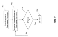
FIG. 7 , an embodiment may include an apparatus for receiving wireless power. For example, a small device such as an RFID tag fitted with an appropriate receiver (coil or dipole) may be powered by received WPT. Likewise, more complex electronic devices including rechargeable batteries may be powered and/or recharged using received WPT, e.g., cellular phones, tablet computing devices, laptop computers, power tools, and other data processing or electrically powered devices or components generally (e.g., rechargeable batteries for vehicles). - In an embodiment a receiver (coil or dipole) is tuned to receive wireless power transmitted at a resonance frequency for a three dimensional structure at 701. The tuning may take a variety of forms from simple tuning and detuning to and from a predetermined frequency in a range or may include more complex tuning, including time domain or frequency domain multiplexing techniques to tune in and out.
- Once the receiver is tuned at 701, the receiver (and any coupled apparatus or component) receives WPT at the resonance frequency at 702. As time progresses, an embodiment may cause the apparatus to communicate with the transmission system. For example, if the apparatus determines that a coupled rechargeable battery is charged to a predetermined amount, as illustrated at 703, the apparatus may detune the receiver at 704 such that the apparatus does not continue to draw power from the WPT resonance.
- The receiver may be fixed frequency or tunable to more than one resonance frequency for the three dimensional structure and may tune into a given frequency at various times, e.g., according to predetermined instructions. The wireless communication (e.g., using a mechanism such as BLUETOOTH LE or the like) may communicate a variety of information between the receiving apparatus and the transmission system. For example, the receiving apparatus may communicate with a transmission system providing the wireless power to the three dimensional structure to inform the transmission system of a charging state, a preferred frequency range, a number of devices in the three dimensional structure, a reception status, etc. As will be understood, the transmission system may likewise communicate such information to the receiving device(s).
- Various aspects may be embodied as a system, method or device. Accordingly, aspects may take the form of an entirely hardware embodiment or an embodiment including software that may all generally be referred to herein as a "circuit," or "system."
- While specific blocks are used in the figures, and a particular ordering of blocks and elements has been illustrated, these are non-limiting examples. In certain contexts, two or more blocks or elements may be combined, a block or element may be split into two or more blocks or elements, or certain blocks or elements may be reordered or re-organized as appropriate, as the explicit illustrated examples are used only for descriptive purposes and are not to be construed as limiting.
- As used herein, the singular "a" and "an" may be construed as including the plural "one or more" unless clearly indicated otherwise. In the context of this document, a non-signal storage device is not a signal, is non-transitory, and "non-transitory" includes all media except signal media.
- This disclosure has been presented for purposes of illustration and description but is not intended to be exhaustive or limiting. The example embodiments were chosen and described in order to explain principles and practical application, and to enable others to understand the disclosure for various embodiments with various modifications as are suited to the particular use contemplated.
- Thus, although illustrative example embodiments have been described herein with reference to the accompanying figures, this description is not limiting and that various other changes and modifications may be affected therein without departing from the scope or spirit of the disclosure.
Claims (15)
- A method of wireless power transmission, comprising:powering a transmitter that produces electromagnetic waves in a three dimensional structure;selecting a transmission frequency that is a resonance frequency for the three dimensional structure; andtransmitting, using the transmitter, electromagnetic waves within the three dimensional structure on the transmission frequency selected.
- The method of claim 1, wherein the selecting comprises selecting two or more transmission frequencies that are resonance frequencies for the three dimensional structure.
- The method of claim 1, wherein the three dimensional structure is substantially enclosed.
- The method of claim 1, wherein the three dimensional structure is a metallic structure.
- The method of claim 1, wherein:the powering comprises powering two or more transmitters;the transmitting comprises transmitting with the two or more transmitters; andthe two or more transmitters are placed at different locations within the three dimensional structure.
- An apparatus for wireless power transmission, comprising:a power source; anda transmitter operatively coupled to the power source, the transmitter being placed in a three dimensional structure and producing electromagnetic waves;wherein the transmitter transmits at a transmission frequency that is a resonance frequency for the three dimensional structure.
- The apparatus of claim 6, wherein the transmission frequency comprises two or more transmission frequencies that are resonance frequencies for the three dimensional structure.
- The apparatus of claim 6, wherein:the transmitter comprises two or more transmitters placed at different locations within the three dimensional structure.
- A system for wireless power transmission, comprising:a three dimensional structure;a transmitter placed in the three dimensional structure;a power source that powers the transmitter to produce electromagnetic waves in the three dimensional structure;wherein the transmitter transmits at a transmission frequency that is a resonance frequency for the three dimensional structure.
- The system of claim 9, wherein the transmission frequency comprises two or more transmission frequencies that are resonance frequencies for the three dimensional structure.
- The system of claim 9, wherein:the transmitter comprises two or more transmitters placed at different locations within the three dimensional structure.
- An apparatus receiving wireless power, comprising:a processor;a memory storing instructions that are executable by the processor; anda receiver that is coupled to the processor;the receiver being tuned to receive wireless power transmitted at a resonance frequency for a three dimensional structure.
- The apparatus of claim 12, wherein the receiver is tunable to more than one resonance frequency for the three dimensional structure.
- The apparatus of claim 13, wherein the processor executes instructions to tune the receiver to a particular resonance frequency.
- The apparatus of claim 13, further comprising:a rechargeable battery coupled to the receiver; anda wirelesses communication mechanism;wherein the apparatus communicates with a transmission system providing the wireless power to the three dimensional structure using a resonant frequency, wherein in particular the apparatus communicates at least a charging state to the transmission system.
Applications Claiming Priority (1)
| Application Number | Priority Date | Filing Date | Title |
|---|---|---|---|
| US201462088983P | 2014-12-08 | 2014-12-08 |
Publications (2)
| Publication Number | Publication Date |
|---|---|
| EP3032702A1 true EP3032702A1 (en) | 2016-06-15 |
| EP3032702B1 EP3032702B1 (en) | 2020-07-08 |
Family
ID=54703822
Family Applications (1)
| Application Number | Title | Priority Date | Filing Date |
|---|---|---|---|
| EP15195826.1A Active EP3032702B1 (en) | 2014-12-08 | 2015-11-23 | Resonant cavity mode enabled wireless power transfer |
Country Status (2)
| Country | Link |
|---|---|
| US (1) | US10707685B2 (en) |
| EP (1) | EP3032702B1 (en) |
Families Citing this family (5)
| Publication number | Priority date | Publication date | Assignee | Title |
|---|---|---|---|---|
| JP6782953B2 (en) * | 2016-04-01 | 2020-11-11 | 国立大学法人豊橋技術科学大学 | Wireless power transmission system |
| JP6973781B2 (en) * | 2017-08-28 | 2021-12-01 | 国立大学法人豊橋技術科学大学 | Wireless power transmission system |
| US11289946B2 (en) * | 2019-04-08 | 2022-03-29 | Purdue Research Foundation | Method and system of uniform wireless power distribution within a chamber |
| CN111146870B (en) * | 2019-12-03 | 2021-07-06 | 电子科技大学 | Device and method for wireless energy transmission based on non-radiative metal gate cavity |
| WO2022168401A1 (en) * | 2021-02-02 | 2022-08-11 | 株式会社村田製作所 | Wireless power transmission system and resonance frequency adjustment unit for wireless power transmission system |
Citations (5)
| Publication number | Priority date | Publication date | Assignee | Title |
|---|---|---|---|---|
| US20110133569A1 (en) * | 2009-12-04 | 2011-06-09 | Electronics And Telecommunications Research Institute | Wireless power transmission device and wireless power reception device |
| US20120280575A1 (en) * | 2011-05-04 | 2012-11-08 | Samsung Electronics Co., Ltd. | Wireless power transmission and reception system |
| EP2736206A1 (en) * | 2011-07-20 | 2014-05-28 | LG Electronics Inc. | Two-way communication using wireless power signal |
| US20140203657A1 (en) * | 2013-01-22 | 2014-07-24 | Samsung Electronics Co., Ltd. | Wireless power transmission apparatus and wireless power transmission method |
| EP2808972A1 (en) * | 2013-05-27 | 2014-12-03 | LG Electronics, Inc. | Wireless power transmitter and wireless power transfer method thereof |
Family Cites Families (59)
| Publication number | Priority date | Publication date | Assignee | Title |
|---|---|---|---|---|
| US20030192053A1 (en) * | 1997-02-19 | 2003-10-09 | Next Level Communications, Inc. | Method and apparatus for transmitting wireless signals over media |
| JP4661900B2 (en) * | 2008-04-17 | 2011-03-30 | ソニー株式会社 | Wireless communication apparatus, power supply method, program, and wireless communication system |
| US8299652B2 (en) * | 2008-08-20 | 2012-10-30 | Intel Corporation | Wireless power transfer apparatus and method thereof |
| US9530555B2 (en) * | 2011-03-29 | 2016-12-27 | Triune Systems, LLC | Wireless power transmittal |
| US20110184842A1 (en) * | 2010-01-28 | 2011-07-28 | Roger D Melen | Energy transfer systems and methods for mobile vehicles |
| JP2011223739A (en) * | 2010-04-09 | 2011-11-04 | Sony Corp | Power supply device, power reception device, and wireless power supply system |
| KR101193939B1 (en) * | 2010-06-21 | 2012-10-24 | 김용남 | Wireless power transfer apparatus |
| US9379780B2 (en) * | 2010-12-16 | 2016-06-28 | Qualcomm Incorporated | Wireless energy transfer and continuous radio station signal coexistence |
| CN103348563A (en) * | 2011-02-17 | 2013-10-09 | 松下电器产业株式会社 | Power transmitting apparatus, power receiving apparatus, and power transmitting method |
| KR101859191B1 (en) * | 2011-03-23 | 2018-05-18 | 삼성전자주식회사 | Method and apparatus for controlling wireless power transmission and reception, and wireless power transmission system |
| JP5338851B2 (en) * | 2011-05-23 | 2013-11-13 | 株式会社デンソー | Power transmission / reception system for vehicles |
| US9948145B2 (en) * | 2011-07-08 | 2018-04-17 | Witricity Corporation | Wireless power transfer for a seat-vest-helmet system |
| US9162691B2 (en) * | 2012-04-27 | 2015-10-20 | Transportation Technology Center, Inc. | System and method for detecting broken rail and occupied track from a railway vehicle |
| EP2845290B1 (en) * | 2012-05-03 | 2018-08-29 | Powermat Technologies Ltd. | System and method for triggering power transfer across an inductive power coupling and non resonant transmission |
| US20150155738A1 (en) * | 2013-05-10 | 2015-06-04 | DvineWave Inc. | Wireless power distribution system for law enforcement equipment |
| US9130397B2 (en) * | 2013-05-10 | 2015-09-08 | Energous Corporation | Wireless charging and powering of electronic devices in a vehicle |
| US9793758B2 (en) * | 2014-05-23 | 2017-10-17 | Energous Corporation | Enhanced transmitter using frequency control for wireless power transmission |
| US20140354221A1 (en) * | 2013-05-10 | 2014-12-04 | DvineWave Inc. | Antenna arrangement for pocket-forming |
| US9859756B2 (en) * | 2012-07-06 | 2018-01-02 | Energous Corporation | Transmittersand methods for adjusting wireless power transmission based on information from receivers |
| US10211680B2 (en) * | 2013-07-19 | 2019-02-19 | Energous Corporation | Method for 3 dimensional pocket-forming |
| US20140375253A1 (en) * | 2013-06-24 | 2014-12-25 | DvineWave Inc. | Methodology for multiple pocket-forming |
| US9973021B2 (en) * | 2012-07-06 | 2018-05-15 | Energous Corporation | Receivers for wireless power transmission |
| US20140008993A1 (en) * | 2012-07-06 | 2014-01-09 | DvineWave Inc. | Methodology for pocket-forming |
| US10128699B2 (en) * | 2014-07-14 | 2018-11-13 | Energous Corporation | Systems and methods of providing wireless power using receiver device sensor inputs |
| US9843213B2 (en) * | 2013-08-06 | 2017-12-12 | Energous Corporation | Social power sharing for mobile devices based on pocket-forming |
| US10141791B2 (en) * | 2014-05-07 | 2018-11-27 | Energous Corporation | Systems and methods for controlling communications during wireless transmission of power using application programming interfaces |
| US9912199B2 (en) * | 2012-07-06 | 2018-03-06 | Energous Corporation | Receivers for wireless power transmission |
| US9450449B1 (en) * | 2012-07-06 | 2016-09-20 | Energous Corporation | Antenna arrangement for pocket-forming |
| US20150130285A1 (en) * | 2013-05-10 | 2015-05-14 | DvineWave Inc. | Portable transmitter for wireless power transmission |
| US9906065B2 (en) * | 2012-07-06 | 2018-02-27 | Energous Corporation | Systems and methods of transmitting power transmission waves based on signals received at first and second subsets of a transmitter's antenna array |
| US10186913B2 (en) * | 2012-07-06 | 2019-01-22 | Energous Corporation | System and methods for pocket-forming based on constructive and destructive interferences to power one or more wireless power receivers using a wireless power transmitter including a plurality of antennas |
| US20150162751A1 (en) * | 2013-05-10 | 2015-06-11 | DvineWave Inc. | Wireless charging of clothing and smart fabrics |
| US20150015192A1 (en) * | 2013-07-11 | 2015-01-15 | DvineWave Inc. | Wireless tracking pocket-forming |
| US9887739B2 (en) * | 2012-07-06 | 2018-02-06 | Energous Corporation | Systems and methods for wireless power transmission by comparing voltage levels associated with power waves transmitted by antennas of a plurality of antennas of a transmitter to determine appropriate phase adjustments for the power waves |
| US20150001949A1 (en) * | 2013-07-01 | 2015-01-01 | DvineWave Inc. | Hybrid charging method for wireless power transmission based on pocket-forming |
| US10128693B2 (en) * | 2014-07-14 | 2018-11-13 | Energous Corporation | System and method for providing health safety in a wireless power transmission system |
| US10141768B2 (en) * | 2013-06-03 | 2018-11-27 | Energous Corporation | Systems and methods for maximizing wireless power transfer efficiency by instructing a user to change a receiver device's position |
| US9900057B2 (en) * | 2012-07-06 | 2018-02-20 | Energous Corporation | Systems and methods for assigning groups of antenas of a wireless power transmitter to different wireless power receivers, and determining effective phases to use for wirelessly transmitting power using the assigned groups of antennas |
| US9893768B2 (en) * | 2012-07-06 | 2018-02-13 | Energous Corporation | Methodology for multiple pocket-forming |
| US9252628B2 (en) * | 2013-05-10 | 2016-02-02 | Energous Corporation | Laptop computer as a transmitter for wireless charging |
| US10103582B2 (en) * | 2012-07-06 | 2018-10-16 | Energous Corporation | Transmitters for wireless power transmission |
| US9410823B2 (en) * | 2012-07-13 | 2016-08-09 | Qualcomm Incorporated | Systems, methods, and apparatus for detection of metal objects in a predetermined space |
| US9276440B2 (en) * | 2012-09-07 | 2016-03-01 | WIPQTUS Inc. | Multi-mode multi-coupling multi-protocol ubiquitous wireless power transmitter |
| US9419443B2 (en) * | 2013-05-10 | 2016-08-16 | Energous Corporation | Transducer sound arrangement for pocket-forming |
| US9537357B2 (en) * | 2013-05-10 | 2017-01-03 | Energous Corporation | Wireless sound charging methods and systems for game controllers, based on pocket-forming |
| US9866279B2 (en) * | 2013-05-10 | 2018-01-09 | Energous Corporation | Systems and methods for selecting which power transmitter should deliver wireless power to a receiving device in a wireless power delivery network |
| US20150333573A1 (en) * | 2013-05-10 | 2015-11-19 | Energous Corporation | Wireless sound power distribution system for law enforcement equipment |
| US20150318729A1 (en) * | 2013-05-10 | 2015-11-05 | Energous Corporation | Wireless sound tracking pocket-forming |
| US9819230B2 (en) * | 2014-05-07 | 2017-11-14 | Energous Corporation | Enhanced receiver for wireless power transmission |
| US20150333528A1 (en) * | 2013-06-12 | 2015-11-19 | Energous Corporation | Wireless sound powered house |
| US9520054B2 (en) * | 2013-10-07 | 2016-12-13 | Google Inc. | Mobile user interface for smart-home hazard detector configuration |
| US9401977B1 (en) * | 2013-10-28 | 2016-07-26 | David Curtis Gaw | Remote sensing device, system, and method utilizing smartphone hardware components |
| US20160020639A1 (en) * | 2014-07-17 | 2016-01-21 | Pavan Pudipeddi | Methods and systems for simultaneously wirelessly charging portable devices using custom-designed and retro-designed power control and supply assemblies and architectural structures facilitating hands-free operation of the portable devices and interaction therewith |
| KR102349713B1 (en) * | 2014-10-20 | 2022-01-12 | 삼성전자주식회사 | Operation Method of communication channel and Electronic device supporting the same |
| US10075018B2 (en) * | 2014-12-10 | 2018-09-11 | Samsung Electronics Co., Ltd. | Wireless power receiver |
| US10122415B2 (en) * | 2014-12-27 | 2018-11-06 | Energous Corporation | Systems and methods for assigning a set of antennas of a wireless power transmitter to a wireless power receiver based on a location of the wireless power receiver |
| KR20160100755A (en) * | 2015-02-16 | 2016-08-24 | 엘지이노텍 주식회사 | Wireless apparatus and method for transmitting power |
| US9620996B2 (en) * | 2015-04-10 | 2017-04-11 | Ossia Inc. | Wireless charging with multiple power receiving facilities on a wireless device |
| US10462689B2 (en) * | 2015-09-22 | 2019-10-29 | Veniam, Inc. | Systems and methods for monitoring a network of moving things |
-
2015
- 2015-04-28 US US14/698,331 patent/US10707685B2/en active Active
- 2015-11-23 EP EP15195826.1A patent/EP3032702B1/en active Active
Patent Citations (5)
| Publication number | Priority date | Publication date | Assignee | Title |
|---|---|---|---|---|
| US20110133569A1 (en) * | 2009-12-04 | 2011-06-09 | Electronics And Telecommunications Research Institute | Wireless power transmission device and wireless power reception device |
| US20120280575A1 (en) * | 2011-05-04 | 2012-11-08 | Samsung Electronics Co., Ltd. | Wireless power transmission and reception system |
| EP2736206A1 (en) * | 2011-07-20 | 2014-05-28 | LG Electronics Inc. | Two-way communication using wireless power signal |
| US20140203657A1 (en) * | 2013-01-22 | 2014-07-24 | Samsung Electronics Co., Ltd. | Wireless power transmission apparatus and wireless power transmission method |
| EP2808972A1 (en) * | 2013-05-27 | 2014-12-03 | LG Electronics, Inc. | Wireless power transmitter and wireless power transfer method thereof |
Also Published As
| Publication number | Publication date |
|---|---|
| US10707685B2 (en) | 2020-07-07 |
| EP3032702B1 (en) | 2020-07-08 |
| US20160164301A1 (en) | 2016-06-09 |
Similar Documents
| Publication | Publication Date | Title |
|---|---|---|
| EP3032702B1 (en) | Resonant cavity mode enabled wireless power transfer | |
| KR102121919B1 (en) | Apparatus for transferring power | |
| US20190044394A1 (en) | Magnetic power transmission utilizing phased transmitter coil arrays and phased receiver coil arrays | |
| US9496731B2 (en) | Apparatus and method for transmitting wireless power by using resonant coupling and system for the same | |
| US9667085B2 (en) | Wireless charger for electronic device | |
| KR101110325B1 (en) | wireless charging system | |
| KR101168619B1 (en) | Wireless power apparatus and methods | |
| EP2991185B1 (en) | Wireless power transfer apparatus and method thereof | |
| CN110199480A (en) | Loop aerial with integrated proximity sensing | |
| US20140091756A1 (en) | Wireless power transfer | |
| US20160043572A1 (en) | Range adaptation mechanism for wireless power transfer | |
| US20100081379A1 (en) | Wirelessly powered speaker | |
| KR20110135540A (en) | Method and apparatus for receiving wireless power | |
| US11133706B2 (en) | Wireless power transmitter | |
| US20170187250A1 (en) | Electromagnetic wave radiation-based wireless power transmitter and wireless power transfer system using high gain antenna and beam forming and steering technology | |
| KR20150006499A (en) | Wireless charging management server, wireless communication charging apparatus, wireless power charging system, and wireless power charging method | |
| US10819151B2 (en) | Wireless power transmission | |
| KR20130128047A (en) | Antenna altitude control device and system and device for wireless power transmission using the same | |
| US10291067B2 (en) | Computer modeling for resonant power transfer systems | |
| KR102193642B1 (en) | Hybrid wireless power transmission device which enables to transmit resonance power signal and induced power signal simultaneously and hybrid wireless power transmission system including the same | |
| KR102109104B1 (en) | Apparatus for transferring power | |
| KR101515476B1 (en) | Wireless power transfer method inside vehicle using NFC | |
| Visser et al. | Far‐Field RF Energy Transfer and Harvesting | |
| RU141723U1 (en) | WIRELESS CHARGING SYSTEM WITH THE ADDITIONAL CHANNEL OF SIMULTANEOUS DATA EXCHANGE | |
| KR101883684B1 (en) | Apparatus and method for transmitting wireless power using resonant coupling therefor system |
Legal Events
| Date | Code | Title | Description |
|---|---|---|---|
| PUAI | Public reference made under article 153(3) epc to a published international application that has entered the european phase |
Free format text: ORIGINAL CODE: 0009012 |
|
| AK | Designated contracting states |
Kind code of ref document: A1 Designated state(s): AL AT BE BG CH CY CZ DE DK EE ES FI FR GB GR HR HU IE IS IT LI LT LU LV MC MK MT NL NO PL PT RO RS SE SI SK SM TR |
|
| AX | Request for extension of the european patent |
Extension state: BA ME |
|
| STAA | Information on the status of an ep patent application or granted ep patent |
Free format text: STATUS: REQUEST FOR EXAMINATION WAS MADE |
|
| 17P | Request for examination filed |
Effective date: 20161215 |
|
| RBV | Designated contracting states (corrected) |
Designated state(s): AL AT BE BG CH CY CZ DE DK EE ES FI FR GB GR HR HU IE IS IT LI LT LU LV MC MK MT NL NO PL PT RO RS SE SI SK SM TR |
|
| REG | Reference to a national code |
Ref country code: HK Ref legal event code: DE Ref document number: 1224827 Country of ref document: HK |
|
| STAA | Information on the status of an ep patent application or granted ep patent |
Free format text: STATUS: EXAMINATION IS IN PROGRESS |
|
| 17Q | First examination report despatched |
Effective date: 20181022 |
|
| GRAP | Despatch of communication of intention to grant a patent |
Free format text: ORIGINAL CODE: EPIDOSNIGR1 |
|
| STAA | Information on the status of an ep patent application or granted ep patent |
Free format text: STATUS: GRANT OF PATENT IS INTENDED |
|
| INTG | Intention to grant announced |
Effective date: 20200127 |
|
| GRAS | Grant fee paid |
Free format text: ORIGINAL CODE: EPIDOSNIGR3 |
|
| GRAA | (expected) grant |
Free format text: ORIGINAL CODE: 0009210 |
|
| STAA | Information on the status of an ep patent application or granted ep patent |
Free format text: STATUS: THE PATENT HAS BEEN GRANTED |
|
| AK | Designated contracting states |
Kind code of ref document: B1 Designated state(s): AL AT BE BG CH CY CZ DE DK EE ES FI FR GB GR HR HU IE IS IT LI LT LU LV MC MK MT NL NO PL PT RO RS SE SI SK SM TR |
|
| REG | Reference to a national code |
Ref country code: CH Ref legal event code: EP Ref country code: AT Ref legal event code: REF Ref document number: 1289515 Country of ref document: AT Kind code of ref document: T Effective date: 20200715 |
|
| REG | Reference to a national code |
Ref country code: DE Ref legal event code: R096 Ref document number: 602015055337 Country of ref document: DE |
|
| REG | Reference to a national code |
Ref country code: IE Ref legal event code: FG4D |
|
| REG | Reference to a national code |
Ref country code: LT Ref legal event code: MG4D |
|
| REG | Reference to a national code |
Ref country code: AT Ref legal event code: MK05 Ref document number: 1289515 Country of ref document: AT Kind code of ref document: T Effective date: 20200708 |
|
| REG | Reference to a national code |
Ref country code: NL Ref legal event code: MP Effective date: 20200708 |
|
| PG25 | Lapsed in a contracting state [announced via postgrant information from national office to epo] |
Ref country code: LT Free format text: LAPSE BECAUSE OF FAILURE TO SUBMIT A TRANSLATION OF THE DESCRIPTION OR TO PAY THE FEE WITHIN THE PRESCRIBED TIME-LIMIT Effective date: 20200708 Ref country code: HR Free format text: LAPSE BECAUSE OF FAILURE TO SUBMIT A TRANSLATION OF THE DESCRIPTION OR TO PAY THE FEE WITHIN THE PRESCRIBED TIME-LIMIT Effective date: 20200708 Ref country code: PT Free format text: LAPSE BECAUSE OF FAILURE TO SUBMIT A TRANSLATION OF THE DESCRIPTION OR TO PAY THE FEE WITHIN THE PRESCRIBED TIME-LIMIT Effective date: 20201109 Ref country code: SE Free format text: LAPSE BECAUSE OF FAILURE TO SUBMIT A TRANSLATION OF THE DESCRIPTION OR TO PAY THE FEE WITHIN THE PRESCRIBED TIME-LIMIT Effective date: 20200708 Ref country code: AT Free format text: LAPSE BECAUSE OF FAILURE TO SUBMIT A TRANSLATION OF THE DESCRIPTION OR TO PAY THE FEE WITHIN THE PRESCRIBED TIME-LIMIT Effective date: 20200708 Ref country code: GR Free format text: LAPSE BECAUSE OF FAILURE TO SUBMIT A TRANSLATION OF THE DESCRIPTION OR TO PAY THE FEE WITHIN THE PRESCRIBED TIME-LIMIT Effective date: 20201009 Ref country code: NO Free format text: LAPSE BECAUSE OF FAILURE TO SUBMIT A TRANSLATION OF THE DESCRIPTION OR TO PAY THE FEE WITHIN THE PRESCRIBED TIME-LIMIT Effective date: 20201008 Ref country code: FI Free format text: LAPSE BECAUSE OF FAILURE TO SUBMIT A TRANSLATION OF THE DESCRIPTION OR TO PAY THE FEE WITHIN THE PRESCRIBED TIME-LIMIT Effective date: 20200708 Ref country code: BG Free format text: LAPSE BECAUSE OF FAILURE TO SUBMIT A TRANSLATION OF THE DESCRIPTION OR TO PAY THE FEE WITHIN THE PRESCRIBED TIME-LIMIT Effective date: 20201008 Ref country code: ES Free format text: LAPSE BECAUSE OF FAILURE TO SUBMIT A TRANSLATION OF THE DESCRIPTION OR TO PAY THE FEE WITHIN THE PRESCRIBED TIME-LIMIT Effective date: 20200708 |
|
| PG25 | Lapsed in a contracting state [announced via postgrant information from national office to epo] |
Ref country code: RS Free format text: LAPSE BECAUSE OF FAILURE TO SUBMIT A TRANSLATION OF THE DESCRIPTION OR TO PAY THE FEE WITHIN THE PRESCRIBED TIME-LIMIT Effective date: 20200708 Ref country code: LV Free format text: LAPSE BECAUSE OF FAILURE TO SUBMIT A TRANSLATION OF THE DESCRIPTION OR TO PAY THE FEE WITHIN THE PRESCRIBED TIME-LIMIT Effective date: 20200708 Ref country code: PL Free format text: LAPSE BECAUSE OF FAILURE TO SUBMIT A TRANSLATION OF THE DESCRIPTION OR TO PAY THE FEE WITHIN THE PRESCRIBED TIME-LIMIT Effective date: 20200708 Ref country code: IS Free format text: LAPSE BECAUSE OF FAILURE TO SUBMIT A TRANSLATION OF THE DESCRIPTION OR TO PAY THE FEE WITHIN THE PRESCRIBED TIME-LIMIT Effective date: 20201108 |
|
| PG25 | Lapsed in a contracting state [announced via postgrant information from national office to epo] |
Ref country code: NL Free format text: LAPSE BECAUSE OF FAILURE TO SUBMIT A TRANSLATION OF THE DESCRIPTION OR TO PAY THE FEE WITHIN THE PRESCRIBED TIME-LIMIT Effective date: 20200708 |
|
| REG | Reference to a national code |
Ref country code: DE Ref legal event code: R097 Ref document number: 602015055337 Country of ref document: DE |
|
| PG25 | Lapsed in a contracting state [announced via postgrant information from national office to epo] |
Ref country code: IT Free format text: LAPSE BECAUSE OF FAILURE TO SUBMIT A TRANSLATION OF THE DESCRIPTION OR TO PAY THE FEE WITHIN THE PRESCRIBED TIME-LIMIT Effective date: 20200708 Ref country code: DK Free format text: LAPSE BECAUSE OF FAILURE TO SUBMIT A TRANSLATION OF THE DESCRIPTION OR TO PAY THE FEE WITHIN THE PRESCRIBED TIME-LIMIT Effective date: 20200708 Ref country code: CZ Free format text: LAPSE BECAUSE OF FAILURE TO SUBMIT A TRANSLATION OF THE DESCRIPTION OR TO PAY THE FEE WITHIN THE PRESCRIBED TIME-LIMIT Effective date: 20200708 Ref country code: EE Free format text: LAPSE BECAUSE OF FAILURE TO SUBMIT A TRANSLATION OF THE DESCRIPTION OR TO PAY THE FEE WITHIN THE PRESCRIBED TIME-LIMIT Effective date: 20200708 Ref country code: RO Free format text: LAPSE BECAUSE OF FAILURE TO SUBMIT A TRANSLATION OF THE DESCRIPTION OR TO PAY THE FEE WITHIN THE PRESCRIBED TIME-LIMIT Effective date: 20200708 Ref country code: SM Free format text: LAPSE BECAUSE OF FAILURE TO SUBMIT A TRANSLATION OF THE DESCRIPTION OR TO PAY THE FEE WITHIN THE PRESCRIBED TIME-LIMIT Effective date: 20200708 |
|
| PLBE | No opposition filed within time limit |
Free format text: ORIGINAL CODE: 0009261 |
|
| STAA | Information on the status of an ep patent application or granted ep patent |
Free format text: STATUS: NO OPPOSITION FILED WITHIN TIME LIMIT |
|
| PG25 | Lapsed in a contracting state [announced via postgrant information from national office to epo] |
Ref country code: AL Free format text: LAPSE BECAUSE OF FAILURE TO SUBMIT A TRANSLATION OF THE DESCRIPTION OR TO PAY THE FEE WITHIN THE PRESCRIBED TIME-LIMIT Effective date: 20200708 |
|
| 26N | No opposition filed |
Effective date: 20210409 |
|
| PG25 | Lapsed in a contracting state [announced via postgrant information from national office to epo] |
Ref country code: MC Free format text: LAPSE BECAUSE OF FAILURE TO SUBMIT A TRANSLATION OF THE DESCRIPTION OR TO PAY THE FEE WITHIN THE PRESCRIBED TIME-LIMIT Effective date: 20200708 Ref country code: SK Free format text: LAPSE BECAUSE OF FAILURE TO SUBMIT A TRANSLATION OF THE DESCRIPTION OR TO PAY THE FEE WITHIN THE PRESCRIBED TIME-LIMIT Effective date: 20200708 |
|
| REG | Reference to a national code |
Ref country code: CH Ref legal event code: PL |
|
| PG25 | Lapsed in a contracting state [announced via postgrant information from national office to epo] |
Ref country code: LU Free format text: LAPSE BECAUSE OF NON-PAYMENT OF DUE FEES Effective date: 20201123 |
|
| REG | Reference to a national code |
Ref country code: BE Ref legal event code: MM Effective date: 20201130 |
|
| PG25 | Lapsed in a contracting state [announced via postgrant information from national office to epo] |
Ref country code: CH Free format text: LAPSE BECAUSE OF NON-PAYMENT OF DUE FEES Effective date: 20201130 Ref country code: LI Free format text: LAPSE BECAUSE OF NON-PAYMENT OF DUE FEES Effective date: 20201130 Ref country code: SI Free format text: LAPSE BECAUSE OF FAILURE TO SUBMIT A TRANSLATION OF THE DESCRIPTION OR TO PAY THE FEE WITHIN THE PRESCRIBED TIME-LIMIT Effective date: 20200708 |
|
| PG25 | Lapsed in a contracting state [announced via postgrant information from national office to epo] |
Ref country code: IE Free format text: LAPSE BECAUSE OF NON-PAYMENT OF DUE FEES Effective date: 20201123 |
|
| PG25 | Lapsed in a contracting state [announced via postgrant information from national office to epo] |
Ref country code: TR Free format text: LAPSE BECAUSE OF FAILURE TO SUBMIT A TRANSLATION OF THE DESCRIPTION OR TO PAY THE FEE WITHIN THE PRESCRIBED TIME-LIMIT Effective date: 20200708 Ref country code: MT Free format text: LAPSE BECAUSE OF FAILURE TO SUBMIT A TRANSLATION OF THE DESCRIPTION OR TO PAY THE FEE WITHIN THE PRESCRIBED TIME-LIMIT Effective date: 20200708 Ref country code: CY Free format text: LAPSE BECAUSE OF FAILURE TO SUBMIT A TRANSLATION OF THE DESCRIPTION OR TO PAY THE FEE WITHIN THE PRESCRIBED TIME-LIMIT Effective date: 20200708 |
|
| PG25 | Lapsed in a contracting state [announced via postgrant information from national office to epo] |
Ref country code: MK Free format text: LAPSE BECAUSE OF FAILURE TO SUBMIT A TRANSLATION OF THE DESCRIPTION OR TO PAY THE FEE WITHIN THE PRESCRIBED TIME-LIMIT Effective date: 20200708 |
|
| PG25 | Lapsed in a contracting state [announced via postgrant information from national office to epo] |
Ref country code: BE Free format text: LAPSE BECAUSE OF NON-PAYMENT OF DUE FEES Effective date: 20201130 |
|
| P01 | Opt-out of the competence of the unified patent court (upc) registered |
Effective date: 20230525 |
|
| PGFP | Annual fee paid to national office [announced via postgrant information from national office to epo] |
Ref country code: GB Payment date: 20231019 Year of fee payment: 9 |
|
| PGFP | Annual fee paid to national office [announced via postgrant information from national office to epo] |
Ref country code: FR Payment date: 20231019 Year of fee payment: 9 Ref country code: DE Payment date: 20231019 Year of fee payment: 9 |