EP3032650B1 - Inscribed polarizer array for polarization diverse applications - Google Patents
Inscribed polarizer array for polarization diverse applications Download PDFInfo
- Publication number
- EP3032650B1 EP3032650B1 EP15199288.0A EP15199288A EP3032650B1 EP 3032650 B1 EP3032650 B1 EP 3032650B1 EP 15199288 A EP15199288 A EP 15199288A EP 3032650 B1 EP3032650 B1 EP 3032650B1
- Authority
- EP
- European Patent Office
- Prior art keywords
- polarizer
- antenna
- elements
- aperture
- antenna system
- Prior art date
- Legal status (The legal status is an assumption and is not a legal conclusion. Google has not performed a legal analysis and makes no representation as to the accuracy of the status listed.)
- Active
Links
Images





Classifications
-
- H—ELECTRICITY
- H01—ELECTRIC ELEMENTS
- H01Q—ANTENNAS, i.e. RADIO AERIALS
- H01Q15/00—Devices for reflection, refraction, diffraction or polarisation of waves radiated from an antenna, e.g. quasi-optical devices
- H01Q15/24—Polarising devices; Polarisation filters
- H01Q15/242—Polarisation converters
-
- H—ELECTRICITY
- H01—ELECTRIC ELEMENTS
- H01Q—ANTENNAS, i.e. RADIO AERIALS
- H01Q15/00—Devices for reflection, refraction, diffraction or polarisation of waves radiated from an antenna, e.g. quasi-optical devices
- H01Q15/24—Polarising devices; Polarisation filters
- H01Q15/242—Polarisation converters
- H01Q15/244—Polarisation converters converting a linear polarised wave into a circular polarised wave
-
- H—ELECTRICITY
- H01—ELECTRIC ELEMENTS
- H01Q—ANTENNAS, i.e. RADIO AERIALS
- H01Q15/00—Devices for reflection, refraction, diffraction or polarisation of waves radiated from an antenna, e.g. quasi-optical devices
- H01Q15/24—Polarising devices; Polarisation filters
- H01Q15/242—Polarisation converters
- H01Q15/246—Polarisation converters rotating the plane of polarisation of a linear polarised wave
-
- H—ELECTRICITY
- H01—ELECTRIC ELEMENTS
- H01Q—ANTENNAS, i.e. RADIO AERIALS
- H01Q21/00—Antenna arrays or systems
- H01Q21/24—Combinations of antenna units polarised in different directions for transmitting or receiving circularly and elliptically polarised waves or waves linearly polarised in any direction
Definitions
- the present disclosure relates generally to antenna arrays and, more particularly, to an apparatus and method for altering the polarization of an antenna array to support specific communications or radar applications for which there is a need to quickly change the intrinsic polarization of the antenna from one polarization sense (such as vertical or right-hand circular) to another (such as horizontal or lefthand circular).
- one polarization sense such as vertical or right-hand circular
- another such as horizontal or lefthand circular
- satellite communications applications require that a particular satellite link use a specific combination of frequency band and polarization for the transmit portion of the link and a different combination of frequency band and polarization for the receive portion of the link. Additionally, satellite communications applications may require that the polarizations for each distinct band be periodically changed or switched to support oppositely polarized satellite transponders, or to counteract ("track-out") relative changes in polarization that may occur as a result of antenna orientation or geo-location.
- Earth station antennas used in airborne operations that operate in the Ka communications band typically need to be capable of switching from Right Hand Circular polarization to Left Hand Circular polarization with little or no input from the operator.
- a typical method for switching the circular polarization of a Ka-band antenna is to bring the circularly polarized transmit and receive signals to the back of the array, and then switch the polarization to the opposite sense using a polarization switch (which tends to be expensive and bulky).
- Another method of switching polarization is to physically "flip" a polarizer mounted on the face of the planar array antenna.
- a substantial increase in package volume is required to support such approach.
- a common practice for altering the polarization of linear polarized reflector antennas is to physically rotate a dual linear polarized horn antenna that is used to feed such reflector antennas, rotating polarization in the process.
- these types of antennas are bulky and exhibit poor efficiency when required to fit in limited volumes such as under radomes mounted on ground vehicles or aircraft.
- Planar antennas on the other hand, can be made with more extreme aspect ratios (length vs. height) to support such packaging challenges.
- a common practice of rotating the linear polarization of this type of antenna is achieved via the use of an Orthomode Transducer (OMT).
- OMT Orthomode Transducer
- CP circular polarization
- WO2010/048174 discloses an antenna system comprising an antenna having an aperture and rotatable polarizer panels for covering said aperture.
- An inscribed polarizer array in accordance with the present disclosure includes one or more polarizing elements rotatable about an axis, and an actuator coupled to the one or more polarizing elements to effect common rotation of the polarizing elements.
- the one or more polarization elements can have, for example, a circular shape, a tear drop, or other shapes.
- the polarizer array is configured for placement relative to a planar radiating aperture to at least partially cover the aperture, thereby inscribing the planar area of the aperture.
- the polarizing array enables change of a polarization state of energy incident on the aperture, while providing a lower cost, light weight, compact device that can effect polarization changes.
- the inscribed polarizer provides increased ohmic efficiency, as losses associated with the OMT or switch are removed as a contributor to poor ohmic efficiency. Further, the requisite planar array feed structure can in many cases be greatly simplified to further improve array efficiency. Further, the present disclosure includes inserts placed in the interstitial regions on the antenna aperture wherein the inserts are configured to match an insertion phase of the at least two polarizers. Said interstitial regions are defined by portions of the aperture uncovered by the polarizer array.
- an antenna system may include one or more polarizers that remain co-planar (or close to coplanar) to a rectangular (non-circular) antenna aperture, the one or more polarizers rotatable around one or more axes normal, or close to normal, relative to the rectilinear planar aperture surface.
- Such geometry may result in "interstitial" uncovered gaps between the rotating polarizers.
- a single-axis polarizer may include a single circular polarizer inscribed (i.e. not fully covering) a square aperture. Due to the different geometries between the aperture and polarizer, "interstitial" uncovered gaps (e.g., uncovered corners of the square) result.
- an antenna system may include two or more coplanar (side-by-side) polarizers that inscribe the antenna aperture.
- an antenna system includes: an antenna having an aperture; and a polarizer array comprising a support structure, at least two polarizer elements arranged relative to the support structure, each of the at least two polarizer elements rotatable about a separate axis, and an actuator coupled to the at least two polarizer elements, the actuator operative to effect common rotation of the at least two polarizer elements, wherein the polarizer array is arranged to at least partially cover the antenna aperture.
- the at least two polarizer elements comprise dissimilar polarizer elements.
- the at least two polarizer elements have different dimensions from one another.
- an area of one of the at least two polarizer elements is different from an area of another of the at least two polarizer elements.
- the at least two polarizer elements comprise circular characteristics.
- the at least two polarizer elements comprise a tear drop shape or a circular shape.
- the actuator effects ganged mechanical rotation of the at least two polarizer elements.
- the actuator comprises at least one of a DC brushless motor, a stepper motor, a timing belt, a chain drive or a gear drive.
- the at least two polarizers comprise a linear-to-circular polarization polarizer or a dichroic linear-to-circular polarization polarizer.
- the at least two polarizers are configured to effect a switching of one sense of circular polarization to another sense of circular polarization.
- the at least two polarizers are configured to effect a twisting of one sense of linear polarization to another sense of linear polarization.
- the at least two polarizers comprise a twist polarizer operative to change a linearly-polarized wave polarized in a first direction to a linearly-polarized wave polarized in a second direction different from the first direction.
- the at least two polarizers comprise meanderline polarizers operative to convert a polarized wave to a circular polarized wave.
- the common rotation comprises synchronized rotation.
- the polarizer array includes a support structure, wherein the at least two polarizer elements mounted on the support structure.
- each polarizer element of the at least two polarizer elements is rotatable about a center axis of the respective polarizer element.
- the non-circular antenna comprises a planar antenna.
- the antenna aperture comprises a prescribed area, and the at least two polarizing elements extend outside the prescribed area.
- the antenna aperture is tapered in a predetermined plane of the planar antenna.
- the antenna system includes a transceiver communicatively coupled to the antenna aperture.
- the at least two polarizers cover at least 83 percent of the surface area of the antenna aperture.
- the antenna aperture has a non-circular shape.
- the antenna aperture has a rectangular shape.
- the at least two polarizers are co-planar.
- an antenna system includes: an antenna including an aperture having a first geometry; and a polarizer array comprising a support structure, at least one polarizer element arranged relative to the support structure, the at least one polarizer element having a second geometry different from the first geometry and rotatable about an axis, and an actuator coupled to the at least one polarizer element, the actuator operative to effect rotation of the at least one polarizer element, wherein the polarizer array is arranged relative to the antenna aperture such that at least a portion of the antenna aperture is uncovered by the at least one polarizer.
- Planar antenna systems which have all elements (both active and passive) in one plane, are often required to fit into relatively small spaces while maintaining key performance characteristics, including high ohmic efficiency and broad band operation.
- a polarization scheme has been devised whereby two or more polarizers (e.g., polarizers having circular characteristics, such as circular polarizers, tear drop polarizers, and the like), each capable of mechanical rotation, are employed to partially cover a fixed/staring rectangular planar array antenna aperture, inscribing the array's rectangular area.
- the inscribed polarizer array in accordance with the present disclosure allows for single-polarized planar array antennas to perform polarization functions that generally require more complicated and more expensive dual-polarized planar array antennas. Further, the inscribed polarizer array enables added functionality when applied to dual-polarized arrays via the addition of tracking linear (V/H and H/V) and switchable circular (RHCP/LHCP, LHCP/RHCP) polarization flexibility, without added microwave polarization control components.
- the term "inscribe” is defined as to not fully cover an area of an object. For example, if a shape (e.g., a first planar shape) is overlaid on a second shape (e.g., a second planar shape), the first shape inscribes the second shape when at least a portion of the second shape is uncovered (exposed) by the first shape).
- a shape e.g., a first planar shape
- a second shape e.g., a second planar shape
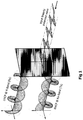
- Polarizers can take on many forms and functions. In frequency spectrums where linear polarization dominates (i.e., Ku-Band), a commonly used polarizer is the twist polarizer, which takes an linearly-polarized input wave that is polarized in one direction and twists it to a differently oriented (but still linear) polarization. Another type of polarizer is the meanderline polarizer as shown in Fig. 1 , which converts an input polarized input wave to circular polarization.
- the inscribed polarizer array 10 includes two or more polarizers 12 (i.e., a polarizer array), such as circular polarizers, that are configured for "ganged" mechanical rotation, e.g., synchronized rotation about an axis, such as a center axis or axis of symetry.
- polarizers 12 i.e., a polarizer array
- circular polarizers such as circular polarizers
- the circular polarizers 12, which convert a signal from a first polarization sense 13a to a second polarization sense 13b, are located just in front of a planar array antenna 14 in which polarization is to be either continuously changed (in the case of tracking linear polarization for Ku-band SATCOM applications) or switched from one polarization state to another (in the case of circular polarization for Ka-band SATCOM applications).
- the planar array antenna 14 feeds a signal to a transceiver 16 for signal processing.
- Fig. 2 The approach illustrated in Fig. 2 in which the polarizers only partially cover the array antenna is counter-intuitive to conventional thinking. More specifically, one having ordinary skill in the art would expect that the configuration shown in Fig. 2 (i.e., where portions of the antenna array are uncovered by the polarizer) would produce unacceptable gain loss and cross-pol. Contrary to such thinking, the partial coverage provided by the inscribed polarizer yields excellent gain and cross-pol performance, despite the uncovered areas of the antenna array.
- a front perspective view of an exemplary inscribed polarizer array 10 in accordance with the present disclosure is illustrated.
- circular meanderline polarizers 12 are employed to (partially) cover a (fixed/staring) rectangular planar array aperture 18a of a planar antenna array 18, "inscribing" the rectangular area.
- the polarizer array 10 may include a support structure 19 ( Fig. 3B ) to which at least two polarizer elements 12 may be mounted. Alternatively, the at least two polarizer elements 12 may be directly mounted on a support structure of a planar antenna 18 as shown in Fig. 3a .
- the actuator 20 may be mounted to the support structure 19 of the polarizer array 10 or to the support structure of the planar antenna 18.
- the extremely low mass of the polarizer array elements 12 allow for the use of a very small, low torque drive actuator.
- Some embodiments may utilize actuators in the form of stepper motors, timing belts, chain drives, gear drives and combinations thereof to support the requisite rotational motion of the polarizer elements 12.
- the actuator 20 may be driven by control circuitry (not shown) to alter an angular orientation of the polarizers 12.
- planar array aperture 18a is only “partially” filled (covered), the embodiment shown in Fig. 3a nevertheless provides high gain efficiency and good cross-pol isolation characteristics.
- a perfect circular polarizer embodiment (covering/inscribing 78.5% of a given square uniformly-excited sub-region and employing low-density phase-matching interstitial inserts via 22) yields a theoretical cross-polarization (cross-pol) isolation of -16 dB (2.7 dB Axial Ratio) and a net peak gain loss (due to polarization and directivity losses) of just -0.5 dB.
- planar aperture 18a is intentionally tapered in the elevation plane, as is often employed in order to suppress elevation side lobes (and meaning that proportionally less power is present in the (uncovered) interstitial regions as compared to the (covered) polarizer regions, then these loss/cross-pol metrics can improve appreciably to ⁇ -0.3 dB net co-polarization (co-pol) gain loss and cross-pol better than -22 dB (1.4 dB AR).
- Fig. 4a shows an embodiment in which teardrop shaped polarizer elements 12a are used to increase the circular polarizer region
- Fig. 4b illustrates an embodiment where over-sized polarizer elements 12b are used (e.g., one or more polarizing elements extend outside an area of the antenna aperture).
- the size (area) of the uncovered regions (i.e., the interstitial regions) between the polarizer elements is reduced, which improves the overall performance (gain efficiency and cross-pol isolation) of the inscribed polarizer array 10.
- Fig. 4c illustrates an embodiment that takes advantage of this design characteristic. More particularly, "dissimilar polarizer elements" 12c and 12d are used (e.g., a larger center polarizer element and smaller polarizer elements arranged adjacent to the larger element, polarizer elements having different dimensions from one another, different surface areas from one another, etc.) and thus the exposed interstitial regions on the outer sections of the array do not have a significant effect on the performance. By increasing the size of the center-most polarizing element 12d, the gain and polarization purity are improved. It is noted, however, that if RF energy is uniformly dispersed on the face of the array aperture, then the advantages of the embodiment shown in Fig. 4c are less dramatic.
- the (rotating) circular polarizers 12 may be in the form of either a "standard" linear-to-CP (circular polarization) polarizer or in the form of a "dichroic" linear-to-CP polarizer.
- the "trace axes" of a single circular polarizing layer can be oriented at either +/- 45 degrees relative to a linear-polarized aperture in order to switch between the desired CP senses.
- a single fixed (rectangular) linear-to-CP polarizer can be affixed to the rectangular radiating aperture 18 and the rotating circular polarizers 12 (CP-to-linear in this case) can be mounted immediately on top of the fixed polarizing layer.
- the interstitial (semi-triangular) sections of the planar array 18 that are not covered by the circular shaped polarizers foam can be covered with appropriate low-density inserts 22, e.g., foam elements, meander-line elements, dielectric elements, etc.
- the addition of the low-density foam 22 and/or meander-line elements in the fixed interstitial regions serves to approximately match the insertion-phase and intermediate polarization of the covered circular regions, thereby providing for improved net coherent gain contributions (for the desired co-polarized signal) from the interstitial regions (albeit at a fixed polarization which only partially matches the desired variable polarization in the covered regions.)
- the polarizer 30 includes a sheet 32 which includes four stacked layers 34a-34d, and an array of resonant structures 36 formed on each of the stacked layers 34a-34d.
- the resonant structures 36 within the array are preferably identical with respect to those on the same layer 34 as well as those in or on the other layers 34.
- the resonant structures 36 in or on each layer 34 are aligned with corresponding resonant structures 36 on any overlying or underlying layer 34. Consequently, the sheet 32 is made up of an array of unit cells 40 with each of the unit cells 40 being represented by a corresponding stack of resonant structures 36 formed in or on the respective layers 34.
- each of the layers 34 includes a layer of dielectric material.
- the resonant structures 36 may be formed of conductive material (e.g., copper) deposited, etched, adhered or otherwise formed on the dielectric material using any conventional technique.
- the resonant structures 36 may be represented by apertures formed in each of the respective sheets. Assume "m" represents the number of layers 34, and m is an integer equal to or greater than one.
- each of the stacked resonant structures 36 in a given unit cell 40 introduces a phase differential of approximately +90°/m to the linearly polarized electromagnetic energy within the first distinct frequency band, with respect to electromagnetic energy which is incident upon and passes through the polarizer 30.
- each of the stacked resonant structures 36 introduces a phase differential of approximately -90°/m to the linearly polarized electromagnetic energy within the second distinct frequency band, with respect to electromagnetic energy incident upon and passing through the polarizer 30.
- electromagnetic energy which passes through a given unit cell 40 consisting of m layers 34 will undergo a phase differential of ⁇ 90°, depending upon the particular frequency band.
- Figs. 7A/7B and 8A/8B show measured Axial Ratio and measured Gain, respectively, for two different frequency bands of operation, for a planar array with varying amounts of fill for the planar array aperture 18a (100%, 85%, and 64%) by the polarizer array 12.
- the inscribed polarizer array 10 in accordance with the present disclosure can be installed in front of an antenna array. Since multiple separate polarization paths do not to be carried, such configuration allows use of a simplified corporate feed network behind the array.
- the polarizing architecture utilized in the inscribed polarizer array 10 eliminates the need for (and losses associated with) a separate mechanically rotated or electronically rotated OMT to achieve tracking linear polarization as the antenna is moved from one location to another. Additionally, the polarizer architecture eliminates the need for (and losses associated with) a separate polarization switch (for switched Circular Polarization), nor does it have any high-power limits (no power-limiting switches or OMT's). In the case of on-the-move antennas that require elevation and azimuth control, the polarizer architecture eliminates the need to bring multiple waveguide channels (dual band and/or dual pol) across the axes of rotation.
- Other application examples benefiting from this invention can include one or more of the following:
Landscapes
- Variable-Direction Aerials And Aerial Arrays (AREA)
- Waveguide Aerials (AREA)
Description
- The present disclosure relates generally to antenna arrays and, more particularly, to an apparatus and method for altering the polarization of an antenna array to support specific communications or radar applications for which there is a need to quickly change the intrinsic polarization of the antenna from one polarization sense (such as vertical or right-hand circular) to another (such as horizontal or lefthand circular).
- To support full-duplex, 2-way communication, many satellite communications applications require that a particular satellite link use a specific combination of frequency band and polarization for the transmit portion of the link and a different combination of frequency band and polarization for the receive portion of the link. Additionally, satellite communications applications may require that the polarizations for each distinct band be periodically changed or switched to support oppositely polarized satellite transponders, or to counteract ("track-out") relative changes in polarization that may occur as a result of antenna orientation or geo-location. Earth station antennas used in airborne operations that operate in the Ka communications band, for instance, typically need to be capable of switching from Right Hand Circular polarization to Left Hand Circular polarization with little or no input from the operator.
- A typical method for switching the circular polarization of a Ka-band antenna is to bring the circularly polarized transmit and receive signals to the back of the array, and then switch the polarization to the opposite sense using a polarization switch (which tends to be expensive and bulky). Another method of switching polarization is to physically "flip" a polarizer mounted on the face of the planar array antenna. However, a substantial increase in package volume is required to support such approach.
- A common practice for altering the polarization of linear polarized reflector antennas is to physically rotate a dual linear polarized horn antenna that is used to feed such reflector antennas, rotating polarization in the process. However these types of antennas are bulky and exhibit poor efficiency when required to fit in limited volumes such as under radomes mounted on ground vehicles or aircraft. Planar antennas on the other hand, can be made with more extreme aspect ratios (length vs. height) to support such packaging challenges. A common practice of rotating the linear polarization of this type of antenna is achieved via the use of an Orthomode Transducer (OMT). In the case of circularly polarized antennas and some linear polarized antennas, a separate polarization switch is often employed to rotate one sense of circular to the other (e.g., left hand circular to right hand circular). Both approaches, however, have their drawbacks since OMT's and polarization switches tend to be large in size, heavy, expensive, and in many cases, suffer from high ohmic losses.
- Another method of switching circular polarization (CP) is to physically "flip" a low-loss linear-to-CP polarizer mounted on the face of the planar array antenna. However, a substantial increase in package volume is required to support such an approach.
-
WO2010/048174 discloses an antenna system comprising an antenna having an aperture and rotatable polarizer panels for covering said aperture. - An inscribed polarizer array in accordance with the present disclosure includes one or more polarizing elements rotatable about an axis, and an actuator coupled to the one or more polarizing elements to effect common rotation of the polarizing elements. The one or more polarization elements can have, for example, a circular shape, a tear drop, or other shapes. The polarizer array is configured for placement relative to a planar radiating aperture to at least partially cover the aperture, thereby inscribing the planar area of the aperture. The polarizing array enables change of a polarization state of energy incident on the aperture, while providing a lower cost, light weight, compact device that can effect polarization changes. An advantage of the inscribed polarizer is that it provides increased ohmic efficiency, as losses associated with the OMT or switch are removed as a contributor to poor ohmic efficiency. Further, the requisite planar array feed structure can in many cases be greatly simplified to further improve array efficiency. Further, the present disclosure includes inserts placed in the interstitial regions on the antenna aperture wherein the inserts are configured to match an insertion phase of the at least two polarizers. Said interstitial regions are defined by portions of the aperture uncovered by the polarizer array.
- For example, an antenna system may include one or more polarizers that remain co-planar (or close to coplanar) to a rectangular (non-circular) antenna aperture, the one or more polarizers rotatable around one or more axes normal, or close to normal, relative to the rectilinear planar aperture surface. Such geometry may result in "interstitial" uncovered gaps between the rotating polarizers.
- In one embodiment, a single-axis polarizer may include a single circular polarizer inscribed (i.e. not fully covering) a square aperture. Due to the different geometries between the aperture and polarizer, "interstitial" uncovered gaps (e.g., uncovered corners of the square) result. In another embodiment, an antenna system may include two or more coplanar (side-by-side) polarizers that inscribe the antenna aperture.
- According to one aspect of the invention, an antenna system includes: an antenna having an aperture; and a polarizer array comprising a support structure, at least two polarizer elements arranged relative to the support structure, each of the at least two polarizer elements rotatable about a separate axis, and an actuator coupled to the at least two polarizer elements, the actuator operative to effect common rotation of the at least two polarizer elements, wherein the polarizer array is arranged to at least partially cover the antenna aperture.
- In one embodiment, the at least two polarizer elements comprise dissimilar polarizer elements.
- In one embodiment, the at least two polarizer elements have different dimensions from one another.
- In one embodiment, an area of one of the at least two polarizer elements is different from an area of another of the at least two polarizer elements.
- In one embodiment, the at least two polarizer elements comprise circular characteristics.
- In one embodiment, the at least two polarizer elements comprise a tear drop shape or a circular shape.
- In one embodiment, the actuator effects ganged mechanical rotation of the at least two polarizer elements.
- In one embodiment, the actuator comprises at least one of a DC brushless motor, a stepper motor, a timing belt, a chain drive or a gear drive.
- In one embodiment, the at least two polarizers comprise a linear-to-circular polarization polarizer or a dichroic linear-to-circular polarization polarizer.
- In one embodiment, the at least two polarizers are configured to effect a switching of one sense of circular polarization to another sense of circular polarization.
- In one embodiment, the at least two polarizers are configured to effect a twisting of one sense of linear polarization to another sense of linear polarization.
- In one embodiment, the at least two polarizers comprise a twist polarizer operative to change a linearly-polarized wave polarized in a first direction to a linearly-polarized wave polarized in a second direction different from the first direction.
- In one embodiment, the at least two polarizers comprise meanderline polarizers operative to convert a polarized wave to a circular polarized wave.
- In one embodiment, the common rotation comprises synchronized rotation.
- In one embodiment, the polarizer array includes a support structure, wherein the at least two polarizer elements mounted on the support structure.
- In one embodiment, each polarizer element of the at least two polarizer elements is rotatable about a center axis of the respective polarizer element.
- In one embodiment, the non-circular antenna comprises a planar antenna.
- In one embodiment, the antenna aperture comprises a prescribed area, and the at least two polarizing elements extend outside the prescribed area.
- In one embodiment, the antenna aperture is tapered in a predetermined plane of the planar antenna.
- In one embodiment, the antenna system includes a transceiver communicatively coupled to the antenna aperture.
- In one embodiment, the at least two polarizers cover at least 83 percent of the surface area of the antenna aperture.
- In one embodiment, the antenna aperture has a non-circular shape.
- In one embodiment, the antenna aperture has a rectangular shape.
- In one embodiment, the at least two polarizers are co-planar.
- According to one aspect of the invention, an antenna system includes: an antenna including an aperture having a first geometry; and a polarizer array comprising a support structure, at least one polarizer element arranged relative to the support structure, the at least one polarizer element having a second geometry different from the first geometry and rotatable about an axis, and an actuator coupled to the at least one polarizer element, the actuator operative to effect rotation of the at least one polarizer element, wherein the polarizer array is arranged relative to the antenna aperture such that at least a portion of the antenna aperture is uncovered by the at least one polarizer.
- To the accomplishment of the foregoing and related ends, the invention, then, comprises the features hereinafter fully described and particularly pointed out in the claims. The following description and the annexed drawings set forth in detail certain illustrative embodiments of the invention. These embodiments are indicative, however, of but a few of the various ways in which the principles of the invention may be employed. Other objects, advantages and novel features of the invention will become apparent from the following detailed description of the invention when considered in conjunction with the drawings.
- In the annexed drawings, like references indicate like parts or features.
-
Fig. 1 is a functional diagram of an exemplary polarizer that may be used in an inscribed polarizer array in accordance with the present disclosure. -
Fig. 2 is a block diagram of an exemplary inscribed polarizer array in accordance with the present disclosure. -
Fig. 3a is a perspective view of a generic planar antenna array employing an inscribed polarizer in accordance with the present disclosure. -
Fig. 3b is a perspective view showing the inscribed polarizer and support structure in accordance with the present disclosure. -
Fig. 4a illustrates an inscribed polarizer array employing tear-drop shape polarizer elements. -
Fig. 4b illustrates an inscribed polarizer array employing over-sized polarizer elements. -
Fig. 4c illustrates an inscribed polarizer array employing one large polarizing element and two smaller polarizing elements. -
Fig. 5 is a block diagram of an exemplary inscribed polarizer array employing dielectric elements in the interstitial space in accordance with the present disclosure. -
Fig. 6 is an exploded view of an exemplary dual-band dichroic polarizer that may be used in an inscribed polarizer array in accordance with the present disclosure. -
Figs. 7A and 7B are graphs showing axial ratio performance vs. different aperture coverage. -
Figs. 8A and 8B are graphs showing gain performance vs. different aperture coverage. - Planar antenna systems, which have all elements (both active and passive) in one plane, are often required to fit into relatively small spaces while maintaining key performance characteristics, including high ohmic efficiency and broad band operation. To achieve such performance and still provide polarization diversity in a compact package, a polarization scheme has been devised whereby two or more polarizers (e.g., polarizers having circular characteristics, such as circular polarizers, tear drop polarizers, and the like), each capable of mechanical rotation, are employed to partially cover a fixed/staring rectangular planar array antenna aperture, inscribing the array's rectangular area. The simple rotation of these polarizers on the face of the array can either effect the switching of one sense of circular polarization to another or the twisting and alignment of one sense of linear polarization to another, obviating the need for a heavy and expensive polarization switch or orthomode transducer, and in the process potentially simplifying the internal complexity of the array.
- The inscribed polarizer array in accordance with the present disclosure allows for single-polarized planar array antennas to perform polarization functions that generally require more complicated and more expensive dual-polarized planar array antennas. Further, the inscribed polarizer array enables added functionality when applied to dual-polarized arrays via the addition of tracking linear (V/H and H/V) and switchable circular (RHCP/LHCP, LHCP/RHCP) polarization flexibility, without added microwave polarization control components.
- As used herein, the term "inscribe" is defined as to not fully cover an area of an object. For example, if a shape (e.g., a first planar shape) is overlaid on a second shape (e.g., a second planar shape), the first shape inscribes the second shape when at least a portion of the second shape is uncovered (exposed) by the first shape).
- Polarizers can take on many forms and functions. In frequency spectrums where linear polarization dominates (i.e., Ku-Band), a commonly used polarizer is the twist polarizer, which takes an linearly-polarized input wave that is polarized in one direction and twists it to a differently oriented (but still linear) polarization. Another type of polarizer is the meanderline polarizer as shown in
Fig. 1 , which converts an input polarized input wave to circular polarization. - Referring now to
Fig. 2 , illustrated is a block diagram of an exemplary inscribedpolarizer array 10 in accordance with the present disclosure. The inscribedpolarizer array 10 includes two or more polarizers 12 (i.e., a polarizer array), such as circular polarizers, that are configured for "ganged" mechanical rotation, e.g., synchronized rotation about an axis, such as a center axis or axis of symetry. Thecircular polarizers 12, which convert a signal from afirst polarization sense 13a to asecond polarization sense 13b, are located just in front of aplanar array antenna 14 in which polarization is to be either continuously changed (in the case of tracking linear polarization for Ku-band SATCOM applications) or switched from one polarization state to another (in the case of circular polarization for Ka-band SATCOM applications). Theplanar array antenna 14 feeds a signal to atransceiver 16 for signal processing. - The approach illustrated in
Fig. 2 in which the polarizers only partially cover the array antenna is counter-intuitive to conventional thinking. More specifically, one having ordinary skill in the art would expect that the configuration shown inFig. 2 (i.e., where portions of the antenna array are uncovered by the polarizer) would produce unacceptable gain loss and cross-pol. Contrary to such thinking, the partial coverage provided by the inscribed polarizer yields excellent gain and cross-pol performance, despite the uncovered areas of the antenna array. - With additional reference to
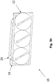
Figs. 3a and3b , a front perspective view of an exemplary inscribedpolarizer array 10 in accordance with the present disclosure is illustrated. In theexemplary polarizer array 10circular meanderline polarizers 12 are employed to (partially) cover a (fixed/staring) rectangularplanar array aperture 18a of aplanar antenna array 18, "inscribing" the rectangular area. Thepolarizer array 10 may include a support structure 19 (Fig. 3B ) to which at least twopolarizer elements 12 may be mounted. Alternatively, the at least twopolarizer elements 12 may be directly mounted on a support structure of aplanar antenna 18 as shown inFig. 3a . - One or
more actuators 20, such as a motor (e.g., a DC brushless motor), are operatively coupled to thepolarizers 12 to effect ganged rotation thereof. Theactuator 20 may be mounted to thesupport structure 19 of thepolarizer array 10 or to the support structure of theplanar antenna 18. The extremely low mass of thepolarizer array elements 12 allow for the use of a very small, low torque drive actuator. Some embodiments may utilize actuators in the form of stepper motors, timing belts, chain drives, gear drives and combinations thereof to support the requisite rotational motion of thepolarizer elements 12. Theactuator 20 may be driven by control circuitry (not shown) to alter an angular orientation of thepolarizers 12. - Although the
planar array aperture 18a is only "partially" filled (covered), the embodiment shown inFig. 3a nevertheless provides high gain efficiency and good cross-pol isolation characteristics. Theoretically, a perfect circular polarizer embodiment (covering/inscribing 78.5% of a given square uniformly-excited sub-region and employing low-density phase-matching interstitial inserts via 22) yields a theoretical cross-polarization (cross-pol) isolation of -16 dB (2.7 dB Axial Ratio) and a net peak gain loss (due to polarization and directivity losses) of just -0.5 dB. If theplanar aperture 18a is intentionally tapered in the elevation plane, as is often employed in order to suppress elevation side lobes (and meaning that proportionally less power is present in the (uncovered) interstitial regions as compared to the (covered) polarizer regions, then these loss/cross-pol metrics can improve appreciably to < -0.3 dB net co-polarization (co-pol) gain loss and cross-pol better than -22 dB (1.4 dB AR). - In addition, small increases in the circular polarizer region (e.g., extending some distance outside the circular boundary) can dramatically improve both the co-pol loss and cross-pol isolation characteristics. More particularly, system performance can be enhanced by reducing the area of the aperture that is not within the polarizer region.
Fig. 4a shows an embodiment in which teardrop shapedpolarizer elements 12a are used to increase the circular polarizer region, whileFig. 4b illustrates an embodiment whereover-sized polarizer elements 12b are used (e.g., one or more polarizing elements extend outside an area of the antenna aperture). In the embodiments ofFigs. 4a and 4b , the size (area) of the uncovered regions (i.e., the interstitial regions) between the polarizer elements is reduced, which improves the overall performance (gain efficiency and cross-pol isolation) of the inscribedpolarizer array 10. - Often, antennas are tapered in the elevation plane to suppress elevation sidelobes focus more energy in the center of array aperture (less energy impinges on the interstitial regions).
Fig. 4c illustrates an embodiment that takes advantage of this design characteristic. More particularly, "dissimilar polarizer elements" 12c and 12d are used (e.g., a larger center polarizer element and smaller polarizer elements arranged adjacent to the larger element, polarizer elements having different dimensions from one another, different surface areas from one another, etc.) and thus the exposed interstitial regions on the outer sections of the array do not have a significant effect on the performance. By increasing the size of the center-mostpolarizing element 12d, the gain and polarization purity are improved. It is noted, however, that if RF energy is uniformly dispersed on the face of the array aperture, then the advantages of the embodiment shown inFig. 4c are less dramatic. - The (rotating)
circular polarizers 12 may be in the form of either a "standard" linear-to-CP (circular polarization) polarizer or in the form of a "dichroic" linear-to-CP polarizer. For CP operation, the "trace axes" of a single circular polarizing layer can be oriented at either +/- 45 degrees relative to a linear-polarized aperture in order to switch between the desired CP senses. In the case of a tracking-linear variant (e.g., at Ku-Band), a single fixed (rectangular) linear-to-CP polarizer can be affixed to therectangular radiating aperture 18 and the rotating circular polarizers 12 (CP-to-linear in this case) can be mounted immediately on top of the fixed polarizing layer. - With additional reference to
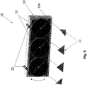
Fig. 5 , the interstitial (semi-triangular) sections of theplanar array 18 that are not covered by the circular shaped polarizers foam can be covered with appropriate low-density inserts 22, e.g., foam elements, meander-line elements, dielectric elements, etc. The addition of the low-density foam 22 and/or meander-line elements in the fixed interstitial regions serves to approximately match the insertion-phase and intermediate polarization of the covered circular regions, thereby providing for improved net coherent gain contributions (for the desired co-polarized signal) from the interstitial regions (albeit at a fixed polarization which only partially matches the desired variable polarization in the covered regions.) - With reference to
Fig. 6 , an exemplary dichroic linear-to-CP polarizer 30 is illustrated that may be used in the inscribedpolarizer array 10 in accordance with the present disclosure. Thepolarizer 30 includes asheet 32 which includes fourstacked layers 34a-34d, and an array ofresonant structures 36 formed on each of thestacked layers 34a-34d. Theresonant structures 36 within the array are preferably identical with respect to those on thesame layer 34 as well as those in or on the other layers 34. Theresonant structures 36 in or on eachlayer 34 are aligned with correspondingresonant structures 36 on any overlying orunderlying layer 34. Consequently, thesheet 32 is made up of an array ofunit cells 40 with each of theunit cells 40 being represented by a corresponding stack ofresonant structures 36 formed in or on the respective layers 34. - In the
exemplary polarizer 30, each of thelayers 34 includes a layer of dielectric material. Theresonant structures 36 may be formed of conductive material (e.g., copper) deposited, etched, adhered or otherwise formed on the dielectric material using any conventional technique. Theresonant structures 36 may be represented by apertures formed in each of the respective sheets. Assume "m" represents the number oflayers 34, and m is an integer equal to or greater than one. Fundamentally, each of the stackedresonant structures 36 in a givenunit cell 40 introduces a phase differential of approximately +90°/m to the linearly polarized electromagnetic energy within the first distinct frequency band, with respect to electromagnetic energy which is incident upon and passes through thepolarizer 30. Moreover, each of the stackedresonant structures 36 introduces a phase differential of approximately -90°/m to the linearly polarized electromagnetic energy within the second distinct frequency band, with respect to electromagnetic energy incident upon and passing through thepolarizer 30. Thus, electromagnetic energy which passes through a givenunit cell 40 consisting of m layers 34 will undergo a phase differential of ±90°, depending upon the particular frequency band. -
Figs. 7A/7B and8A/8B show measured Axial Ratio and measured Gain, respectively, for two different frequency bands of operation, for a planar array with varying amounts of fill for theplanar array aperture 18a (100%, 85%, and 64%) by thepolarizer array 12. - The inscribed
polarizer array 10 in accordance with the present disclosure can be installed in front of an antenna array. Since multiple separate polarization paths do not to be carried, such configuration allows use of a simplified corporate feed network behind the array. - The polarizing architecture utilized in the inscribed
polarizer array 10 eliminates the need for (and losses associated with) a separate mechanically rotated or electronically rotated OMT to achieve tracking linear polarization as the antenna is moved from one location to another. Additionally, the polarizer architecture eliminates the need for (and losses associated with) a separate polarization switch (for switched Circular Polarization), nor does it have any high-power limits (no power-limiting switches or OMT's). In the case of on-the-move antennas that require elevation and azimuth control, the polarizer architecture eliminates the need to bring multiple waveguide channels (dual band and/or dual pol) across the axes of rotation. Other application examples benefiting from this invention, can include one or more of the following: - 1) Simple Fixed Single-Band/Single-Linear planar arrays to Support Tracking-Linear and Switchable Dual-CP operation;
- 2) Simple Fixed Dual-/Wide-Band/Single-Linear planar arrays to Support Dual-Orthogonal Tracking-Linear and Switchable Dual-Orthogonal CP operation;
- 3) Fixed Single-Band/Dual-Linear planar arrays to Support Dual-Orthogonal Tracking-Linear; and
- 4) Fixed Dual-Band/Dual-Linear planar arrays to Support Dual-Orthogonal Dual-Band Tracking-Linear.
- Although the invention has been shown and described with respect to a certain embodiment or embodiments, equivalent alterations and modifications may occur to others skilled in the art upon the reading and understanding of this specification and the annexed drawings. In particular regard to the various functions performed by the above described elements (components, assemblies, devices, compositions, etc.), the terms (including a reference to a "means") used to describe such elements are intended to correspond, unless otherwise indicated, to any element which performs the specified function of the described element (i.e., that is functionally equivalent), even though not structurally equivalent to the disclosed structure which performs the function in the herein exemplary embodiment or embodiments of the invention. In addition, while a particular feature of the invention may have been described above with respect to only one or more of several embodiments, such feature may be combined with one or more other features of the other embodiments, as may be desired and advantageous for any given or particular application.
Claims (14)
- An antenna system, comprising:an antenna (14, 18) having an antenna aperture (18a); anda polarizer array (10) comprisinga support structure (19),at least two polarizer elements (12) arranged relative to the support structure, each of the at least two polarizer elements rotatable about a separate axis, andan actuator (20) coupled to the at least two polarizer elements, the actuator operative to effect common rotation of the at least two polarizer elements,wherein the polarizer array is arranged to at least partially cover the antenna aperture (18a), characterised in thatinterstitial regions are defined by portions of the antenna aperture (18a) uncovered by the polarizer array (10), the system further comprising inserts (22) placed in the interstitial regions on the antenna aperture (18a), the inserts (22) configured to match an insertion phase of the at least two polarizers (12).
- The antenna system according to claim 1, wherein the at least two polarizer elements (12) comprise dissimilar polarizer elements or have different dimensions from one another.
- The antenna system according to any one of claims 1-2, wherein each of the at least two polarizer elements (12) define a respective surface area, and a surface area of one of the at least two polarizer elements (12) is different from a surface area of another of the at least two polarizer elements (12).
- The antenna system according to any one of claims 1-3, wherein the at least two polarizer elements (12) comprise geometric characteristics of a circle.
- The antenna system according to any one of claims 1-4, wherein the at least two polarizer elements (12) comprise a tear drop shape or a circular shape.
- The antenna system according to any one of claims 1-5, wherein the at least two polarizers (12) comprise a twist polarizer operative to change a linearly-polarized wave polarized in a first direction to a linearly-polarized wave polarized in a second direction different from the first direction.
- The antenna system according to any one of claims 1-6, wherein the at least two polarizers (12) comprise meanderline polarizers operative to convert a polarized wave to a circular polarized wave.
- The antenna system according to any one of claims 1-7, wherein each polarizer element (12) of the at least two polarizer elements is rotatable about a center axis of the respective polarizer element.
- The antenna system according to any one of claims 1-8, wherein said antenna is a non-circular antenna, wherein said non-circular antenna comprises a planar antenna (14,18).
- The antenna system according to any one of claims 1-9, wherein the antenna aperture (18a) comprises a prescribed area, and the at least two polarizing elements (12) extend outside the prescribed area.
- The antenna system according to claim 9, wherein the antenna aperture (18a) is tapered in a predetermined plane of the planar antenna.
- The antenna system according to any one of claims 1-11, wherein the at least two polarizers (12) cover at least 83 percent of the surface area of the antenna aperture (18a).
- The antenna system according to any one of claims 1-12, wherein the antenna aperture (18a) comprises at least one of a non-circular antenna aperture or a rectangular antenna aperture.
- The antenna system according to any one of claims 1-13, wherein the at least two polarizers (12) are co-planar.
Applications Claiming Priority (1)
| Application Number | Priority Date | Filing Date | Title |
|---|---|---|---|
| US14/567,594 US9941594B2 (en) | 2014-12-11 | 2014-12-11 | Inscribed polarizer array for polarization diverse application |
Publications (2)
| Publication Number | Publication Date |
|---|---|
| EP3032650A1 EP3032650A1 (en) | 2016-06-15 |
| EP3032650B1 true EP3032650B1 (en) | 2020-02-05 |
Family
ID=54848465
Family Applications (1)
| Application Number | Title | Priority Date | Filing Date |
|---|---|---|---|
| EP15199288.0A Active EP3032650B1 (en) | 2014-12-11 | 2015-12-10 | Inscribed polarizer array for polarization diverse applications |
Country Status (5)
| Country | Link |
|---|---|
| US (1) | US9941594B2 (en) |
| EP (1) | EP3032650B1 (en) |
| CA (1) | CA2914386C (en) |
| ES (1) | ES2774342T3 (en) |
| IL (1) | IL243005B (en) |
Families Citing this family (7)
| Publication number | Priority date | Publication date | Assignee | Title |
|---|---|---|---|---|
| US10547117B1 (en) | 2017-12-05 | 2020-01-28 | Unites States Of America As Represented By The Secretary Of The Air Force | Millimeter wave, wideband, wide scan phased array architecture for radiating circular polarization at high power levels |
| US10840573B2 (en) | 2017-12-05 | 2020-11-17 | The United States Of America, As Represented By The Secretary Of The Air Force | Linear-to-circular polarizers using cascaded sheet impedances and cascaded waveplates |
| JP7325901B2 (en) * | 2019-07-04 | 2023-08-15 | 日本無線株式会社 | Circular Polarized Dual Planar Antenna |
| US11616309B2 (en) * | 2019-11-20 | 2023-03-28 | Thinkom Solutions, Inc. | Wide-scan-capable polarization-diverse polarizer with enhanced switchable dual-polarization properties |
| US11088463B1 (en) * | 2020-01-29 | 2021-08-10 | Thinkom Solutions, Inc. | Realization and application of simultaneous circular polarization in switchable single polarization systems |
| EP4258007A1 (en) * | 2022-04-05 | 2023-10-11 | Honeywell International Inc. | High isolation between transmit and receive antenna in fmcw radars |
| US12210115B2 (en) * | 2022-04-05 | 2025-01-28 | Honeywell International Inc. | High isolation between transmit and receive antenna in FMCW radars |
Family Cites Families (2)
| Publication number | Priority date | Publication date | Assignee | Title |
|---|---|---|---|---|
| US7642978B2 (en) * | 2007-03-30 | 2010-01-05 | Itt Manufacturing Enterprises, Inc. | Method and apparatus for steering and stabilizing radio frequency beams utilizing photonic crystal structures |
| US8339326B2 (en) * | 2008-10-20 | 2012-12-25 | Ems Technologies, Inc. | Antenna polarization control |
-
2014
- 2014-12-11 US US14/567,594 patent/US9941594B2/en active Active
-
2015
- 2015-12-10 EP EP15199288.0A patent/EP3032650B1/en active Active
- 2015-12-10 ES ES15199288T patent/ES2774342T3/en active Active
- 2015-12-10 CA CA2914386A patent/CA2914386C/en active Active
- 2015-12-10 IL IL243005A patent/IL243005B/en active IP Right Grant
Non-Patent Citations (1)
| Title |
|---|
| None * |
Also Published As
| Publication number | Publication date |
|---|---|
| ES2774342T3 (en) | 2020-07-20 |
| EP3032650A1 (en) | 2016-06-15 |
| CA2914386A1 (en) | 2016-06-11 |
| US20160172766A1 (en) | 2016-06-16 |
| US9941594B2 (en) | 2018-04-10 |
| CA2914386C (en) | 2021-06-08 |
| IL243005A0 (en) | 2016-02-29 |
| IL243005B (en) | 2020-09-30 |
Similar Documents
| Publication | Publication Date | Title |
|---|---|---|
| CA2914391A1 (en) | Inscribed polarizer array for polarization diverse applications | |
| CA2914386C (en) | Inscribed polarizer array for polarization diverse applications | |
| EP3716405B1 (en) | Linear-to-cp polarizer with enhanced performance in victs antennas | |
| US9385436B2 (en) | Dual-band dichroic polarizer and system including same | |
| Guo et al. | Advances in reconfigurable antenna systems facilitated by innovative technologies | |
| EP3044831B1 (en) | Lensed based station antennas | |
| EP3100518B1 (en) | Antenna system with beamwidth control | |
| US20240396231A1 (en) | Switchable dual-band dual-polarized victs antenna system for satellite communication on-the-move | |
| Manzillo et al. | A Ka-band beam-steering transmitarray achieving dual-circular polarization | |
| Samaiyar et al. | Shared-aperture reflectarrays and antenna arrays for in-band full-duplex systems | |
| CA3097272C (en) | Wide-scan-capable polarization-diverse polarizer with enhanced switchable dual-polarization properties | |
| Falkner et al. | A dual-band polarisation-reconfigurable half E-shaped antenna array for Q-band applications | |
| US11152713B2 (en) | Corner antenna array devices, systems, and methods | |
| Pham et al. | K/Ka-band transmitarray antennas based on polarization twisted unit-cells | |
| WO2018017518A2 (en) | Multi-channel communications antenna | |
| CN105990647B (en) | Communication antenna, antenna system and communication device | |
| CN105990645B (en) | Communication antenna, antenna system and communication device | |
| EP0751582B1 (en) | Multifunction antenna assembly with radiating horns | |
| Clemente et al. | Electronically-Steerable Transmitarray Antennas for SATCOM Terminals: a System Perspective | |
| Falkner et al. | A Low-Cost Flat Panal 4-Arm Curl Antenna Array for Emergency GEO Satellite Communication | |
| Ali et al. | A Shared Aperture Microstrip Antenna Array with Multiple Polarisations and Near-Field Beam Steering | |
| Chen et al. | Broadband and Low-Profile Dual-Port Dual-Circularly Polarized Transmitarray Based on Transmissive Spin-Decoupled Metasurface | |
| Tang et al. | DUAL-BAND DUAL-POLARIZATION LP TO CP REFLECTORS AND THEIR APPLICATIONS IN SPACEBORNE ANTENNAS | |
| Hori et al. | Broadband circularly polarized microstrip array antenna with coplanar feed |
Legal Events
| Date | Code | Title | Description |
|---|---|---|---|
| PUAI | Public reference made under article 153(3) epc to a published international application that has entered the european phase |
Free format text: ORIGINAL CODE: 0009012 |
|
| AK | Designated contracting states |
Kind code of ref document: A1 Designated state(s): AL AT BE BG CH CY CZ DE DK EE ES FI FR GB GR HR HU IE IS IT LI LT LU LV MC MK MT NL NO PL PT RO RS SE SI SK SM TR |
|
| AX | Request for extension of the european patent |
Extension state: BA ME |
|
| STAA | Information on the status of an ep patent application or granted ep patent |
Free format text: STATUS: REQUEST FOR EXAMINATION WAS MADE |
|
| 17P | Request for examination filed |
Effective date: 20161130 |
|
| RBV | Designated contracting states (corrected) |
Designated state(s): AL AT BE BG CH CY CZ DE DK EE ES FI FR GB GR HR HU IE IS IT LI LT LU LV MC MK MT NL NO PL PT RO RS SE SI SK SM TR |
|
| GRAP | Despatch of communication of intention to grant a patent |
Free format text: ORIGINAL CODE: EPIDOSNIGR1 |
|
| STAA | Information on the status of an ep patent application or granted ep patent |
Free format text: STATUS: GRANT OF PATENT IS INTENDED |
|
| INTG | Intention to grant announced |
Effective date: 20190802 |
|
| GRAS | Grant fee paid |
Free format text: ORIGINAL CODE: EPIDOSNIGR3 |
|
| GRAA | (expected) grant |
Free format text: ORIGINAL CODE: 0009210 |
|
| STAA | Information on the status of an ep patent application or granted ep patent |
Free format text: STATUS: THE PATENT HAS BEEN GRANTED |
|
| AK | Designated contracting states |
Kind code of ref document: B1 Designated state(s): AL AT BE BG CH CY CZ DE DK EE ES FI FR GB GR HR HU IE IS IT LI LT LU LV MC MK MT NL NO PL PT RO RS SE SI SK SM TR |
|
| REG | Reference to a national code |
Ref country code: GB Ref legal event code: FG4D |
|
| REG | Reference to a national code |
Ref country code: AT Ref legal event code: REF Ref document number: 1230515 Country of ref document: AT Kind code of ref document: T Effective date: 20200215 |
|
| REG | Reference to a national code |
Ref country code: DE Ref legal event code: R096 Ref document number: 602015046374 Country of ref document: DE |
|
| REG | Reference to a national code |
Ref country code: IE Ref legal event code: FG4D |
|
| REG | Reference to a national code |
Ref country code: CH Ref legal event code: EP |
|
| REG | Reference to a national code |
Ref country code: NL Ref legal event code: MP Effective date: 20200205 |
|
| REG | Reference to a national code |
Ref country code: ES Ref legal event code: FG2A Ref document number: 2774342 Country of ref document: ES Kind code of ref document: T3 Effective date: 20200720 |
|
| PG25 | Lapsed in a contracting state [announced via postgrant information from national office to epo] |
Ref country code: RS Free format text: LAPSE BECAUSE OF FAILURE TO SUBMIT A TRANSLATION OF THE DESCRIPTION OR TO PAY THE FEE WITHIN THE PRESCRIBED TIME-LIMIT Effective date: 20200205 Ref country code: NO Free format text: LAPSE BECAUSE OF FAILURE TO SUBMIT A TRANSLATION OF THE DESCRIPTION OR TO PAY THE FEE WITHIN THE PRESCRIBED TIME-LIMIT Effective date: 20200505 Ref country code: FI Free format text: LAPSE BECAUSE OF FAILURE TO SUBMIT A TRANSLATION OF THE DESCRIPTION OR TO PAY THE FEE WITHIN THE PRESCRIBED TIME-LIMIT Effective date: 20200205 Ref country code: PT Free format text: LAPSE BECAUSE OF FAILURE TO SUBMIT A TRANSLATION OF THE DESCRIPTION OR TO PAY THE FEE WITHIN THE PRESCRIBED TIME-LIMIT Effective date: 20200628 |
|
| REG | Reference to a national code |
Ref country code: LT Ref legal event code: MG4D |
|
| PG25 | Lapsed in a contracting state [announced via postgrant information from national office to epo] |
Ref country code: BG Free format text: LAPSE BECAUSE OF FAILURE TO SUBMIT A TRANSLATION OF THE DESCRIPTION OR TO PAY THE FEE WITHIN THE PRESCRIBED TIME-LIMIT Effective date: 20200505 Ref country code: GR Free format text: LAPSE BECAUSE OF FAILURE TO SUBMIT A TRANSLATION OF THE DESCRIPTION OR TO PAY THE FEE WITHIN THE PRESCRIBED TIME-LIMIT Effective date: 20200506 Ref country code: HR Free format text: LAPSE BECAUSE OF FAILURE TO SUBMIT A TRANSLATION OF THE DESCRIPTION OR TO PAY THE FEE WITHIN THE PRESCRIBED TIME-LIMIT Effective date: 20200205 Ref country code: LV Free format text: LAPSE BECAUSE OF FAILURE TO SUBMIT A TRANSLATION OF THE DESCRIPTION OR TO PAY THE FEE WITHIN THE PRESCRIBED TIME-LIMIT Effective date: 20200205 Ref country code: SE Free format text: LAPSE BECAUSE OF FAILURE TO SUBMIT A TRANSLATION OF THE DESCRIPTION OR TO PAY THE FEE WITHIN THE PRESCRIBED TIME-LIMIT Effective date: 20200205 Ref country code: IS Free format text: LAPSE BECAUSE OF FAILURE TO SUBMIT A TRANSLATION OF THE DESCRIPTION OR TO PAY THE FEE WITHIN THE PRESCRIBED TIME-LIMIT Effective date: 20200605 |
|
| PG25 | Lapsed in a contracting state [announced via postgrant information from national office to epo] |
Ref country code: NL Free format text: LAPSE BECAUSE OF FAILURE TO SUBMIT A TRANSLATION OF THE DESCRIPTION OR TO PAY THE FEE WITHIN THE PRESCRIBED TIME-LIMIT Effective date: 20200205 |
|
| PG25 | Lapsed in a contracting state [announced via postgrant information from national office to epo] |
Ref country code: SK Free format text: LAPSE BECAUSE OF FAILURE TO SUBMIT A TRANSLATION OF THE DESCRIPTION OR TO PAY THE FEE WITHIN THE PRESCRIBED TIME-LIMIT Effective date: 20200205 Ref country code: DK Free format text: LAPSE BECAUSE OF FAILURE TO SUBMIT A TRANSLATION OF THE DESCRIPTION OR TO PAY THE FEE WITHIN THE PRESCRIBED TIME-LIMIT Effective date: 20200205 Ref country code: LT Free format text: LAPSE BECAUSE OF FAILURE TO SUBMIT A TRANSLATION OF THE DESCRIPTION OR TO PAY THE FEE WITHIN THE PRESCRIBED TIME-LIMIT Effective date: 20200205 Ref country code: CZ Free format text: LAPSE BECAUSE OF FAILURE TO SUBMIT A TRANSLATION OF THE DESCRIPTION OR TO PAY THE FEE WITHIN THE PRESCRIBED TIME-LIMIT Effective date: 20200205 Ref country code: RO Free format text: LAPSE BECAUSE OF FAILURE TO SUBMIT A TRANSLATION OF THE DESCRIPTION OR TO PAY THE FEE WITHIN THE PRESCRIBED TIME-LIMIT Effective date: 20200205 Ref country code: EE Free format text: LAPSE BECAUSE OF FAILURE TO SUBMIT A TRANSLATION OF THE DESCRIPTION OR TO PAY THE FEE WITHIN THE PRESCRIBED TIME-LIMIT Effective date: 20200205 Ref country code: SM Free format text: LAPSE BECAUSE OF FAILURE TO SUBMIT A TRANSLATION OF THE DESCRIPTION OR TO PAY THE FEE WITHIN THE PRESCRIBED TIME-LIMIT Effective date: 20200205 |
|
| REG | Reference to a national code |
Ref country code: DE Ref legal event code: R097 Ref document number: 602015046374 Country of ref document: DE |
|
| REG | Reference to a national code |
Ref country code: AT Ref legal event code: MK05 Ref document number: 1230515 Country of ref document: AT Kind code of ref document: T Effective date: 20200205 |
|
| PLBE | No opposition filed within time limit |
Free format text: ORIGINAL CODE: 0009261 |
|
| STAA | Information on the status of an ep patent application or granted ep patent |
Free format text: STATUS: NO OPPOSITION FILED WITHIN TIME LIMIT |
|
| 26N | No opposition filed |
Effective date: 20201106 |
|
| PG25 | Lapsed in a contracting state [announced via postgrant information from national office to epo] |
Ref country code: AT Free format text: LAPSE BECAUSE OF FAILURE TO SUBMIT A TRANSLATION OF THE DESCRIPTION OR TO PAY THE FEE WITHIN THE PRESCRIBED TIME-LIMIT Effective date: 20200205 |
|
| PG25 | Lapsed in a contracting state [announced via postgrant information from national office to epo] |
Ref country code: PL Free format text: LAPSE BECAUSE OF FAILURE TO SUBMIT A TRANSLATION OF THE DESCRIPTION OR TO PAY THE FEE WITHIN THE PRESCRIBED TIME-LIMIT Effective date: 20200205 Ref country code: SI Free format text: LAPSE BECAUSE OF FAILURE TO SUBMIT A TRANSLATION OF THE DESCRIPTION OR TO PAY THE FEE WITHIN THE PRESCRIBED TIME-LIMIT Effective date: 20200205 |
|
| REG | Reference to a national code |
Ref country code: CH Ref legal event code: PL |
|
| PG25 | Lapsed in a contracting state [announced via postgrant information from national office to epo] |
Ref country code: MC Free format text: LAPSE BECAUSE OF FAILURE TO SUBMIT A TRANSLATION OF THE DESCRIPTION OR TO PAY THE FEE WITHIN THE PRESCRIBED TIME-LIMIT Effective date: 20200205 |
|
| REG | Reference to a national code |
Ref country code: BE Ref legal event code: MM Effective date: 20201231 |
|
| PG25 | Lapsed in a contracting state [announced via postgrant information from national office to epo] |
Ref country code: IE Free format text: LAPSE BECAUSE OF NON-PAYMENT OF DUE FEES Effective date: 20201210 Ref country code: LU Free format text: LAPSE BECAUSE OF NON-PAYMENT OF DUE FEES Effective date: 20201210 |
|
| PG25 | Lapsed in a contracting state [announced via postgrant information from national office to epo] |
Ref country code: LI Free format text: LAPSE BECAUSE OF NON-PAYMENT OF DUE FEES Effective date: 20201231 Ref country code: CH Free format text: LAPSE BECAUSE OF NON-PAYMENT OF DUE FEES Effective date: 20201231 |
|
| PG25 | Lapsed in a contracting state [announced via postgrant information from national office to epo] |
Ref country code: TR Free format text: LAPSE BECAUSE OF FAILURE TO SUBMIT A TRANSLATION OF THE DESCRIPTION OR TO PAY THE FEE WITHIN THE PRESCRIBED TIME-LIMIT Effective date: 20200205 Ref country code: MT Free format text: LAPSE BECAUSE OF FAILURE TO SUBMIT A TRANSLATION OF THE DESCRIPTION OR TO PAY THE FEE WITHIN THE PRESCRIBED TIME-LIMIT Effective date: 20200205 Ref country code: CY Free format text: LAPSE BECAUSE OF FAILURE TO SUBMIT A TRANSLATION OF THE DESCRIPTION OR TO PAY THE FEE WITHIN THE PRESCRIBED TIME-LIMIT Effective date: 20200205 |
|
| PG25 | Lapsed in a contracting state [announced via postgrant information from national office to epo] |
Ref country code: MK Free format text: LAPSE BECAUSE OF FAILURE TO SUBMIT A TRANSLATION OF THE DESCRIPTION OR TO PAY THE FEE WITHIN THE PRESCRIBED TIME-LIMIT Effective date: 20200205 Ref country code: AL Free format text: LAPSE BECAUSE OF FAILURE TO SUBMIT A TRANSLATION OF THE DESCRIPTION OR TO PAY THE FEE WITHIN THE PRESCRIBED TIME-LIMIT Effective date: 20200205 |
|
| PG25 | Lapsed in a contracting state [announced via postgrant information from national office to epo] |
Ref country code: BE Free format text: LAPSE BECAUSE OF NON-PAYMENT OF DUE FEES Effective date: 20201231 |
|
| P01 | Opt-out of the competence of the unified patent court (upc) registered |
Effective date: 20230523 |
|
| PGFP | Annual fee paid to national office [announced via postgrant information from national office to epo] |
Ref country code: DE Payment date: 20251127 Year of fee payment: 11 |
|
| PGFP | Annual fee paid to national office [announced via postgrant information from national office to epo] |
Ref country code: GB Payment date: 20251120 Year of fee payment: 11 |
|
| PGFP | Annual fee paid to national office [announced via postgrant information from national office to epo] |
Ref country code: IT Payment date: 20251119 Year of fee payment: 11 |
|
| PGFP | Annual fee paid to national office [announced via postgrant information from national office to epo] |
Ref country code: FR Payment date: 20251119 Year of fee payment: 11 |
|
| PGFP | Annual fee paid to national office [announced via postgrant information from national office to epo] |
Ref country code: ES Payment date: 20260102 Year of fee payment: 11 |