EP3032591B1 - Solar cell module - Google Patents
Solar cell module Download PDFInfo
- Publication number
- EP3032591B1 EP3032591B1 EP15183256.5A EP15183256A EP3032591B1 EP 3032591 B1 EP3032591 B1 EP 3032591B1 EP 15183256 A EP15183256 A EP 15183256A EP 3032591 B1 EP3032591 B1 EP 3032591B1
- Authority
- EP
- European Patent Office
- Prior art keywords
- solar cell
- encapsulant
- back sheet
- cell module
- substrate
- Prior art date
- Legal status (The legal status is an assumption and is not a legal conclusion. Google has not performed a legal analysis and makes no representation as to the accuracy of the status listed.)
- Active
Links
- 239000008393 encapsulating agent Substances 0.000 claims description 52
- 239000010410 layer Substances 0.000 claims description 32
- 239000000758 substrate Substances 0.000 claims description 26
- 229920001343 polytetrafluoroethylene Polymers 0.000 claims description 19
- 239000004810 polytetrafluoroethylene Substances 0.000 claims description 19
- -1 polytetrafluoroethylene Polymers 0.000 claims description 16
- 239000002344 surface layer Substances 0.000 claims description 14
- 239000004698 Polyethylene Substances 0.000 claims description 11
- 229920000573 polyethylene Polymers 0.000 claims description 11
- 229920000098 polyolefin Polymers 0.000 claims description 10
- 229920000139 polyethylene terephthalate Polymers 0.000 claims description 8
- 239000005020 polyethylene terephthalate Substances 0.000 claims description 8
- 239000005038 ethylene vinyl acetate Substances 0.000 claims description 5
- 239000000126 substance Substances 0.000 claims description 4
- DQXBYHZEEUGOBF-UHFFFAOYSA-N but-3-enoic acid;ethene Chemical compound C=C.OC(=O)CC=C DQXBYHZEEUGOBF-UHFFFAOYSA-N 0.000 claims description 2
- 229920001200 poly(ethylene-vinyl acetate) Polymers 0.000 claims description 2
- 230000008602 contraction Effects 0.000 description 12
- 229920002799 BoPET Polymers 0.000 description 9
- YCKRFDGAMUMZLT-UHFFFAOYSA-N Fluorine atom Chemical compound [F] YCKRFDGAMUMZLT-UHFFFAOYSA-N 0.000 description 6
- 229910052731 fluorine Inorganic materials 0.000 description 6
- 239000011737 fluorine Substances 0.000 description 6
- 239000000463 material Substances 0.000 description 6
- 229920002620 polyvinyl fluoride Polymers 0.000 description 6
- 239000000853 adhesive Substances 0.000 description 3
- 230000001070 adhesive effect Effects 0.000 description 3
- 230000004888 barrier function Effects 0.000 description 3
- 230000015556 catabolic process Effects 0.000 description 3
- 238000006731 degradation reaction Methods 0.000 description 3
- 238000000034 method Methods 0.000 description 3
- 229920006267 polyester film Polymers 0.000 description 3
- 230000000052 comparative effect Effects 0.000 description 2
- 230000000694 effects Effects 0.000 description 2
- 238000005538 encapsulation Methods 0.000 description 2
- 229920001707 polybutylene terephthalate Polymers 0.000 description 2
- 229920005989 resin Polymers 0.000 description 2
- 239000011347 resin Substances 0.000 description 2
- 239000005341 toughened glass Substances 0.000 description 2
- 239000004925 Acrylic resin Substances 0.000 description 1
- 229920000178 Acrylic resin Polymers 0.000 description 1
- 239000004593 Epoxy Substances 0.000 description 1
- JOYRKODLDBILNP-UHFFFAOYSA-N Ethyl urethane Chemical compound CCOC(N)=O JOYRKODLDBILNP-UHFFFAOYSA-N 0.000 description 1
- QVGXLLKOCUKJST-UHFFFAOYSA-N atomic oxygen Chemical compound [O] QVGXLLKOCUKJST-UHFFFAOYSA-N 0.000 description 1
- 230000009286 beneficial effect Effects 0.000 description 1
- 239000011248 coating agent Substances 0.000 description 1
- 239000011247 coating layer Substances 0.000 description 1
- 238000000576 coating method Methods 0.000 description 1
- 230000000593 degrading effect Effects 0.000 description 1
- 230000001419 dependent effect Effects 0.000 description 1
- 238000002474 experimental method Methods 0.000 description 1
- 230000017525 heat dissipation Effects 0.000 description 1
- 238000010030 laminating Methods 0.000 description 1
- 238000004519 manufacturing process Methods 0.000 description 1
- 238000012986 modification Methods 0.000 description 1
- 230000004048 modification Effects 0.000 description 1
- 229910052760 oxygen Inorganic materials 0.000 description 1
- 239000001301 oxygen Substances 0.000 description 1
- 229920000728 polyester Polymers 0.000 description 1
- 239000011112 polyethylene naphthalate Substances 0.000 description 1
- 238000003825 pressing Methods 0.000 description 1
- 238000007789 sealing Methods 0.000 description 1
- 238000000926 separation method Methods 0.000 description 1
- 229920003002 synthetic resin Polymers 0.000 description 1
- 239000000057 synthetic resin Substances 0.000 description 1
Images
Classifications
-
- H—ELECTRICITY
- H10—SEMICONDUCTOR DEVICES; ELECTRIC SOLID-STATE DEVICES NOT OTHERWISE PROVIDED FOR
- H10F—INORGANIC SEMICONDUCTOR DEVICES SENSITIVE TO INFRARED RADIATION, LIGHT, ELECTROMAGNETIC RADIATION OF SHORTER WAVELENGTH OR CORPUSCULAR RADIATION
- H10F19/00—Integrated devices, or assemblies of multiple devices, comprising at least one photovoltaic cell covered by group H10F10/00, e.g. photovoltaic modules
- H10F19/80—Encapsulations or containers for integrated devices, or assemblies of multiple devices, having photovoltaic cells
- H10F19/85—Protective back sheets
-
- H—ELECTRICITY
- H10—SEMICONDUCTOR DEVICES; ELECTRIC SOLID-STATE DEVICES NOT OTHERWISE PROVIDED FOR
- H10F—INORGANIC SEMICONDUCTOR DEVICES SENSITIVE TO INFRARED RADIATION, LIGHT, ELECTROMAGNETIC RADIATION OF SHORTER WAVELENGTH OR CORPUSCULAR RADIATION
- H10F19/00—Integrated devices, or assemblies of multiple devices, comprising at least one photovoltaic cell covered by group H10F10/00, e.g. photovoltaic modules
-
- H—ELECTRICITY
- H10—SEMICONDUCTOR DEVICES; ELECTRIC SOLID-STATE DEVICES NOT OTHERWISE PROVIDED FOR
- H10F—INORGANIC SEMICONDUCTOR DEVICES SENSITIVE TO INFRARED RADIATION, LIGHT, ELECTROMAGNETIC RADIATION OF SHORTER WAVELENGTH OR CORPUSCULAR RADIATION
- H10F19/00—Integrated devices, or assemblies of multiple devices, comprising at least one photovoltaic cell covered by group H10F10/00, e.g. photovoltaic modules
- H10F19/80—Encapsulations or containers for integrated devices, or assemblies of multiple devices, having photovoltaic cells
-
- H—ELECTRICITY
- H10—SEMICONDUCTOR DEVICES; ELECTRIC SOLID-STATE DEVICES NOT OTHERWISE PROVIDED FOR
- H10F—INORGANIC SEMICONDUCTOR DEVICES SENSITIVE TO INFRARED RADIATION, LIGHT, ELECTROMAGNETIC RADIATION OF SHORTER WAVELENGTH OR CORPUSCULAR RADIATION
- H10F19/00—Integrated devices, or assemblies of multiple devices, comprising at least one photovoltaic cell covered by group H10F10/00, e.g. photovoltaic modules
- H10F19/80—Encapsulations or containers for integrated devices, or assemblies of multiple devices, having photovoltaic cells
- H10F19/804—Materials of encapsulations
-
- Y—GENERAL TAGGING OF NEW TECHNOLOGICAL DEVELOPMENTS; GENERAL TAGGING OF CROSS-SECTIONAL TECHNOLOGIES SPANNING OVER SEVERAL SECTIONS OF THE IPC; TECHNICAL SUBJECTS COVERED BY FORMER USPC CROSS-REFERENCE ART COLLECTIONS [XRACs] AND DIGESTS
- Y02—TECHNOLOGIES OR APPLICATIONS FOR MITIGATION OR ADAPTATION AGAINST CLIMATE CHANGE
- Y02E—REDUCTION OF GREENHOUSE GAS [GHG] EMISSIONS, RELATED TO ENERGY GENERATION, TRANSMISSION OR DISTRIBUTION
- Y02E10/00—Energy generation through renewable energy sources
- Y02E10/50—Photovoltaic [PV] energy
Definitions
- the present disclosure relates to a solar cell module, and more particularly, to a solar cell moduie in which contraction of a back sheet caused as the solar cell module is used for a long period of time is prevented and adhesion between an encapsulant and the back sheet is enhanced, and which has a stable structure.
- a solar battery is formed by modularizing a plurality of solar cells.
- a plurality of solar cells are fixedly packed in an encapsulation layer, and a back sheet is bonded as a sealing member to a lower surface of the encapsulation layer, so as to be modularized.
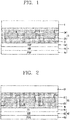
- FIG. 1 is a cross-sectional view of a related art general solar cell module.
- the related art solar cell module is formed by sequentially stacking a transparent tempered glass 1, an upper encapsulant 2a, a plurality of solar cells 3, a lower encapsulant 2b, and a back sheet 4.
- the plurality of solar cells 3 are fixedly packed between the upper encapsulant 2a and the lower encapsulant 2b.
- an ethylene vinyl acetate (EVA) is largely used in order to firmly fix the solar cell 3 therein.
- the back sheet 4 is attached to a lower surface of the lower encapsulant 2b to block an introduction of moisture or oxygen degrading an output amount to thus prevent lowering of the output amount when the solar cell module is in use for a long period of time, and prevent degradation due to ultraviolet rays as well.
- back sheets used in solar cell modules need be formed of a material having properties such as heat resistance or durability sufficiently enduring high temperatures and humidity and ultraviolet rays to prevent a degradation of an output amount of solar cell modules and need to be low in price.
- the back sheet used in the solar cell module is formed by stacking a polyethylene terephthalate (PET) film 4b, a base substrate, having heat resistance, or the like, and fluorine-based films 4a and 4c having weather resistance.
- PET polyethylene terephthalate
- the back sheet 4 includes the PET film 4b as a base substrate and the fluorine-based films 4a and 4c bonded to the PET film 4b through an adhesive, and since the PET film 4b has excellent heat resistance and durability, it is largely used as a base substrate of the back sheet 1.
- fluorine-based films 4a and 4c a polyvinylidenflouride (PVDF) film or a polyvinyl fluoride (PVF) film is largely used, and these fluorine-based films 4a and 4c have excellent durability.
- PVDF polyvinylidenflouride
- PVF polyvinyl fluoride
- Korean patent Registration No. 10-1349734 discloses a back sheet for a solar cell module including polyethylene, polyester, and fluorine-coated layers.
- an aspect of the detailed description is to provide solar cell module in which contraction of a back sheet caused as the solar cell module is used for a long period of time is prevented and adhesion between an encapsulant and the back sheet is enhanced, and which has a stable structure.
- the present invention is defined by the features of the independent claim. Preferred beneficial embodiments thereof are defined by the sub-features of the dependent claims.
- a solar cell module includes: a transparent member; an encapsulant allowing the transparent member to be bonded to an upper surface thereof; a plurality of solar cells fixed within the encapsulant; and a back sheet bonded to a lower surface of the encapsulant, wherein the back sheet includes a substrate; a polytetrafluoroethylene film layer formed on a lower surface of the substrate; and a surface layer formed on an upper surface of the substrate and formed of polyethylene, as defined in claim 1.
- the encapsulant may be formed as a polyolefin-based encapsulant.
- the encapsulant may include an ethylene vinyl acetate-based encapsulant provided to cover upper portions of the plurality of solar cells, a polyolefin-based encapsulant provided to cover lower portions of the plurality of solar cells, and the surface layer may be bonded to the polyolefin-based encapsulant.
- the substrate may be a polyethyleneterephthalate film layer.
- the solar cell module of the present invention since the polyethylene (PE) film is used to form the surface layer of the back sheet, even though the solar cell module is used for a long period of time, contraction of the back sheet is prevented, and thus, the solar cell module may be prevented from being deformed in an outer appearance thereof due to contraction of the back sheet.
- PE polyethylene
- the solar cell module since the solar cell module is prevented from being deformed in an outer appearance thereof, the solar cell module may have a stable structure.
- FIG. 2 is a schematic cross-sectional view illustrating a solar cell module according to an embodiment of the present invention.
- the solar cell module is completed through a process of sequentially stacking a transparent member 10, an upper encapsulant 21, solar cells 30, a lower encapsulant 23, and a back sheet 40, and subsequently modularizing the resultant structure in order of performing exhausting on the resultant structure in a vacuum laminator for four minutes, pressing the resultant structure for one minute, and maintaining the resultant structure for 10 minutes.
- the transparent member 10 is formed of transparent tempered glass, or the like, and protect an upper portion of the solar cell 30.
- the encapsulants 21 and 23 fixedly pack a plurality of solar cells 30, and the back sheet 40 is bonded to a lower portion of the solar cells 30 to protect the solar cells 30 such that the solar cells 30 may be used for a long period of time.
- the back sheet 40 used in the solar cell module includes a substrate 43, a PTFE layer 45 formed on a lower surface of the substrate 43, and a surface layer 41.
- the substrate 43 is formed of various materials having bearing power, heat resistance, barrier properties (moisture barrier properties), and heat dissipation properties, and serves as a support of the back sheet 40.
- the substrate 43 is formed as a polyethylene terephthalate (PET) film layer to have enhanced bearing power and heat resistance
- PET film layer may be formed of a sheet of film or may be formed by stacking two or more film layers and laminating the film layers.
- a material used to form the substrate 43 is not limited to the PET film layer and the substrate 43 may be formed of various synthetic resin materials.
- the substrate 43 may be formed of polytetrafluoroethylene (PTFE), polybutyleneterephthalate (PBT), polyethylenenaphthalate (PEN), or polybutylenenaphthalate (PBN), and here, the substrate 43 may be formed by selecting one or more of these materials.
- PTFE polytetrafluoroethylene
- PBT polybutyleneterephthalate
- PEN polyethylenenaphthalate
- PBN polybutylenenaphthalate
- a thickness of the PET film layer is not particularly limited. However, if the thickness of the PET film layer is less than 50 ⁇ m, barrier properties, heat resistance, mechanical strength, and dimensional stability are degraded, and when the thickness of the PET film layer exceeds 1000 ⁇ m, flexibility may be degraded and production cost may increase.
- the thickness of the PET film layer ranges from 50 ⁇ m to 1000 ⁇ m.
- the surface layer 41 is formed on an upper surface of the substrate 43 and is in contact with the encapsulant 20 forming the solar cell module.
- the encapsulant 20 includes an upper encapsulant 21 and a lower encapsulant 23, and the upper encapsulant 21 and the lower encapsulant 23 are formed as polyolefin-based encapsulants.
- the upper encapsulant 21 may be formed as an ethylenevinylacetate (EVA) encapsulant
- the lower encapsulant 23 may be formed as a polyolefin-based encapsulant.
- EVA ethylenevinylacetate
- the surface layer 41 of the back sheet 40 is bonded to the polyolefin-based encapsulant forming the lower encapsulant 23.
- the polyethylene (PE) film is used to form the surface layer 41, even though the solar battery is used for a long period of time, the back sheet 40 does not contract, and thus, the overall shape of the solar cell module is prevented from being deformed.
- the surface layer 41 contains white inorganic substance, and tensile strength and dimensional stability of the back sheet 40 are enhanced through the white inorganic substance, and light of the sun incident onto the back sheet 40 is reflected toward the solar cell 30 to increase an amount of light received by the solar cell 30.
- a thickness of the surface layer 41 ranges from 5 ⁇ m to 30 ⁇ m to enhance an effect such as weather resistance, or the like.
- a polytetrafluoroethylene (PTFE) film layer 45 is formed on a lower surface of the substrate 43 forming an outermost surface of the back sheet 40.
- PTFE polytetrafluoroethylene
- the PTFE film layer has properties such as heat resistance, chemical resistance, and non-viscosity, allowing the solar cell module to have a stable structure.
- a thickness of the polytetrafluoroethylene (PTFE) film ranges from 10 ⁇ m to 250 ⁇ m. If the thickness of the PTFE film layer is less than 10 ⁇ m the thickness is too thin to obtain an effect such as mechanical properties, or the like, and if the thickness of the PTFE film layer exceeds 250 ⁇ m, flexibility of the back sheet 40 may be degraded and cost increases, and thus, the thickness of the PTFE film layer ranges from 10 ⁇ m 250 ⁇ m.
- the surface layer 41 or the PTFE film layer 45 may be bonded to the substrate 43 through thermal bonding, coating, or an adhesive, and an adhesive used herein may include an acrylic resin, an urethane-based resin, an epoxy-based resin.
- the related art back sheet 4 and the back sheet 40 according to an embodiment of the present invention were heated at a temperature of 150°C for 30 minutes and contraction percentages of the related art back sheet 4 and the back sheet 40 according to an embodiment of the present invention in a horizontal direction and in a vertical direction were measured.
- the back sheet 4 used for the related art solar cell module was formed by bonding polyvinylfluoride (PVF) film layer to upper and lower surfaces of the base substrate 4b
- the back sheet 40 according to an embodiment of the present invention was formed by bonding the polyethylene (PE) film layer 41 to an upper surface of the substrate layer 43 and the polytetrafluoroethylene (PTFE) film layer 45 to a lower surface of the substrate layer 43, and contraction percentages of the back sheet 40 of the comparative example and the back sheet 40 according to an embodiment of the present invention in both a horizontal direction and a vertical direction were measured. It can be noted that the contraction percentages of the back sheet 40 according to an embodiment of the present invention in the horizontal direction and vertical direction were significantly lower.
- the back sheet 4 contracts to cause the solar cell module to be deformed in an outer shape, reduce adhesion between the encapsulant 2 and the back sheet 4, and drastically degrade structural stability of the solar cell module.
- the back sheet 40 is formed of polytetrafluoroethylene (PTFE), even though the solar cell module is used for a long period of time, contraction of the back sheet 40 is prevented and adhesion between the encapsulant 20 and the back sheet 40 is strengthened.
- PTFE polytetrafluoroethylene
- the adhesion between the encapsulant 20 and the back sheet 40 is strengthened, separation between the encapsulant 20 and the back sheet 40 is prevented, allowing the solar cell module to have a more stable structure.
Landscapes
- Photovoltaic Devices (AREA)
- Laminated Bodies (AREA)
Description
- The present disclosure relates to a solar cell module, and more particularly, to a solar cell moduie in which contraction of a back sheet caused as the solar cell module is used for a long period of time is prevented and adhesion between an encapsulant and the back sheet is enhanced, and which has a stable structure.
- Recently, solar batteries have been developed as a next-generation environmentally friendly energy source and rapidly become prevalent to be used in houses and for the purposes of industrial purposes.
- A solar battery is formed by modularizing a plurality of solar cells.
- Here, a plurality of solar cells are fixedly packed in an encapsulation layer, and a back sheet is bonded as a sealing member to a lower surface of the encapsulation layer, so as to be modularized.
-
FIG. 1 is a cross-sectional view of a related art general solar cell module. - As illustrated in
FIG. 1 , the related art solar cell module is formed by sequentially stacking a transparent tempered glass 1, anupper encapsulant 2a, a plurality ofsolar cells 3, alower encapsulant 2b, and aback sheet 4. - The plurality of
solar cells 3 are fixedly packed between theupper encapsulant 2a and thelower encapsulant 2b. Here, as a material of theencapsulants 2, an ethylene vinyl acetate (EVA) is largely used in order to firmly fix thesolar cell 3 therein. - The
back sheet 4 is attached to a lower surface of thelower encapsulant 2b to block an introduction of moisture or oxygen degrading an output amount to thus prevent lowering of the output amount when the solar cell module is in use for a long period of time, and prevent degradation due to ultraviolet rays as well. - Meanwhile, recently, due to an increase in cost of solar cell modules, low-priced back sheets are urgently required.
- For this reason, back sheets used in solar cell modules need be formed of a material having properties such as heat resistance or durability sufficiently enduring high temperatures and humidity and ultraviolet rays to prevent a degradation of an output amount of solar cell modules and need to be low in price.
- In general, the back sheet used in the solar cell module is formed by stacking a polyethylene terephthalate (PET)
film 4b, a base substrate, having heat resistance, or the like, and fluorine-basedfilms 4a and 4c having weather resistance. - That is, the
back sheet 4 includes thePET film 4b as a base substrate and the fluorine-basedfilms 4a and 4c bonded to thePET film 4b through an adhesive, and since thePET film 4b has excellent heat resistance and durability, it is largely used as a base substrate of the back sheet 1. - Also, as the fluorine-based
films 4a and 4c, a polyvinylidenflouride (PVDF) film or a polyvinyl fluoride (PVF) film is largely used, and these fluorine-basedfilms 4a and 4c have excellent durability. - Regarding the back sheet used in the solar cell module configured as described above, Korean patent Registration No.
10-1349734 - However, in the registered technique, when the solar cell module is in use for a long period of time, a back sheet contracts to deform an external shape of the solar cell module and adhesion strength between the encapsulant and the back sheet is reduced to separate the encapsulant and the back sheet, resulting in a significant degradation of structural stability of the solar cell module.
US 2014/041716 A1 (KANG HAN JUN [KR] ET AL) 13 February 2014 (2014-02-13) discloses a back sheet for a solar cell module and a solar cell module including the same, wherein the solar cell module comprises a polyester film layer and a fluorine coating layer which coats at least one surface of the polyester film layer. A surface layer of the back sheet is formed on an upper surface of the polyester film layer, and includes a polyethylene film layer attached to an ethylene vinyl acetate (EVA) sheet of the solar cell. -
US 2010/108128 A1 (CHU LIH-LONG [US] ET AL) 6 May 2010 (2010-05-06) discloses co-extruded, multilayered polyolefin-based back sheet for electronic device modules. - Therefore, an aspect of the detailed description is to provide solar cell module in which contraction of a back sheet caused as the solar cell module is used for a long period of time is prevented and adhesion between an encapsulant and the back sheet is enhanced, and which has a stable structure. The present invention is defined by the features of the independent claim. Preferred beneficial embodiments thereof are defined by the sub-features of the dependent claims.
- To achieve these and other advantages and in accordance with the purpose of this specification, as embodied and broadly described herein, a solar cell module includes: a transparent member; an encapsulant allowing the transparent member to be bonded to an upper surface thereof; a plurality of solar cells fixed within the encapsulant; and a back sheet bonded to a lower surface of the encapsulant, wherein the back sheet includes a substrate; a polytetrafluoroethylene film layer formed on a lower surface of the substrate; and a surface layer formed on an upper surface of the substrate and formed of polyethylene, as defined in claim 1.
- The encapsulant may be formed as a polyolefin-based encapsulant.
- The encapsulant may include an ethylene vinyl acetate-based encapsulant provided to cover upper portions of the plurality of solar cells, a polyolefin-based encapsulant provided to cover lower portions of the plurality of solar cells, and the surface layer may be bonded to the polyolefin-based encapsulant.
- The substrate may be a polyethyleneterephthalate film layer.
- As described above, according to the solar cell module of the present invention, since the polyethylene (PE) film is used to form the surface layer of the back sheet, even though the solar cell module is used for a long period of time, contraction of the back sheet is prevented, and thus, the solar cell module may be prevented from being deformed in an outer appearance thereof due to contraction of the back sheet.
- In addition, since contraction of the back sheet is prevented, adhesion between the encapsulant and the back sheet in which solar cells are fixed may be strengthened.
- In addition, since the solar cell module is prevented from being deformed in an outer appearance thereof, the solar cell module may have a stable structure.
- Further scope of applicability of the present application will become more apparent from the detailed description given hereinafter.
- The accompanying drawings, which are included to provide a further understanding of the invention and are incorporated in and constitute a part of this specification, illustrate exemplary embodiments and together with the description serve to explain the principles of the invention.
- In the drawings:
-
FIG. 1 is a schematic cross-sectional view illustrating a related art solar cell module. -
FIG. 2 is a schematic cross-sectional view illustrating a solar cell module according to an embodiment of the present invention. - Description will now be given in detail of the exemplary embodiments, with reference to the accompanying drawings. For the sake of brief description with reference to the drawings, the same or equivalent components will be provided with the same reference numbers, and description thereof will not be repeated.
- Hereinafter, a solar cell module according to an embodiment of the present invention will be described in detail with reference to the accompanying drawings.
-
FIG. 2 is a schematic cross-sectional view illustrating a solar cell module according to an embodiment of the present invention. - As illustrated in
FIG. 2 , in general, the solar cell module is completed through a process of sequentially stacking atransparent member 10, anupper encapsulant 21,solar cells 30, alower encapsulant 23, and aback sheet 40, and subsequently modularizing the resultant structure in order of performing exhausting on the resultant structure in a vacuum laminator for four minutes, pressing the resultant structure for one minute, and maintaining the resultant structure for 10 minutes. - The
transparent member 10 is formed of transparent tempered glass, or the like, and protect an upper portion of thesolar cell 30. - The
encapsulants solar cells 30, and theback sheet 40 is bonded to a lower portion of thesolar cells 30 to protect thesolar cells 30 such that thesolar cells 30 may be used for a long period of time. - Meanwhile, the
back sheet 40 used in the solar cell module includes asubstrate 43, aPTFE layer 45 formed on a lower surface of thesubstrate 43, and asurface layer 41. - The
substrate 43 is formed of various materials having bearing power, heat resistance, barrier properties (moisture barrier properties), and heat dissipation properties, and serves as a support of theback sheet 40. - In an embodiment of the present invention, the
substrate 43 is formed as a polyethylene terephthalate (PET) film layer to have enhanced bearing power and heat resistance, and here, the PET film layer may be formed of a sheet of film or may be formed by stacking two or more film layers and laminating the film layers. - Also, a material used to form the
substrate 43 is not limited to the PET film layer and thesubstrate 43 may be formed of various synthetic resin materials. - For example, the
substrate 43 may be formed of polytetrafluoroethylene (PTFE), polybutyleneterephthalate (PBT), polyethylenenaphthalate (PEN), or polybutylenenaphthalate (PBN), and here, thesubstrate 43 may be formed by selecting one or more of these materials. - Also, a thickness of the PET film layer is not particularly limited. However, if the thickness of the PET film layer is less than 50 µm, barrier properties, heat resistance, mechanical strength, and dimensional stability are degraded, and when the thickness of the PET film layer exceeds 1000 µm, flexibility may be degraded and production cost may increase.
- Thus, preferably, the thickness of the PET film layer ranges from 50 µm to 1000 µm.
- The
surface layer 41 is formed on an upper surface of thesubstrate 43 and is in contact with theencapsulant 20 forming the solar cell module. - Here, the
encapsulant 20 includes anupper encapsulant 21 and alower encapsulant 23, and theupper encapsulant 21 and thelower encapsulant 23 are formed as polyolefin-based encapsulants. - Also, the
upper encapsulant 21 may be formed as an ethylenevinylacetate (EVA) encapsulant, and thelower encapsulant 23 may be formed as a polyolefin-based encapsulant. - Thus, when the
back sheet 40 used in the solar cell module is bonded to theencapsulant 20, thesurface layer 41 of theback sheet 40 is bonded to the polyolefin-based encapsulant forming thelower encapsulant 23. - According to the present invention, since the polyethylene (PE) film is used to form the
surface layer 41, even though the solar battery is used for a long period of time, theback sheet 40 does not contract, and thus, the overall shape of the solar cell module is prevented from being deformed. - Also, since contraction of the
back sheet 40 is prevented, adhesion between theencapsulant 20 and theback sheet 40 is strengthened. - Meanwhile, the
surface layer 41 contains white inorganic substance, and tensile strength and dimensional stability of theback sheet 40 are enhanced through the white inorganic substance, and light of the sun incident onto theback sheet 40 is reflected toward thesolar cell 30 to increase an amount of light received by thesolar cell 30. - A thickness of the
surface layer 41 ranges from 5 µm to 30 µm to enhance an effect such as weather resistance, or the like. - Meanwhile, a polytetrafluoroethylene (PTFE)
film layer 45 is formed on a lower surface of thesubstrate 43 forming an outermost surface of theback sheet 40. - The PTFE film layer has properties such as heat resistance, chemical resistance, and non-viscosity, allowing the solar cell module to have a stable structure.
- A thickness of the polytetrafluoroethylene (PTFE) film ranges from 10 µm to 250 µm. If the thickness of the PTFE film layer is less than 10 µm the thickness is too thin to obtain an effect such as mechanical properties, or the like, and if the thickness of the PTFE film layer exceeds 250 µm, flexibility of the
back sheet 40 may be degraded and cost increases, and thus, the thickness of the PTFE film layer ranges from 10 µm 250 µm. - Meanwhile, the
surface layer 41 or thePTFE film layer 45 may be bonded to thesubstrate 43 through thermal bonding, coating, or an adhesive, and an adhesive used herein may include an acrylic resin, an urethane-based resin, an epoxy-based resin. - The related art back
sheet 4 and theback sheet 40 according to an embodiment of the present invention were heated at a temperature of 150°C for 30 minutes and contraction percentages of the related art backsheet 4 and theback sheet 40 according to an embodiment of the present invention in a horizontal direction and in a vertical direction were measured.[Table 1] Configuration of back sheet Contraction percentage in horizontal direction Contraction percentage in vertical direction Comparative Example PVF/PET/PVF 1.2% 1.0% Embodiment PE/PET/PTFE 0.5% 0.4% - As illustrated in Table 1, the
back sheet 4 used for the related art solar cell module was formed by bonding polyvinylfluoride (PVF) film layer to upper and lower surfaces of thebase substrate 4b, and theback sheet 40 according to an embodiment of the present invention was formed by bonding the polyethylene (PE)film layer 41 to an upper surface of thesubstrate layer 43 and the polytetrafluoroethylene (PTFE)film layer 45 to a lower surface of thesubstrate layer 43, and contraction percentages of theback sheet 40 of the comparative example and theback sheet 40 according to an embodiment of the present invention in both a horizontal direction and a vertical direction were measured. It can be noted that the contraction percentages of theback sheet 40 according to an embodiment of the present invention in the horizontal direction and vertical direction were significantly lower. - As can be seen from the foregoing experiment, in the case of the related art, when the solar cell module is used for a long period of time, the
back sheet 4 contracts to cause the solar cell module to be deformed in an outer shape, reduce adhesion between theencapsulant 2 and theback sheet 4, and drastically degrade structural stability of the solar cell module. In contrast, in the case of the present invention, since theback sheet 40 is formed of polytetrafluoroethylene (PTFE), even though the solar cell module is used for a long period of time, contraction of theback sheet 40 is prevented and adhesion between the encapsulant 20 and theback sheet 40 is strengthened. - In addition, since the adhesion between the encapsulant 20 and the
back sheet 40 is strengthened, separation between the encapsulant 20 and theback sheet 40 is prevented, allowing the solar cell module to have a more stable structure. - The foregoing embodiments and advantages are merely exemplary and are not to be considered as limiting the present disclosure. The present teachings can be readily applied to other types of apparatuses. This description is intended to be illustrative, and not to limit the scope of the claims. Many alternatives, modifications, and variations will be apparent to those skilled in the art. The features, structures, methods, and other characteristics of the exemplary embodiments described herein may be combined in various ways to obtain additional and/or alternative exemplary embodiments.
- As the present features may be embodied in several forms without departing from the characteristics thereof, it should also be understood that the above-described embodiments are not limited by any of the details of the foregoing description, unless otherwise specified, but rather should be considered broadly within its scope as defined in the appended claims.
Claims (4)
- A solar cell module producing energy using the sunlight, wherein the solar cell module comprises:a transparent member (10);an encapsulant (20) allowing the transparent member to be bonded to an upper surface thereof;a plurality of solar cells (30) fixed within the encapsulant (20); anda back sheet (40) bonded to a lower surface of the encapsulant (20),wherein the back sheet comprises:a substrate (43);a polytetrafluoroethylene film layer (45) formed on a lower surface of the substrate (43), and having a thickness ranging from 10µm to 250 µm; characterized by a surface layer (41) formed on an upper surface of the substrate (43), formed of polyethylene, having a thickness ranging from 5µm to 30µm, and containing a white inorganic substance to enhance tensile strength and dimensional stability of the back sheet (40) and to reflect light of the sun incident onto the back sheet (40) toward the solar cell (30) to increase an amount of light received by the solar cell (30), wherein the surface layer (41) is disposed between the encapsulant (20) and the substrate (43).
- The solar cell module of claim 1, wherein the encapsulant (20) is formed as a polyolefin-based encapsulant.
- The solar cell module of claim 1, wherein the encapsulant (20) includes an ethylene vinyl acetate-based encapsulant (21) provided to cover upper portions of the plurality of solar cells (30), and a polyolefin-based encapsulant (23) provided to cover lower portions of the plurality of solar cells (30), and the surface layer (41) is bonded to the polyolefin-based encapsulant.
- The solar cell module of claim 2 or 3, wherein the substrate (43) is a polyethyleneterephthalate film layer.
Applications Claiming Priority (1)
| Application Number | Priority Date | Filing Date | Title |
|---|---|---|---|
| KR1020140175173A KR101604283B1 (en) | 2014-12-08 | 2014-12-08 | Solar cell module |
Publications (2)
| Publication Number | Publication Date |
|---|---|
| EP3032591A1 EP3032591A1 (en) | 2016-06-15 |
| EP3032591B1 true EP3032591B1 (en) | 2019-10-23 |
Family
ID=54014697
Family Applications (1)
| Application Number | Title | Priority Date | Filing Date |
|---|---|---|---|
| EP15183256.5A Active EP3032591B1 (en) | 2014-12-08 | 2015-09-01 | Solar cell module |
Country Status (6)
| Country | Link |
|---|---|
| US (1) | US20160163900A1 (en) |
| EP (1) | EP3032591B1 (en) |
| JP (1) | JP2016111334A (en) |
| KR (1) | KR101604283B1 (en) |
| CN (1) | CN105679870A (en) |
| ES (1) | ES2763846T3 (en) |
Families Citing this family (1)
| Publication number | Priority date | Publication date | Assignee | Title |
|---|---|---|---|---|
| KR102842723B1 (en) * | 2023-11-30 | 2025-08-05 | 주식회사 피에이지플렉스 | Backsheet for solar panels with transparent properties |
Family Cites Families (17)
| Publication number | Priority date | Publication date | Assignee | Title |
|---|---|---|---|---|
| JP5582729B2 (en) * | 2008-06-19 | 2014-09-03 | ステラケミファ株式会社 | Modification method of fluororesin film |
| KR20110034665A (en) * | 2008-07-11 | 2011-04-05 | 미쓰비시 쥬시 가부시끼가이샤 | Solar Cell Back Sheet |
| KR101620308B1 (en) * | 2008-11-06 | 2016-05-12 | 다우 글로벌 테크놀로지스 엘엘씨 | Co-extruded, multilayered polyolefin-based backsheet for electronic device modules |
| CN101823355B (en) * | 2009-03-03 | 2013-09-25 | E.I.内穆尔杜邦公司 | Polymer laminated film and solar panel using laminated film |
| CN102362365A (en) * | 2009-03-30 | 2012-02-22 | 琳得科株式会社 | Back protection sheet for solar cell module, solar cell module having the protection sheet, and method for manufacturing the solar cell module |
| JPWO2011090023A1 (en) * | 2010-01-20 | 2013-05-23 | 東レ株式会社 | Back surface sealing sheet for solar cell module and solar cell module |
| JP2011159711A (en) * | 2010-01-29 | 2011-08-18 | Sanyo Electric Co Ltd | Solar cell module |
| JP2012084587A (en) * | 2010-10-07 | 2012-04-26 | Lintec Corp | Protective sheet for solar cell module and solar cell module |
| CN102468353A (en) * | 2010-11-11 | 2012-05-23 | 天津市天塑科技集团有限公司技术中心 | Back plate composite film of solar photovoltaic cell module and preparation method thereof |
| KR101349734B1 (en) * | 2011-04-26 | 2014-01-16 | 율촌화학 주식회사 | Back sheet for solar cell module and solar cell module comprising the same |
| TW201410804A (en) * | 2012-06-08 | 2014-03-16 | Daikin Ind Ltd | Coating composition, back panel of solar cell module, and solar cell module |
| JP2014075568A (en) * | 2012-09-14 | 2014-04-24 | Toppan Printing Co Ltd | Solar cell surface protective sheet and solar cell module |
| KR101707268B1 (en) * | 2012-12-24 | 2017-02-15 | 주식회사 엘지화학 | Back sheet for optoelectronic device, optoelectronic device comprising the same and method for manufacturing the same |
| WO2014104722A1 (en) * | 2012-12-24 | 2014-07-03 | 주식회사 엘지화학 | Encapsulation material film |
| CN103254803A (en) * | 2013-05-21 | 2013-08-21 | 上海海优威电子技术有限公司 | Micro-foaming polyolefin solar photovoltaic module film |
| CN103552314A (en) * | 2013-11-07 | 2014-02-05 | 英利集团有限公司 | Solar cell backboard and solar cell assembly with same |
| CN103646978B (en) * | 2013-12-09 | 2016-04-13 | 韩帅 | Solar module |
-
2014
- 2014-12-08 KR KR1020140175173A patent/KR101604283B1/en active Active
-
2015
- 2015-09-01 EP EP15183256.5A patent/EP3032591B1/en active Active
- 2015-09-01 ES ES15183256T patent/ES2763846T3/en active Active
- 2015-09-01 US US14/842,704 patent/US20160163900A1/en not_active Abandoned
- 2015-09-30 JP JP2015193322A patent/JP2016111334A/en active Pending
- 2015-11-09 CN CN201510756430.0A patent/CN105679870A/en active Pending
Non-Patent Citations (1)
| Title |
|---|
| None * |
Also Published As
| Publication number | Publication date |
|---|---|
| EP3032591A1 (en) | 2016-06-15 |
| JP2016111334A (en) | 2016-06-20 |
| US20160163900A1 (en) | 2016-06-09 |
| KR101604283B1 (en) | 2016-03-17 |
| ES2763846T3 (en) | 2020-06-01 |
| CN105679870A (en) | 2016-06-15 |
Similar Documents
| Publication | Publication Date | Title |
|---|---|---|
| EP2416380B1 (en) | Protective sheet for solar battery module, solar battery module and method for producing solar battery module | |
| US20090272436A1 (en) | Non-glass photovoltaic module and methods for manufacture | |
| US20130167928A1 (en) | Solar cell sealing sheet and flexible solar cell module | |
| US20110139225A1 (en) | Shaped photovoltaic module | |
| EP1921684A1 (en) | Solar cell module and process for manufacture thereof | |
| CN103201851A (en) | Back sheet for solar cells and process for production thereof, and solar cell module | |
| WO2013042081A1 (en) | A flexible photovoltaic panel | |
| US20140311560A1 (en) | Multilayer laminate for photovoltaic applications | |
| JP2017153195A (en) | Solar cell module with snow melting function | |
| JP2012204458A (en) | Method for manufacturing solar cell module | |
| JP2012094742A (en) | Solar battery module and method for producing the same | |
| JP2000307137A (en) | Solar cell cover film and solar cell module using the same | |
| JP2009170770A (en) | Solar cell backsheet and solar cell module | |
| KR101076787B1 (en) | Preparation Method of Backside Protective Sheet for Solar Cell Module | |
| EP3032591A1 (en) | Solar cell module | |
| JP2008130647A (en) | Back sheet for solar cell module and solar cell module using the back sheet | |
| EP2824718B1 (en) | Photovoltaic module and fabricating method thereof | |
| JP2009170771A (en) | Solar cell backsheet and solar cell module | |
| KR101423402B1 (en) | Back sheet for solar cell module and solar cell module comprising the same | |
| JP2012195491A (en) | Sheet for flexible solar cells | |
| JP2014207251A (en) | Solar cell module | |
| JPH11254526A (en) | Laminating apparatus and laminating method | |
| JP2013165092A (en) | Manufacturing method of solar cell module | |
| JPWO2013031752A1 (en) | Method for manufacturing solar cell module, solar cell back surface sealing sheet, and solar cell module | |
| WO2023238844A1 (en) | Resin film for current collector sheets, film for current collector sheets, current collector sheet, solar cell element with current collector sheet, and solar cell |
Legal Events
| Date | Code | Title | Description |
|---|---|---|---|
| PUAI | Public reference made under article 153(3) epc to a published international application that has entered the european phase |
Free format text: ORIGINAL CODE: 0009012 |
|
| AK | Designated contracting states |
Kind code of ref document: A1 Designated state(s): AL AT BE BG CH CY CZ DE DK EE ES FI FR GB GR HR HU IE IS IT LI LT LU LV MC MK MT NL NO PL PT RO RS SE SI SK SM TR |
|
| AX | Request for extension of the european patent |
Extension state: BA ME |
|
| 17P | Request for examination filed |
Effective date: 20160823 |
|
| RBV | Designated contracting states (corrected) |
Designated state(s): AL AT BE BG CH CY CZ DE DK EE ES FI FR GB GR HR HU IE IS IT LI LT LU LV MC MK MT NL NO PL PT RO RS SE SI SK SM TR |
|
| STAA | Information on the status of an ep patent application or granted ep patent |
Free format text: STATUS: EXAMINATION IS IN PROGRESS |
|
| 17Q | First examination report despatched |
Effective date: 20170221 |
|
| GRAP | Despatch of communication of intention to grant a patent |
Free format text: ORIGINAL CODE: EPIDOSNIGR1 |
|
| STAA | Information on the status of an ep patent application or granted ep patent |
Free format text: STATUS: GRANT OF PATENT IS INTENDED |
|
| INTG | Intention to grant announced |
Effective date: 20190520 |
|
| RIN1 | Information on inventor provided before grant (corrected) |
Inventor name: KIM, DONG CHAN Inventor name: WON, CHANG SUB |
|
| GRAS | Grant fee paid |
Free format text: ORIGINAL CODE: EPIDOSNIGR3 |
|
| GRAA | (expected) grant |
Free format text: ORIGINAL CODE: 0009210 |
|
| STAA | Information on the status of an ep patent application or granted ep patent |
Free format text: STATUS: THE PATENT HAS BEEN GRANTED |
|
| AK | Designated contracting states |
Kind code of ref document: B1 Designated state(s): AL AT BE BG CH CY CZ DE DK EE ES FI FR GB GR HR HU IE IS IT LI LT LU LV MC MK MT NL NO PL PT RO RS SE SI SK SM TR |
|
| REG | Reference to a national code |
Ref country code: GB Ref legal event code: FG4D |
|
| REG | Reference to a national code |
Ref country code: CH Ref legal event code: EP |
|
| REG | Reference to a national code |
Ref country code: IE Ref legal event code: FG4D |
|
| REG | Reference to a national code |
Ref country code: DE Ref legal event code: R096 Ref document number: 602015040173 Country of ref document: DE |
|
| REG | Reference to a national code |
Ref country code: AT Ref legal event code: REF Ref document number: 1194671 Country of ref document: AT Kind code of ref document: T Effective date: 20191115 |
|
| REG | Reference to a national code |
Ref country code: NL Ref legal event code: MP Effective date: 20191023 |
|
| REG | Reference to a national code |
Ref country code: LT Ref legal event code: MG4D |
|
| PG25 | Lapsed in a contracting state [announced via postgrant information from national office to epo] |
Ref country code: SE Free format text: LAPSE BECAUSE OF FAILURE TO SUBMIT A TRANSLATION OF THE DESCRIPTION OR TO PAY THE FEE WITHIN THE PRESCRIBED TIME-LIMIT Effective date: 20191023 Ref country code: LV Free format text: LAPSE BECAUSE OF FAILURE TO SUBMIT A TRANSLATION OF THE DESCRIPTION OR TO PAY THE FEE WITHIN THE PRESCRIBED TIME-LIMIT Effective date: 20191023 Ref country code: LT Free format text: LAPSE BECAUSE OF FAILURE TO SUBMIT A TRANSLATION OF THE DESCRIPTION OR TO PAY THE FEE WITHIN THE PRESCRIBED TIME-LIMIT Effective date: 20191023 Ref country code: NL Free format text: LAPSE BECAUSE OF FAILURE TO SUBMIT A TRANSLATION OF THE DESCRIPTION OR TO PAY THE FEE WITHIN THE PRESCRIBED TIME-LIMIT Effective date: 20191023 Ref country code: NO Free format text: LAPSE BECAUSE OF FAILURE TO SUBMIT A TRANSLATION OF THE DESCRIPTION OR TO PAY THE FEE WITHIN THE PRESCRIBED TIME-LIMIT Effective date: 20200123 Ref country code: PL Free format text: LAPSE BECAUSE OF FAILURE TO SUBMIT A TRANSLATION OF THE DESCRIPTION OR TO PAY THE FEE WITHIN THE PRESCRIBED TIME-LIMIT Effective date: 20191023 Ref country code: GR Free format text: LAPSE BECAUSE OF FAILURE TO SUBMIT A TRANSLATION OF THE DESCRIPTION OR TO PAY THE FEE WITHIN THE PRESCRIBED TIME-LIMIT Effective date: 20200124 Ref country code: PT Free format text: LAPSE BECAUSE OF FAILURE TO SUBMIT A TRANSLATION OF THE DESCRIPTION OR TO PAY THE FEE WITHIN THE PRESCRIBED TIME-LIMIT Effective date: 20200224 Ref country code: FI Free format text: LAPSE BECAUSE OF FAILURE TO SUBMIT A TRANSLATION OF THE DESCRIPTION OR TO PAY THE FEE WITHIN THE PRESCRIBED TIME-LIMIT Effective date: 20191023 Ref country code: BG Free format text: LAPSE BECAUSE OF FAILURE TO SUBMIT A TRANSLATION OF THE DESCRIPTION OR TO PAY THE FEE WITHIN THE PRESCRIBED TIME-LIMIT Effective date: 20200123 |
|
| PG25 | Lapsed in a contracting state [announced via postgrant information from national office to epo] |
Ref country code: HR Free format text: LAPSE BECAUSE OF FAILURE TO SUBMIT A TRANSLATION OF THE DESCRIPTION OR TO PAY THE FEE WITHIN THE PRESCRIBED TIME-LIMIT Effective date: 20191023 Ref country code: IS Free format text: LAPSE BECAUSE OF FAILURE TO SUBMIT A TRANSLATION OF THE DESCRIPTION OR TO PAY THE FEE WITHIN THE PRESCRIBED TIME-LIMIT Effective date: 20200224 Ref country code: RS Free format text: LAPSE BECAUSE OF FAILURE TO SUBMIT A TRANSLATION OF THE DESCRIPTION OR TO PAY THE FEE WITHIN THE PRESCRIBED TIME-LIMIT Effective date: 20191023 |
|
| REG | Reference to a national code |
Ref country code: ES Ref legal event code: FG2A Ref document number: 2763846 Country of ref document: ES Kind code of ref document: T3 Effective date: 20200601 |
|
| PG25 | Lapsed in a contracting state [announced via postgrant information from national office to epo] |
Ref country code: AL Free format text: LAPSE BECAUSE OF FAILURE TO SUBMIT A TRANSLATION OF THE DESCRIPTION OR TO PAY THE FEE WITHIN THE PRESCRIBED TIME-LIMIT Effective date: 20191023 |
|
| REG | Reference to a national code |
Ref country code: DE Ref legal event code: R097 Ref document number: 602015040173 Country of ref document: DE |
|
| PG2D | Information on lapse in contracting state deleted |
Ref country code: IS |
|
| PG25 | Lapsed in a contracting state [announced via postgrant information from national office to epo] |
Ref country code: CZ Free format text: LAPSE BECAUSE OF FAILURE TO SUBMIT A TRANSLATION OF THE DESCRIPTION OR TO PAY THE FEE WITHIN THE PRESCRIBED TIME-LIMIT Effective date: 20191023 Ref country code: RO Free format text: LAPSE BECAUSE OF FAILURE TO SUBMIT A TRANSLATION OF THE DESCRIPTION OR TO PAY THE FEE WITHIN THE PRESCRIBED TIME-LIMIT Effective date: 20191023 Ref country code: DK Free format text: LAPSE BECAUSE OF FAILURE TO SUBMIT A TRANSLATION OF THE DESCRIPTION OR TO PAY THE FEE WITHIN THE PRESCRIBED TIME-LIMIT Effective date: 20191023 Ref country code: EE Free format text: LAPSE BECAUSE OF FAILURE TO SUBMIT A TRANSLATION OF THE DESCRIPTION OR TO PAY THE FEE WITHIN THE PRESCRIBED TIME-LIMIT Effective date: 20191023 Ref country code: IS Free format text: LAPSE BECAUSE OF FAILURE TO SUBMIT A TRANSLATION OF THE DESCRIPTION OR TO PAY THE FEE WITHIN THE PRESCRIBED TIME-LIMIT Effective date: 20200223 |
|
| PGFP | Annual fee paid to national office [announced via postgrant information from national office to epo] |
Ref country code: FR Payment date: 20200609 Year of fee payment: 6 |
|
| REG | Reference to a national code |
Ref country code: AT Ref legal event code: MK05 Ref document number: 1194671 Country of ref document: AT Kind code of ref document: T Effective date: 20191023 |
|
| PLBE | No opposition filed within time limit |
Free format text: ORIGINAL CODE: 0009261 |
|
| STAA | Information on the status of an ep patent application or granted ep patent |
Free format text: STATUS: NO OPPOSITION FILED WITHIN TIME LIMIT |
|
| PG25 | Lapsed in a contracting state [announced via postgrant information from national office to epo] |
Ref country code: SK Free format text: LAPSE BECAUSE OF FAILURE TO SUBMIT A TRANSLATION OF THE DESCRIPTION OR TO PAY THE FEE WITHIN THE PRESCRIBED TIME-LIMIT Effective date: 20191023 Ref country code: SM Free format text: LAPSE BECAUSE OF FAILURE TO SUBMIT A TRANSLATION OF THE DESCRIPTION OR TO PAY THE FEE WITHIN THE PRESCRIBED TIME-LIMIT Effective date: 20191023 |
|
| 26N | No opposition filed |
Effective date: 20200724 |
|
| PGFP | Annual fee paid to national office [announced via postgrant information from national office to epo] |
Ref country code: DE Payment date: 20200605 Year of fee payment: 6 Ref country code: GB Payment date: 20200709 Year of fee payment: 6 |
|
| PG25 | Lapsed in a contracting state [announced via postgrant information from national office to epo] |
Ref country code: SI Free format text: LAPSE BECAUSE OF FAILURE TO SUBMIT A TRANSLATION OF THE DESCRIPTION OR TO PAY THE FEE WITHIN THE PRESCRIBED TIME-LIMIT Effective date: 20191023 Ref country code: AT Free format text: LAPSE BECAUSE OF FAILURE TO SUBMIT A TRANSLATION OF THE DESCRIPTION OR TO PAY THE FEE WITHIN THE PRESCRIBED TIME-LIMIT Effective date: 20191023 |
|
| PGFP | Annual fee paid to national office [announced via postgrant information from national office to epo] |
Ref country code: IT Payment date: 20200910 Year of fee payment: 6 |
|
| PGFP | Annual fee paid to national office [announced via postgrant information from national office to epo] |
Ref country code: ES Payment date: 20201008 Year of fee payment: 6 |
|
| PG25 | Lapsed in a contracting state [announced via postgrant information from national office to epo] |
Ref country code: MC Free format text: LAPSE BECAUSE OF FAILURE TO SUBMIT A TRANSLATION OF THE DESCRIPTION OR TO PAY THE FEE WITHIN THE PRESCRIBED TIME-LIMIT Effective date: 20191023 |
|
| REG | Reference to a national code |
Ref country code: CH Ref legal event code: PL |
|
| REG | Reference to a national code |
Ref country code: BE Ref legal event code: MM Effective date: 20200930 |
|
| PG25 | Lapsed in a contracting state [announced via postgrant information from national office to epo] |
Ref country code: LU Free format text: LAPSE BECAUSE OF NON-PAYMENT OF DUE FEES Effective date: 20200901 |
|
| PG25 | Lapsed in a contracting state [announced via postgrant information from national office to epo] |
Ref country code: LI Free format text: LAPSE BECAUSE OF NON-PAYMENT OF DUE FEES Effective date: 20200930 Ref country code: IE Free format text: LAPSE BECAUSE OF NON-PAYMENT OF DUE FEES Effective date: 20200901 Ref country code: BE Free format text: LAPSE BECAUSE OF NON-PAYMENT OF DUE FEES Effective date: 20200930 Ref country code: CH Free format text: LAPSE BECAUSE OF NON-PAYMENT OF DUE FEES Effective date: 20200930 |
|
| REG | Reference to a national code |
Ref country code: DE Ref legal event code: R119 Ref document number: 602015040173 Country of ref document: DE |
|
| GBPC | Gb: european patent ceased through non-payment of renewal fee |
Effective date: 20210901 |
|
| PG25 | Lapsed in a contracting state [announced via postgrant information from national office to epo] |
Ref country code: TR Free format text: LAPSE BECAUSE OF FAILURE TO SUBMIT A TRANSLATION OF THE DESCRIPTION OR TO PAY THE FEE WITHIN THE PRESCRIBED TIME-LIMIT Effective date: 20191023 Ref country code: MT Free format text: LAPSE BECAUSE OF FAILURE TO SUBMIT A TRANSLATION OF THE DESCRIPTION OR TO PAY THE FEE WITHIN THE PRESCRIBED TIME-LIMIT Effective date: 20191023 Ref country code: CY Free format text: LAPSE BECAUSE OF FAILURE TO SUBMIT A TRANSLATION OF THE DESCRIPTION OR TO PAY THE FEE WITHIN THE PRESCRIBED TIME-LIMIT Effective date: 20191023 |
|
| PG25 | Lapsed in a contracting state [announced via postgrant information from national office to epo] |
Ref country code: MK Free format text: LAPSE BECAUSE OF FAILURE TO SUBMIT A TRANSLATION OF THE DESCRIPTION OR TO PAY THE FEE WITHIN THE PRESCRIBED TIME-LIMIT Effective date: 20191023 |
|
| PG25 | Lapsed in a contracting state [announced via postgrant information from national office to epo] |
Ref country code: GB Free format text: LAPSE BECAUSE OF NON-PAYMENT OF DUE FEES Effective date: 20210901 Ref country code: FR Free format text: LAPSE BECAUSE OF NON-PAYMENT OF DUE FEES Effective date: 20210930 Ref country code: DE Free format text: LAPSE BECAUSE OF NON-PAYMENT OF DUE FEES Effective date: 20220401 |
|
| REG | Reference to a national code |
Ref country code: ES Ref legal event code: FD2A Effective date: 20221026 |
|
| PG25 | Lapsed in a contracting state [announced via postgrant information from national office to epo] |
Ref country code: IT Free format text: LAPSE BECAUSE OF NON-PAYMENT OF DUE FEES Effective date: 20210901 |
|
| PG25 | Lapsed in a contracting state [announced via postgrant information from national office to epo] |
Ref country code: ES Free format text: LAPSE BECAUSE OF NON-PAYMENT OF DUE FEES Effective date: 20210902 |