EP3032507A2 - A security device with a full length lens - Google Patents
A security device with a full length lens Download PDFInfo
- Publication number
- EP3032507A2 EP3032507A2 EP15197620.6A EP15197620A EP3032507A2 EP 3032507 A2 EP3032507 A2 EP 3032507A2 EP 15197620 A EP15197620 A EP 15197620A EP 3032507 A2 EP3032507 A2 EP 3032507A2
- Authority
- EP
- European Patent Office
- Prior art keywords
- fresnel lens
- lens
- front cover
- edges
- fresnel
- Prior art date
- Legal status (The legal status is an assumption and is not a legal conclusion. Google has not performed a legal analysis and makes no representation as to the accuracy of the status listed.)
- Granted
Links
Images





Classifications
-
- G—PHYSICS
- G01—MEASURING; TESTING
- G01J—MEASUREMENT OF INTENSITY, VELOCITY, SPECTRAL CONTENT, POLARISATION, PHASE OR PULSE CHARACTERISTICS OF INFRARED, VISIBLE OR ULTRAVIOLET LIGHT; COLORIMETRY; RADIATION PYROMETRY
- G01J5/00—Radiation pyrometry, e.g. infrared or optical thermometry
- G01J5/0022—Radiation pyrometry, e.g. infrared or optical thermometry for sensing the radiation of moving bodies
- G01J5/0025—Living bodies
-
- G—PHYSICS
- G01—MEASURING; TESTING
- G01J—MEASUREMENT OF INTENSITY, VELOCITY, SPECTRAL CONTENT, POLARISATION, PHASE OR PULSE CHARACTERISTICS OF INFRARED, VISIBLE OR ULTRAVIOLET LIGHT; COLORIMETRY; RADIATION PYROMETRY
- G01J5/00—Radiation pyrometry, e.g. infrared or optical thermometry
- G01J5/02—Constructional details
- G01J5/0205—Mechanical elements; Supports for optical elements
-
- G—PHYSICS
- G01—MEASURING; TESTING
- G01J—MEASUREMENT OF INTENSITY, VELOCITY, SPECTRAL CONTENT, POLARISATION, PHASE OR PULSE CHARACTERISTICS OF INFRARED, VISIBLE OR ULTRAVIOLET LIGHT; COLORIMETRY; RADIATION PYROMETRY
- G01J5/00—Radiation pyrometry, e.g. infrared or optical thermometry
- G01J5/02—Constructional details
- G01J5/05—Means for preventing contamination of the components of the optical system; Means for preventing obstruction of the radiation path
-
- G—PHYSICS
- G01—MEASURING; TESTING
- G01J—MEASUREMENT OF INTENSITY, VELOCITY, SPECTRAL CONTENT, POLARISATION, PHASE OR PULSE CHARACTERISTICS OF INFRARED, VISIBLE OR ULTRAVIOLET LIGHT; COLORIMETRY; RADIATION PYROMETRY
- G01J5/00—Radiation pyrometry, e.g. infrared or optical thermometry
- G01J5/02—Constructional details
- G01J5/08—Optical arrangements
- G01J5/0806—Focusing or collimating elements, e.g. lenses or concave mirrors
-
- G—PHYSICS
- G01—MEASURING; TESTING
- G01J—MEASUREMENT OF INTENSITY, VELOCITY, SPECTRAL CONTENT, POLARISATION, PHASE OR PULSE CHARACTERISTICS OF INFRARED, VISIBLE OR ULTRAVIOLET LIGHT; COLORIMETRY; RADIATION PYROMETRY
- G01J5/00—Radiation pyrometry, e.g. infrared or optical thermometry
- G01J5/02—Constructional details
- G01J5/08—Optical arrangements
- G01J5/0831—Masks; Aperture plates; Spatial light modulators
-
- G—PHYSICS
- G01—MEASURING; TESTING
- G01J—MEASUREMENT OF INTENSITY, VELOCITY, SPECTRAL CONTENT, POLARISATION, PHASE OR PULSE CHARACTERISTICS OF INFRARED, VISIBLE OR ULTRAVIOLET LIGHT; COLORIMETRY; RADIATION PYROMETRY
- G01J5/00—Radiation pyrometry, e.g. infrared or optical thermometry
- G01J5/10—Radiation pyrometry, e.g. infrared or optical thermometry using electric radiation detectors
- G01J5/34—Radiation pyrometry, e.g. infrared or optical thermometry using electric radiation detectors using capacitors, e.g. pyroelectric capacitors
-
- G—PHYSICS
- G02—OPTICS
- G02B—OPTICAL ELEMENTS, SYSTEMS OR APPARATUS
- G02B1/00—Optical elements characterised by the material of which they are made; Optical coatings for optical elements
- G02B1/04—Optical elements characterised by the material of which they are made; Optical coatings for optical elements made of organic materials, e.g. plastics
- G02B1/041—Lenses
-
- G—PHYSICS
- G02—OPTICS
- G02B—OPTICAL ELEMENTS, SYSTEMS OR APPARATUS
- G02B3/00—Simple or compound lenses
- G02B3/02—Simple or compound lenses with non-spherical faces
- G02B3/08—Simple or compound lenses with non-spherical faces with discontinuous faces, e.g. Fresnel lens
-
- G—PHYSICS
- G02—OPTICS
- G02B—OPTICAL ELEMENTS, SYSTEMS OR APPARATUS
- G02B7/00—Mountings, adjusting means, or light-tight connections, for optical elements
- G02B7/02—Mountings, adjusting means, or light-tight connections, for optical elements for lenses
- G02B7/022—Mountings, adjusting means, or light-tight connections, for optical elements for lenses lens and mount having complementary engagement means, e.g. screw/thread
-
- G—PHYSICS
- G08—SIGNALLING
- G08B—SIGNALLING SYSTEMS, e.g. PERSONAL CALLING SYSTEMS; ORDER TELEGRAPHS; ALARM SYSTEMS
- G08B13/00—Burglar, theft or intruder alarms
- G08B13/18—Actuation by interference with heat, light, or radiation of shorter wavelength; Actuation by intruding sources of heat, light, or radiation of shorter wavelength
- G08B13/189—Actuation by interference with heat, light, or radiation of shorter wavelength; Actuation by intruding sources of heat, light, or radiation of shorter wavelength using passive radiation detection systems
- G08B13/19—Actuation by interference with heat, light, or radiation of shorter wavelength; Actuation by intruding sources of heat, light, or radiation of shorter wavelength using passive radiation detection systems using infrared-radiation detection systems
- G08B13/193—Actuation by interference with heat, light, or radiation of shorter wavelength; Actuation by intruding sources of heat, light, or radiation of shorter wavelength using passive radiation detection systems using infrared-radiation detection systems using focusing means
Definitions
- This application relates to a security device. More particularly, this application describes a security device having a Fresnel lens that covers the entire front face of the device.
- a passive infrared sensor is one type of security device that detects motion as it measures infrared (IR) energy radiating from objects in its field of view in conjunction with a pyroelectric detector and Fresnel lens array as the objects move in and out of the multiple detection zones created by the sensing elements in the pyroelectric detector and the multiple Fresnel elements in the array molded into the Fresnel lens.
- IR energy enters the security device through the front of the device, known as the "sensor face.”
- the sensor face of traditional security devices includes a front cover, which is an opaque cylindrical plastic shield comprising the greater portion of the face of the device, where the shield has a small window or opening.
- the window overlays a cylindrical Fresnel lens, which is an IR transparent polymer material.
- the Fresnel lens is comprised of an array of Fresnel lens elements and a border surrounding the array. Normally, the Fresnel lens is molded flat during manufacturing, then bent to fit the cylindrical conformation of the security device when installed.
- the Fresnel lens is traditionally trapped in place between the edges of the window in the front cover on the front surface and a bug-guard or lens retainer on the interior side.
- the present device has a unique lens structure and a more robust lens system retention means that reduces the residual stresses on the lens.
- a typical prior art PIR 10 includes a housing made of a front cover 12 and a back cover 20 joined together at their respective edges, a Fresnel lens 14, a bug guard 16, a printed circuit board assembly 18 containing a pyroelectric detector 22 and a microcontroller.
- the front cover 12, rear cover 20, and bug guard 16 are each unitary parts made of a thermoplastic material which is opaque in the visible and infrared spectra.
- the Fresnel lens 14 is made of a polymer material that is sufficiently transparent to infrared energy, typically high density polyethylene.
- the Fresnel lens 14 resides in a window or opening 24 in the front cover 12. This opening permits IR energy to reach the Fresnel lens14 and be focused onto a pyroelectric detector 22 located behind the Fresnel lens.
- the edges 34 of a typical prior art lens 14 are securely contained and not visible once installed in the device as the lens is trapped between the front cover 12 and bug guard 14 and is in contact with each along the lens border 32 which surrounds the array 30 of individual Fresnel elements 28.
- the front cover overlap of the lens is illustrated as 26.
- the lens contact area of the front cover 12 and bug guard 16 are cylindrically shaped forcing the lens to take on the same cylindrical shape once installed.
- the prior art lens is molded flat to insure proper formation of of the many Fresnel facets in individual Fresnel lens element 28.
- This lens like the prior art lenses is molded flat to insure the optical integrity of each Fresnel lens element in the array 56, then takes on the cylindrical shape of the front cover when installed. If the left and right edges 54 of the lens 42 are held securely in place over the entire length of the edge, the cylindrical contour will insure that the top and bottom edges 52 of the lens 42 are held in place with no gaps. To this end of controlling the left and right edges 54, multiple pin receiving tabs 58 and hooks 62 were added along these edges. Each of the hooks 62 and tabs 58 are inserted into individual slots in the front cover 44. Performing this task proved to be extremely difficult and not practical from a manufacturing standpoint. A bug guard is then snapped into the front cover/lens assembly.
- the bug guard contains pins that engage the holes in the lens tabs 58 positively controlling the tabs. This too was found to be difficult as the lens tabs 58 want to move outboard due to residual stresses in the bent lens making alignment of the holes with the bug guard pins cumbersome.
- the bug guard was installed, it was found that the residual stresses in the lens 52 which result from bending the lens into the cylinder shape cause the hooks to disengage and the portion of the left and right lens edges 54 that are between the tabs 64 pull away from the front cover producing unsightly gaps. This approach to securing the lens which is the obvious approach to those versed in the state of the art proved inadequate.
- the present security device solves the longevity problems of prior art devices.
- the unique lens structure and more robust lens system retention means described herein prolongs the life of the device by minimizing gaps in the device at the junction between the lens and the front cover. Manufacturing is also thereby simplified.
- the device 70 includes a Fresnel lens 72, a printed circuit board assembly 76 and a housing made of a front cover 74 and a back cover 78 joined together at their respective edges.
- the front cover 74 is a unitary part which includes of an array of Fresnel lens elements 86.
- the front cover 74 and back cover 78 are each unitary parts complementary in size to the Fresnel lens 72.
- the front and back covers 74 and 78 are made of a thermoplastic material.
- the Fresnel lens is made of high density polyethylene.
- the device 70 also includes a pyroelectric detector 82 within the housing and a microcontroller 106 in contact with the pyroelectric detector 82.
- the center portion 88 of the Fresnel lens 72 contains an array 86 of individual Fresnel lens elements. This center portion 88 of the Fresnel lens is molded flat to insure the optical integrity of each facet in each Fresnel lens element in the array 86.
- the left and right portions 92 of the Fresnel lens 72 extend from the left and right sides of the Fresnel lens array 86 to the left and right sides 84 of the Fresnel lens 72.
- the left and right portions 92 of Fresnel lens 72 contain walls 94 containing hook receiving holes 96, ribs 98 further connecting the walls to the outer surface of the lens, and the outer surface of the lens.
- the outer surface of the Fresnel lens in the left and right portion of the lens 92 are molded to a cylindrical shape whose radius is identical to the radius of the entire Fresnel lens 72 when installed in the front cover 74.
- the walls 94 are molded as such an angle that when the Fresnel lens 72 is bent to the final installed cylindrical shape that the two walls will be paralled and aligned with the direction of lens insertion into the front cover 74 thereby significantly simplifying the installation step.
- the Fresnel lens 72 of the device 70 is bent into a curved conformation. This bending causes some tension along the edges 84 of the Fresnel lens, which are attached to the edges 108 of front cover 74. This tension is reduced by the as molded cylindrical shape of the outer edges 92 of the Fresnel lens and the means by which the Fresnel lens 72 and the front cover 74 are connected.
- the Fresnel lens 72 has a protruding wall 94 along its left and right edges 84, which contains hook receiving holes 96. When installed on the front cover 74, the holes 96 receive the complementary hooks or flanges 104 contained within lens wall receiving edge length slots 102 located in the front cover 74along its edges 108.
- the wall 94 in the Fresnel lens 72 is located on an inner surface of the Fresnel lens 72.
- the hooks or flanges 104 of the Front cover 74 are similarly on its inner surface.
- ribs 98 that connect the wall 94 to the inner surface of the Fresnel lens 72. These ribs 98 help insure the hook receiving holes 96 in the Fresnel lens 72 remain securely located on the hooks 104 in the front cover 74 and insure that the cylindrically molded edges 92 in the Fresnel lens remain in the as molded shape. Further, the walls 94, ribs 98 and cylindrically molded left and right portions 92 of the Fresnel lens form a very rigid structural configuration insuring that residual stresses present at the left and right sides of center portion 88 once bent will not influence the shape of left and right regions 92.
- left and right edges 84 or the Fresnel lens 72 will remain cylindrical and in contact with front cover 74 with no gaps solving the deficiencies of the prior art.
Landscapes
- Physics & Mathematics (AREA)
- General Physics & Mathematics (AREA)
- Spectroscopy & Molecular Physics (AREA)
- Optics & Photonics (AREA)
- Engineering & Computer Science (AREA)
- Power Engineering (AREA)
- Photometry And Measurement Of Optical Pulse Characteristics (AREA)
- Burglar Alarm Systems (AREA)
Abstract
Description
- This application relates to a security device. More particularly, this application describes a security device having a Fresnel lens that covers the entire front face of the device.
- Security devices can detect events such as temperature fluctuation, movement, impact, and shock. A passive infrared sensor (PIR) is one type of security device that detects motion as it measures infrared (IR) energy radiating from objects in its field of view in conjunction with a pyroelectric detector and Fresnel lens array as the objects move in and out of the multiple detection zones created by the sensing elements in the pyroelectric detector and the multiple Fresnel elements in the array molded into the Fresnel lens. IR energy enters the security device through the front of the device, known as the "sensor face." The sensor face of traditional security devices includes a front cover, which is an opaque cylindrical plastic shield comprising the greater portion of the face of the device, where the shield has a small window or opening. The window overlays a cylindrical Fresnel lens, which is an IR transparent polymer material. The Fresnel lens is comprised of an array of Fresnel lens elements and a border surrounding the array. Normally, the Fresnel lens is molded flat during manufacturing, then bent to fit the cylindrical conformation of the security device when installed. The Fresnel lens is traditionally trapped in place between the edges of the window in the front cover on the front surface and a bug-guard or lens retainer on the interior side. Although this bending of the Fresnel lens creates considerable residual stresses in the lens, which, if not securely trapped between the front cover and the bug-guard, would lead to the edges lifting up from the sides and corners of the device as the lens tries to return to its original molded flat shape. In a PIR where the lens is to comprise the entire front face of the device, the edges or border of the lens cannot be trapped behind the front cover as it must reside on top of the front cover. It was found that lens retention via the use of hooks and pinned flanges would result in the lifting of the edges causes gaps or holes in the device wherein dust, bugs, and water can seep in, potentially damaging the device or shortening its lifetime. In addition, the lifting of the edges of the lens can lead to distortions in the detection of IR energy, causing the device to not work properly. Thus, there is a need for a security device that avoids these problems in the prior art. The present device has a unique lens structure and a more robust lens system retention means that reduces the residual stresses on the lens.
- Examples of security devices having a full face lens will now be described and contrasted with conventional devices, with reference to the accompanying drawings, in which:
-
FIG. 1 is a view of a security device typical of the prior art illustrating a front cover, a Fresnel lens and are back cover. -
FIG. 2 is an exploded view of the prior art security device ofFigure 1 . -
FIG. 3 is a front view of the prior art security device offigure 1 illustrating the border region of the Fresnel lens which is trapped by the front cover. -
FIG. 4 is an perspective view of the prior art security device offigure 1 with the front cover removed illustrating the Fresnel lens as installed on the bug guard. -
FIG. 5 contains plan and bottom views of the Fresnel lens in the prior art security device offigure 1 illustrating the flat molded form and the shape when installed in the device. -
FIG. 6 is a perspective view of the prior art Fresnel lens offigure 5 shown in the flat as-molded shape. -
FIG. 7 is a view of a security device illustrating a lens covering the full front face of the device, a front cover and a back cover. The device and lens are a prior version prototype. -
FIG. 8 is a view of the Fresnel lens in the prior version prototype device shown in the as installed cylindrical form. -
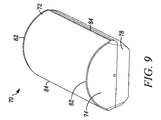
FIG. 9 is a view of a security device illustrating a lens covering the full front face of the device, a front cover and a back cover shown generally in accordance with an illustrated embodiment. -
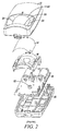
FIG. 10 is an exploded view of the security device offigure 9 shown generally in accordance with an illustrated embodiment. -
FIG. 11 contains a plan view and bottom view molded flat before attachment to the device and a bottom view as it would appear attached to the device shown generally in accordance with an illustrated embodiment. -
FIG. 12 is a perspective view of the Fresnel lens offigure 11 molded flat before attachment to the device shown generally in accordance with an illustrated embodiment. -
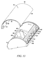
FIG. 13 is a view of a Fresnel lens as it would appear when being attached to the device shown generally in accordance with an illustrated embodiment. -
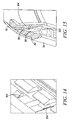
FIG 14 is an enlargement of a portion of the front cover fromfigure 13 illustrating the retention hooks shown generally in accordance with an illustrated embodiment. -
FIG. 15 is an enlarged view of a Fresnel lens locking mechanism, as it would appear when attached to the device shown generally in accordance with an illustrated embodiment. - A typical
prior art PIR 10 includes a housing made of afront cover 12 and aback cover 20 joined together at their respective edges, a Fresnellens 14, abug guard 16, a printedcircuit board assembly 18 containing apyroelectric detector 22 and a microcontroller. Thefront cover 12,rear cover 20, andbug guard 16 are each unitary parts made of a thermoplastic material which is opaque in the visible and infrared spectra. The Fresnellens 14 is made of a polymer material that is sufficiently transparent to infrared energy, typically high density polyethylene. The Fresnellens 14 resides in a window or opening 24 in thefront cover 12. This opening permits IR energy to reach the Fresnel lens14 and be focused onto apyroelectric detector 22 located behind the Fresnel lens. - The
edges 34 of a typicalprior art lens 14 are securely contained and not visible once installed in the device as the lens is trapped between thefront cover 12 andbug guard 14 and is in contact with each along thelens border 32 which surrounds thearray 30 of individual Fresnelelements 28. The front cover overlap of the lens is illustrated as 26. The lens contact area of thefront cover 12 andbug guard 16 are cylindrically shaped forcing the lens to take on the same cylindrical shape once installed. The prior art lens is molded flat to insure proper formation of of the many Fresnel facets in individual Fresnellens element 28. - Today, there is not one security device in the marketplace having a Fresnel lens that covers the entire front face of the device. Challenges with cosmetic and functional issues have not been overcome prior to the invention disclosed herein. A prototype of a version of a security device having a Fresnel lens that covers the entire front face of the device had been created by colleagues of the inventor. This device,
PIR 40, includes alens 42, afront cover 44, arear cover 46 and a bug-guard (not shown). The edges of thelens front cover 44 with no apparent gaps. This lens, like the prior art lenses is molded flat to insure the optical integrity of each Fresnel lens element in thearray 56, then takes on the cylindrical shape of the front cover when installed. If the left andright edges 54 of thelens 42 are held securely in place over the entire length of the edge, the cylindrical contour will insure that the top andbottom edges 52 of thelens 42 are held in place with no gaps. To this end of controlling the left andright edges 54, multiplepin receiving tabs 58 andhooks 62 were added along these edges. Each of thehooks 62 andtabs 58 are inserted into individual slots in thefront cover 44. Performing this task proved to be extremely difficult and not practical from a manufacturing standpoint. A bug guard is then snapped into the front cover/lens assembly. The bug guard contains pins that engage the holes in thelens tabs 58 positively controlling the tabs. This too was found to be difficult as thelens tabs 58 want to move outboard due to residual stresses in the bent lens making alignment of the holes with the bug guard pins cumbersome. Once the bug guard was installed, it was found that the residual stresses in thelens 52 which result from bending the lens into the cylinder shape cause the hooks to disengage and the portion of the left andright lens edges 54 that are between thetabs 64 pull away from the front cover producing unsightly gaps. This approach to securing the lens which is the obvious approach to those versed in the state of the art proved inadequate. - The present security device solves the longevity problems of prior art devices. The unique lens structure and more robust lens system retention means described herein prolongs the life of the device by minimizing gaps in the device at the junction between the lens and the front cover. Manufacturing is also thereby simplified.
- The
device 70 includes aFresnel lens 72, a printedcircuit board assembly 76 and a housing made of afront cover 74 and aback cover 78 joined together at their respective edges. Thefront cover 74 is a unitary part which includes of an array ofFresnel lens elements 86. Thefront cover 74 andback cover 78 are each unitary parts complementary in size to theFresnel lens 72. The front and back covers 74 and 78 are made of a thermoplastic material. The Fresnel lens is made of high density polyethylene. Thedevice 70 also includes apyroelectric detector 82 within the housing and amicrocontroller 106 in contact with thepyroelectric detector 82. - The
center portion 88 of theFresnel lens 72 contains anarray 86 of individual Fresnel lens elements. Thiscenter portion 88 of the Fresnel lens is molded flat to insure the optical integrity of each facet in each Fresnel lens element in thearray 86. The left andright portions 92 of theFresnel lens 72 extend from the left and right sides of theFresnel lens array 86 to the left andright sides 84 of theFresnel lens 72. The left andright portions 92 ofFresnel lens 72 containwalls 94 containinghook receiving holes 96,ribs 98 further connecting the walls to the outer surface of the lens, and the outer surface of the lens. The outer surface of the Fresnel lens in the left and right portion of thelens 92 are molded to a cylindrical shape whose radius is identical to the radius of theentire Fresnel lens 72 when installed in thefront cover 74. When installed the left andright portions 92 of theFresnel lens 72 and thecenter portion 88 of the Fresnel lens will have the same radius R. Thewalls 94 are molded as such an angle that when theFresnel lens 72 is bent to the final installed cylindrical shape that the two walls will be paralled and aligned with the direction of lens insertion into thefront cover 74 thereby significantly simplifying the installation step. - The
Fresnel lens 72 of thedevice 70 is bent into a curved conformation. This bending causes some tension along theedges 84 of the Fresnel lens, which are attached to theedges 108 offront cover 74. This tension is reduced by the as molded cylindrical shape of theouter edges 92 of the Fresnel lens and the means by which theFresnel lens 72 and thefront cover 74 are connected. - The
Fresnel lens 72 has a protrudingwall 94 along its left andright edges 84, which contains hook receiving holes 96. When installed on thefront cover 74, theholes 96 receive the complementary hooks orflanges 104 contained within lens wall receivingedge length slots 102 located in the front cover 74along itsedges 108. Thewall 94 in theFresnel lens 72 is located on an inner surface of theFresnel lens 72. The hooks orflanges 104 of theFront cover 74 are similarly on its inner surface. - There are
ribs 98 that connect thewall 94 to the inner surface of theFresnel lens 72. Theseribs 98 help insure thehook receiving holes 96 in theFresnel lens 72 remain securely located on thehooks 104 in thefront cover 74 and insure that the cylindrically moldededges 92 in the Fresnel lens remain in the as molded shape. Further, thewalls 94,ribs 98 and cylindrically molded left andright portions 92 of the Fresnel lens form a very rigid structural configuration insuring that residual stresses present at the left and right sides ofcenter portion 88 once bent will not influence the shape of left andright regions 92. Therefore left andright edges 84 or theFresnel lens 72 will remain cylindrical and in contact withfront cover 74 with no gaps solving the deficiencies of the prior art. There areadditional ribs 98 at theshorter edges 82 of the Fresnel lens, whichshorter edges 82 are not involved in attaching theFresnel lens 72 to the front cover. The additional ribs on the shorter edges help prevent tampering with thedevice 70. - From the foregoing, it will be observed that numerous variations and modifications may be effected without departing from the spirit and scope hereof. It is to be understood that no limitation with respect to the specific apparatus illustrated herein is intended or should be inferred. It is, of course, intended to cover by the appended claims all such modifications as fall within the scope of the claims. Further, logic flows depicted in the figures do not require the particular order shown, or sequential order, to achieve desirable results. Other steps may be provided, or steps may be eliminated, from the described flows, and other components may be add to, or removed from the described embodiments.
Claims (15)
- An apparatus comprising:a housing including a Fresnel lens and a front cover joined together at their respective edges;wherein the Fresnel lens comprises a unitary part comprising an array of Fresnel lens elements;wherein the front cover comprises a unitary part complementary in size to the Fresnel lens;a pyroelectric detector contained within the housing; anda microcontroller in contact with the pyroelectric detector.
- The apparatus of claim 1 wherein the Fresnel lens comprises high density polyethylene.
- The apparatus of claim 1 wherein the front cover comprises a thermoplastic polymer material.
- The apparatus of claim 1 wherein the Fresnel lens comprises a curved surface.
- The apparatus of claim 1 wherein the Fresnel lens comprises a protruding wall along the edges that attaches to the front cover edges wherein the wall is located on an inner surface of the Fresnel lens.
- The apparatus of claim 5 wherein the protruding wall comprises hook receiving holes or slots and the front cover comprises complementary hooks or flanges that engage the holes.
- The apparatus of claim 5 wherein the protruding wall further comprises ribs forming a connection to the Fresnel lens.
- The apparatus of claim 1 wherein the Fresnel lens comprises ribs at the edges not having a protruding wall.
- The apparatus of claim 5 wherein the center portion of the Fresnel lens containing the array of Fresnel lens elements are is molded in a flat plane.
- The apparatus of claim 5 wherein the portion of the Fresnel lens left and right of the array of Fresnel elements are molded in the final shape of the installed lens.
- The apparatus of claim 10 wherein the final shape of the installed Fresnel lens is a cylinder of constant radius.
- The apparatus of claim 5 wherein the protruding wall comprises hooks or flanges and the front cover comprises complementary hook receiving holes or slots that engage the hooks.
- The apparatus of claim 5 wherein when the Fresnel lens is formed to the final installed shape, the protruding walls are parallel and aligned in the lens insertion direction simplifying the assembly process.
- An apparatus comprising:a housing including a rectangular front piece and a rectangular middle piece of matching dimensions joined along the edges of their longer sides to form an inner cavity within the housing and a rectangular back piece of matching dimensions;wherein the front piece comprises a curved surface that includes an array of Fresnel lens elements;wherein the middle and back pieces comprise- a thermoplastic material;a pyroelectric detector contained within the inner cavity; anda microcontroller within the inner cavity wherein the microcontroller is in contact with the pyroelectric detector.
- The apparatus of claim 14 wherein the front piece comprises high density polyethylene.
Applications Claiming Priority (1)
| Application Number | Priority Date | Filing Date | Title |
|---|---|---|---|
| US14/565,976 US9410847B2 (en) | 2014-12-10 | 2014-12-10 | Security device with a full length lens |
Publications (3)
| Publication Number | Publication Date |
|---|---|
| EP3032507A2 true EP3032507A2 (en) | 2016-06-15 |
| EP3032507A3 EP3032507A3 (en) | 2017-10-04 |
| EP3032507B1 EP3032507B1 (en) | 2021-08-25 |
Family
ID=54780169
Family Applications (1)
| Application Number | Title | Priority Date | Filing Date |
|---|---|---|---|
| EP15197620.6A Active EP3032507B1 (en) | 2014-12-10 | 2015-12-02 | A security device with a full length lens |
Country Status (5)
| Country | Link |
|---|---|
| US (1) | US9410847B2 (en) |
| EP (1) | EP3032507B1 (en) |
| CN (1) | CN105698939A (en) |
| CA (1) | CA2913637A1 (en) |
| ES (1) | ES2892926T3 (en) |
Cited By (1)
| Publication number | Priority date | Publication date | Assignee | Title |
|---|---|---|---|---|
| IT202300027270A1 (en) * | 2023-12-19 | 2025-06-19 | Tecno Switch S R L | FRONT COVER FOR MOTION DETECTION MODULES AND RELATED MOTION DETECTION MODULE |
Families Citing this family (9)
| Publication number | Priority date | Publication date | Assignee | Title |
|---|---|---|---|---|
| USD773100S1 (en) * | 2015-10-05 | 2016-11-29 | RAB Lighting Inc. | Wallpack LED light fixture |
| US9927301B2 (en) * | 2015-10-26 | 2018-03-27 | Bosch Security Systems, Inc. | Detector lens |
| USD800943S1 (en) * | 2016-04-20 | 2017-10-24 | Above All Lighting Inc. | Door light |
| USD823520S1 (en) * | 2016-12-19 | 2018-07-17 | RAB Lighting Inc. | Half bell light fixture |
| USD938641S1 (en) * | 2017-12-13 | 2021-12-14 | Qinghui Liang | Solar wall light |
| USD1021217S1 (en) | 2020-01-10 | 2024-04-02 | RAB Lighting Inc. | Luminaire with forward facing recess |
| USD942294S1 (en) * | 2020-03-16 | 2022-02-01 | Honeywell International Inc. | Enclosure for a security system controller |
| USD942295S1 (en) * | 2020-03-27 | 2022-02-01 | Honeywell International Inc. | Enclosure for a security system controller |
| US12367745B2 (en) * | 2022-12-05 | 2025-07-22 | Stmicroelectronics S.R.L. | Passive infrared sensor with patterned lens |
Family Cites Families (12)
| Publication number | Priority date | Publication date | Assignee | Title |
|---|---|---|---|---|
| AU580898B2 (en) * | 1986-02-25 | 1989-02-02 | Matsushita Electric Works Ltd. | Infrared detector |
| US5124546A (en) * | 1990-04-24 | 1992-06-23 | The Watt Stopper | Method and apparatus for refracting light to an optical detector |
| US5393978A (en) * | 1993-02-04 | 1995-02-28 | Schwarz; Frank | Infrared detectors having front and rear fields of view |
| US6653635B2 (en) * | 2001-04-25 | 2003-11-25 | Interquartz (Malaysia) Bhd. Representative Office | Detector with wide detecting range and method of extending the detecting range |
| US7321120B1 (en) * | 2004-11-26 | 2008-01-22 | Protectconnect, Inc. | Motion detector module |
| US7432690B2 (en) * | 2005-05-27 | 2008-10-07 | Hubbell Incorporated | Dual circuit wall switch occupancy sensor and method of operating same |
| EP2390855A4 (en) * | 2009-01-22 | 2012-10-17 | Optex Co Ltd | Intrusion detection device |
| US20110253516A1 (en) * | 2010-03-05 | 2011-10-20 | The Watt Stopper, Inc. | Modular Sensor Switch |
| US9123222B2 (en) * | 2012-03-15 | 2015-09-01 | Ninve Jr. Inc. | Apparatus and method for detecting tampering with an infra-red motion sensor |
| US9136839B2 (en) * | 2013-01-22 | 2015-09-15 | Wenzhou Mtlc Electric Appliances Co., Ltd. | Power switch |
| US8912902B1 (en) * | 2013-05-31 | 2014-12-16 | Honeywell International, Inc. | Lookdown enable/disable for detectors |
| US9927301B2 (en) * | 2015-10-26 | 2018-03-27 | Bosch Security Systems, Inc. | Detector lens |
-
2014
- 2014-12-10 US US14/565,976 patent/US9410847B2/en active Active
-
2015
- 2015-11-30 CA CA2913637A patent/CA2913637A1/en not_active Abandoned
- 2015-12-02 EP EP15197620.6A patent/EP3032507B1/en active Active
- 2015-12-02 ES ES15197620T patent/ES2892926T3/en active Active
- 2015-12-09 CN CN201510900151.7A patent/CN105698939A/en active Pending
Non-Patent Citations (1)
| Title |
|---|
| None |
Cited By (1)
| Publication number | Priority date | Publication date | Assignee | Title |
|---|---|---|---|---|
| IT202300027270A1 (en) * | 2023-12-19 | 2025-06-19 | Tecno Switch S R L | FRONT COVER FOR MOTION DETECTION MODULES AND RELATED MOTION DETECTION MODULE |
Also Published As
| Publication number | Publication date |
|---|---|
| EP3032507B1 (en) | 2021-08-25 |
| CA2913637A1 (en) | 2016-06-10 |
| CN105698939A (en) | 2016-06-22 |
| ES2892926T3 (en) | 2022-02-07 |
| EP3032507A3 (en) | 2017-10-04 |
| US9410847B2 (en) | 2016-08-09 |
| US20160169743A1 (en) | 2016-06-16 |
Similar Documents
| Publication | Publication Date | Title |
|---|---|---|
| US9410847B2 (en) | Security device with a full length lens | |
| US11747718B2 (en) | Camera module | |
| US9502812B2 (en) | Connector having movable housing within frame | |
| KR102556516B1 (en) | Camera module | |
| CN213920851U (en) | Rearview assembly | |
| AU2014386957B2 (en) | Metal ear tag with overmoulded cover for transponder housing, and method of assembling the same | |
| US7763807B2 (en) | Connector box for solar panel | |
| US20130059481A1 (en) | Plug-in connector and a plug-in module system | |
| CN105518524A (en) | Image acquisition module set and ligh-shielding cover | |
| KR100346711B1 (en) | Projection television | |
| US20170110816A1 (en) | Clip and electrical connector assembly | |
| KR20150004372U (en) | Infrared detection sensor | |
| CN204678262U (en) | A kind of light fixture cover and lens fixing structure and apply the light fixture of this fixed structure | |
| CN205724110U (en) | Photoelectric sensor | |
| KR101597786B1 (en) | Protection case for portable terminal manufacturing method thereof | |
| TWI506321B (en) | Optoelectronic module with shutter member | |
| CN220043524U (en) | Image pickup apparatus | |
| CN206601552U (en) | One kind is every aperture and video camera | |
| JP6077429B2 (en) | Hot air heater | |
| WO2001006765A8 (en) | E-film cartridge with sensor avoidance feature | |
| JP4622989B2 (en) | Electronic device frame structure | |
| ES3031292T3 (en) | A kit of parts including a sensor unit assembly and sensor unit assembled from it | |
| JP3861969B2 (en) | Light curtain creation device | |
| KR102116093B1 (en) | Housing assembly for security camera | |
| US10644451B2 (en) | Dynamic keying assembly |
Legal Events
| Date | Code | Title | Description |
|---|---|---|---|
| PUAI | Public reference made under article 153(3) epc to a published international application that has entered the european phase |
Free format text: ORIGINAL CODE: 0009012 |
|
| 17P | Request for examination filed |
Effective date: 20151202 |
|
| AK | Designated contracting states |
Kind code of ref document: A2 Designated state(s): AL AT BE BG CH CY CZ DE DK EE ES FI FR GB GR HR HU IE IS IT LI LT LU LV MC MK MT NL NO PL PT RO RS SE SI SK SM TR |
|
| AX | Request for extension of the european patent |
Extension state: BA ME |
|
| RIC1 | Information provided on ipc code assigned before grant |
Ipc: G01J 5/02 20060101ALI20170116BHEP Ipc: G01J 5/04 20060101ALI20170116BHEP Ipc: G01J 5/08 20060101ALI20170116BHEP Ipc: G08B 13/193 20060101AFI20170116BHEP |
|
| PUAL | Search report despatched |
Free format text: ORIGINAL CODE: 0009013 |
|
| AK | Designated contracting states |
Kind code of ref document: A3 Designated state(s): AL AT BE BG CH CY CZ DE DK EE ES FI FR GB GR HR HU IE IS IT LI LT LU LV MC MK MT NL NO PL PT RO RS SE SI SK SM TR |
|
| AX | Request for extension of the european patent |
Extension state: BA ME |
|
| RIC1 | Information provided on ipc code assigned before grant |
Ipc: G02B 1/04 20060101ALI20170831BHEP Ipc: G01J 5/08 20060101ALI20170831BHEP Ipc: G01J 5/34 20060101ALI20170831BHEP Ipc: G01J 5/04 20060101ALI20170831BHEP Ipc: G08B 13/193 20060101AFI20170831BHEP Ipc: G01J 5/00 20060101ALI20170831BHEP Ipc: G02B 3/08 20060101ALI20170831BHEP Ipc: G01J 5/02 20060101ALI20170831BHEP Ipc: G02B 7/02 20060101ALI20170831BHEP |
|
| STAA | Information on the status of an ep patent application or granted ep patent |
Free format text: STATUS: EXAMINATION IS IN PROGRESS |
|
| 17Q | First examination report despatched |
Effective date: 20200610 |
|
| GRAP | Despatch of communication of intention to grant a patent |
Free format text: ORIGINAL CODE: EPIDOSNIGR1 |
|
| STAA | Information on the status of an ep patent application or granted ep patent |
Free format text: STATUS: GRANT OF PATENT IS INTENDED |
|
| INTG | Intention to grant announced |
Effective date: 20210219 |
|
| RIN1 | Information on inventor provided before grant (corrected) |
Inventor name: BUCKLEY, MARK C. |
|
| RAP1 | Party data changed (applicant data changed or rights of an application transferred) |
Owner name: ADEMCO INC. |
|
| GRAJ | Information related to disapproval of communication of intention to grant by the applicant or resumption of examination proceedings by the epo deleted |
Free format text: ORIGINAL CODE: EPIDOSDIGR1 |
|
| STAA | Information on the status of an ep patent application or granted ep patent |
Free format text: STATUS: EXAMINATION IS IN PROGRESS |
|
| GRAP | Despatch of communication of intention to grant a patent |
Free format text: ORIGINAL CODE: EPIDOSNIGR1 |
|
| STAA | Information on the status of an ep patent application or granted ep patent |
Free format text: STATUS: GRANT OF PATENT IS INTENDED |
|
| INTC | Intention to grant announced (deleted) | ||
| GRAS | Grant fee paid |
Free format text: ORIGINAL CODE: EPIDOSNIGR3 |
|
| GRAA | (expected) grant |
Free format text: ORIGINAL CODE: 0009210 |
|
| STAA | Information on the status of an ep patent application or granted ep patent |
Free format text: STATUS: THE PATENT HAS BEEN GRANTED |
|
| INTG | Intention to grant announced |
Effective date: 20210629 |
|
| AK | Designated contracting states |
Kind code of ref document: B1 Designated state(s): AL AT BE BG CH CY CZ DE DK EE ES FI FR GB GR HR HU IE IS IT LI LT LU LV MC MK MT NL NO PL PT RO RS SE SI SK SM TR |
|
| REG | Reference to a national code |
Ref country code: CH Ref legal event code: EP |
|
| REG | Reference to a national code |
Ref country code: IE Ref legal event code: FG4D Ref country code: AT Ref legal event code: REF Ref document number: 1424577 Country of ref document: AT Kind code of ref document: T Effective date: 20210915 |
|
| REG | Reference to a national code |
Ref country code: DE Ref legal event code: R096 Ref document number: 602015072558 Country of ref document: DE |
|
| REG | Reference to a national code |
Ref country code: SE Ref legal event code: TRGR |
|
| REG | Reference to a national code |
Ref country code: LT Ref legal event code: MG9D |
|
| REG | Reference to a national code |
Ref country code: NL Ref legal event code: MP Effective date: 20210825 |
|
| REG | Reference to a national code |
Ref country code: AT Ref legal event code: MK05 Ref document number: 1424577 Country of ref document: AT Kind code of ref document: T Effective date: 20210825 |
|
| PG25 | Lapsed in a contracting state [announced via postgrant information from national office to epo] |
Ref country code: RS Free format text: LAPSE BECAUSE OF FAILURE TO SUBMIT A TRANSLATION OF THE DESCRIPTION OR TO PAY THE FEE WITHIN THE PRESCRIBED TIME-LIMIT Effective date: 20210825 Ref country code: HR Free format text: LAPSE BECAUSE OF FAILURE TO SUBMIT A TRANSLATION OF THE DESCRIPTION OR TO PAY THE FEE WITHIN THE PRESCRIBED TIME-LIMIT Effective date: 20210825 Ref country code: AT Free format text: LAPSE BECAUSE OF FAILURE TO SUBMIT A TRANSLATION OF THE DESCRIPTION OR TO PAY THE FEE WITHIN THE PRESCRIBED TIME-LIMIT Effective date: 20210825 Ref country code: BG Free format text: LAPSE BECAUSE OF FAILURE TO SUBMIT A TRANSLATION OF THE DESCRIPTION OR TO PAY THE FEE WITHIN THE PRESCRIBED TIME-LIMIT Effective date: 20211125 Ref country code: LT Free format text: LAPSE BECAUSE OF FAILURE TO SUBMIT A TRANSLATION OF THE DESCRIPTION OR TO PAY THE FEE WITHIN THE PRESCRIBED TIME-LIMIT Effective date: 20210825 Ref country code: FI Free format text: LAPSE BECAUSE OF FAILURE TO SUBMIT A TRANSLATION OF THE DESCRIPTION OR TO PAY THE FEE WITHIN THE PRESCRIBED TIME-LIMIT Effective date: 20210825 Ref country code: PT Free format text: LAPSE BECAUSE OF FAILURE TO SUBMIT A TRANSLATION OF THE DESCRIPTION OR TO PAY THE FEE WITHIN THE PRESCRIBED TIME-LIMIT Effective date: 20211227 Ref country code: NO Free format text: LAPSE BECAUSE OF FAILURE TO SUBMIT A TRANSLATION OF THE DESCRIPTION OR TO PAY THE FEE WITHIN THE PRESCRIBED TIME-LIMIT Effective date: 20211125 |
|
| REG | Reference to a national code |
Ref country code: ES Ref legal event code: FG2A Ref document number: 2892926 Country of ref document: ES Kind code of ref document: T3 Effective date: 20220207 |
|
| PG25 | Lapsed in a contracting state [announced via postgrant information from national office to epo] |
Ref country code: PL Free format text: LAPSE BECAUSE OF FAILURE TO SUBMIT A TRANSLATION OF THE DESCRIPTION OR TO PAY THE FEE WITHIN THE PRESCRIBED TIME-LIMIT Effective date: 20210825 Ref country code: LV Free format text: LAPSE BECAUSE OF FAILURE TO SUBMIT A TRANSLATION OF THE DESCRIPTION OR TO PAY THE FEE WITHIN THE PRESCRIBED TIME-LIMIT Effective date: 20210825 Ref country code: GR Free format text: LAPSE BECAUSE OF FAILURE TO SUBMIT A TRANSLATION OF THE DESCRIPTION OR TO PAY THE FEE WITHIN THE PRESCRIBED TIME-LIMIT Effective date: 20211126 |
|
| PG25 | Lapsed in a contracting state [announced via postgrant information from national office to epo] |
Ref country code: NL Free format text: LAPSE BECAUSE OF FAILURE TO SUBMIT A TRANSLATION OF THE DESCRIPTION OR TO PAY THE FEE WITHIN THE PRESCRIBED TIME-LIMIT Effective date: 20210825 |
|
| PG25 | Lapsed in a contracting state [announced via postgrant information from national office to epo] |
Ref country code: DK Free format text: LAPSE BECAUSE OF FAILURE TO SUBMIT A TRANSLATION OF THE DESCRIPTION OR TO PAY THE FEE WITHIN THE PRESCRIBED TIME-LIMIT Effective date: 20210825 |
|
| REG | Reference to a national code |
Ref country code: DE Ref legal event code: R097 Ref document number: 602015072558 Country of ref document: DE |
|
| PG25 | Lapsed in a contracting state [announced via postgrant information from national office to epo] |
Ref country code: SM Free format text: LAPSE BECAUSE OF FAILURE TO SUBMIT A TRANSLATION OF THE DESCRIPTION OR TO PAY THE FEE WITHIN THE PRESCRIBED TIME-LIMIT Effective date: 20210825 Ref country code: SK Free format text: LAPSE BECAUSE OF FAILURE TO SUBMIT A TRANSLATION OF THE DESCRIPTION OR TO PAY THE FEE WITHIN THE PRESCRIBED TIME-LIMIT Effective date: 20210825 Ref country code: RO Free format text: LAPSE BECAUSE OF FAILURE TO SUBMIT A TRANSLATION OF THE DESCRIPTION OR TO PAY THE FEE WITHIN THE PRESCRIBED TIME-LIMIT Effective date: 20210825 Ref country code: EE Free format text: LAPSE BECAUSE OF FAILURE TO SUBMIT A TRANSLATION OF THE DESCRIPTION OR TO PAY THE FEE WITHIN THE PRESCRIBED TIME-LIMIT Effective date: 20210825 Ref country code: CZ Free format text: LAPSE BECAUSE OF FAILURE TO SUBMIT A TRANSLATION OF THE DESCRIPTION OR TO PAY THE FEE WITHIN THE PRESCRIBED TIME-LIMIT Effective date: 20210825 Ref country code: AL Free format text: LAPSE BECAUSE OF FAILURE TO SUBMIT A TRANSLATION OF THE DESCRIPTION OR TO PAY THE FEE WITHIN THE PRESCRIBED TIME-LIMIT Effective date: 20210825 |
|
| PLBE | No opposition filed within time limit |
Free format text: ORIGINAL CODE: 0009261 |
|
| STAA | Information on the status of an ep patent application or granted ep patent |
Free format text: STATUS: NO OPPOSITION FILED WITHIN TIME LIMIT |
|
| PG25 | Lapsed in a contracting state [announced via postgrant information from national office to epo] |
Ref country code: MC Free format text: LAPSE BECAUSE OF FAILURE TO SUBMIT A TRANSLATION OF THE DESCRIPTION OR TO PAY THE FEE WITHIN THE PRESCRIBED TIME-LIMIT Effective date: 20210825 Ref country code: IT Free format text: LAPSE BECAUSE OF FAILURE TO SUBMIT A TRANSLATION OF THE DESCRIPTION OR TO PAY THE FEE WITHIN THE PRESCRIBED TIME-LIMIT Effective date: 20210825 |
|
| REG | Reference to a national code |
Ref country code: CH Ref legal event code: PL |
|
| 26N | No opposition filed |
Effective date: 20220527 |
|
| GBPC | Gb: european patent ceased through non-payment of renewal fee |
Effective date: 20211202 |
|
| PG25 | Lapsed in a contracting state [announced via postgrant information from national office to epo] |
Ref country code: SI Free format text: LAPSE BECAUSE OF FAILURE TO SUBMIT A TRANSLATION OF THE DESCRIPTION OR TO PAY THE FEE WITHIN THE PRESCRIBED TIME-LIMIT Effective date: 20210825 |
|
| REG | Reference to a national code |
Ref country code: BE Ref legal event code: MM Effective date: 20211231 |
|
| PG25 | Lapsed in a contracting state [announced via postgrant information from national office to epo] |
Ref country code: LU Free format text: LAPSE BECAUSE OF NON-PAYMENT OF DUE FEES Effective date: 20211202 Ref country code: IE Free format text: LAPSE BECAUSE OF NON-PAYMENT OF DUE FEES Effective date: 20211202 Ref country code: GB Free format text: LAPSE BECAUSE OF NON-PAYMENT OF DUE FEES Effective date: 20211202 |
|
| PG25 | Lapsed in a contracting state [announced via postgrant information from national office to epo] |
Ref country code: BE Free format text: LAPSE BECAUSE OF NON-PAYMENT OF DUE FEES Effective date: 20211231 |
|
| PG25 | Lapsed in a contracting state [announced via postgrant information from national office to epo] |
Ref country code: LI Free format text: LAPSE BECAUSE OF NON-PAYMENT OF DUE FEES Effective date: 20211231 Ref country code: CH Free format text: LAPSE BECAUSE OF NON-PAYMENT OF DUE FEES Effective date: 20211231 |
|
| PGFP | Annual fee paid to national office [announced via postgrant information from national office to epo] |
Ref country code: SE Payment date: 20221223 Year of fee payment: 8 Ref country code: FR Payment date: 20221222 Year of fee payment: 8 |
|
| PGFP | Annual fee paid to national office [announced via postgrant information from national office to epo] |
Ref country code: ES Payment date: 20230118 Year of fee payment: 8 |
|
| PG25 | Lapsed in a contracting state [announced via postgrant information from national office to epo] |
Ref country code: HU Free format text: LAPSE BECAUSE OF FAILURE TO SUBMIT A TRANSLATION OF THE DESCRIPTION OR TO PAY THE FEE WITHIN THE PRESCRIBED TIME-LIMIT; INVALID AB INITIO Effective date: 20151202 |
|
| PG25 | Lapsed in a contracting state [announced via postgrant information from national office to epo] |
Ref country code: CY Free format text: LAPSE BECAUSE OF FAILURE TO SUBMIT A TRANSLATION OF THE DESCRIPTION OR TO PAY THE FEE WITHIN THE PRESCRIBED TIME-LIMIT Effective date: 20210825 |
|
| P01 | Opt-out of the competence of the unified patent court (upc) registered |
Effective date: 20230601 |
|
| PG25 | Lapsed in a contracting state [announced via postgrant information from national office to epo] |
Ref country code: MK Free format text: LAPSE BECAUSE OF FAILURE TO SUBMIT A TRANSLATION OF THE DESCRIPTION OR TO PAY THE FEE WITHIN THE PRESCRIBED TIME-LIMIT Effective date: 20210825 |
|
| REG | Reference to a national code |
Ref country code: SE Ref legal event code: EUG |
|
| PG25 | Lapsed in a contracting state [announced via postgrant information from national office to epo] |
Ref country code: MT Free format text: LAPSE BECAUSE OF FAILURE TO SUBMIT A TRANSLATION OF THE DESCRIPTION OR TO PAY THE FEE WITHIN THE PRESCRIBED TIME-LIMIT Effective date: 20210825 |
|
| PG25 | Lapsed in a contracting state [announced via postgrant information from national office to epo] |
Ref country code: FR Free format text: LAPSE BECAUSE OF NON-PAYMENT OF DUE FEES Effective date: 20231231 |
|
| PG25 | Lapsed in a contracting state [announced via postgrant information from national office to epo] |
Ref country code: FR Free format text: LAPSE BECAUSE OF NON-PAYMENT OF DUE FEES Effective date: 20231231 |
|
| REG | Reference to a national code |
Ref country code: ES Ref legal event code: FD2A Effective date: 20250124 |
|
| PG25 | Lapsed in a contracting state [announced via postgrant information from national office to epo] |
Ref country code: ES Free format text: LAPSE BECAUSE OF NON-PAYMENT OF DUE FEES Effective date: 20231203 |
|
| REG | Reference to a national code |
Ref country code: DE Ref legal event code: R081 Ref document number: 602015072558 Country of ref document: DE Owner name: RESIDEO LLC, WILMINGTON, US Free format text: FORMER OWNER: ADEMCO INC., GOLDEN VALLEY, MN, US |
|
| PG25 | Lapsed in a contracting state [announced via postgrant information from national office to epo] |
Ref country code: SE Free format text: LAPSE BECAUSE OF NON-PAYMENT OF DUE FEES Effective date: 20231203 |
|
| PG25 | Lapsed in a contracting state [announced via postgrant information from national office to epo] |
Ref country code: TR Free format text: LAPSE BECAUSE OF FAILURE TO SUBMIT A TRANSLATION OF THE DESCRIPTION OR TO PAY THE FEE WITHIN THE PRESCRIBED TIME-LIMIT Effective date: 20210825 |
|
| PGFP | Annual fee paid to national office [announced via postgrant information from national office to epo] |
Ref country code: DE Payment date: 20260127 Year of fee payment: 11 |