EP3032290A1 - Method and system for forescating weather using atmospheric water content measured onboard an aircraft - Google Patents
Method and system for forescating weather using atmospheric water content measured onboard an aircraft Download PDFInfo
- Publication number
- EP3032290A1 EP3032290A1 EP15202553.2A EP15202553A EP3032290A1 EP 3032290 A1 EP3032290 A1 EP 3032290A1 EP 15202553 A EP15202553 A EP 15202553A EP 3032290 A1 EP3032290 A1 EP 3032290A1
- Authority
- EP
- European Patent Office
- Prior art keywords
- air
- compressor
- atmospheric
- accordance
- water content
- Prior art date
- Legal status (The legal status is an assumption and is not a legal conclusion. Google has not performed a legal analysis and makes no representation as to the accuracy of the status listed.)
- Granted
Links
Images


Classifications
-
- G—PHYSICS
- G01—MEASURING; TESTING
- G01W—METEOROLOGY
- G01W1/00—Meteorology
- G01W1/08—Adaptations of balloons, missiles, or aircraft for meteorological purposes; Radiosondes
-
- G—PHYSICS
- G01—MEASURING; TESTING
- G01N—INVESTIGATING OR ANALYSING MATERIALS BY DETERMINING THEIR CHEMICAL OR PHYSICAL PROPERTIES
- G01N25/00—Investigating or analyzing materials by the use of thermal means
- G01N25/56—Investigating or analyzing materials by the use of thermal means by investigating moisture content
- G01N25/58—Investigating or analyzing materials by the use of thermal means by investigating moisture content by measuring changes of properties of the material due to heat, cold or expansion
-
- G—PHYSICS
- G01—MEASURING; TESTING
- G01W—METEOROLOGY
- G01W1/00—Meteorology
- G01W1/10—Devices for predicting weather conditions
Definitions
- This disclosure relates generally to methods and systems for measuring atmospheric conditions and more particularly, to methods and systems for collecting atmospheric weather data using an aircraft.
- Radiosonde data have high quality, but have relatively poor spatial and temporal resolution.
- the radiosonde an expendable balloon-borne instrument package that relays temperature, humidity, and pressure data to a ground receiver by radio signals, is the traditional cornerstone of the worldwide operational weather analysis and prediction system through deployments twice daily at several hundred sites around the world.
- the twice daily radiosonde deployments are primarily over land and are sparsely distributed due to cost considerations. No above-ground measurements are available during intervals between launches or at locations far from radiosonde launch points. For these reasons, radiosonde data is too costly and localized to support high resolution global meteorology.
- ACARS Aeronautical Communications Addressing and Reporting System
- DIAL Differential Absorption Lidar
- Raman Lidar systems are used to provide wind and water vapor profiles in remote areas.
- DIAL Differential Absorption Lidar
- Raman Lidar systems are not economic to install and maintain, they do not penetrate cloud cover, and the lasers used are highly energized and are therefore not eye-safe.
- Water vapor radiometers are instruments that measure microwave energy emitted by the atmosphere to estimate zenithal integrated water vapor.
- Integrated water vapor is a measure of the depth of liquid water that would result if a column of water vapor were condensed into liquid water.
- Zenithal integrated water vapor also known as Precipitable Water Vapor (PWV)
- IWV is the integrated water vapor in a vertical column directly overhead an Earth-based measuring device.
- Earth-based upward-looking water vapor radiometers estimate PWV by measuring radiative brightness temperatures against the cold background of space.
- upward-looking water vapor radiometers must be "tuned” to local conditions using independently obtained PWV data, and although they generally exhibit good temporal resolution in relatively clear atmospheric conditions, they provide only localized PWV over land. Further, unless properly equipped, upward-looking radiometers are virtually useless in rain.
- satellite-based, downward-looking radiometers perform well over water and consistent temperature land masses by viewing microwave emissions from the atmosphere and underlying Earth's surface. Although downward-looking radiometers generally exhibit good spatial resolution they exhibit poor temporal resolution and perform poorly over most land masses. In either case, water vapor radiometers as a whole are not practical for global scale meteorology due to their cost, limited view, and performance characteristics.
- FTIR Fourier Transform Infrared Radiometer
- Unmanned Air Vehicles provide high resolution data in regions inaccessible to other systems discussed above.
- unmanned aircraft are too costly for continuous global sensing, they lack adequate spatial and temporal resolution, and are typically only justified in specialized research applications.
- TAMDAR Tropospheric Airborne Meteorological Data Reporting
- Satellite data are unreliable because it is difficult for satellites to correctly resolve the altitude profile of moisture, especially when clouds are present.
- TAMDAR uses humidity sensors mounted on the outside of small, regional airliners. These sensors continuously measure humidity and temperature as the aircraft ascend and descend through the troposphere. This provides better spatial and temporal resolution than radiosondes. Though this approach has been shown to be technically effective for improved weather forecasts in the northeastern US, the additional weight and drag and the need for FAA certification of each type of sensor package on each type of aircraft makes this solution costly, which has limited the expansion of existing systems to other regions.
- a method of measuring atmospheric water content includes measuring a first air temperature and a first air pressure at a first location in a compressor, measuring a second air temperature and a second air pressure at a second location in the compressor, computing a ratio of specific heats from the first and second air temperatures and the first and second air pressures, and determining an atmospheric water content from the ratio of specific heats.
- an atmospheric monitoring system in another embodiment, includes a compressor and at least one compressor sensor coupled to the compressor, wherein the sensor is configured to acquire atmospheric data from air channeled through the compressor.
- a method of forecasting weather includes acquiring atmospheric data from a gas turbine engine onboard an aircraft during flight, processing the atmospheric data to determine an amount of water content in the atmosphere, transmitting at least one of the atmospheric data and the amount of water content to a weather forecast model, and predicting weather based on either one or both datasets.
- a method of forecasting weather includes determining a specific heat of a volume of air at a first location in a gas turbine engine, determining a specific heat of the volume of air at a second location in the gas turbine engine, and determining a water content of the volume of air using the specific heat of the volume of air at the first location and the second location.
- Figure 1 is a block diagram of an exemplary embodiment of a system 100 for collecting weather related data and monitoring the performance of gas turbine engines 102, 104 mounted on an aircraft 106.
- two engines 102 and 104 are shown in Figure 1 , it should be noted that aircraft 106 could have additional engines mounted thereon. Accordingly, data collection for such additional engines would be accomplished in a manner substantially similar to that for engines 102 and 104. Therefore, only engines 102 and 104 and the associated equipment will be described herein.
- the system 100 is described in connection with an aircraft only by way of example. In addition to aeronautical applications, the present disclosure is applicable to other applications of gas turbine engines, including marine and industrial applications.
- System 100 includes an electronic engine controller (EEC) 108, such as a full authority digital engine control (FADEC), although other controllers can be used, associated with each engine 102, 104 and an onboard aircraft data storage device 110.
- EEC electronic engine controller
- FADEC full authority digital engine control
- Conventional engine data sensors 112 and aircraft data sensors 114 are provided to sense selected data parameters related to the operation and performance of engines 102, 104 and/or aircraft 106.
- the engine data sensors 112 and aircraft data sensors 114 can comprise any group of sensors that monitor data parameters of interest.
- engine parameters typically include exhaust gas temperature, oil temperature, component temperatures such as high pressure turbine shroud temperature, engine fuel flow, core speed, an engine inlet pressure (P0) and an engine inlet temperature (T12) measured upstream of the fan at the engine inlet, and a compressor discharge temperature (T3) and a compressor discharge pressure (P3) measured downstream of the engine high pressure compressor, a turbine exhaust pressure, fan speed, and other engine parameters.
- Each ECU 108 receives signals from corresponding engine data sensors 112 and the aircraft data sensors 114 as is known in the art. In response to these and other inputs, ECUs 108 generate command signals to operate engine actuators, such as hydro-mechanical units (not shown) that meter the flow of fuel to respective engines 102, 104. Each ECU 108 also outputs data signals to aircraft data storage device 110.
- Aircraft data storage device 110 which can be any conventional device such as a flight data recorder, quick access recorder, or any other type of in-flight data storage device, has a relatively large data storage capacity for storing the data signals. Aircraft data storage device 110 could also contain processing capability to analyze data in-flight and only send the necessary maintenance messages to an aircraft centralized maintenance computer (not shown). Aircraft data storage device 110 also receives signals from aircraft data sensors 114.
- System 100 includes an algorithm that processes the data signals for monitoring engine performance characteristics.
- the monitoring algorithm can be implemented in a number of ways.
- the monitoring algorithm could be implemented on the ECUs 108 wherein the data signals are processed as they are received by the ECUs 108.
- the monitoring algorithm could be implemented on aircraft data storage device 110. In this case, the data signals would be processed after being transferred to aircraft data storage device 110.
- a ground station computer 116 such as personal or workstation computer. The data signals stored in aircraft data storage device 110 during a flight are downloaded to ground station computer 116 for processing.
- This transfer can be accomplished after the flight via a communications link 118 including use of a removable computer-readable medium, such as a floppy disk, CD-ROM or other optical medium, magnetic tape or the like, or a multimode communication link that may include a wireless portion. It is also possible to remotely transmit the data signals directly to ground station computer 116 during flight operations for real-time processing. The signals may also be sent to other vehicles and/or facilities such as other aircraft 120, ships 122, and satellites 124 via link 118. Additionally, each of aircraft 120, ships 122, and satellites 124 may communicate between each other using separate communication links 126.
- a communications link 118 including use of a removable computer-readable medium, such as a floppy disk, CD-ROM or other optical medium, magnetic tape or the like, or a multimode communication link that may include a wireless portion. It is also possible to remotely transmit the data signals directly to ground station computer 116 during flight operations for real-time processing. The signals may also be sent to other vehicles and/or facilities such as other aircraft 120, ships
- a continuous and contemporaneous relaying of atmospheric information between aircraft 106, ground station computer 116, other aircraft 120, satellites 124 and ships 122, or other ocean-based vessels or structures constitutes in part an atmospheric data network accessible to a plurality of users world-wide.
- the monitoring algorithm can be stored on one unit, for example, ECU 108, aircraft data storage device 110, or ground station computer 116 and accessed from there, or alternatively, it could be accessed from a removable computer-readable medium inserted into the appropriate drive of the unit.
- the monitoring algorithm could also be accessed via the Internet or another computer network.
- the term "computer-readable medium” refers generally to any medium from which stored data can be read by a computer or similar unit. This includes not only removable media such as the aforementioned floppy disk and CD-ROM, but also non-removable media such as a hard disk or integrated circuit memory device in each ECU 108, aircraft data storage device 110, or ground station computer 116.
- ground station computer 116 examples include international weather services, National Oceanic and Atmospheric Administration (NOAA), national military weather services, international military weather services such as NATO and other alliances, the national weather service, and other commercial users of weather information.
- NOAA National Oceanic and Atmospheric Administration
- national military weather services such as NATO and other alliances
- national weather service and other commercial users of weather information.
- sensors 112 collect atmospheric information from at least one of engines 102, 104 and begin processing the data by, for example, transferring the data in whole or in part to ground station computer 116, other aircraft 120, satellites 124 and ships 122 to determine the atmospheric humidity conditions surrounding aircraft 106.
- ground station computer 116 By time and location stamping the atmospheric information at a plurality of positions along the various flight paths of the aircraft that are a part of system 100 a humidity profile of a large portion of the atmosphere can be determined.
- Aircraft 106 may preprocess at least a portion of the atmospheric information and may store the information on board or may transmit the information in real-time to be used by ground station computer 116, other aircraft 120, satellites 124, and ships 122.
- the algorithm includes the capability of continuously determining atmospheric weather parameters by using one or more of engines 102 and 104 as a sensor to derive atmospheric weather parameter values from existing aircraft engine collected data.
- engines 102 and/or 104 are used as a humidity sensor to determine an amount of atmospheric water vapor content entering the engine and therefore the amount of atmospheric water vapor content in the air surrounding aircraft 106.
- pressure (P) and temperature (T) measurements taken from the turbine engine's inlet and compressor stages are used to determine atmospheric water vapor content.
- the determined water content value and a time and location at which the measurements were made are transmitted to, for example, ground station computer 116 for assimilating humidity measurements into weather forecasts.
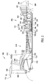
- FIG. 2 is cross-sectional view of a gas turbine engine 102 in accordance with an exemplary embodiment of the present disclosure.
- Engine 102 includes a fan assembly 202 including a containment 204 and a plurality of fan blades 206.
- Outlet guide vanes (OGV) 208 extend between aft fan case 210 and an inner casing 211.
- a fan frame 212 radially supports aft fan case 210.
- a four stage orthogonal booster 214 co-rotates with fan blades 206.
- a variable bypass valve (VBV) extends between fan struts 216.
- Engine 102 includes an engine inlet pressure sensor (P0) and an engine inlet temperature sensor (T12) that measure respective engine process parameters upstream of the fan at the engine inlet, and a compressor inlet temperature (CIT) probe T25 and a compressor inlet pressure port P25 located upstream from a high pressure compressor 218.
- P0 engine inlet pressure sensor
- T12 engine inlet temperature sensor
- CIT compressor inlet temperature
- a rear frame 231 of compressor 218 includes a combustor 230 and an igniter plug 232 with a fuel nozzle 234 and an outlet guide vane (OGV) 236. It includes a vent seal 238 and 4R/A/O seal 240 and 4R bearing 242 and 4B bearing 244. Rear frame 231 also includes a 5R bearing 246 and 5R/A/O seal 248, a diffuser 250 and pressure balance seal 252. Compressor rear frame 231 also includes a turbine stage 1 nozzle 254. A compressor discharge temperature (T3) sensor and a compressor discharge pressure (P3) port provide access to conditions at the compressor discharge.
- Engine 102 includes a high pressure turbine 260 and a low pressure turbine 262 that includes a 360° case 264, aerodynamic struts 266 that remove swirl from the exit gas and a turbine rear frame 268 formed as a one piece casting.
- the compressed air that is discharged from booster 214 is channeled through compressor 218 wherein the airflow is further compressed and delivered to combustor 230.
- Hot products of combustion (not shown) from combustor 230 are utilized to drive turbines 260 and 262, and turbine 262 is utilized to drive fan assembly 202 and booster 214 by way of a shaft 270.
- engine 102 Many of the components of engine 102 are monitored by process sensors and structural force sensors that generate signals during various flight modes including initial take-off, level flight and landing. Such signals are relayed via the EEC 108 an on-ground maintenance crew and/or separate remote engine data control center having its own processor.
- engine inlet pressure (P0) and an engine inlet temperature (T12), compressor discharge temperature (T3) sensor and a compressor discharge pressure (P3) are also used for estimating atmospheric water content.
- P0 engine inlet pressure
- T12 engine inlet temperature
- T3 compressor discharge temperature
- P3 compressor discharge pressure
- P3 compressor discharge pressure
- methods of various embodiments of the present disclosure use the equations of isentropic compression to compute a ratio of specific heats, a term which is known to those skilled in the art to mean the ratio of c P (specific heat at constant pressure) to c V (specific heat at constant volume).
- the methods then use the ratio of specific heats to determine the water content of the air for example, by using a look-up table.
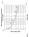
- Figure 3 is a graph 300 of a humidity ratio versus a ratio of specific heats that may be used with system 100 (shown in Figure 1 ).
- Graph 300 includes an x-axis 302 graduated in units of humidity ratio and a y-axis 304 graduated in units of a ratio of specific heats.
- Graph 300 includes a first trace 306 illustrating a relationship between humidity ratio and a ratio of specific heats at a temperature of approximately 180°C and a pressure of 0.5MPa.
- a second trace 308 illustrates a relationship between humidity ratio and a ratio of specific heats at a temperature of approximately 200°C and a pressure of 0.5MPa.
- a third trace 310 illustrates a relationship between humidity ratio and a ratio of specific heats at a temperature of approximately 240°C and a pressure of 0.5MPa.
- a forth trace 312 illustrates a relationship between humidity ratio and a ratio of specific heats at a temperature of approximately 280°C and a pressure of 0.5MPa, and a fifth trace 314 illustrates a relationship between humidity ratio and a ratio of specific heats at a temperature of approximately 320°C and a pressure of 0.5MPa.
- engine 102 operates using a Brayton cycle wherein the compression stage is isentropic.
- Equation (1) a relationship between humidity and the ratio of specific heats may be applied to determine humidity from measurements of pressure and temperature.
- ⁇ ln / P 1 P 2 ln / P 1 P 2 - ln / T 1 T 2
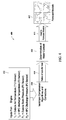
- Figure 4 is a data flow diagram 400 for determining water content in air using measured parameters from a gas turbine engine.
- a process receives inputs 402 of measured parameters of air temperature and static pressure of the ambient air surrounding for example, the gas turbine engine.
- the inputs for ambient air temperature and pressure are available from measured parameters from the existing T12 temperature sensor and the P0 pressure sensor, in the exemplary embodiment. In instances where these particular parameters are not measured directly, they may be derived by computing the parameter from other measured parameters.
- the process also receives inputs 402 of measured parameters of air temperature and static pressure of the compressed air exiting for example, high pressure compressor 218.
- Such parameters are also measured using existing engine performance sensors, T3 and P3, respectively. By using existing engine performance sensors, new additional sensors are not required to be added to the aircraft and are not mounted in the airstream surrounding the aircraft contributing to additional aircraft drag.
- T12, P0, T3, and P3 are used in the equations of isentropic compression 404 described above to determine a ratio of specific heats 406 and humidity ratio at the representative pressure and temperature.
- the processor in the EEC may perform such calculation or the T12, P0, T3, and P3 may be transmitted to a second processor for a determination of the ratio of specific heats and/or humidity ratio.
- a water content of the air surrounding aircraft 100 is determined 408 in real-time and transmitted to a weather facility where the determined water content is input 410 into weather prediction algorithms to generate forecast models 412 of future weather patterns.
- the computations described above can be performed in any of several places: within the Electronic Engine Controller, within another computing device aboard the aircraft, or in a computing device outside the aircraft that receives sensor data transmitted to aircraft 100.
- the sensor data may be stored aboard the aircraft along with time and location data from the aircraft navigation system so it can be retrieved and used to compute water content after the aircraft lands.
- FIG 5 is a map 500 of the United States 502 illustrating exemplary aircraft routes 504 between various airports 506 which can be used as collection points for weather data in accordance with system 100 (shown in Figure 1 ).
- Such routes 504 represent the potential data collection coverage for determining water content of the air.
- commercial aircraft enable water content to be continuously measured at low cost along ascents, descents, and routes 504 of flight in the United States 502 and similarly, worldwide. Aircraft traverse such routes multiple times during a given time period increasing the collection of water content data by several orders of magnitude compared to current balloon soundings.
- Improved water content measurements can substantially improve weather forecasts, with particular improvement for predicting the onset of severe storms driven by convective weather such as those driven by heat released by gas-liquid phase changes in moist air.
- Various embodiments of the present disclosure facilitates real-time and near-real time measurements of water content of the air that are useful for weather forecast models, particularly over the oceans and land masses where few sensors are currently available.
- Various aircraft operators such as airlines, federal or other national agencies, research institutions, foreign military alliances, and national military air forces benefit from accurate water forecasts for their operation.
- inaccurate weather forecasts can lead vessels into unsafe conditions or cause them to take inefficient routes.
Landscapes
- Environmental & Geological Engineering (AREA)
- Engineering & Computer Science (AREA)
- Life Sciences & Earth Sciences (AREA)
- Environmental Sciences (AREA)
- Atmospheric Sciences (AREA)
- Biodiversity & Conservation Biology (AREA)
- Ecology (AREA)
- Chemical & Material Sciences (AREA)
- General Physics & Mathematics (AREA)
- Health & Medical Sciences (AREA)
- Aviation & Aerospace Engineering (AREA)
- Analytical Chemistry (AREA)
- Biochemistry (AREA)
- General Health & Medical Sciences (AREA)
- Physics & Mathematics (AREA)
- Immunology (AREA)
- Pathology (AREA)
- Arrangements For Transmission Of Measured Signals (AREA)
- Combined Controls Of Internal Combustion Engines (AREA)
- Testing Or Calibration Of Command Recording Devices (AREA)
- Investigating Or Analyzing Materials Using Thermal Means (AREA)
Abstract
Description
- This disclosure relates generally to methods and systems for measuring atmospheric conditions and more particularly, to methods and systems for collecting atmospheric weather data using an aircraft.
- An important obstacle to improved forecasting is lack of data about water content in the troposphere. Water content of an air mass can change rapidly during storms, over moist soil, or over bodies of water such as oceans. An inability to track changes in water content in these and other areas contributes to inaccurate weather forecasts.
- Existing methods for detecting and quantifying water vapor are inadequate because they can only be implemented on a local scale over land thereby leaving vast gaps in global meteorological continuity. The largest gaps occur over oceans where most atmospheric conditions originate. Although the existing atmospheric sensing systems listed below exhibit high resolution capabilities on a local scale, it is not practical to deploy such systems on a global scale because they are expensive to implement or maintain on a global scale and they lack adequate temporal and/or spatial resolution for realistic use on a global scale.
- Currently, a primary source of water vapor measurements are ground-based humidity sensors and balloon-borne sensors called "radiosondes." Radiosonde data have high quality, but have relatively poor spatial and temporal resolution. The radiosonde, an expendable balloon-borne instrument package that relays temperature, humidity, and pressure data to a ground receiver by radio signals, is the traditional cornerstone of the worldwide operational weather analysis and prediction system through deployments twice daily at several hundred sites around the world. However, the twice daily radiosonde deployments are primarily over land and are sparsely distributed due to cost considerations. No above-ground measurements are available during intervals between launches or at locations far from radiosonde launch points. For these reasons, radiosonde data is too costly and localized to support high resolution global meteorology.
- A limited number of commercial air carriers presently provide real-time wind, pressure, temperature, and humidity readings around the world as part of a system called Aeronautical Communications Addressing and Reporting System (ACARS). Although the ACARS system provides about 10,000 readings per day world wide at a cost about 100 times less than the recurring cost of radiosondes, the vast majority of ACARS readings are around airports and along common flight paths at established cruise flight levels which limits the spatial scope of this otherwise valuable data.
- Earth-based Differential Absorption Lidar (DIAL) and Raman Lidar systems are used to provide wind and water vapor profiles in remote areas. However, such systems are not economic to install and maintain, they do not penetrate cloud cover, and the lasers used are highly energized and are therefore not eye-safe.
- Water vapor radiometers are instruments that measure microwave energy emitted by the atmosphere to estimate zenithal integrated water vapor. Integrated water vapor is a measure of the depth of liquid water that would result if a column of water vapor were condensed into liquid water. Zenithal integrated water vapor (IWV), also known as Precipitable Water Vapor (PWV), is the integrated water vapor in a vertical column directly overhead an Earth-based measuring device. Earth-based upward-looking water vapor radiometers estimate PWV by measuring radiative brightness temperatures against the cold background of space. However, upward-looking water vapor radiometers must be "tuned" to local conditions using independently obtained PWV data, and although they generally exhibit good temporal resolution in relatively clear atmospheric conditions, they provide only localized PWV over land. Further, unless properly equipped, upward-looking radiometers are virtually useless in rain. Alternatively, satellite-based, downward-looking radiometers perform well over water and consistent temperature land masses by viewing microwave emissions from the atmosphere and underlying Earth's surface. Although downward-looking radiometers generally exhibit good spatial resolution they exhibit poor temporal resolution and perform poorly over most land masses. In either case, water vapor radiometers as a whole are not practical for global scale meteorology due to their cost, limited view, and performance characteristics.
- Fourier Transform Infrared Radiometer (FTIR) systems can provide high resolution satellite-based and Earth-based temperature and water vapor profiles by using a recursive solution of the radiative transfer equation to provide a vertical profile from the ground up. Although this method can provide vertical resolution of several hundred meters to a kilometer in the lower troposphere, the system exhibits poor performance in the presence of cloud cover and infrared active gases such as tropospheric ozone.
- Unmanned Air Vehicles (UAV's) provide high resolution data in regions inaccessible to other systems discussed above. However, unmanned aircraft are too costly for continuous global sensing, they lack adequate spatial and temporal resolution, and are typically only justified in specialized research applications.
- Additional water content measurements are available from satellites and from a few specially-equipped airliners operated under a NASA program called Tropospheric Airborne Meteorological Data Reporting (TAMDAR). Satellite data are unreliable because it is difficult for satellites to correctly resolve the altitude profile of moisture, especially when clouds are present. TAMDAR uses humidity sensors mounted on the outside of small, regional airliners. These sensors continuously measure humidity and temperature as the aircraft ascend and descend through the troposphere. This provides better spatial and temporal resolution than radiosondes. Though this approach has been shown to be technically effective for improved weather forecasts in the northeastern US, the additional weight and drag and the need for FAA certification of each type of sensor package on each type of aircraft makes this solution costly, which has limited the expansion of existing systems to other regions.
- In one embodiment, a method of measuring atmospheric water content includes measuring a first air temperature and a first air pressure at a first location in a compressor, measuring a second air temperature and a second air pressure at a second location in the compressor, computing a ratio of specific heats from the first and second air temperatures and the first and second air pressures, and determining an atmospheric water content from the ratio of specific heats.
- In another embodiment, an atmospheric monitoring system includes a compressor and at least one compressor sensor coupled to the compressor, wherein the sensor is configured to acquire atmospheric data from air channeled through the compressor.
- In yet another embodiment, a method of forecasting weather includes acquiring atmospheric data from a gas turbine engine onboard an aircraft during flight, processing the atmospheric data to determine an amount of water content in the atmosphere, transmitting at least one of the atmospheric data and the amount of water content to a weather forecast model, and predicting weather based on either one or both datasets.
- In still another embodiment, a method of forecasting weather includes determining a specific heat of a volume of air at a first location in a gas turbine engine, determining a specific heat of the volume of air at a second location in the gas turbine engine, and determining a water content of the volume of air using the specific heat of the volume of air at the first location and the second location.
-
-
Figure 1 is a block diagram of an exemplary embodiment of a system for collecting weather related data and monitoring the performance of gas turbine engines mounted on an aircraft; -
Figure 2 is cross-sectional view of a gas turbine engine in accordance with an exemplary embodiment of the present disclosure; -
Figure 3 is a graph of a humidity ratio versus a ratio of specific heats that may be used with system shown inFigure 1 ; -
Figure 4 is a data flow diagram for determining water content in air using measured parameters from a gas turbine engine; and -
Figure 5 is a map of the United States illustrating exemplary aircraft routes between various airports which can be used as collection points for weather data in accordance with system shown inFigure 1 . -
Figure 1 is a block diagram of an exemplary embodiment of asystem 100 for collecting weather related data and monitoring the performance ofgas turbine engines aircraft 106. Although twoengines Figure 1 , it should be noted thataircraft 106 could have additional engines mounted thereon. Accordingly, data collection for such additional engines would be accomplished in a manner substantially similar to that forengines engines system 100 is described in connection with an aircraft only by way of example. In addition to aeronautical applications, the present disclosure is applicable to other applications of gas turbine engines, including marine and industrial applications. -
System 100 includes an electronic engine controller (EEC) 108, such as a full authority digital engine control (FADEC), although other controllers can be used, associated with eachengine data storage device 110. Conventionalengine data sensors 112 andaircraft data sensors 114 are provided to sense selected data parameters related to the operation and performance ofengines aircraft 106. Theengine data sensors 112 andaircraft data sensors 114 can comprise any group of sensors that monitor data parameters of interest. In addition to aircraft parameters such as ambient temperature, air speed and altitude, engine parameters typically include exhaust gas temperature, oil temperature, component temperatures such as high pressure turbine shroud temperature, engine fuel flow, core speed, an engine inlet pressure (P0) and an engine inlet temperature (T12) measured upstream of the fan at the engine inlet, and a compressor discharge temperature (T3) and a compressor discharge pressure (P3) measured downstream of the engine high pressure compressor, a turbine exhaust pressure, fan speed, and other engine parameters. - Each ECU 108 receives signals from corresponding
engine data sensors 112 and theaircraft data sensors 114 as is known in the art. In response to these and other inputs,ECUs 108 generate command signals to operate engine actuators, such as hydro-mechanical units (not shown) that meter the flow of fuel torespective engines ECU 108 also outputs data signals to aircraftdata storage device 110. Aircraftdata storage device 110, which can be any conventional device such as a flight data recorder, quick access recorder, or any other type of in-flight data storage device, has a relatively large data storage capacity for storing the data signals. Aircraftdata storage device 110 could also contain processing capability to analyze data in-flight and only send the necessary maintenance messages to an aircraft centralized maintenance computer (not shown). Aircraftdata storage device 110 also receives signals fromaircraft data sensors 114. -
System 100 includes an algorithm that processes the data signals for monitoring engine performance characteristics. The monitoring algorithm can be implemented in a number of ways. For example, the monitoring algorithm could be implemented on theECUs 108 wherein the data signals are processed as they are received by theECUs 108. Alternatively, the monitoring algorithm could be implemented on aircraftdata storage device 110. In this case, the data signals would be processed after being transferred to aircraftdata storage device 110. Another alternative is to implement the monitoring algorithm on aground station computer 116, such as personal or workstation computer. The data signals stored in aircraftdata storage device 110 during a flight are downloaded toground station computer 116 for processing. This transfer can be accomplished after the flight via acommunications link 118 including use of a removable computer-readable medium, such as a floppy disk, CD-ROM or other optical medium, magnetic tape or the like, or a multimode communication link that may include a wireless portion. It is also possible to remotely transmit the data signals directly toground station computer 116 during flight operations for real-time processing. The signals may also be sent to other vehicles and/or facilities such asother aircraft 120,ships 122, andsatellites 124 vialink 118. Additionally, each ofaircraft 120,ships 122, andsatellites 124 may communicate between each other usingseparate communication links 126. A continuous and contemporaneous relaying of atmospheric information betweenaircraft 106,ground station computer 116,other aircraft 120,satellites 124 andships 122, or other ocean-based vessels or structures constitutes in part an atmospheric data network accessible to a plurality of users world-wide. With any implementation, the monitoring algorithm can be stored on one unit, for example,ECU 108, aircraftdata storage device 110, orground station computer 116 and accessed from there, or alternatively, it could be accessed from a removable computer-readable medium inserted into the appropriate drive of the unit. The monitoring algorithm could also be accessed via the Internet or another computer network. As used herein, the term "computer-readable medium" refers generally to any medium from which stored data can be read by a computer or similar unit. This includes not only removable media such as the aforementioned floppy disk and CD-ROM, but also non-removable media such as a hard disk or integrated circuit memory device in eachECU 108, aircraftdata storage device 110, orground station computer 116. - Further examples of
ground station computer 116 include international weather services, National Oceanic and Atmospheric Administration (NOAA), national military weather services, international military weather services such as NATO and other alliances, the national weather service, and other commercial users of weather information. - During operation,
sensors 112 collect atmospheric information from at least one ofengines ground station computer 116,other aircraft 120,satellites 124 andships 122 to determine the atmospheric humidityconditions surrounding aircraft 106. By time and location stamping the atmospheric information at a plurality of positions along the various flight paths of the aircraft that are a part of system 100 a humidity profile of a large portion of the atmosphere can be determined.Aircraft 106 may preprocess at least a portion of the atmospheric information and may store the information on board or may transmit the information in real-time to be used byground station computer 116,other aircraft 120,satellites 124, and ships 122. - In the exemplary embodiment, the algorithm includes the capability of continuously determining atmospheric weather parameters by using one or more of
engines engines 102 and/or 104 are used as a humidity sensor to determine an amount of atmospheric water vapor content entering the engine and therefore the amount of atmospheric water vapor content in theair surrounding aircraft 106. In the exemplary embodiment, pressure (P) and temperature (T) measurements taken from the turbine engine's inlet and compressor stages are used to determine atmospheric water vapor content. The determined water content value and a time and location at which the measurements were made are transmitted to, for example,ground station computer 116 for assimilating humidity measurements into weather forecasts. -
Figure 2 is cross-sectional view of agas turbine engine 102 in accordance with an exemplary embodiment of the present disclosure.Engine 102 includes afan assembly 202 including acontainment 204 and a plurality offan blades 206. Outlet guide vanes (OGV) 208 extend betweenaft fan case 210 and aninner casing 211. Afan frame 212 radially supportsaft fan case 210. A four stageorthogonal booster 214 co-rotates withfan blades 206. A variable bypass valve (VBV) extends between fan struts 216.Engine 102 includes an engine inlet pressure sensor (P0) and an engine inlet temperature sensor (T12) that measure respective engine process parameters upstream of the fan at the engine inlet, and a compressor inlet temperature (CIT) probe T25 and a compressor inlet pressure port P25 located upstream from ahigh pressure compressor 218. - A
rear frame 231 ofcompressor 218 includes a combustor 230 and anigniter plug 232 with afuel nozzle 234 and an outlet guide vane (OGV) 236. It includes avent seal 238 and 4R/A/O seal 240 and 4R bearing 242 and 4B bearing 244.Rear frame 231 also includes a5R bearing 246 and 5R/A/O seal 248, adiffuser 250 andpressure balance seal 252. Compressorrear frame 231 also includes a turbine stage 1nozzle 254. A compressor discharge temperature (T3) sensor and a compressor discharge pressure (P3) port provide access to conditions at the compressor discharge.Engine 102 includes ahigh pressure turbine 260 and alow pressure turbine 262 that includes a 360°case 264,aerodynamic struts 266 that remove swirl from the exit gas and a turbinerear frame 268 formed as a one piece casting. - In operation, air flows through
fan assembly 202 and a first portion of the airflow is channeled throughbooster 214. The compressed air that is discharged frombooster 214 is channeled throughcompressor 218 wherein the airflow is further compressed and delivered to combustor 230. Hot products of combustion (not shown) from combustor 230 are utilized to driveturbines turbine 262 is utilized to drivefan assembly 202 andbooster 214 by way of ashaft 270. - Many of the components of
engine 102 are monitored by process sensors and structural force sensors that generate signals during various flight modes including initial take-off, level flight and landing. Such signals are relayed via theEEC 108 an on-ground maintenance crew and/or separate remote engine data control center having its own processor. - In the exemplary embodiment, engine inlet pressure (P0) and an engine inlet temperature (T12), compressor discharge temperature (T3) sensor and a compressor discharge pressure (P3) are also used for estimating atmospheric water content. As air traverses the compressor stages of the engine, its pressure and temperature increase. For air containing little water vapor, the value of the specific heat of the air, c, is low. For air containing more water vapor, the value of the specific heat of the air, c is relatively larger. As a result, a temperature rise for moist air flowing through the compressor is less than the temperature rise for dry air flowing through the compressor. For air containing water droplets or ice crystals, overall specific heat, c, is even higher: as the temperature rises, the ice melts and the water vaporizes. Such phase changes absorb large amounts of heat, so the temperature rise in the compressor is even less than the temperature rise for air with a large amount of water vapor.
- To convert pressure and temperature measurements into water content, methods of various embodiments of the present disclosure, for example, use the equations of isentropic compression to compute a ratio of specific heats, a term which is known to those skilled in the art to mean the ratio of cP (specific heat at constant pressure) to cV (specific heat at constant volume). The methods then use the ratio of specific heats to determine the water content of the air for example, by using a look-up table.
-
Figure 3 is agraph 300 of a humidity ratio versus a ratio of specific heats that may be used with system 100 (shown inFigure 1 ).Graph 300 includes anx-axis 302 graduated in units of humidity ratio and a y-axis 304 graduated in units of a ratio of specific heats.Graph 300 includes afirst trace 306 illustrating a relationship between humidity ratio and a ratio of specific heats at a temperature of approximately 180°C and a pressure of 0.5MPa. Asecond trace 308 illustrates a relationship between humidity ratio and a ratio of specific heats at a temperature of approximately 200°C and a pressure of 0.5MPa. Athird trace 310 illustrates a relationship between humidity ratio and a ratio of specific heats at a temperature of approximately 240°C and a pressure of 0.5MPa. Aforth trace 312 illustrates a relationship between humidity ratio and a ratio of specific heats at a temperature of approximately 280°C and a pressure of 0.5MPa, and afifth trace 314 illustrates a relationship between humidity ratio and a ratio of specific heats at a temperature of approximately 320°C and a pressure of 0.5MPa. - In the exemplary embodiment,
engine 102 operates using a Brayton cycle wherein the compression stage is isentropic. For isentropic compression, the following relationship between pressure and absolute temperature applies, where γ is the ratio of specific heats (γ = cp /cv ):
- If equation (1) is solved for γ, a relationship between humidity and the ratio of specific heats may be applied to determine humidity from measurements of pressure and temperature.

- The qualitative relationship between the ratio of specific heats and relative humidity is: as humidity increases, γ decreases. This relationship can be derived from the definition of the ratio of specific heats shown in Equation 3.

- For an ideal gas, enthalpy, h and internal energy, u can be expressed respectively as:

- Therefore, the ratio of specific heats can be rewritten as:

- The temperature term cancels, and the equation can be rewritten using the following relationships for specific enthalpy and specific energy in an air/water vapor mixture, where ω is the humidity ratio.

- The relationship between γ and the humidity ratio becomes:


- Values for hair, uair, hvapor, and uvapor can be obtained from the ideal gas tables for air and water vapor.
Figure 3 shows the results of the calculation in equation 7 for a representative pressure value of 0.5 MPa. In practice, equation 2 would be used to find γ from temperature and pressure. Then γ would be used to calculate ω via equation 8. -
Figure 4 is a data flow diagram 400 for determining water content in air using measured parameters from a gas turbine engine. A process receivesinputs 402 of measured parameters of air temperature and static pressure of the ambient air surrounding for example, the gas turbine engine. The inputs for ambient air temperature and pressure are available from measured parameters from the existing T12 temperature sensor and the P0 pressure sensor, in the exemplary embodiment. In instances where these particular parameters are not measured directly, they may be derived by computing the parameter from other measured parameters. The process also receivesinputs 402 of measured parameters of air temperature and static pressure of the compressed air exiting for example,high pressure compressor 218. Such parameters are also measured using existing engine performance sensors, T3 and P3, respectively. By using existing engine performance sensors, new additional sensors are not required to be added to the aircraft and are not mounted in the airstream surrounding the aircraft contributing to additional aircraft drag. - In the exemplary embodiment, T12, P0, T3, and P3 are used in the equations of
isentropic compression 404 described above to determine a ratio ofspecific heats 406 and humidity ratio at the representative pressure and temperature. The processor in the EEC may perform such calculation or the T12, P0, T3, and P3 may be transmitted to a second processor for a determination of the ratio of specific heats and/or humidity ratio. Using the on-board processors or off-board processors to determine the ratio of specific heats and humidity ratio a water content of theair surrounding aircraft 100 is determined 408 in real-time and transmitted to a weather facility where the determined water content isinput 410 into weather prediction algorithms to generateforecast models 412 of future weather patterns. - The computations described above can be performed in any of several places: within the Electronic Engine Controller, within another computing device aboard the aircraft, or in a computing device outside the aircraft that receives sensor data transmitted to
aircraft 100. The sensor data may be stored aboard the aircraft along with time and location data from the aircraft navigation system so it can be retrieved and used to compute water content after the aircraft lands. - Although the description above refers to the isentropic equations, it is understood the scope of the various embodiments of the present disclosure includes applying empirical corrections to the computed values to account for non-ideal behavior of the gas, or heat transfers in the engine compressor, which make the process not quite isentropic. Other embodiments of the present disclosure also include corrections for solid-to-liquid and liquid-to-gas phase changes when the sensed water content exceeds 100% relative humidity at ambient conditions.
-
Figure 5 is amap 500 of theUnited States 502 illustratingexemplary aircraft routes 504 betweenvarious airports 506 which can be used as collection points for weather data in accordance with system 100 (shown inFigure 1 ).Such routes 504 represent the potential data collection coverage for determining water content of the air. In the exemplary embodiment, commercial aircraft enable water content to be continuously measured at low cost along ascents, descents, androutes 504 of flight in theUnited States 502 and similarly, worldwide. Aircraft traverse such routes multiple times during a given time period increasing the collection of water content data by several orders of magnitude compared to current balloon soundings. Improved water content measurements can substantially improve weather forecasts, with particular improvement for predicting the onset of severe storms driven by convective weather such as those driven by heat released by gas-liquid phase changes in moist air. - Various embodiments of the present disclosure facilitates real-time and near-real time measurements of water content of the air that are useful for weather forecast models, particularly over the oceans and land masses where few sensors are currently available. Various aircraft operators such as airlines, federal or other national agencies, research institutions, foreign military alliances, and national military air forces benefit from accurate water forecasts for their operation. For oceanic operators such as the Navy or commercial ship operators, inaccurate weather forecasts can lead vessels into unsafe conditions or cause them to take inefficient routes.
- The above-described methods and systems for the continuous measurement of atmospheric water vapor by using an aircraft turbine engine as a humidity sensor are cost-effective and highly reliable. Pressure and temperature sensors in the engine's compressor reveal how much the temperature rises as incoming air is squeezed to higher pressure. For air containing more water vapor, the temperature rises less. Measuring the temperature and pressure at two points in the engine compressor permits computing the moisture content of the air. Because modem turbine engines already have appropriate sensors, no modification to existing aircraft engine mechanical systems is required, as only a software modification is necessary, substantially eliminating any weight or drag penalty. Accordingly, the methods and systems facilitate acquisition of weather related data in a cost-effective and reliable manner.
- While the disclosure has been described in terms of various specific embodiments, those skilled in the art will recognize that the disclosure can be practiced with modification within the scope of the claims.
- The following is a non-exhaustive list of Embodiments that may or may not be claimed.
- 1. A method (400) of forecasting weather comprising:
- acquiring (402) atmospheric data from a gas turbine engine (102,104) onboard an aircraft during flight;
- processing (404,408) the atmospheric data to determine an amount of water content in the atmosphere;
- transmitting (410) at least one of the atmospheric data and the amount of water content to a weather forecast model (412); and
- predicting weather based on the at least one of the atmospheric data and the amount of water content.
- 2. A method in accordance with Embodiment 1 wherein acquiring atmospheric data comprises acquiring atmospheric data using a sensor (112) configured to monitor process parameters of the gas turbine engine.
- 3. A method in accordance with Embodiments 1 or 2 wherein acquiring atmospheric data comprises acquiring atmospheric data from at least a portion of the ambient air entering the gas turbine engine.
- 4. A method in accordance with any of Embodiments 1-3 wherein acquiring atmospheric data comprises acquiring at least one of a compressor inlet temperature, a compressor inlet pressure, a compressor discharge temperature, and compressor discharge pressure.
- 5. A method in accordance with any of Embodiments 1-4 wherein processing the atmospheric data comprises determining a ratio of specific heats (406) of air channeled through the gas turbine engine.
- 6. A method in accordance with Embodiment 5 wherein processing the atmospheric data comprises determining a humidity ratio from the ratio of specific heats.
- 7. A method in accordance with Embodiment 6 wherein determining a humidity ratio comprises determining a water content of the air.
- 8. A method in accordance with Embodiment 7 wherein determining a water content of the air comprises determining the water content of the air using a look-up table.
- 9. A method in accordance with any of Embodiments 1-8 further comprising stamping the atmospheric data with a time and an aircraft location when the data was acquired.
- 10. A method in accordance with any of Embodiments 1-9 further comprising storing the atmospheric data with a time and an aircraft location when the data was acquired on board the aircraft for future download.
- 11. A method in accordance with any of Embodiments 1-10 further comprising receiving atmospheric data at the weather forecast model from a source other than a gas turbine engine.
- 12. A method in accordance with any of Embodiments 1-11 wherein transmitting at least one of the atmospheric data and the amount of water content to a weather forecast model comprises transmitting the at least one of the atmospheric data and the amount of water content from the aircraft to the forecast model through a multi-mode network (116,120,122,124).
- 13. A method of forecasting weather (400) comprising:
- determining a specific heat (406) of a volume of air in a gas turbine engine (102,104); and
- determining a water content (408) of the volume of air using the specific heat of the volume of air.
- 14. A method in accordance with Embodiment 13 wherein determining a specific heat of a volume of air comprises measuring a first air temperature and a first air pressure at the first location.
- 15. A method in accordance with Embodiment 14 wherein determining a specific heat of a volume of air comprises measuring a second air temperature and a second air pressure at the second location.
- 16. A method in accordance with any of Embodiments 13-15 wherein determining a water content of the volume of air comprises computing a ratio of specific heats from the first and second air temperatures and the first and second air pressures.
- 17. A method in accordance with Embodiment 16 wherein determining an atmospheric water content from the ratio of specific heats comprises using a lookup table.
- 18. An atmospheric monitoring system comprising:
- a compressor (218); and
- at least one performance sensor coupled to said compressor, said sensor configured to acquire atmospheric data from air channeled through said compressor.
- 19. A system in accordance with Embodiment 18 wherein said compressor is at least one of a portion of a turbine engine and a supercharger.
- 20. A system in accordance with Embodiments 18 or 19 wherein said at least one sensor comprises at least one of a temperature sensor and a pressure sensor.
- 21. A system in accordance with Embodiment 20 wherein said at least one sensor comprises at least one of a compressor inlet temperature sensor and a compressor inlet pressure sensor.
- 22. A system in accordance with Embodiment 20wherein said at least one sensor comprises at least one of a compressor discharge temperature sensor and a compressor discharge pressure sensor.
- 23. A system in accordance with any of Embodiments 18-22 further comprising a processor communicatively coupled to said at least one sensor, said processor configured to:
- compute a ratio of specific heats from the acquired atmospheric data; and
- determine an atmospheric water content from the ratio of specific heats.
- 24. A system in accordance with Embodiment 23 wherein said processor is configured to assume ideal gas behavior and isentropic compression of the air channeled through the engine.
- 25. A system in accordance with Embodiments 23 or 24 wherein said processor is configured to correct for non-ideal gas behavior of the air channeled through the engine.
- 26. A system in accordance with any of Embodiments 23-25 wherein said processor is configured to determine an atmospheric water content from the ratio of specific heats using a look-up table.
- 27. A system in accordance with Embodiment 26 wherein said processor is configured to determine an atmospheric water content from the ratio of specific heats using a look-up table relating a ratio of specific heats to a humidity ratio.
- 28. A system in accordance with any of Embodiments 18-27 further comprising a processor communicatively coupled to said at least one sensor, said processor configured to correct for non-isentropic compression.
- 29. A system in accordance with any of Embodiments 18-28 further comprising a processor communicatively coupled to said at least one sensor, said processor configured to receive a first air temperature and a first air pressure measured at a first location that is upstream from the compressor.
- 30. A system in accordance with Embodiment 29 wherein said processor configured to receive a second air temperature and a second air pressure measured at a second location that is downstream from at least one of a compressor and a compressor stage.
- 31. A system in accordance with
Embodiment 30 wherein said processor is configured to:- record a time and a location of a measurement of at least one of the first air temperature, the second air temperature, the first air pressure, and the second air pressure wherein the measurements are made substantially simultaneously; and
- transmit each of the measurements, the respective time, and the respective location to a weather forecast model.
- 32. A system in accordance with Embodiment 31 further comprising a weather forecast model to generate a weather forecast using the measurement of at least one of the first air temperature, the second air temperature, the first air pressure, and the second air pressure, a ratio of specific heats derived therefrom, and a humidity ratio derived therefrom.
- 33. A system in accordance with Embodiment 32 wherein said weather forecast model is configured to receive atmospheric measurements from a plurality of times and locations wherein the additional atmospheric measurements are acquired from other than the compressor.
Claims (15)
- A method (400) of forecasting weather comprising:acquiring (402) atmospheric data from a gas turbine engine (102,104) onboard an aircraft during flight;processing (404,408) the atmospheric data to determine an amount of water content in the atmosphere;transmitting (410) at least one of the atmospheric data and the amount of water content to a weather forecast model (412); andpredicting weather based on the at least one of the atmospheric data and the amount of water content.
- A method in accordance with Claim 1 wherein acquiring atmospheric data comprises:i. acquiring atmospheric data using a sensor (112) configured to monitor process parameters of the gas turbine engine; and/orii. acquiring atmospheric data from at least a portion of the ambient air entering the gas turbine engine; and/oriii. acquiring at least one of a compressor inlet temperature, a compressor inlet pressure, a compressor discharge temperature, and compressor discharge pressure.
- A method in accordance with Claim 1 or Claim 2 wherein processing the atmospheric data comprises:i. determining a ratio of specific heats (406) of air channeled through the gas turbine engine; and/orii. determining a humidity ratio from the ratio of specific heats, which preferably comprises determining a water content of the air, which preferably comprises determining the water content of the air using a look-up table.
- A method in accordance with any of Claims 1-3 further comprising stamping the atmospheric data with a time and an aircraft location when the data was acquired.
- A method in accordance with any of Claims 1-4 further comprising storing the atmospheric data with a time and an aircraft location when the data was acquired on board the aircraft for future download.
- A method in accordance with any of Claims 1-5 further comprising receiving atmospheric data at the weather forecast model from a source other than a gas turbine engine.
- A method in accordance with any of Claims 1-6 wherein transmitting at least one of the atmospheric data and the amount of water content to a weather forecast model comprises transmitting the at least one of the atmospheric data and the amount of water content from the aircraft to the forecast model through a multi-mode network (116,120,122,124).
- An atmospheric monitoring system comprising:a compressor (218), which is preferably at least one of a portion of a turbine engine anda supercharger; andat least one performance sensor coupled to said compressor, said sensor configured to acquire atmospheric data from air channeled through said compressor.
- A system in accordance with Claim 8 wherein said at least one sensor comprises at least one of a temperature sensor, preferably one of a compressor inlet or compressor discharge temperature sensor, and a pressure sensor, preferably one of a compressor inlet or compressor discharge pressure sensor.
- A system in accordance with Claim 8 or Claim 9 further comprising a processor communicatively coupled to said at least one sensor, said processor configured to:compute a ratio of specific heats from the acquired atmospheric data; anddetermine an atmospheric water content from the ratio of specific heats.
- A system in accordance with Claim 10 wherein said processor is configured to assume ideal gas behavior and isentropic compression of the air channeled through the engine; and/or correct for non-ideal gas behavior of the air channeled through the engine.
- A system in accordance with Claims 10 or 11 wherein said processor is configured to determine an atmospheric water content from the ratio of specific heats using a look-up table, which preferably relates a ratio of specific heats to a humidity ratio.
- A system in accordance with any of Claims 8 to 12 further comprising a processor communicatively coupled to said at least one sensor, said processor configured to:i. correct for non-isentropic compression; and/orii. receive a first air temperature and a first air pressure measured at a first location that is upstream from the compressor; and/oriii. receive a second air temperature and a second air pressure measured at a second location that is downstream from at least one of a compressor and a compressor stage.
- A system in accordance with Claim 13 wherein said processor is configured to:record a time and a location of a measurement of at least one of the first air temperature, the second air temperature, the first air pressure, and the second air pressure wherein the measurements are made substantially simultaneously; andtransmit each of the measurements, the respective time, and the respective location to a weather forecast model.
- A system in accordance with Claim 14 further comprising a weather forecast model to generate a weather forecast using the measurement of at least one of the first air temperature, the second air temperature, the first air pressure, and the second air pressure, a ratio of specific heats derived therefrom, and a humidity ratio derived therefrom, wherein said weather forecast model is preferably configured to receive atmospheric measurements from a plurality of times and locations wherein the additional atmospheric measurements are acquired from other than the compressor.
Applications Claiming Priority (3)
| Application Number | Priority Date | Filing Date | Title |
|---|---|---|---|
| US11/668,956 US7698927B2 (en) | 2007-01-30 | 2007-01-30 | Methods and systems for measuring atmospheric water content |
| PCT/US2007/088302 WO2008094363A1 (en) | 2007-01-30 | 2007-12-20 | Method and system for forescating weather using atmospheric water measured onboard an aircraft |
| EP07869617.6A EP2115498B1 (en) | 2007-01-30 | 2007-12-20 | Method for forescating weather comprising determining atmospheric water content |
Related Parent Applications (2)
| Application Number | Title | Priority Date | Filing Date |
|---|---|---|---|
| EP07869617.6A Division EP2115498B1 (en) | 2007-01-30 | 2007-12-20 | Method for forescating weather comprising determining atmospheric water content |
| EP07869617.6A Division-Into EP2115498B1 (en) | 2007-01-30 | 2007-12-20 | Method for forescating weather comprising determining atmospheric water content |
Publications (2)
| Publication Number | Publication Date |
|---|---|
| EP3032290A1 true EP3032290A1 (en) | 2016-06-15 |
| EP3032290B1 EP3032290B1 (en) | 2019-06-26 |
Family
ID=39400486
Family Applications (2)
| Application Number | Title | Priority Date | Filing Date |
|---|---|---|---|
| EP07869617.6A Active EP2115498B1 (en) | 2007-01-30 | 2007-12-20 | Method for forescating weather comprising determining atmospheric water content |
| EP15202553.2A Active EP3032290B1 (en) | 2007-01-30 | 2007-12-20 | Method and system for forescating weather using atmospheric water content measured onboard an aircraft |
Family Applications Before (1)
| Application Number | Title | Priority Date | Filing Date |
|---|---|---|---|
| EP07869617.6A Active EP2115498B1 (en) | 2007-01-30 | 2007-12-20 | Method for forescating weather comprising determining atmospheric water content |
Country Status (5)
| Country | Link |
|---|---|
| US (3) | US7698927B2 (en) |
| EP (2) | EP2115498B1 (en) |
| JP (2) | JP5208969B2 (en) |
| CA (1) | CA2673818C (en) |
| WO (1) | WO2008094363A1 (en) |
Cited By (1)
| Publication number | Priority date | Publication date | Assignee | Title |
|---|---|---|---|---|
| RU181160U1 (en) * | 2017-12-08 | 2018-07-05 | Федеральное государственное бюджетное учреждение науки Институт оптики атмосферы им. В.Е. Зуева Сибирского отделения Российской академии наук (ИОА СО РАН) | LIDAR FOR OZONE PROBING IN THE UPPER TROPOSPHERE - THE LOWER STRATOSPHERE |
Families Citing this family (25)
| Publication number | Priority date | Publication date | Assignee | Title |
|---|---|---|---|---|
| DE102007008296A1 (en) * | 2007-02-16 | 2008-08-21 | Alstom Technology Ltd. | Method for automatically controlling one or more firing temperatures of a gas turbine plant and method for determining the water content in the exhaust gas of a gas turbine plant |
| US8437893B2 (en) * | 2007-03-16 | 2013-05-07 | The Boeing Company | Determining current meteorological conditions specific to an aircraft |
| GB0710162D0 (en) * | 2007-05-26 | 2007-07-04 | Rolls Royce Plc | Method and apparatus for suppressing aeroengine contrails |
| WO2009045218A1 (en) | 2007-10-04 | 2009-04-09 | Donovan John J | A video surveillance, storage, and alerting system having network management, hierarchical data storage, video tip processing, and vehicle plate analysis |
| US8013738B2 (en) | 2007-10-04 | 2011-09-06 | Kd Secure, Llc | Hierarchical storage manager (HSM) for intelligent storage of large volumes of data |
| US7872603B2 (en) * | 2008-09-04 | 2011-01-18 | The Boeing Company | Method and apparatus for making airborne radar horizon measurements to measure atmospheric refractivity profiles |
| US8314730B1 (en) | 2010-12-14 | 2012-11-20 | The Boeing Company | Collection of meteorological data by vehicles |
| US8839663B2 (en) * | 2012-01-03 | 2014-09-23 | General Electric Company | Working fluid sensor system for power generation system |
| US20140026999A1 (en) * | 2012-07-25 | 2014-01-30 | Solar Turbines Incorporated | Exhaust diffuser for a gas turbine engine having curved and offset struts |
| US8787904B1 (en) * | 2013-03-12 | 2014-07-22 | Smartsky Networks LLC | Aircraft based wireless communication system |
| WO2014174340A1 (en) * | 2013-04-22 | 2014-10-30 | Chad Klippert | Aircraft flight data monitoring and reporting system and use thereof |
| US9596020B2 (en) | 2014-08-18 | 2017-03-14 | Sunlight Photonics Inc. | Methods for providing distributed airborne wireless communications |
| US11968022B2 (en) | 2014-08-18 | 2024-04-23 | Sunlight Aerospace Inc. | Distributed airborne wireless communication services |
| US9083425B1 (en) * | 2014-08-18 | 2015-07-14 | Sunlight Photonics Inc. | Distributed airborne wireless networks |
| US9302782B2 (en) | 2014-08-18 | 2016-04-05 | Sunlight Photonics Inc. | Methods and apparatus for a distributed airborne wireless communications fleet |
| KR101660865B1 (en) * | 2015-06-30 | 2016-09-28 | 대한민국 | Apparatus for acquiring meteorological data using meteorological sensors |
| US10470114B2 (en) * | 2016-06-30 | 2019-11-05 | General Electric Company | Wireless network selection |
| US10071820B2 (en) * | 2016-09-19 | 2018-09-11 | Pratt & Whitney Canada Corp. | Inclement weather detection for aircraft engines |
| US11913643B2 (en) * | 2019-04-17 | 2024-02-27 | Rtx Corporation | Engine wireless sensor system with energy harvesting |
| EP3726324B1 (en) | 2019-04-17 | 2023-03-01 | Raytheon Technologies Corporation | Gas turbine engine communication gateway with internal sensors |
| EP3726323B1 (en) | 2019-04-17 | 2023-03-08 | Raytheon Technologies Corporation | Gas turbine engine communication gateway with integral antennas |
| GB2584499C (en) * | 2019-06-28 | 2021-10-20 | Satavia Ltd | System and method for generating an aircraft flight trajectory |
| CN112632473B (en) * | 2021-03-09 | 2021-05-25 | 长江空间信息技术工程有限公司(武汉) | Calculation method for ground and space-based GNSS (Global navigation satellite System) combined atmospheric degradable water volume |
| CN114386860B (en) * | 2022-01-14 | 2022-11-29 | 西安理工大学 | Method for determining regional atmospheric precipitation pattern index |
| US12215634B1 (en) * | 2023-11-21 | 2025-02-04 | General Electric Company | Turbine engine including a steam system |
Citations (2)
| Publication number | Priority date | Publication date | Assignee | Title |
|---|---|---|---|---|
| US4028942A (en) * | 1976-01-19 | 1977-06-14 | Gardiner Frank J | Hygrometer |
| EP1717553A2 (en) * | 2005-04-29 | 2006-11-02 | United Technologies Corporation | Methods and systems for monitoring atmospheric conditions, predicting turbulent atmospheric conditions and optimizing flight paths of aircraft |
Family Cites Families (24)
| Publication number | Priority date | Publication date | Assignee | Title |
|---|---|---|---|---|
| US3083528A (en) | 1959-05-12 | 1963-04-02 | Raytheon Co | Microwave engines |
| US3369361A (en) * | 1966-03-07 | 1968-02-20 | Gale M. Craig | Gas turbine power plant with sub-atmospheric spray-cooled turbine discharge into exhaust compressor |
| US3825211A (en) | 1972-06-19 | 1974-07-23 | Phaser Telepropulsion Inc | Laser rocket |
| US3818700A (en) | 1972-10-20 | 1974-06-25 | Avco Corp | Ram jet powered by a laser beam |
| US4036012A (en) | 1976-02-18 | 1977-07-19 | The United States Of America As Represented By The Secretary Of The Army | Laser powered rocket engine using a gasdynamic window |
| US4614405A (en) | 1982-09-28 | 1986-09-30 | The Boeing Company | Wide angle laser window |
| ATE31964T1 (en) * | 1983-03-02 | 1988-01-15 | Cosworth Eng | COMBUSTION ENGINE. |
| JP2692341B2 (en) * | 1990-06-07 | 1997-12-17 | トヨタ自動車株式会社 | Two-shaft gas turbine engine |
| US5542247A (en) | 1994-06-24 | 1996-08-06 | Lockheed Corporation | Apparatus powered using laser supplied energy |
| US6563452B1 (en) * | 1998-07-06 | 2003-05-13 | Honeywell International Inc. | Apparatus and method for determining wind profiles and for predicting clear air turbulence |
| JP4517259B2 (en) * | 2000-06-20 | 2010-08-04 | 株式会社Ihi | Method for detecting disconnection of thermocouple provided in gas turbine |
| JP2003161504A (en) * | 2001-11-26 | 2003-06-06 | Osaka Gas Co Ltd | Processing equipment |
| JP3679065B2 (en) * | 2002-03-29 | 2005-08-03 | 株式会社ユー・ドム | Gas concentration measurement device in the atmosphere |
| US7175136B2 (en) * | 2003-04-16 | 2007-02-13 | The Boeing Company | Method and apparatus for detecting conditions conducive to ice formation |
| US6943699B2 (en) * | 2003-07-23 | 2005-09-13 | Harris Corporation | Wireless engine monitoring system |
| US6937937B1 (en) * | 2004-05-28 | 2005-08-30 | Honeywell International Inc. | Airborne based monitoring |
| US7069147B2 (en) * | 2004-05-28 | 2006-06-27 | Honeywell International Inc. | Airborne based monitoring |
| US6977608B1 (en) * | 2004-12-15 | 2005-12-20 | Rockwell Collins | Atmospheric data aggregation and forecasting system |
| US20060168090A1 (en) * | 2005-01-07 | 2006-07-27 | United Technologies Corporation | Remote integrated subsystems in an aircraft or the like |
| US7448359B2 (en) * | 2006-08-10 | 2008-11-11 | Ford Global Technologies, Llc | Multi-mode internal combustion engine |
| US7213566B1 (en) * | 2006-08-10 | 2007-05-08 | Ford Global Technologies, Llc | Engine system and method of control |
| US20080197238A1 (en) | 2007-02-15 | 2008-08-21 | Young Kun Bae | Photonic laser-based propulsion having an active intracavity thrust amplification system |
| RU2398717C1 (en) | 2009-01-13 | 2010-09-10 | Александр Олегович Майборода | Method to deliver cargoes in space and device to this end |
| US20130061571A1 (en) | 2011-09-14 | 2013-03-14 | Robert Van Burdine | Laser propelled flight vehicle |
-
2007
- 2007-01-30 US US11/668,956 patent/US7698927B2/en active Active
- 2007-12-20 EP EP07869617.6A patent/EP2115498B1/en active Active
- 2007-12-20 WO PCT/US2007/088302 patent/WO2008094363A1/en not_active Ceased
- 2007-12-20 JP JP2009548243A patent/JP5208969B2/en active Active
- 2007-12-20 CA CA2673818A patent/CA2673818C/en active Active
- 2007-12-20 EP EP15202553.2A patent/EP3032290B1/en active Active
-
2010
- 2010-03-05 US US12/718,519 patent/US8051701B2/en active Active
-
2011
- 2011-09-23 US US13/243,003 patent/US8813541B1/en active Active
-
2012
- 2012-09-21 JP JP2012208352A patent/JP5782417B2/en active Active
Patent Citations (2)
| Publication number | Priority date | Publication date | Assignee | Title |
|---|---|---|---|---|
| US4028942A (en) * | 1976-01-19 | 1977-06-14 | Gardiner Frank J | Hygrometer |
| EP1717553A2 (en) * | 2005-04-29 | 2006-11-02 | United Technologies Corporation | Methods and systems for monitoring atmospheric conditions, predicting turbulent atmospheric conditions and optimizing flight paths of aircraft |
Cited By (1)
| Publication number | Priority date | Publication date | Assignee | Title |
|---|---|---|---|---|
| RU181160U1 (en) * | 2017-12-08 | 2018-07-05 | Федеральное государственное бюджетное учреждение науки Институт оптики атмосферы им. В.Е. Зуева Сибирского отделения Российской академии наук (ИОА СО РАН) | LIDAR FOR OZONE PROBING IN THE UPPER TROPOSPHERE - THE LOWER STRATOSPHERE |
Also Published As
| Publication number | Publication date |
|---|---|
| US8051701B2 (en) | 2011-11-08 |
| JP2010517053A (en) | 2010-05-20 |
| JP2013040950A (en) | 2013-02-28 |
| CA2673818A1 (en) | 2008-08-07 |
| EP3032290B1 (en) | 2019-06-26 |
| JP5782417B2 (en) | 2015-09-24 |
| WO2008094363A1 (en) | 2008-08-07 |
| CA2673818C (en) | 2018-03-06 |
| JP5208969B2 (en) | 2013-06-12 |
| EP2115498A1 (en) | 2009-11-11 |
| EP2115498B1 (en) | 2016-03-09 |
| US20100154512A1 (en) | 2010-06-24 |
| US8813541B1 (en) | 2014-08-26 |
| US7698927B2 (en) | 2010-04-20 |
| US20080178659A1 (en) | 2008-07-31 |
Similar Documents
| Publication | Publication Date | Title |
|---|---|---|
| EP3032290B1 (en) | Method and system for forescating weather using atmospheric water content measured onboard an aircraft | |
| Gultepe et al. | A review of coastal fog microphysics during C-FOG | |
| Sausen et al. | A Diagnostic Study of the Global Distribution of Contrails Part I: Present Day Climateast | |
| Serke et al. | Supercooled liquid water content profiling case studies with a new vibrating wire sonde compared to a ground-based microwave radiometer | |
| Giez et al. | Static pressure from aircraft trailing-cone measurements and numerical weather-prediction analysis | |
| Bärfuss et al. | Drone-based meteorological observations up to the tropopause–a concept study | |
| US20120173147A1 (en) | Device and Method for Determining and Indicating Climate-Relevant Effects of a Contrail Produced by an Airplane | |
| Bouchard et al. | Relationship between airborne electrical and total water content measurements in ice clouds | |
| Desjardins et al. | Aircraft-based flux density measurements | |
| Haghighi et al. | High-altitude balloon-launched uncrewed aircraft system measurements of atmospheric turbulence and qualitative comparison with infrasound microphone response | |
| Vömel et al. | Aircraft dropsonde campaigns | |
| Altstädter et al. | ALADINA–an unmanned research aircraft for observing vertical and horizontal distributions of ultrafine particles within the atmospheric boundary layer | |
| Ryerson | Remote Sensing of In-Flight Icing Conditions Operational, Meteorological, and Technological Considerations | |
| Gao et al. | Variational bias correction of TAMDAR temperature observations in the WRF data assimilation system | |
| Moninger et al. | 4.2 AUTOMATED WEATHER REPORTS FROM AIRCRAFT: TAMDAR AND THE US AMDAR FLEET | |
| Rodríguez-Sanz et al. | Total air temperature anomalies as a metric for detecting high-altitude ice crystal events: Development of a failure indicator heuristic | |
| Aberson et al. | Aircraft observations of tropical cyclones | |
| Schumann et al. | Use of Numerical Weather Prediction Analysis for Testing Pressure Altitude Measurements on Aircraft-An Application Example | |
| Ryerson | Aircraft icing remote sensing | |
| Shull | A Validation Study of the Air Force Weather Agency (AFWA) JETRAX Contrail Forecast Algorithm. | |
| May et al. | Tropical warm pool international cloud experiment (TWP-ICE): Cloud and rain characteristics in the Australian Monsoon | |
| Yıldız et al. | İklim değişikliğinin sıcaklık yükselişine etkileri ve motor performansının değerlendirilmesi | |
| Wilfong, Sr et al. | Upper air data systems to support space launch range activities | |
| Schoenung et al. | Remote Sensing in the Arctic Using Autonomous Sensors Developed under NASA’s Airborne Science Program for the International Polar Year | |
| Spieß et al. | The Role of the Helicopter-Borne Turbulence Probe Helipod in Joint Field Campaigns |
Legal Events
| Date | Code | Title | Description |
|---|---|---|---|
| PUAI | Public reference made under article 153(3) epc to a published international application that has entered the european phase |
Free format text: ORIGINAL CODE: 0009012 |
|
| AC | Divisional application: reference to earlier application |
Ref document number: 2115498 Country of ref document: EP Kind code of ref document: P |
|
| AK | Designated contracting states |
Kind code of ref document: A1 Designated state(s): AT BE BG CH CY CZ DE DK EE ES FI FR GB GR HU IE IS IT LI LT LU LV MC MT NL PL PT RO SE SI SK TR |
|
| STAA | Information on the status of an ep patent application or granted ep patent |
Free format text: STATUS: REQUEST FOR EXAMINATION WAS MADE |
|
| 17P | Request for examination filed |
Effective date: 20161124 |
|
| RBV | Designated contracting states (corrected) |
Designated state(s): AT BE BG CH CY CZ DE DK EE ES FI FR GB GR HU IE IS IT LI LT LU LV MC MT NL PL PT RO SE SI SK TR |
|
| STAA | Information on the status of an ep patent application or granted ep patent |
Free format text: STATUS: EXAMINATION IS IN PROGRESS |
|
| 17Q | First examination report despatched |
Effective date: 20171207 |
|
| GRAP | Despatch of communication of intention to grant a patent |
Free format text: ORIGINAL CODE: EPIDOSNIGR1 |
|
| STAA | Information on the status of an ep patent application or granted ep patent |
Free format text: STATUS: GRANT OF PATENT IS INTENDED |
|
| INTG | Intention to grant announced |
Effective date: 20180621 |
|
| GRAJ | Information related to disapproval of communication of intention to grant by the applicant or resumption of examination proceedings by the epo deleted |
Free format text: ORIGINAL CODE: EPIDOSDIGR1 |
|
| STAA | Information on the status of an ep patent application or granted ep patent |
Free format text: STATUS: EXAMINATION IS IN PROGRESS |
|
| INTC | Intention to grant announced (deleted) | ||
| GRAP | Despatch of communication of intention to grant a patent |
Free format text: ORIGINAL CODE: EPIDOSNIGR1 |
|
| STAA | Information on the status of an ep patent application or granted ep patent |
Free format text: STATUS: GRANT OF PATENT IS INTENDED |
|
| INTG | Intention to grant announced |
Effective date: 20190115 |
|
| GRAS | Grant fee paid |
Free format text: ORIGINAL CODE: EPIDOSNIGR3 |
|
| GRAA | (expected) grant |
Free format text: ORIGINAL CODE: 0009210 |
|
| STAA | Information on the status of an ep patent application or granted ep patent |
Free format text: STATUS: THE PATENT HAS BEEN GRANTED |
|
| AC | Divisional application: reference to earlier application |
Ref document number: 2115498 Country of ref document: EP Kind code of ref document: P |
|
| AK | Designated contracting states |
Kind code of ref document: B1 Designated state(s): AT BE BG CH CY CZ DE DK EE ES FI FR GB GR HU IE IS IT LI LT LU LV MC MT NL PL PT RO SE SI SK TR |
|
| REG | Reference to a national code |
Ref country code: GB Ref legal event code: FG4D |
|
| REG | Reference to a national code |
Ref country code: CH Ref legal event code: EP |
|
| REG | Reference to a national code |
Ref country code: AT Ref legal event code: REF Ref document number: 1148943 Country of ref document: AT Kind code of ref document: T Effective date: 20190715 |
|
| REG | Reference to a national code |
Ref country code: DE Ref legal event code: R096 Ref document number: 602007058716 Country of ref document: DE |
|
| REG | Reference to a national code |
Ref country code: IE Ref legal event code: FG4D |
|
| REG | Reference to a national code |
Ref country code: NL Ref legal event code: MP Effective date: 20190626 |
|
| PG25 | Lapsed in a contracting state [announced via postgrant information from national office to epo] |
Ref country code: SE Free format text: LAPSE BECAUSE OF FAILURE TO SUBMIT A TRANSLATION OF THE DESCRIPTION OR TO PAY THE FEE WITHIN THE PRESCRIBED TIME-LIMIT Effective date: 20190626 Ref country code: FI Free format text: LAPSE BECAUSE OF FAILURE TO SUBMIT A TRANSLATION OF THE DESCRIPTION OR TO PAY THE FEE WITHIN THE PRESCRIBED TIME-LIMIT Effective date: 20190626 Ref country code: LT Free format text: LAPSE BECAUSE OF FAILURE TO SUBMIT A TRANSLATION OF THE DESCRIPTION OR TO PAY THE FEE WITHIN THE PRESCRIBED TIME-LIMIT Effective date: 20190626 |
|
| REG | Reference to a national code |
Ref country code: LT Ref legal event code: MG4D |
|
| PG25 | Lapsed in a contracting state [announced via postgrant information from national office to epo] |
Ref country code: BG Free format text: LAPSE BECAUSE OF FAILURE TO SUBMIT A TRANSLATION OF THE DESCRIPTION OR TO PAY THE FEE WITHIN THE PRESCRIBED TIME-LIMIT Effective date: 20190926 Ref country code: GR Free format text: LAPSE BECAUSE OF FAILURE TO SUBMIT A TRANSLATION OF THE DESCRIPTION OR TO PAY THE FEE WITHIN THE PRESCRIBED TIME-LIMIT Effective date: 20190927 Ref country code: LV Free format text: LAPSE BECAUSE OF FAILURE TO SUBMIT A TRANSLATION OF THE DESCRIPTION OR TO PAY THE FEE WITHIN THE PRESCRIBED TIME-LIMIT Effective date: 20190626 |
|
| REG | Reference to a national code |
Ref country code: DE Ref legal event code: R082 Ref document number: 602007058716 Country of ref document: DE Representative=s name: MAIER, LL.M., MICHAEL C., DE Ref country code: DE Ref legal event code: R082 Ref document number: 602007058716 Country of ref document: DE Representative=s name: BOULT WADE TENNANT LLP, DE |
|
| REG | Reference to a national code |
Ref country code: AT Ref legal event code: MK05 Ref document number: 1148943 Country of ref document: AT Kind code of ref document: T Effective date: 20190626 |
|
| PG25 | Lapsed in a contracting state [announced via postgrant information from national office to epo] |
Ref country code: PT Free format text: LAPSE BECAUSE OF FAILURE TO SUBMIT A TRANSLATION OF THE DESCRIPTION OR TO PAY THE FEE WITHIN THE PRESCRIBED TIME-LIMIT Effective date: 20191028 Ref country code: NL Free format text: LAPSE BECAUSE OF FAILURE TO SUBMIT A TRANSLATION OF THE DESCRIPTION OR TO PAY THE FEE WITHIN THE PRESCRIBED TIME-LIMIT Effective date: 20190626 Ref country code: CZ Free format text: LAPSE BECAUSE OF FAILURE TO SUBMIT A TRANSLATION OF THE DESCRIPTION OR TO PAY THE FEE WITHIN THE PRESCRIBED TIME-LIMIT Effective date: 20190626 Ref country code: RO Free format text: LAPSE BECAUSE OF FAILURE TO SUBMIT A TRANSLATION OF THE DESCRIPTION OR TO PAY THE FEE WITHIN THE PRESCRIBED TIME-LIMIT Effective date: 20190626 Ref country code: EE Free format text: LAPSE BECAUSE OF FAILURE TO SUBMIT A TRANSLATION OF THE DESCRIPTION OR TO PAY THE FEE WITHIN THE PRESCRIBED TIME-LIMIT Effective date: 20190626 Ref country code: AT Free format text: LAPSE BECAUSE OF FAILURE TO SUBMIT A TRANSLATION OF THE DESCRIPTION OR TO PAY THE FEE WITHIN THE PRESCRIBED TIME-LIMIT Effective date: 20190626 Ref country code: SK Free format text: LAPSE BECAUSE OF FAILURE TO SUBMIT A TRANSLATION OF THE DESCRIPTION OR TO PAY THE FEE WITHIN THE PRESCRIBED TIME-LIMIT Effective date: 20190626 |
|
| REG | Reference to a national code |
Ref country code: DE Ref legal event code: R082 Ref document number: 602007058716 Country of ref document: DE Representative=s name: BOULT WADE TENNANT LLP, DE |
|
| PG25 | Lapsed in a contracting state [announced via postgrant information from national office to epo] |
Ref country code: ES Free format text: LAPSE BECAUSE OF FAILURE TO SUBMIT A TRANSLATION OF THE DESCRIPTION OR TO PAY THE FEE WITHIN THE PRESCRIBED TIME-LIMIT Effective date: 20190626 Ref country code: IS Free format text: LAPSE BECAUSE OF FAILURE TO SUBMIT A TRANSLATION OF THE DESCRIPTION OR TO PAY THE FEE WITHIN THE PRESCRIBED TIME-LIMIT Effective date: 20191026 Ref country code: IT Free format text: LAPSE BECAUSE OF FAILURE TO SUBMIT A TRANSLATION OF THE DESCRIPTION OR TO PAY THE FEE WITHIN THE PRESCRIBED TIME-LIMIT Effective date: 20190626 |
|
| PG25 | Lapsed in a contracting state [announced via postgrant information from national office to epo] |
Ref country code: TR Free format text: LAPSE BECAUSE OF FAILURE TO SUBMIT A TRANSLATION OF THE DESCRIPTION OR TO PAY THE FEE WITHIN THE PRESCRIBED TIME-LIMIT Effective date: 20190626 |
|
| PG25 | Lapsed in a contracting state [announced via postgrant information from national office to epo] |
Ref country code: DK Free format text: LAPSE BECAUSE OF FAILURE TO SUBMIT A TRANSLATION OF THE DESCRIPTION OR TO PAY THE FEE WITHIN THE PRESCRIBED TIME-LIMIT Effective date: 20190626 Ref country code: PL Free format text: LAPSE BECAUSE OF FAILURE TO SUBMIT A TRANSLATION OF THE DESCRIPTION OR TO PAY THE FEE WITHIN THE PRESCRIBED TIME-LIMIT Effective date: 20190626 |
|
| PG25 | Lapsed in a contracting state [announced via postgrant information from national office to epo] |
Ref country code: IS Free format text: LAPSE BECAUSE OF FAILURE TO SUBMIT A TRANSLATION OF THE DESCRIPTION OR TO PAY THE FEE WITHIN THE PRESCRIBED TIME-LIMIT Effective date: 20200224 |
|
| REG | Reference to a national code |
Ref country code: DE Ref legal event code: R097 Ref document number: 602007058716 Country of ref document: DE |
|
| PLBE | No opposition filed within time limit |
Free format text: ORIGINAL CODE: 0009261 |
|
| STAA | Information on the status of an ep patent application or granted ep patent |
Free format text: STATUS: NO OPPOSITION FILED WITHIN TIME LIMIT |
|
| PG2D | Information on lapse in contracting state deleted |
Ref country code: IS |
|
| REG | Reference to a national code |
Ref country code: CH Ref legal event code: PL |
|
| 26N | No opposition filed |
Effective date: 20200603 |
|
| REG | Reference to a national code |
Ref country code: BE Ref legal event code: MM Effective date: 20191231 |
|
| PG25 | Lapsed in a contracting state [announced via postgrant information from national office to epo] |
Ref country code: SI Free format text: LAPSE BECAUSE OF FAILURE TO SUBMIT A TRANSLATION OF THE DESCRIPTION OR TO PAY THE FEE WITHIN THE PRESCRIBED TIME-LIMIT Effective date: 20190626 Ref country code: MC Free format text: LAPSE BECAUSE OF FAILURE TO SUBMIT A TRANSLATION OF THE DESCRIPTION OR TO PAY THE FEE WITHIN THE PRESCRIBED TIME-LIMIT Effective date: 20190626 |
|
| PG25 | Lapsed in a contracting state [announced via postgrant information from national office to epo] |
Ref country code: IE Free format text: LAPSE BECAUSE OF NON-PAYMENT OF DUE FEES Effective date: 20191220 Ref country code: LU Free format text: LAPSE BECAUSE OF NON-PAYMENT OF DUE FEES Effective date: 20191220 |
|
| PG25 | Lapsed in a contracting state [announced via postgrant information from national office to epo] |
Ref country code: CH Free format text: LAPSE BECAUSE OF NON-PAYMENT OF DUE FEES Effective date: 20191231 Ref country code: LI Free format text: LAPSE BECAUSE OF NON-PAYMENT OF DUE FEES Effective date: 20191231 Ref country code: BE Free format text: LAPSE BECAUSE OF NON-PAYMENT OF DUE FEES Effective date: 20191231 |
|
| PG25 | Lapsed in a contracting state [announced via postgrant information from national office to epo] |
Ref country code: CY Free format text: LAPSE BECAUSE OF FAILURE TO SUBMIT A TRANSLATION OF THE DESCRIPTION OR TO PAY THE FEE WITHIN THE PRESCRIBED TIME-LIMIT Effective date: 20190626 |
|
| PG25 | Lapsed in a contracting state [announced via postgrant information from national office to epo] |
Ref country code: HU Free format text: LAPSE BECAUSE OF FAILURE TO SUBMIT A TRANSLATION OF THE DESCRIPTION OR TO PAY THE FEE WITHIN THE PRESCRIBED TIME-LIMIT; INVALID AB INITIO Effective date: 20071220 Ref country code: MT Free format text: LAPSE BECAUSE OF FAILURE TO SUBMIT A TRANSLATION OF THE DESCRIPTION OR TO PAY THE FEE WITHIN THE PRESCRIBED TIME-LIMIT Effective date: 20190626 |
|
| P01 | Opt-out of the competence of the unified patent court (upc) registered |
Effective date: 20230516 |
|
| PGFP | Annual fee paid to national office [announced via postgrant information from national office to epo] |
Ref country code: GB Payment date: 20251229 Year of fee payment: 19 |
|
| PGFP | Annual fee paid to national office [announced via postgrant information from national office to epo] |
Ref country code: FR Payment date: 20251226 Year of fee payment: 19 |
|
| PGFP | Annual fee paid to national office [announced via postgrant information from national office to epo] |
Ref country code: DE Payment date: 20251229 Year of fee payment: 19 |