EP3032177A1 - Compensation assembly for a damper of a gas turbine - Google Patents
Compensation assembly for a damper of a gas turbine Download PDFInfo
- Publication number
- EP3032177A1 EP3032177A1 EP14197299.2A EP14197299A EP3032177A1 EP 3032177 A1 EP3032177 A1 EP 3032177A1 EP 14197299 A EP14197299 A EP 14197299A EP 3032177 A1 EP3032177 A1 EP 3032177A1
- Authority
- EP
- European Patent Office
- Prior art keywords
- combustion chamber
- neck tube
- compensation assembly
- damper
- collar
- Prior art date
- Legal status (The legal status is an assumption and is not a legal conclusion. Google has not performed a legal analysis and makes no representation as to the accuracy of the status listed.)
- Granted
Links
Images





Classifications
-
- F—MECHANICAL ENGINEERING; LIGHTING; HEATING; WEAPONS; BLASTING
- F23—COMBUSTION APPARATUS; COMBUSTION PROCESSES
- F23R—GENERATING COMBUSTION PRODUCTS OF HIGH PRESSURE OR HIGH VELOCITY, e.g. GAS-TURBINE COMBUSTION CHAMBERS
- F23R3/00—Continuous combustion chambers using liquid or gaseous fuel
- F23R3/002—Wall structures
-
- F—MECHANICAL ENGINEERING; LIGHTING; HEATING; WEAPONS; BLASTING
- F23—COMBUSTION APPARATUS; COMBUSTION PROCESSES
- F23M—CASINGS, LININGS, WALLS OR DOORS SPECIALLY ADAPTED FOR COMBUSTION CHAMBERS, e.g. FIREBRIDGES; DEVICES FOR DEFLECTING AIR, FLAMES OR COMBUSTION PRODUCTS IN COMBUSTION CHAMBERS; SAFETY ARRANGEMENTS SPECIALLY ADAPTED FOR COMBUSTION APPARATUS; DETAILS OF COMBUSTION CHAMBERS, NOT OTHERWISE PROVIDED FOR
- F23M20/00—Details of combustion chambers, not otherwise provided for, e.g. means for storing heat from flames
- F23M20/005—Noise absorbing means
-
- F—MECHANICAL ENGINEERING; LIGHTING; HEATING; WEAPONS; BLASTING
- F23—COMBUSTION APPARATUS; COMBUSTION PROCESSES
- F23R—GENERATING COMBUSTION PRODUCTS OF HIGH PRESSURE OR HIGH VELOCITY, e.g. GAS-TURBINE COMBUSTION CHAMBERS
- F23R3/00—Continuous combustion chambers using liquid or gaseous fuel
-
- F—MECHANICAL ENGINEERING; LIGHTING; HEATING; WEAPONS; BLASTING
- F23—COMBUSTION APPARATUS; COMBUSTION PROCESSES
- F23R—GENERATING COMBUSTION PRODUCTS OF HIGH PRESSURE OR HIGH VELOCITY, e.g. GAS-TURBINE COMBUSTION CHAMBERS
- F23R3/00—Continuous combustion chambers using liquid or gaseous fuel
- F23R3/42—Continuous combustion chambers using liquid or gaseous fuel characterised by the arrangement or form of the flame tubes or combustion chambers
- F23R3/60—Support structures; Attaching or mounting means
-
- F—MECHANICAL ENGINEERING; LIGHTING; HEATING; WEAPONS; BLASTING
- F23—COMBUSTION APPARATUS; COMBUSTION PROCESSES
- F23R—GENERATING COMBUSTION PRODUCTS OF HIGH PRESSURE OR HIGH VELOCITY, e.g. GAS-TURBINE COMBUSTION CHAMBERS
- F23R2900/00—Special features of, or arrangements for continuous combustion chambers; Combustion processes therefor
- F23R2900/00014—Reducing thermo-acoustic vibrations by passive means, e.g. by Helmholtz resonators
Definitions
- the present invention relates to dampers for gas turbine and, more in particular, to a compensation assembly for a damper of a gas turbine for reducing the pulsations occurring in the combustion chamber.
- acoustic oscillation usually occurs in the combustion chamber of the gas turbines during combustion process due to combustion instability and varieties. This acoustic oscillation may evolve into highly pronounced resonance.
- Such oscillation which is also known as combustion chamber pulsations, can assume amplitudes and associated pressure fluctuations that subject the combustion chamber itself to severe mechanical loads that my decisively reduce the life of the combustion chamber and, in the worst case, may even lead to destruction of the combustion chamber.
- a type of damper known as Helmholtz damper is utilized to damp the pulsations generated in the combustion chamber of the gas turbine.
- Helmholtz damper is utilized to damp the pulsations generated in the combustion chamber of the gas turbine.
- a damping arrangement for reducing resonant vibrations in a combustion chamber of a gas turbine is disclosed in US 2004/0248053 A1 , wherein the combustion chamber comprises an outer wall-surface part and an inner wall-surface part facing the combustion chamber, gas tightly encloses an intermediate space, into which cooling air can be fed for purposes of convective cooling of the combustion chamber wall. At least one third wall-surface part is provided, which, with the outer wall-surface part, encloses a gastight volume. The gastight volume is connected gas tightly to the combustion chamber by at least one connecting line.
- a gasket is welded at an end of the connecting line that is located in the gastight volume, and covers the outer wall surface part to provide gas tightness. With this gasket and connecting lines, the damping arrangement may compensate thermal expansion difference between the outer and inner wall-surface part in one direction.
- a combustion chamber suitable for a gas turbine engine is provided in US 2006/0123791 A1 , which comprise at least one Helmholtz resonator having a resonator cavity and a resonator neck in flow communication with the chamber interior.
- the Helmholtz resonator is fixed to an inner casing of the combustion chamber, with the resonator neck penetrating into the interior of the combustion chamber through an opening on the inner wall of the combustion chamber.
- a combustor for a gas turbine including at least one resonator is disclosed in WO 2012/057994 A2 , which comprises an outer liner and an inner liner. The resonator is coupled to the outer liner.
- the combustor liner includes a throat extending from the base of the resonator penetrating into the combustion chamber through the inner liner and the outer liner.
- the combustor liner further includes a grommet assembly that allows for relative thermal expansion between the inner liner and the outer liner proximate the throat in a first direction along the axis of the throat and a second direction perpendicular to the first direction.
- a damper for gas turbine is also described in US 2014/345285 which comprises a resonator cavity with an inlet and a neck tube in flow communication with the interior of the combustion chamber and resonator cavity, and a compensation assembly pivotably connected with the neck tube and inserted between the resonator cavity and the combustion chamber to permit relative rotation between the combustion chamber and the resonator cavity.
- It is an object of the present invention is to provide a compensation assembly associated to a damper for a gas turbine that may compensate relative rotation generated between the combustor chamber and the damper, in particular, the resonator cavity of the damper, due to thermal expansion difference.
- a compensation assembly for a damper of a combustion chamber of a gas turbine, the damper comprising a resonator cavity with a neck tube in flow communication with the interior of the combustion chamber, wherein the compensation assembly comprises a spherical joint associated to the neck tube and configured to allow relative rotation between the combustion chamber and the resonator cavity, and wherein the spherical joint comprises a bulb portion disposed around the neck tube and a spherical socket disposed around the neck tube and adapted to internally host the bulb portion, wherein the spherical socket is formed by a top collar portion and a bottom collar portion connected to each other.
- the bulb portion is a collar element inserted on the neck tube.
- the collar element is internally shaped such to allow a relative radial displacement of the neck tube.
- the collar element defines internally a cylindrical surface.
- the bottom and top collar portions are connected by a thread.
- the compensation assembly further comprises a sliding part formed on the spherical socket adapted to be air-tightly fitted into a groove of the resonator cavity such to provide relative slide in a direction traversing a longitudinal axis of the neck tube between the sliding part and the groove.
- the sliding part is formed on said top collar portion.
- FIG 1 it is shown a schematic cross sectional view of a compensation assembly according the present invention, generally denoted with numeral reference 1.
- the compensation assembly 1 is associated to a damper of a combustion chamber 3.
- the damper comprises a resonator cavity 4 with a box or cylinder shape as delimitated by a peripheral wall 13 and an inlet 14.
- the major part of the resonator cavity 4 is cut away as this would not prevent full and complete understanding of the technical solutions of the present invention.
- only parts of the combustion chamber 3 closely related to the present invention is shown in figure 1 for clarity and simplicity.
- the resonator cavity 4 is air tightly attached to a carrier structure 11 of a combustion chamber 3 by fasteners, not shown in figure 1 .
- the carrier structure 11 of the combustion chamber 3 may be a casing of the combustion chamber 3.
- the carrier structure 11 provides a carrier for the resonator cavity 4, and should not be limited to the casing of the combustion chamber as described herein.
- the damper comprises a neck tube 5 that is in flow communication with the resonator cavity 4 through the compensation assembly 1 according to the present invention in order to compensate relative movement between the resonator cavity 4 and the combustion chamber 3.
- the neck tube 5 is air tightly attached at a first end 91 thereof to a wall portion 9, or segment, of the combustion chamber 3.
- a first end 51 of the neck tube 4 may be welded to the segment 9 of the combustion chamber 3.
- the compensation assembly 1 comprises a spherical joint, generally denoted with 6, associated to the neck tube 5 and configured to allow a relative rotation between the combustion chamber 3 and the resonator cavity 4.
- the spherical joint 6 comprises a bulb portion 61 which is disposed around the neck tube 5 and a spherical socket 62 which, in turn, is internally adapted to host the bulb portion 61 such to permit relative rotation between resonator cavity 4 and combustion chamber 3.
- spherical socket 62 is formed by a top collar portion 621 and a bottom collar portion 622 connected to each other.
- the bulb portion 61 is also a collar element 61 which is inserted on the neck tube 5 and comprises an external rounded portion which is movable within the spherical socket 62.
- the collar element 61 is internally shaped such to permit a relative radial displacement as indicated by arrow R in the drawing.
- the collar element 61 internally defines a cylindrical surface, where the neck tube 5 is accommodated and can slide radially to compensate in such direction possible radial thermal expansions.
- compensation assembly 1 comprises a sliding part 7 formed on the spherical socket 62 and adapted to be air-tightly fitted within a groove 8 of the resonator cavity 4.
- sliding part 7 is formed on the top collar portion 621 of the spherical socket 62.
- the compensation assembly according to the prior art comprises two half-collar portions 102 and 103 which are connected along the longitudinal direction of a neck tube 104.
- a bulb portion is integrally formed on the neck tube 104, which is hosted into a correspondent internal spherical socket formed by the half-collar portions 102 and 103 after their connection, which is effected by a third top junction element 100 and an annular portion 101.
- the compensation assembly involves a reduction of number of parts to be assembled as well as the avoidance of a bulb portion integrally formed on a portion of the external surface of the neck tube 104.
- the bulb portion 61 is now enclosed within the two collar portions 621 and 622 connected along a direction which is transversal with respect to the longitudinal axis of the neck tube.
- the two top and bottom collars 621 and 622 are connected by means of complementary threaded portions.
- the bulb portion 61 is yet a collar element internally cylindrically shaped such to accommodate the neck tube (not pictured) and allow relative radial displacement.
- the annular portion 101 is also hosted into a yet another external collar (not shown) to provide radial displacement.
- Such external collar comprises sliding parts.
- the sliding parts 7 are advantageously formed on the top collar portion 621 of the spherical socket 62.
- FIG. 3 it is shown a cross sectional view of the compensation assembly according to the present invention.
- the bulb portion of the collar element 61 which is hosted into a correspondent spherical socket formed by the connection of the top and bottom collar portions 621 and 622 by means of a thread.
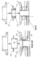
- Figures 4 and 5 show the insertion of the compensation assembly into the neck tube according to the prior art (left) and according to the present invention (right).
- the neck tube presents an external bulb-shaped portion 104 which is adjusted inside a spherical socket formed by connection of half-collar elements 102 and 103 which are secured via the third top junction element 100 and the annular portion 101.
- the assembly thus formed is yet lodged into the now visible external collar 105, provided with sliding parts for enabling radial displacement.
- the compensation assembly according to the present invention is provided by the connection of a less number of components, that is the collar element 61 disposed around the neck tube 5 providing radial displacement and the spherical socket formed by connection of top and bottom collar elements 621 and 622.
- the spherical socket provides also means for compensating axial displacement, as sliding part 7 is formed directly on the top collar portion 621.
- the innovative design can be assembled independent from the segment. It may be installed during the assembly of the gas turbine. It will also be appreciated that separating the assembly of the segment and the spherical joint improves the sourcing.
- the assembly according to the invention may be ordered at a different supplier and directly delivered to the gas turbine assembly site.
- the spherical joint of the assembly according to the invention may be manufactured by turning operation, whilst the assembly according to the prior art requires turning operations as well as EDM (Electric Discharge Machining).
- EDM Electro Discharge Machining
- EDM Electro Discharge Machining
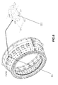
- Figure 6 shows the carrier structure 11 in a perspective view.
- an elongated opening 111 is advantageously provided in the carrier structure 11, where the neck tube is inserted (not shown).
- an insert element (not shown in the figure) is introduced and connected to the carrier structure 11 at the interface between the protruding neck tube (not shown) and the carrier structure 11, in correspondence of the elongated opening 111.
- FIG 7 shows a perspective view of the segment 9, having cooling channels 91 formed on its surface, on which the protruding neck tube 5 of the resonator cavity is attached.
- the cross section area of the cooling channels adjacent thereto reduces significantly. This leads to a reduction of cooling air flow, which results in an increased temperature of the component. It has been proven that it is not sufficient to increase the cross section area of the cooling channels by removing the ribs. There are not enough ribs to compensate for the neck blockage and also the ribs are necessarily required for the mechanical integrity of the segment.
- the insert element is introduced between the neck tube 5 and the elongated hole located on the carrier structure to address such technical problem.
- the insert element is shown in a perspective view in following figure 8 , and generally denoted with the numeral reference 12.
- the insert element 12 comprises a connecting portion 121 adapted to secure the insert element 12 to the carrier structure (not shown), a through hole 122 for admitting the neck tube and a base slopped portion 123.
- the base slopped portion 123 is such to increase the height of the cooling channel, in order to compensate for the blockage due to the presence of the neck tube, thus providing a wider channel for the cooling fluid.
- the insert is positioned in such a way that it facilitates the increase of the cooling channel height.
- the increase of the cooling channel height is aerodynamically formed to avoid unnecessary pressure losses therein.
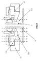
- Figure 9 shows the schematic sectional view of the neck tube 5 protruding from the segment 9 through the elongated opening 111, wherein the opening 111 is closed by the insert element 12, comprising the connecting portion 121 securing the insert 12 to the carrier structure 11 and the slopped portion 123.
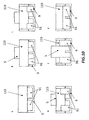
- subsequent section lines A-F are indicated, and correspondent frontal views of the segment 9 are depicted in figure 10 . It is in fact shown how, advancing along the cooling channels 91 of the segment 9, the slopped portion 123 provides a compensation for the reduction of the cooling channels 91 due to the presence of neck tube 5. In fact, in correspondence of sections C-F the slopped portion 123, decreasing the extent of its section, increases the height of the channels 91 providing such compensation.
Landscapes
- Engineering & Computer Science (AREA)
- Chemical & Material Sciences (AREA)
- Combustion & Propulsion (AREA)
- Mechanical Engineering (AREA)
- General Engineering & Computer Science (AREA)
- Turbine Rotor Nozzle Sealing (AREA)
- Vessels And Coating Films For Discharge Lamps (AREA)
Abstract
Description
- The present invention relates to dampers for gas turbine and, more in particular, to a compensation assembly for a damper of a gas turbine for reducing the pulsations occurring in the combustion chamber.
- In conventional gas turbines, acoustic oscillation usually occurs in the combustion chamber of the gas turbines during combustion process due to combustion instability and varieties. This acoustic oscillation may evolve into highly pronounced resonance. Such oscillation, which is also known as combustion chamber pulsations, can assume amplitudes and associated pressure fluctuations that subject the combustion chamber itself to severe mechanical loads that my decisively reduce the life of the combustion chamber and, in the worst case, may even lead to destruction of the combustion chamber.
Generally, a type of damper known as Helmholtz damper is utilized to damp the pulsations generated in the combustion chamber of the gas turbine. Currently, one of the main difficulties in utilization of such damper is the fact that the space available for these dampers is limited. One possible approach in addressing such situation is to place the damper on the outer side of the combustion chamber. In practice, the thermal expansion of the different layers composing the combustion chamber prevents directly applying such dampers.
A damping arrangement for reducing resonant vibrations in a combustion chamber of a gas turbine is disclosed inUS 2004/0248053 A1 , wherein the combustion chamber comprises an outer wall-surface part and an inner wall-surface part facing the combustion chamber, gas tightly encloses an intermediate space, into which cooling air can be fed for purposes of convective cooling of the combustion chamber wall. At least one third wall-surface part is provided, which, with the outer wall-surface part, encloses a gastight volume. The gastight volume is connected gas tightly to the combustion chamber by at least one connecting line. A gasket is welded at an end of the connecting line that is located in the gastight volume, and covers the outer wall surface part to provide gas tightness. With this gasket and connecting lines, the damping arrangement may compensate thermal expansion difference between the outer and inner wall-surface part in one direction.
A combustion chamber suitable for a gas turbine engine is provided inUS 2006/0123791 A1 , which comprise at least one Helmholtz resonator having a resonator cavity and a resonator neck in flow communication with the chamber interior. The Helmholtz resonator is fixed to an inner casing of the combustion chamber, with the resonator neck penetrating into the interior of the combustion chamber through an opening on the inner wall of the combustion chamber. An annular sealing member is provided around the outer periphery of the neck to provide gas tight seal between the neck and the opening. The neck provides limited relative axial movement of the neck with respect to the combustion chamber so that substantially no load is transferred from the resonator neck to the combustion chamber during engine operation.
A combustor for a gas turbine including at least one resonator is disclosed inWO 2012/057994 A2 , which comprises an outer liner and an inner liner. The resonator is coupled to the outer liner. The combustor liner includes a throat extending from the base of the resonator penetrating into the combustion chamber through the inner liner and the outer liner. The combustor liner further includes a grommet assembly that allows for relative thermal expansion between the inner liner and the outer liner proximate the throat in a first direction along the axis of the throat and a second direction perpendicular to the first direction.
A damper for gas turbine is also described inUS 2014/345285 which comprises a resonator cavity with an inlet and a neck tube in flow communication with the interior of the combustion chamber and resonator cavity, and a compensation assembly pivotably connected with the neck tube and inserted between the resonator cavity and the combustion chamber to permit relative rotation between the combustion chamber and the resonator cavity.
Even with above mentioned development in the pulsation damping field, there exists a large space to improve the compensation effect in eliminating thermal expansion difference. - It is an object of the present invention is to provide a compensation assembly associated to a damper for a gas turbine that may compensate relative rotation generated between the combustor chamber and the damper, in particular, the resonator cavity of the damper, due to thermal expansion difference.
This object is obtained by a compensation assembly for a damper of a combustion chamber of a gas turbine, the damper comprising a resonator cavity with a neck tube in flow communication with the interior of the combustion chamber, wherein the compensation assembly comprises a spherical joint associated to the neck tube and configured to allow relative rotation between the combustion chamber and the resonator cavity, and wherein the spherical joint comprises a bulb portion disposed around the neck tube and a spherical socket disposed around the neck tube and adapted to internally host the bulb portion, wherein the spherical socket is formed by a top collar portion and a bottom collar portion connected to each other. - According to a preferred aspect of the invention, the bulb portion is a collar element inserted on the neck tube. According to a further preferred aspect, the collar element is internally shaped such to allow a relative radial displacement of the neck tube.
- According to a further preferred aspect of the invention, the collar element defines internally a cylindrical surface.
- According to a further preferred aspect of the invention, the bottom and top collar portions are connected by a thread.
- According to a further preferred aspect of the invention, the compensation assembly further comprises a sliding part formed on the spherical socket adapted to be air-tightly fitted into a groove of the resonator cavity such to provide relative slide in a direction traversing a longitudinal axis of the neck tube between the sliding part and the groove.
- According to a further preferred aspect of the invention, the sliding part is formed on said top collar portion.
- It is a further object of the present invention to provide an insert element for a damper of a combustion chamber of a gas turbine, comprising a connecting portion adapted to secure the insert element to a carrier structure of the combustion chamber; a through hole for admitting a neck tube of the damper; and a base slopped portion.
- The objects, advantages and other features of the present invention will become more apparent upon reading of the following non-restrictive description of preferred embodiments thereof, given for the purpose of exemplification only, with reference to the accompany drawing, through which similar reference numerals may be used to refer to similar elements, and in which:
-
Fig. 1 shows a schematic sectional view of a compensation assembly according to the present invention; -
Fig. 2 shows a comparison of exploded views of a compensation assembly according to the prior art (left) and the compensation assembly according to the present invention (right); -
Fig. 3 shows a cross-sectional view of the compensation assembly according to the present invention; -
Fig. 4 and5 show a comparison between the mounting of the compensation assembly according to the prior art (left) and the mounting of the compensation assembly according to the present invention (right) on the neck tube; -
Fig. 6 shows an annular portion of a carrier structure of a combustion chamber; -
Fig. 7 shows a perspective view of a segment where a neck tube is mounted; -
Fig.8 shows a perspective view of an insert element according to the present invention; and -
Fig. 9 and10 show subsequent section/frontal views of the segment where the neck tube and the insert element are mounted. - With reference to
figure 1 , it is shown a schematic cross sectional view of a compensation assembly according the present invention, generally denoted withnumeral reference 1. Thecompensation assembly 1 is associated to a damper of acombustion chamber 3. The damper comprises aresonator cavity 4 with a box or cylinder shape as delimitated by aperipheral wall 13 and aninlet 14. As shown infigure 1 , the major part of theresonator cavity 4 is cut away as this would not prevent full and complete understanding of the technical solutions of the present invention. Also, only parts of thecombustion chamber 3 closely related to the present invention is shown infigure 1 for clarity and simplicity. Theresonator cavity 4 is air tightly attached to acarrier structure 11 of acombustion chamber 3 by fasteners, not shown infigure 1 . In an example implementation of the present invention, thecarrier structure 11 of thecombustion chamber 3 may be a casing of thecombustion chamber 3. Those skilled in the art should appreciate that thecarrier structure 11 provides a carrier for theresonator cavity 4, and should not be limited to the casing of the combustion chamber as described herein. In addition, the damper comprises aneck tube 5 that is in flow communication with theresonator cavity 4 through thecompensation assembly 1 according to the present invention in order to compensate relative movement between theresonator cavity 4 and thecombustion chamber 3.
Theneck tube 5 is air tightly attached at afirst end 91 thereof to awall portion 9, or segment, of thecombustion chamber 3. For example, afirst end 51 of theneck tube 4 may be welded to thesegment 9 of thecombustion chamber 3. Thecompensation assembly 1 comprises a spherical joint, generally denoted with 6, associated to theneck tube 5 and configured to allow a relative rotation between thecombustion chamber 3 and theresonator cavity 4. In particular, thespherical joint 6 comprises abulb portion 61 which is disposed around theneck tube 5 and aspherical socket 62 which, in turn, is internally adapted to host thebulb portion 61 such to permit relative rotation betweenresonator cavity 4 andcombustion chamber 3. More in particular,spherical socket 62 is formed by atop collar portion 621 and abottom collar portion 622 connected to each other.
According to a preferred embodiment of the invention, thebulb portion 61 is also acollar element 61 which is inserted on theneck tube 5 and comprises an external rounded portion which is movable within thespherical socket 62.
Advantageously, thecollar element 61 is internally shaped such to permit a relative radial displacement as indicated by arrow R in the drawing. Preferably, thecollar element 61 internally defines a cylindrical surface, where theneck tube 5 is accommodated and can slide radially to compensate in such direction possible radial thermal expansions. Furthermore, in order to provide theresonator cavity 4 with means adapted to compensate possible thermal axial expansions along a direction traversing a longitudinal axis of theneck tube 5, indicated in the figure by arrows A,compensation assembly 1 comprises asliding part 7 formed on thespherical socket 62 and adapted to be air-tightly fitted within agroove 8 of theresonator cavity 4. Preferably, slidingpart 7 is formed on thetop collar portion 621 of thespherical socket 62. - With reference to next
figure 2 , it is showed a comparison between exploded views of a compensation assembly according to the prior art (left) vs the compensation assembly according to the present invention (right).
The compensation assembly according to the prior art comprises two half-collar portions neck tube 104. A bulb portion is integrally formed on theneck tube 104, which is hosted into a correspondent internal spherical socket formed by the half-collar portions top junction element 100 and anannular portion 101. Differently and advantageously, the compensation assembly according to the invention involves a reduction of number of parts to be assembled as well as the avoidance of a bulb portion integrally formed on a portion of the external surface of theneck tube 104. In fact, thebulb portion 61 is now enclosed within the twocollar portions bottom collars bulb portion 61 is yet a collar element internally cylindrically shaped such to accommodate the neck tube (not pictured) and allow relative radial displacement. Differently, according to the prior art, theannular portion 101 is also hosted into a yet another external collar (not shown) to provide radial displacement. Such external collar comprises sliding parts. According to the invention, the slidingparts 7 are advantageously formed on thetop collar portion 621 of thespherical socket 62. - Making now reference to following
figure 3 , it is shown a cross sectional view of the compensation assembly according to the present invention. In particular, it is clearly shown the bulb portion of thecollar element 61 which is hosted into a correspondent spherical socket formed by the connection of the top andbottom collar portions -
Figures 4 and5 show the insertion of the compensation assembly into the neck tube according to the prior art (left) and according to the present invention (right). According to the known art, the neck tube presents an external bulb-shapedportion 104 which is adjusted inside a spherical socket formed by connection of half-collar elements top junction element 100 and theannular portion 101. To provide radial displacement, the assembly thus formed is yet lodged into the now visibleexternal collar 105, provided with sliding parts for enabling radial displacement. The compensation assembly according to the present invention, conversely, is provided by the connection of a less number of components, that is thecollar element 61 disposed around theneck tube 5 providing radial displacement and the spherical socket formed by connection of top andbottom collar elements part 7 is formed directly on thetop collar portion 621.
It will then be appreciated that the new compensation assembly, compared to the known art, facilitates the assembly procedure in the factory, improves the sourcing of the different parts as well as facilitating the machining of the different components. As the number of components is reduced, this advantageously affects the costs involved. Furthermore, the assembly according to the prior art needed to be assembled to the segment prior to the installation in the gas turbine. The innovative design can be assembled independent from the segment. It may be installed during the assembly of the gas turbine.
It will also be appreciated that separating the assembly of the segment and the spherical joint improves the sourcing. The assembly according to the invention may be ordered at a different supplier and directly delivered to the gas turbine assembly site. The spherical joint of the assembly according to the invention may be manufactured by turning operation, whilst the assembly according to the prior art requires turning operations as well as EDM (Electric Discharge Machining). In particular, EDM is generally used for thehalf collar elements -
Figure 6 shows thecarrier structure 11 in a perspective view. In order to enable the installation of the segment with the protruding neck into thecarrier structure 11 it is advisable to have a sufficient wide opening. For this reason, anelongated opening 111 is advantageously provided in thecarrier structure 11, where the neck tube is inserted (not shown). In order to close an open gap formed between the opening 111 in thecarrier 11 and the neck tube, an insert element (not shown in the figure) is introduced and connected to thecarrier structure 11 at the interface between the protruding neck tube (not shown) and thecarrier structure 11, in correspondence of theelongated opening 111. - Next
figure 7 shows a perspective view of thesegment 9, havingcooling channels 91 formed on its surface, on which the protrudingneck tube 5 of the resonator cavity is attached. As clearly visible in the figure, by implementing a neck tube into thesegment 9, the cross section area of the cooling channels adjacent thereto reduces significantly. This leads to a reduction of cooling air flow, which results in an increased temperature of the component. It has been proven that it is not sufficient to increase the cross section area of the cooling channels by removing the ribs. There are not enough ribs to compensate for the neck blockage and also the ribs are necessarily required for the mechanical integrity of the segment. Advantageously, the insert element is introduced between theneck tube 5 and the elongated hole located on the carrier structure to address such technical problem. - The insert element is shown in a perspective view in following
figure 8 , and generally denoted with thenumeral reference 12. In particular, theinsert element 12 comprises a connectingportion 121 adapted to secure theinsert element 12 to the carrier structure (not shown), a throughhole 122 for admitting the neck tube and a base sloppedportion 123. Advantageously, the base sloppedportion 123 is such to increase the height of the cooling channel, in order to compensate for the blockage due to the presence of the neck tube, thus providing a wider channel for the cooling fluid. More in particular, the insert is positioned in such a way that it facilitates the increase of the cooling channel height. The increase of the cooling channel height is aerodynamically formed to avoid unnecessary pressure losses therein. - This is better explained and illustrated with reference to last
figures 9 and10 , taken in combination.Figure 9 shows the schematic sectional view of theneck tube 5 protruding from thesegment 9 through theelongated opening 111, wherein theopening 111 is closed by theinsert element 12, comprising the connectingportion 121 securing theinsert 12 to thecarrier structure 11 and the sloppedportion 123. In the drawings subsequent section lines A-F are indicated, and correspondent frontal views of thesegment 9 are depicted infigure 10 . It is in fact shown how, advancing along the coolingchannels 91 of thesegment 9, the sloppedportion 123 provides a compensation for the reduction of thecooling channels 91 due to the presence ofneck tube 5. In fact, in correspondence of sections C-F the sloppedportion 123, decreasing the extent of its section, increases the height of thechannels 91 providing such compensation. - While the invention has been described in detail in connection with only a limited number of embodiments, it should be readily understood that the invention is not limited to such disclosed embodiments. Rather, the invention can be modified to incorporate any number of variations, alterations, substitutions or equivalent arrangements not heretofore described, but which are commensurate with the spirit and scope of the invention. Additionally, while various embodiments of the invention have been described, it is to be understood that aspects of the invention may include only some of the described embodiments. Accordingly, the invention is not to be seen as limited by the foregoing description, but is only limited by the scope of the appended claims.
Claims (8)
- A compensation assembly (1) for a damper of a combustion chamber (3) of a gas turbine, the damper comprising a resonator cavity (4) with a neck tube (5) in flow communication with the interior of the combustion chamber (3), the compensation assembly (1) comprising a spherical joint (6) associated to the neck tube (5) and configured to allow relative rotation between the combustion chamber (3) and the resonator cavity (4), the spherical joint (6) comprising:- a bulb portion (61) disposed around the neck tube (5);- a spherical socket (62) adapted to internally host said bulb portion (61), characterised in that the spherical socket (62) comprises a top collar portion (621) and a bottom collar portion (622), the top and bottom portions (621, 622) being connected to each other.
- The compensation assembly (1) according to the preceding claim, wherein said bulb portion (61) is a collar element (61) inserted on the neck tube (5).
- The compensation assembly (1) according to the preceding claim, wherein said collar element (61) is internally shaped such to allow a relative radial displacement of the neck tube (5).
- The compensation assembly (1) according to the preceding claim, wherein said collar element (61) defines internally a cylindrical surface.
- The compensation assembly (1) according to any of the preceding claims, wherein said bottom and top collar portions (621, 622) are connected by thread.
- The compensation assembly (1) according to any of the preceding claims, further comprising a sliding part (7) formed on the spherical socket (62) adapted to be air-tightly fitted into a groove (8) of the resonator cavity (4) such to provide relative slide in a direction traversing a longitudinal axis of the neck tube (5) between said sliding part (7) and the groove (8).
- The compensation assembly (1) according to the preceding claim, wherein said sliding part (7) is formed on said top collar portion (621).
- Insert element (12) for a damper of a combustion chamber (3) of a gas turbine, comprising:- a connecting portion (121) adapted to secure the insert element (12) to a carrier structure (11) of the combustion chamber (3);- a through hole (122) for admitting a neck tube (5) of the damper; and- a base slopped portion (123).
Priority Applications (5)
| Application Number | Priority Date | Filing Date | Title |
|---|---|---|---|
| EP14197299.2A EP3032177B1 (en) | 2014-12-11 | 2014-12-11 | Compensation assembly for a damper of a gas turbine |
| KR1020150173816A KR20160071327A (en) | 2014-12-11 | 2015-12-08 | Compensation assembly for a damper of a gas turbine |
| JP2015241066A JP2016121868A (en) | 2014-12-11 | 2015-12-10 | Compensation assembly for damper of gas turbine |
| US14/965,689 US10527284B2 (en) | 2014-12-11 | 2015-12-10 | Compensation assembly for a damper of a gas turbine |
| CN201510912291.6A CN105698217B (en) | 2014-12-11 | 2015-12-11 | Compensation assembly for a damper of a gas turbine |
Applications Claiming Priority (1)
| Application Number | Priority Date | Filing Date | Title |
|---|---|---|---|
| EP14197299.2A EP3032177B1 (en) | 2014-12-11 | 2014-12-11 | Compensation assembly for a damper of a gas turbine |
Publications (2)
| Publication Number | Publication Date |
|---|---|
| EP3032177A1 true EP3032177A1 (en) | 2016-06-15 |
| EP3032177B1 EP3032177B1 (en) | 2018-03-21 |
Family
ID=52103214
Family Applications (1)
| Application Number | Title | Priority Date | Filing Date |
|---|---|---|---|
| EP14197299.2A Active EP3032177B1 (en) | 2014-12-11 | 2014-12-11 | Compensation assembly for a damper of a gas turbine |
Country Status (5)
| Country | Link |
|---|---|
| US (1) | US10527284B2 (en) |
| EP (1) | EP3032177B1 (en) |
| JP (1) | JP2016121868A (en) |
| KR (1) | KR20160071327A (en) |
| CN (1) | CN105698217B (en) |
Cited By (3)
| Publication number | Priority date | Publication date | Assignee | Title |
|---|---|---|---|---|
| US11156164B2 (en) | 2019-05-21 | 2021-10-26 | General Electric Company | System and method for high frequency accoustic dampers with caps |
| US11174792B2 (en) | 2019-05-21 | 2021-11-16 | General Electric Company | System and method for high frequency acoustic dampers with baffles |
| US11506382B2 (en) | 2019-09-12 | 2022-11-22 | General Electric Company | System and method for acoustic dampers with multiple volumes in a combustion chamber front panel |
Families Citing this family (8)
| Publication number | Priority date | Publication date | Assignee | Title |
|---|---|---|---|---|
| US10228138B2 (en) | 2016-12-02 | 2019-03-12 | General Electric Company | System and apparatus for gas turbine combustor inner cap and resonating tubes |
| US10220474B2 (en) | 2016-12-02 | 2019-03-05 | General Electricd Company | Method and apparatus for gas turbine combustor inner cap and high frequency acoustic dampers |
| US10221769B2 (en) | 2016-12-02 | 2019-03-05 | General Electric Company | System and apparatus for gas turbine combustor inner cap and extended resonating tubes |
| FR3096115B1 (en) * | 2019-05-14 | 2022-12-09 | Safran Aircraft Engines | TURBOMACHINE COMBUSTION CHAMBER ATTACHMENT |
| CN115200046B (en) * | 2021-04-14 | 2023-09-26 | 中国航发商用航空发动机有限责任公司 | Full ring combustion chamber test device and its test method |
| CN117917528A (en) | 2022-10-20 | 2024-04-23 | 通用电气公司 | Fairing damper for combustor |
| CN117917527A (en) | 2022-10-20 | 2024-04-23 | 通用电气公司 | Burner parts |
| CN118856366B (en) * | 2024-08-09 | 2025-02-07 | 无锡明阳氢燃动力科技有限公司 | Combustion chamber for suppressing thermoacoustic oscillation and wavelength tube adjustment method for pure hydrogen gas turbine |
Citations (5)
| Publication number | Priority date | Publication date | Assignee | Title |
|---|---|---|---|---|
| US20040248053A1 (en) | 2001-09-07 | 2004-12-09 | Urs Benz | Damping arrangement for reducing combustion-chamber pulsation in a gas turbine system |
| US20060123791A1 (en) | 2004-12-11 | 2006-06-15 | Macquisten Michael A | Combustion chamber for a gas turbine engine |
| EP2397759A1 (en) * | 2010-06-16 | 2011-12-21 | Alstom Technology Ltd | Damper Arrangement |
| WO2012057994A2 (en) | 2010-10-29 | 2012-05-03 | Solar Turbines Incorporated | Gas turbine combustor with mounting for helmholtz resonators |
| US20140345285A1 (en) | 2013-05-24 | 2014-11-27 | Alstom Technology Ltd | Damper for gas turbines |
Family Cites Families (8)
| Publication number | Priority date | Publication date | Assignee | Title |
|---|---|---|---|---|
| US2273395A (en) * | 1941-01-31 | 1942-02-17 | Flex O Tube Company | Universal tubing fitting |
| US4454711A (en) * | 1981-10-29 | 1984-06-19 | Avco Corporation | Self-aligning fuel nozzle assembly |
| US5658022A (en) * | 1995-07-27 | 1997-08-19 | Shi; Wu-Huan | Pipe connector improvement structure |
| US7024863B2 (en) * | 2003-07-08 | 2006-04-11 | Pratt & Whitney Canada Corp. | Combustor attachment with rotational joint |
| JP2005076982A (en) * | 2003-08-29 | 2005-03-24 | Mitsubishi Heavy Ind Ltd | Gas turbine combustor |
| DE102011089295A1 (en) * | 2011-12-20 | 2013-06-20 | Robert Bosch Gmbh | Decoupling element for a fuel injection device |
| EP2642203A1 (en) * | 2012-03-20 | 2013-09-25 | Alstom Technology Ltd | Annular Helmholtz damper |
| US20140034528A1 (en) * | 2012-08-01 | 2014-02-06 | Dynamic Brands, Llc | Golf Bags, Golf Bag Top Members, and Golf Bag Top Member Coverings |
-
2014
- 2014-12-11 EP EP14197299.2A patent/EP3032177B1/en active Active
-
2015
- 2015-12-08 KR KR1020150173816A patent/KR20160071327A/en not_active Withdrawn
- 2015-12-10 JP JP2015241066A patent/JP2016121868A/en active Pending
- 2015-12-10 US US14/965,689 patent/US10527284B2/en active Active
- 2015-12-11 CN CN201510912291.6A patent/CN105698217B/en active Active
Patent Citations (5)
| Publication number | Priority date | Publication date | Assignee | Title |
|---|---|---|---|---|
| US20040248053A1 (en) | 2001-09-07 | 2004-12-09 | Urs Benz | Damping arrangement for reducing combustion-chamber pulsation in a gas turbine system |
| US20060123791A1 (en) | 2004-12-11 | 2006-06-15 | Macquisten Michael A | Combustion chamber for a gas turbine engine |
| EP2397759A1 (en) * | 2010-06-16 | 2011-12-21 | Alstom Technology Ltd | Damper Arrangement |
| WO2012057994A2 (en) | 2010-10-29 | 2012-05-03 | Solar Turbines Incorporated | Gas turbine combustor with mounting for helmholtz resonators |
| US20140345285A1 (en) | 2013-05-24 | 2014-11-27 | Alstom Technology Ltd | Damper for gas turbines |
Cited By (3)
| Publication number | Priority date | Publication date | Assignee | Title |
|---|---|---|---|---|
| US11156164B2 (en) | 2019-05-21 | 2021-10-26 | General Electric Company | System and method for high frequency accoustic dampers with caps |
| US11174792B2 (en) | 2019-05-21 | 2021-11-16 | General Electric Company | System and method for high frequency acoustic dampers with baffles |
| US11506382B2 (en) | 2019-09-12 | 2022-11-22 | General Electric Company | System and method for acoustic dampers with multiple volumes in a combustion chamber front panel |
Also Published As
| Publication number | Publication date |
|---|---|
| JP2016121868A (en) | 2016-07-07 |
| CN105698217B (en) | 2020-07-31 |
| US10527284B2 (en) | 2020-01-07 |
| US20160169513A1 (en) | 2016-06-16 |
| KR20160071327A (en) | 2016-06-21 |
| EP3032177B1 (en) | 2018-03-21 |
| CN105698217A (en) | 2016-06-22 |
Similar Documents
| Publication | Publication Date | Title |
|---|---|---|
| US10527284B2 (en) | Compensation assembly for a damper of a gas turbine | |
| EP2816288B1 (en) | Combustion chamber for a gas turbine with a vibration damper | |
| EP3194850B1 (en) | Acoustic damping system for a combustor of a gas turbine engine | |
| CN100472046C (en) | Connection between the cooling air chamber and the guide of a gas turbine engine | |
| US10386065B2 (en) | Concentric resonators for machines | |
| CN105781743B (en) | Damper for a gas turbine | |
| JP2019526028A (en) | Gas turbine engine with resonator ring | |
| CN101952556A (en) | Rotary mechanism scroll structure and rotary mechanism | |
| RU2666828C2 (en) | Heat-shield manifold system for midframe case of gas turbine engine | |
| US10309654B2 (en) | Structure for cooling gas turbine engine | |
| US8677765B2 (en) | Gas-turbine combustion chamber with a holding mechanism for a seal for an attachment | |
| US20160340053A1 (en) | Turbomachine comprising a ventilation system | |
| CN101096919A (en) | Turbine | |
| US9394830B2 (en) | Inverted cap igniter tube | |
| RU2380546C2 (en) | Gas turbine engine comprising two axially jointed assemblies | |
| US10066509B2 (en) | Turbomachine part comprising a flange with a drainage device | |
| US20200256254A1 (en) | Deflector, deflector assembly and turbine center frame | |
| EP3059395B1 (en) | Combustor aft mount assembly | |
| RU2574108C2 (en) | Combustion chamber (versions) and silencer for gas turbines | |
| CA2756371A1 (en) | Seal arrangement |
Legal Events
| Date | Code | Title | Description |
|---|---|---|---|
| PUAI | Public reference made under article 153(3) epc to a published international application that has entered the european phase |
Free format text: ORIGINAL CODE: 0009012 |
|
| AK | Designated contracting states |
Kind code of ref document: A1 Designated state(s): AL AT BE BG CH CY CZ DE DK EE ES FI FR GB GR HR HU IE IS IT LI LT LU LV MC MK MT NL NO PL PT RO RS SE SI SK SM TR |
|
| AX | Request for extension of the european patent |
Extension state: BA ME |
|
| RAP1 | Party data changed (applicant data changed or rights of an application transferred) |
Owner name: GENERAL ELECTRIC TECHNOLOGY GMBH |
|
| 17P | Request for examination filed |
Effective date: 20161215 |
|
| RBV | Designated contracting states (corrected) |
Designated state(s): AL AT BE BG CH CY CZ DE DK EE ES FI FR GB GR HR HU IE IS IT LI LT LU LV MC MK MT NL NO PL PT RO RS SE SI SK SM TR |
|
| RAP1 | Party data changed (applicant data changed or rights of an application transferred) |
Owner name: ANSALDO ENERGIA SWITZERLAND AG |
|
| GRAP | Despatch of communication of intention to grant a patent |
Free format text: ORIGINAL CODE: EPIDOSNIGR1 |
|
| INTG | Intention to grant announced |
Effective date: 20171004 |
|
| GRAS | Grant fee paid |
Free format text: ORIGINAL CODE: EPIDOSNIGR3 |
|
| GRAA | (expected) grant |
Free format text: ORIGINAL CODE: 0009210 |
|
| AK | Designated contracting states |
Kind code of ref document: B1 Designated state(s): AL AT BE BG CH CY CZ DE DK EE ES FI FR GB GR HR HU IE IS IT LI LT LU LV MC MK MT NL NO PL PT RO RS SE SI SK SM TR |
|
| REG | Reference to a national code |
Ref country code: GB Ref legal event code: FG4D |
|
| REG | Reference to a national code |
Ref country code: CH Ref legal event code: EP |
|
| REG | Reference to a national code |
Ref country code: AT Ref legal event code: REF Ref document number: 981516 Country of ref document: AT Kind code of ref document: T Effective date: 20180415 |
|
| REG | Reference to a national code |
Ref country code: IE Ref legal event code: FG4D |
|
| REG | Reference to a national code |
Ref country code: DE Ref legal event code: R096 Ref document number: 602014022554 Country of ref document: DE |
|
| REG | Reference to a national code |
Ref country code: NL Ref legal event code: MP Effective date: 20180321 |
|
| PG25 | Lapsed in a contracting state [announced via postgrant information from national office to epo] |
Ref country code: HR Free format text: LAPSE BECAUSE OF FAILURE TO SUBMIT A TRANSLATION OF THE DESCRIPTION OR TO PAY THE FEE WITHIN THE PRESCRIBED TIME-LIMIT Effective date: 20180321 Ref country code: NO Free format text: LAPSE BECAUSE OF FAILURE TO SUBMIT A TRANSLATION OF THE DESCRIPTION OR TO PAY THE FEE WITHIN THE PRESCRIBED TIME-LIMIT Effective date: 20180621 Ref country code: FI Free format text: LAPSE BECAUSE OF FAILURE TO SUBMIT A TRANSLATION OF THE DESCRIPTION OR TO PAY THE FEE WITHIN THE PRESCRIBED TIME-LIMIT Effective date: 20180321 Ref country code: LT Free format text: LAPSE BECAUSE OF FAILURE TO SUBMIT A TRANSLATION OF THE DESCRIPTION OR TO PAY THE FEE WITHIN THE PRESCRIBED TIME-LIMIT Effective date: 20180321 Ref country code: CY Free format text: LAPSE BECAUSE OF FAILURE TO SUBMIT A TRANSLATION OF THE DESCRIPTION OR TO PAY THE FEE WITHIN THE PRESCRIBED TIME-LIMIT Effective date: 20180321 |
|
| REG | Reference to a national code |
Ref country code: LT Ref legal event code: MG4D |
|
| REG | Reference to a national code |
Ref country code: AT Ref legal event code: MK05 Ref document number: 981516 Country of ref document: AT Kind code of ref document: T Effective date: 20180321 |
|
| PG25 | Lapsed in a contracting state [announced via postgrant information from national office to epo] |
Ref country code: RS Free format text: LAPSE BECAUSE OF FAILURE TO SUBMIT A TRANSLATION OF THE DESCRIPTION OR TO PAY THE FEE WITHIN THE PRESCRIBED TIME-LIMIT Effective date: 20180321 Ref country code: LV Free format text: LAPSE BECAUSE OF FAILURE TO SUBMIT A TRANSLATION OF THE DESCRIPTION OR TO PAY THE FEE WITHIN THE PRESCRIBED TIME-LIMIT Effective date: 20180321 Ref country code: SE Free format text: LAPSE BECAUSE OF FAILURE TO SUBMIT A TRANSLATION OF THE DESCRIPTION OR TO PAY THE FEE WITHIN THE PRESCRIBED TIME-LIMIT Effective date: 20180321 Ref country code: GR Free format text: LAPSE BECAUSE OF FAILURE TO SUBMIT A TRANSLATION OF THE DESCRIPTION OR TO PAY THE FEE WITHIN THE PRESCRIBED TIME-LIMIT Effective date: 20180622 Ref country code: BG Free format text: LAPSE BECAUSE OF FAILURE TO SUBMIT A TRANSLATION OF THE DESCRIPTION OR TO PAY THE FEE WITHIN THE PRESCRIBED TIME-LIMIT Effective date: 20180621 |
|
| PG25 | Lapsed in a contracting state [announced via postgrant information from national office to epo] |
Ref country code: RO Free format text: LAPSE BECAUSE OF FAILURE TO SUBMIT A TRANSLATION OF THE DESCRIPTION OR TO PAY THE FEE WITHIN THE PRESCRIBED TIME-LIMIT Effective date: 20180321 Ref country code: AL Free format text: LAPSE BECAUSE OF FAILURE TO SUBMIT A TRANSLATION OF THE DESCRIPTION OR TO PAY THE FEE WITHIN THE PRESCRIBED TIME-LIMIT Effective date: 20180321 Ref country code: EE Free format text: LAPSE BECAUSE OF FAILURE TO SUBMIT A TRANSLATION OF THE DESCRIPTION OR TO PAY THE FEE WITHIN THE PRESCRIBED TIME-LIMIT Effective date: 20180321 Ref country code: NL Free format text: LAPSE BECAUSE OF FAILURE TO SUBMIT A TRANSLATION OF THE DESCRIPTION OR TO PAY THE FEE WITHIN THE PRESCRIBED TIME-LIMIT Effective date: 20180321 Ref country code: ES Free format text: LAPSE BECAUSE OF FAILURE TO SUBMIT A TRANSLATION OF THE DESCRIPTION OR TO PAY THE FEE WITHIN THE PRESCRIBED TIME-LIMIT Effective date: 20180321 Ref country code: PL Free format text: LAPSE BECAUSE OF FAILURE TO SUBMIT A TRANSLATION OF THE DESCRIPTION OR TO PAY THE FEE WITHIN THE PRESCRIBED TIME-LIMIT Effective date: 20180321 |
|
| PG25 | Lapsed in a contracting state [announced via postgrant information from national office to epo] |
Ref country code: SK Free format text: LAPSE BECAUSE OF FAILURE TO SUBMIT A TRANSLATION OF THE DESCRIPTION OR TO PAY THE FEE WITHIN THE PRESCRIBED TIME-LIMIT Effective date: 20180321 Ref country code: CZ Free format text: LAPSE BECAUSE OF FAILURE TO SUBMIT A TRANSLATION OF THE DESCRIPTION OR TO PAY THE FEE WITHIN THE PRESCRIBED TIME-LIMIT Effective date: 20180321 Ref country code: AT Free format text: LAPSE BECAUSE OF FAILURE TO SUBMIT A TRANSLATION OF THE DESCRIPTION OR TO PAY THE FEE WITHIN THE PRESCRIBED TIME-LIMIT Effective date: 20180321 Ref country code: SM Free format text: LAPSE BECAUSE OF FAILURE TO SUBMIT A TRANSLATION OF THE DESCRIPTION OR TO PAY THE FEE WITHIN THE PRESCRIBED TIME-LIMIT Effective date: 20180321 |
|
| PG25 | Lapsed in a contracting state [announced via postgrant information from national office to epo] |
Ref country code: PT Free format text: LAPSE BECAUSE OF FAILURE TO SUBMIT A TRANSLATION OF THE DESCRIPTION OR TO PAY THE FEE WITHIN THE PRESCRIBED TIME-LIMIT Effective date: 20180723 |
|
| REG | Reference to a national code |
Ref country code: DE Ref legal event code: R097 Ref document number: 602014022554 Country of ref document: DE |
|
| PLBE | No opposition filed within time limit |
Free format text: ORIGINAL CODE: 0009261 |
|
| STAA | Information on the status of an ep patent application or granted ep patent |
Free format text: STATUS: NO OPPOSITION FILED WITHIN TIME LIMIT |
|
| PG25 | Lapsed in a contracting state [announced via postgrant information from national office to epo] |
Ref country code: DK Free format text: LAPSE BECAUSE OF FAILURE TO SUBMIT A TRANSLATION OF THE DESCRIPTION OR TO PAY THE FEE WITHIN THE PRESCRIBED TIME-LIMIT Effective date: 20180321 |
|
| 26N | No opposition filed |
Effective date: 20190102 |
|
| PG25 | Lapsed in a contracting state [announced via postgrant information from national office to epo] |
Ref country code: SI Free format text: LAPSE BECAUSE OF FAILURE TO SUBMIT A TRANSLATION OF THE DESCRIPTION OR TO PAY THE FEE WITHIN THE PRESCRIBED TIME-LIMIT Effective date: 20180321 |
|
| REG | Reference to a national code |
Ref country code: CH Ref legal event code: PL |
|
| GBPC | Gb: european patent ceased through non-payment of renewal fee |
Effective date: 20181211 |
|
| PG25 | Lapsed in a contracting state [announced via postgrant information from national office to epo] |
Ref country code: MC Free format text: LAPSE BECAUSE OF FAILURE TO SUBMIT A TRANSLATION OF THE DESCRIPTION OR TO PAY THE FEE WITHIN THE PRESCRIBED TIME-LIMIT Effective date: 20180321 Ref country code: LU Free format text: LAPSE BECAUSE OF NON-PAYMENT OF DUE FEES Effective date: 20181211 |
|
| REG | Reference to a national code |
Ref country code: IE Ref legal event code: MM4A |
|
| REG | Reference to a national code |
Ref country code: BE Ref legal event code: MM Effective date: 20181231 |
|
| PG25 | Lapsed in a contracting state [announced via postgrant information from national office to epo] |
Ref country code: IE Free format text: LAPSE BECAUSE OF NON-PAYMENT OF DUE FEES Effective date: 20181211 Ref country code: FR Free format text: LAPSE BECAUSE OF NON-PAYMENT OF DUE FEES Effective date: 20181231 |
|
| PG25 | Lapsed in a contracting state [announced via postgrant information from national office to epo] |
Ref country code: BE Free format text: LAPSE BECAUSE OF NON-PAYMENT OF DUE FEES Effective date: 20181231 |
|
| PG25 | Lapsed in a contracting state [announced via postgrant information from national office to epo] |
Ref country code: CH Free format text: LAPSE BECAUSE OF NON-PAYMENT OF DUE FEES Effective date: 20181231 Ref country code: GB Free format text: LAPSE BECAUSE OF NON-PAYMENT OF DUE FEES Effective date: 20181211 Ref country code: LI Free format text: LAPSE BECAUSE OF NON-PAYMENT OF DUE FEES Effective date: 20181231 |
|
| PG25 | Lapsed in a contracting state [announced via postgrant information from national office to epo] |
Ref country code: MT Free format text: LAPSE BECAUSE OF NON-PAYMENT OF DUE FEES Effective date: 20181211 |
|
| PG25 | Lapsed in a contracting state [announced via postgrant information from national office to epo] |
Ref country code: TR Free format text: LAPSE BECAUSE OF FAILURE TO SUBMIT A TRANSLATION OF THE DESCRIPTION OR TO PAY THE FEE WITHIN THE PRESCRIBED TIME-LIMIT Effective date: 20180321 |
|
| PG25 | Lapsed in a contracting state [announced via postgrant information from national office to epo] |
Ref country code: HU Free format text: LAPSE BECAUSE OF FAILURE TO SUBMIT A TRANSLATION OF THE DESCRIPTION OR TO PAY THE FEE WITHIN THE PRESCRIBED TIME-LIMIT; INVALID AB INITIO Effective date: 20141211 Ref country code: MK Free format text: LAPSE BECAUSE OF NON-PAYMENT OF DUE FEES Effective date: 20180321 |
|
| PG25 | Lapsed in a contracting state [announced via postgrant information from national office to epo] |
Ref country code: IS Free format text: LAPSE BECAUSE OF FAILURE TO SUBMIT A TRANSLATION OF THE DESCRIPTION OR TO PAY THE FEE WITHIN THE PRESCRIBED TIME-LIMIT Effective date: 20180721 |
|
| P01 | Opt-out of the competence of the unified patent court (upc) registered |
Effective date: 20240430 |
|
| PGFP | Annual fee paid to national office [announced via postgrant information from national office to epo] |
Ref country code: DE Payment date: 20251222 Year of fee payment: 12 |
|
| PGFP | Annual fee paid to national office [announced via postgrant information from national office to epo] |
Ref country code: IT Payment date: 20251231 Year of fee payment: 12 |