EP3032166A1 - Ventilation member - Google Patents
Ventilation member Download PDFInfo
- Publication number
- EP3032166A1 EP3032166A1 EP14835423.6A EP14835423A EP3032166A1 EP 3032166 A1 EP3032166 A1 EP 3032166A1 EP 14835423 A EP14835423 A EP 14835423A EP 3032166 A1 EP3032166 A1 EP 3032166A1
- Authority
- EP
- European Patent Office
- Prior art keywords
- ventilation member
- wall portion
- recessed
- member according
- portions
- Prior art date
- Legal status (The legal status is an assumption and is not a legal conclusion. Google has not performed a legal analysis and makes no representation as to the accuracy of the status listed.)
- Withdrawn
Links
Images




Classifications
-
- B—PERFORMING OPERATIONS; TRANSPORTING
- B01—PHYSICAL OR CHEMICAL PROCESSES OR APPARATUS IN GENERAL
- B01D—SEPARATION
- B01D39/00—Filtering material for liquid or gaseous fluids
- B01D39/14—Other self-supporting filtering material ; Other filtering material
- B01D39/16—Other self-supporting filtering material ; Other filtering material of organic material, e.g. synthetic fibres
- B01D39/1638—Other self-supporting filtering material ; Other filtering material of organic material, e.g. synthetic fibres the material being particulate
- B01D39/1653—Other self-supporting filtering material ; Other filtering material of organic material, e.g. synthetic fibres the material being particulate of synthetic origin
- B01D39/1661—Other self-supporting filtering material ; Other filtering material of organic material, e.g. synthetic fibres the material being particulate of synthetic origin sintered or bonded
-
- B—PERFORMING OPERATIONS; TRANSPORTING
- B01—PHYSICAL OR CHEMICAL PROCESSES OR APPARATUS IN GENERAL
- B01D—SEPARATION
- B01D46/00—Filters or filtering processes specially modified for separating dispersed particles from gases or vapours
- B01D46/10—Particle separators, e.g. dust precipitators, using filter plates, sheets or pads having plane surfaces
-
- B—PERFORMING OPERATIONS; TRANSPORTING
- B01—PHYSICAL OR CHEMICAL PROCESSES OR APPARATUS IN GENERAL
- B01D—SEPARATION
- B01D46/00—Filters or filtering processes specially modified for separating dispersed particles from gases or vapours
- B01D46/24—Particle separators, e.g. dust precipitators, using rigid hollow filter bodies
- B01D46/2403—Particle separators, e.g. dust precipitators, using rigid hollow filter bodies characterised by the physical shape or structure of the filtering element
-
- B—PERFORMING OPERATIONS; TRANSPORTING
- B01—PHYSICAL OR CHEMICAL PROCESSES OR APPARATUS IN GENERAL
- B01D—SEPARATION
- B01D46/00—Filters or filtering processes specially modified for separating dispersed particles from gases or vapours
- B01D46/52—Particle separators, e.g. dust precipitators, using filters embodying folded corrugated or wound sheet material
- B01D46/521—Particle separators, e.g. dust precipitators, using filters embodying folded corrugated or wound sheet material using folded, pleated material
-
- F—MECHANICAL ENGINEERING; LIGHTING; HEATING; WEAPONS; BLASTING
- F21—LIGHTING
- F21S—NON-PORTABLE LIGHTING DEVICES; SYSTEMS THEREOF; VEHICLE LIGHTING DEVICES SPECIALLY ADAPTED FOR VEHICLE EXTERIORS
- F21S45/00—Arrangements within vehicle lighting devices specially adapted for vehicle exteriors, for purposes other than emission or distribution of light
- F21S45/30—Ventilation or drainage of lighting devices
-
- H—ELECTRICITY
- H05—ELECTRIC TECHNIQUES NOT OTHERWISE PROVIDED FOR
- H05K—PRINTED CIRCUITS; CASINGS OR CONSTRUCTIONAL DETAILS OF ELECTRIC APPARATUS; MANUFACTURE OF ASSEMBLAGES OF ELECTRICAL COMPONENTS
- H05K5/00—Casings, cabinets or drawers for electric apparatus
- H05K5/02—Details
- H05K5/0213—Venting apertures; Constructional details thereof
- H05K5/0215—Venting apertures; Constructional details thereof with semi-permeable membranes attached to casings
-
- B—PERFORMING OPERATIONS; TRANSPORTING
- B01—PHYSICAL OR CHEMICAL PROCESSES OR APPARATUS IN GENERAL
- B01D—SEPARATION
- B01D2279/00—Filters adapted for separating dispersed particles from gases or vapours specially modified for specific uses
- B01D2279/35—Filters adapted for separating dispersed particles from gases or vapours specially modified for specific uses for venting arrangements
-
- B—PERFORMING OPERATIONS; TRANSPORTING
- B01—PHYSICAL OR CHEMICAL PROCESSES OR APPARATUS IN GENERAL
- B01D—SEPARATION
- B01D2279/00—Filters adapted for separating dispersed particles from gases or vapours specially modified for specific uses
- B01D2279/45—Filters adapted for separating dispersed particles from gases or vapours specially modified for specific uses for electronic devices, e.g. computers, hard-discs, mobile phones
Definitions
- the present invention relates to a ventilation member used to reduce pressure variation in a housing or to allow replacement of air in the housing.
- a housing containing an electric component or a control board is provided with an opening for the purpose of reducing pressure variation in the housing caused by temperature change or allowing replacement of air in the housing, and a ventilation member is attached to the opening.
- the ventilation member ensures ventilation between the inside and outside of the housing, and also prevents foreign matters such as dust and water from entering the housing.
- An example of such a ventilation member is disclosed in Patent Literature 1.
- Patent Literature 1 discloses a ventilation member 101 as shown in FIG. 10 to FIG. 12 .
- the ventilation member 101 includes a gas-permeable membrane 102 and a support body 103.
- the support body 103 has a through hole 103c, a first angled protruding portion 103a, and a second angled protruding portion 103b.
- the first and second angled protruding portions 103a and 103b are provided along two opposite edges of the opening of the through hole 103c and have alternate peaks and valleys.
- a gas-permeable membrane 102 is joined onto the first angled protruding portion 103a and the second angled protruding portion 103b and has a pleated shape with alternate peaks and valleys along the shape of the first angled protruding portion 103a and the second angled protruding portion 103b.
- a gas passes through the gas-permeable membrane 102, as a result of which ventilation between a space inside a housing and a space outside the housing can be ensured.
- Patent Literature 1 discloses a porous polytetrafluoroethylene (PTFE) membrane as the gas-permeable membrane 102.
- the porous structure of the porous PTFE membrane is formed by stretching and then the resulting porous PTFE membrane is subjected to pleating.
- the gas-permeable membrane 102 having a pleated shape as shown in the figures is obtained.
- the attachment portion 2b is usually fixed to the outer surface of the housing 50 with a fastener such as an adhesive tape or an adhesive agent.
- the attachment portion 2b may be fixed directly to the outer surface of the housing 50 by welding or the like.
- the opening portion 50a of the housing 50 has a rectangular shape
- the opening 2c also has the same rectangular shape as the opening portion 50a so that the opening portion 50a and the opening 2c are aligned with each other.
- the opening 2c is located at a position where the opening 2c and the opening portion 50a of the housing 50 communicate with each other.
- the attachment portion 2b is also formed of a porous resin like the wall portion 2a, the attachment portion 2b itself can serve as a gas passage. However, since the inner surface of the attachment portion 2b is fixed to the wall portion of the gas-impermeable housing 50, the gas permeability of the ventilation member 1A is substantially ensured by the wall portion 2a.
- Examples of the method for forming a coating film containing a polymer having a perfluoroalkyl group include: coating methods in which coating with a solution or a dispersion of a polymer having a perfluoroalkyl group is performed by air spraying, electrostatic spraying, dip coating, spin coating, roll coating (including kiss coating and gravure coating), curtain flow coating, impregnation, or the like; and coating film forming methods using electrodeposition coating or plasma polymerization.
- the thickness D1 of the ventilation member 1A (i.e., the thickness of the wall portion 2a) is desirably 0.2 mm or more and 20 mm or less, preferably 0.3 mm or more and 10 mm or less, more preferably 0.5 mm or more and 10 mm or less, even more preferably 1 mm or more and 5 mm or less, and particularly preferably 1.5 mm or more and 5 mm or less.
- the attachment portion 2b may have the same thickness as the wall portion 2a, or the attachment portion 2b may be designed to have a thickness slightly greater than the wall portion 2b.
- the height H1 of the ventilation member 1A (i.e., the height from the outer surface of the housing 50) is desirably 5 mm or more and 50 mm or less, and preferably 10 mm or more-and 30 mm or less.
- the ventilation member 1B includes a wall portion 3a, an attachment portion 3b, and a plurality of (specifically, four) recessed portions 3d.
- the wall portion 3a is formed to define the recessed portions 3d and allows a gas to pass through between its inner surface facing the recessed portions 3d and its outer surface opposite to the inner surface. These recessed portions 3d have one common opening 3c and are recessed from the opening 3c in the same direction.
- the attachment portion 3b is formed to extend outwardly around the rectangular opening 3c and provides an attachment surface adapted to be attached to a housing 50 that needs to be ventilated.
- the ventilation member 1B is formed of a porous resin, and at least the wall portion 3a and the attachment portion 3b are integrally formed.
- the wall portion 3a and the attachment portion 3b are not members that are separately formed and joined together but they are each a part of the ventilation member 1B as a single member formed of a porous resin.
- the wall portion 3a has bottom wall portions 3e defining the bottom surfaces of the respective recessed portions 3d and side wall portions 3f defining the peripheral surfaces of the respective recessed portions 3d.
- the wall portion 3a includes four separate projecting portions, and the projecting portions each have the bottom wall portion 3e and the side wall portion 3f.
- the four projecting portions are connected by connecting portions 3g.
- the outer surfaces of the connecting portions 3g facing outside the housing 50 are smoothly connected to the surface of the attachment portion 3b.
- the shape and number of the bottom wall portions 3e and those of the side wall portions 3f are not particularly limited.
- the outline of the bottom wall portion 3e need not be rectangular but may be circular so that the side wall portion 3f has a cylindrical shape.
- the bottom wall portions 3e, the side wall portions 3f, and the connecting portions 3g are integrally formed of a porous resin and constitute the wall portion 3a.
- Each of the bottom wall portions 3e, the side wall portions 3f, and the connecting portions 3g allows a gas to pass through between its inner surface and its outer surface opposite to the inner surface.
- the attachment portion 3b is the same as the attachment portion 2b, the description thereof is omitted.
- the opening 3c is divided into two or more openings (for example, each recessed portion 3d has an opening 3c) in an embodiment different from that shown in the figures, the attachment portion 3b is formed around a region including all the recessed portions 3d.
- the porous resin forming the ventilation member 1B is a porous molded body composed of resin fine particles that are bound together.
- the resin is not particularly limited, and it is preferably ultra-high molecular weight polyethylene.
- the surface of the ventilation member 1B may be subjected to liquid-repellent treatment.
- the preferred range of the thickness D2 of the ventilation member 1B (i.e., the thickness of the bottom wall portions 3e) is the same as that of the thickness D1, and the preferred range of the height H2 of the ventilation member 1B is the same as that of the height H1.
- the ventilation member 1C includes a wall portion 4a, an attachment portion 4b, and a recessed portion 4d having an opening 4c.
- the wall portion 4a is formed to define the recessed portion 4d and allows a gas to pass through between its inner surface facing the recessed portion 4d and its outer surface opposite to the inner surface.
- the attachment portion 4b is formed to extend outwardly around the opening 4c and provides an attachment surface adapted to be attached to a housing 50 that needs to be ventilated.
- the ventilation member 1C has one recessed portion 4d.
- the ventilation member 1C may have a plurality of recessed portions (i.e., a plurality of projecting portions as seen from the underside), and the attachment portion 4b may be formed around a region including these recessed portions.
- the ventilation member 1C is formed of a porous resin, and at least the wall portion 4a and the attachment portion 4b are integrally formed.
- attachment portion 4b is the same as the attachment portion 2b, the description thereof is omitted.
- the porous resin forming the ventilation member 1C is a porous molded body composed of resin fine particles that are bound together.
- the resin is not particularly limited, and it is preferably ultra-high molecular weight polyethylene.
- the surface of the ventilation member 1C may be subjected to liquid-repellent treatment.
Landscapes
- Chemical & Material Sciences (AREA)
- Chemical Kinetics & Catalysis (AREA)
- Engineering & Computer Science (AREA)
- Microelectronics & Electronic Packaging (AREA)
- Physics & Mathematics (AREA)
- Geometry (AREA)
- General Engineering & Computer Science (AREA)
- Casings For Electric Apparatus (AREA)
- Arrangement Of Elements, Cooling, Sealing, Or The Like Of Lighting Devices (AREA)
- Non-Portable Lighting Devices Or Systems Thereof (AREA)
- Filtering Materials (AREA)
Abstract
Description
- The present invention relates to a ventilation member used to reduce pressure variation in a housing or to allow replacement of air in the housing.
- Conventionally, for example, in automobile electric components such as automobile lamps and ECUs (Electrical Control Units), OA (office automation) equipment, household electric appliances, and medical devices, a housing containing an electric component or a control board is provided with an opening for the purpose of reducing pressure variation in the housing caused by temperature change or allowing replacement of air in the housing, and a ventilation member is attached to the opening. The ventilation member ensures ventilation between the inside and outside of the housing, and also prevents foreign matters such as dust and water from entering the housing. An example of such a ventilation member is disclosed in
Patent Literature 1. -
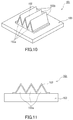
Patent Literature 1 discloses aventilation member 101 as shown inFIG. 10 to FIG. 12 . Theventilation member 101 includes a gas-permeable membrane 102 and asupport body 103. Thesupport body 103 has a throughhole 103c, a first angled protrudingportion 103a, and a second angled protrudingportion 103b. The first and second angled protrudingportions hole 103c and have alternate peaks and valleys. A gas-permeable membrane 102 is joined onto the first angled protrudingportion 103a and the second angled protrudingportion 103b and has a pleated shape with alternate peaks and valleys along the shape of the firstangled protruding portion 103a and the secondangled protruding portion 103b. In thisventilation member 101, a gas passes through the gas-permeable membrane 102, as a result of which ventilation between a space inside a housing and a space outside the housing can be ensured.Patent Literature 1 discloses a porous polytetrafluoroethylene (PTFE) membrane as the gas-permeable membrane 102. The porous structure of the porous PTFE membrane is formed by stretching and then the resulting porous PTFE membrane is subjected to pleating. Thus, the gas-permeable membrane 102 having a pleated shape as shown in the figures is obtained. - Patent Literature 1:
JP 2011-233518 A - The
ventilation member 101 disclosed inPatent Literature 1 is designed to increase the gas-permeable area by pleating the gas-permeable membrane 102. However, the firstangled protruding portion 103a and the second angled protrudingportion 103b formed in the gas-impermeable support body 103 do not contribute to improving the gas permeability. In addition, in order to prevent leakage of a gas through the joining portion of the gas-permeable membrane 102 and the first and second angled protrudingportions permeable membrane 102 and the first and second angled protrudingportions ventilation member 101 is not necessarily designed suitably for mass production. - In view of such circumstances, the present invention aims to provide a ventilation member suitable for improvement of gas permeability and mass production.
- The present invention provides a ventilation member formed of a porous resin. The ventilation member includes:
- at least one recessed portion having an opening;
- a wall portion formed to define the recessed portion and having an inner surface facing the recessed portion and an outer surface opposite to the inner surface, the wall portion being configured to allow a gas to pass through between the inner surface and the outer surface; and
- an attachment portion formed integrally with the wall portion to extend outwardly around the opening of the recessed portion and adapted to be attached to a housing that needs to be ventilated.
- According to the ventilation member of the present invention, the entire wall portion formed to define the recessed portion ensures gas permeability. In addition, the attachment portion for attachment to the housing is formed integrally with the wall portion. Therefore, the ventilation member is suitable for improvement of gas permeability and mass production.
-
-
FIG. 1 is a perspective view of a ventilation member according to a first embodiment of the present invention. -
FIG. 2 is a cross-sectional view of the ventilation member shown inFIG. 1 . -
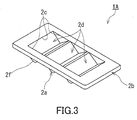
FIG. 3 is a perspective underside view of the ventilation member shown inFIG. 1 . -
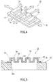
FIG. 4 is a perspective view of a ventilation member according to a second embodiment of the present invention. -
FIG. 5 is a cross-sectional view of the ventilation member shown inFIG. 4 . -
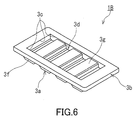
FIG. 6 is a perspective underside view of the ventilation member shown inFIG. 4 . -
FIG. 7 is a perspective view of a ventilation member according to a third embodiment of the present invention. -
FIG. 8 is a cross-sectional view of the ventilation member shown inFIG. 7 . -
FIG. 9 is a perspective underside view of the ventilation member shown inFIG. 7 . -
FIG. 10 is a perspective view of a conventional ventilation member. -
FIG. 11 is a side view of the ventilation member shown inFIG. 10 . -
FIG. 12 is a cross-sectional view of the ventilation member shown inFIG. 10 . - Hereinafter, embodiments of the present invention will be described with reference to the accompanying drawings. The following description relates to illustrative examples of the present invention, and these examples are not intended to limit the present invention. Hereinafter, the same components as those described previously are designated by the same reference numerals, and the description thereof is omitted in some cases.
-
FIG. 1 to FIG. 3 each show aventilation member 1A according to the first embodiment of the present invention. Theventilation member 1A includes awall portion 2a, anattachment portion 2b, and a plurality of (specifically, three) recessedportions 2d. Theserecessed portions 2d have onecommon opening 2c and are recessed from the opening 2c in the same direction. Thewall portion 2a is formed to define therecessed portions 2d and allows a gas to pass through between its inner surface facing therecessed portions 2d and its outer surface opposite to the inner surface. Theattachment portion 2b is formed to extend outwardly around therectangular opening 2c and provides an attachment surface adapted to be attached to ahousing 50 that needs to be ventilated. Theventilation member 1A is formed of a porous resin, and at least thewall portion 2a and theattachment portion 2b are integrally formed. Thewall portion 2a and theattachment portion 2b are not members that are separately formed and joined together but they are each a part of theventilation member 1A as a single member formed of a porous resin. - The
wall portion 2a has aninclined portion 2e having a ridged cross section andridged portions 2f closing both sides of theinclined portion 2e. In the present embodiment, theinclined portion 2e has a pleated shape with flattened ridges and includes three projecting portions. Theridged portions 2f cover both sides of the respective projecting portions and thus include six projection sides. The shape (for example, the inclination angle of the inclined surface of the projecting portion or that of the inclined side of the projection side) of theinclined portion 2e and theridged portion 2f and the number of theinclined portions 2e and theridged portions 2f are not particularly limited. Theinclined portion 2e and theridged portions 2f are integrally formed of a porous resin and constitute thewall portion 2a. - The
attachment portion 2b is usually fixed to the outer surface of thehousing 50 with a fastener such as an adhesive tape or an adhesive agent. Theattachment portion 2b may be fixed directly to the outer surface of thehousing 50 by welding or the like. In the present embodiment, theopening portion 50a of thehousing 50 has a rectangular shape, and the opening 2c also has the same rectangular shape as theopening portion 50a so that theopening portion 50a and the opening 2c are aligned with each other. The opening 2c is located at a position where the opening 2c and theopening portion 50a of thehousing 50 communicate with each other. Since theattachment portion 2b is also formed of a porous resin like thewall portion 2a, theattachment portion 2b itself can serve as a gas passage. However, since the inner surface of theattachment portion 2b is fixed to the wall portion of the gas-impermeable housing 50, the gas permeability of theventilation member 1A is substantially ensured by thewall portion 2a. - The porous resin forming the
ventilation member 1A is a porous molded body composed of resin fine particles that are bound together. Preferably, the porous resin molded body has a porosity of 20 to 90%. The resin is not particularly limited, and it is preferably ultra-high molecular weight polyethylene. As used herein, the term "ultra-high molecular weight polyethylene" refers to a polyethylene having an average molecular weight of 500,000 or more. The average molecular weight of ultra-high molecular weight polyethylene is generally in the range of 2,000,000 to 10,000,000. The average molecular weight can be measured, for example, by a method according to ASTM D 4020 (viscosity test). Hereinafter, ultra-high molecular weight polyethylene is abbreviated to "UHMWPE". - The porous UHMWPE resin molded body can be produced from a sintered body of UHMWPE powder. The sintered body of UHMWPE powder can be obtained by sintering UHMWPE powder (for example, an UHMWPE powder with an average particle diameter of 30 to 200 µm) placed in a mold at a temperature close to the melting point of UHMWPE (for example, a temperature of 130 to 160°C). The
ventilation member 1A formed of the porous UHMWPE resin molded body is obtained by using a mold of a desired shape for a sintered body or by cutting a sintered body block thus obtained into a desired shape. According to this production method (powder sintering method), the resulting porous UHMWPE resin molded body has a porosity in the range of 20 to 90%. - The surface of the
ventilation member 1A may be subjected to liquid-repellent treatment. The liquid-repellent treatment can be carried out by a commonly-known method. The liquid-repellent agent used for the liquid-repellent treatment is not particularly limited, and it is typically a material containing a polymer having a perfluoroalkyl group. Examples of the method for forming a coating film containing a polymer having a perfluoroalkyl group include: coating methods in which coating with a solution or a dispersion of a polymer having a perfluoroalkyl group is performed by air spraying, electrostatic spraying, dip coating, spin coating, roll coating (including kiss coating and gravure coating), curtain flow coating, impregnation, or the like; and coating film forming methods using electrodeposition coating or plasma polymerization. In the present embodiment, for example, in impregnation, a liquid-repellent agent that comprises a polymer containing a monomer component represented by the general formula C4F9(CH2CF2)(CF2CF2)2CH2CH2OCOCH = CH2 can be used. - In order to achieve both high strength and high gas permeability of the
ventilation member 1A, the thickness D1 of theventilation member 1A (i.e., the thickness of thewall portion 2a) is desirably 0.2 mm or more and 20 mm or less, preferably 0.3 mm or more and 10 mm or less, more preferably 0.5 mm or more and 10 mm or less, even more preferably 1 mm or more and 5 mm or less, and particularly preferably 1.5 mm or more and 5 mm or less. Theattachment portion 2b may have the same thickness as thewall portion 2a, or theattachment portion 2b may be designed to have a thickness slightly greater than thewall portion 2b. The height H1 of theventilation member 1A (i.e., the height from the outer surface of the housing 50) is desirably 5 mm or more and 50 mm or less, and preferably 10 mm or more-and 30 mm or less. - Next, a
ventilation member 1B according to the second embodiment of the present invention will be described with reference toFIG. 4 to FIG. 6 . - The
ventilation member 1B includes awall portion 3a, anattachment portion 3b, and a plurality of (specifically, four) recessedportions 3d. Thewall portion 3a is formed to define the recessedportions 3d and allows a gas to pass through between its inner surface facing the recessedportions 3d and its outer surface opposite to the inner surface. These recessedportions 3d have onecommon opening 3c and are recessed from theopening 3c in the same direction. Theattachment portion 3b is formed to extend outwardly around therectangular opening 3c and provides an attachment surface adapted to be attached to ahousing 50 that needs to be ventilated. Theventilation member 1B is formed of a porous resin, and at least thewall portion 3a and theattachment portion 3b are integrally formed. Thewall portion 3a and theattachment portion 3b are not members that are separately formed and joined together but they are each a part of theventilation member 1B as a single member formed of a porous resin. - The
wall portion 3a hasbottom wall portions 3e defining the bottom surfaces of the respective recessedportions 3d andside wall portions 3f defining the peripheral surfaces of the respective recessedportions 3d. In the present embodiment, thewall portion 3a includes four separate projecting portions, and the projecting portions each have thebottom wall portion 3e and theside wall portion 3f. The four projecting portions are connected by connectingportions 3g. The outer surfaces of the connectingportions 3g facing outside thehousing 50 are smoothly connected to the surface of theattachment portion 3b. The shape and number of thebottom wall portions 3e and those of theside wall portions 3f are not particularly limited. For example, the outline of thebottom wall portion 3e need not be rectangular but may be circular so that theside wall portion 3f has a cylindrical shape. Thebottom wall portions 3e, theside wall portions 3f, and the connectingportions 3g are integrally formed of a porous resin and constitute thewall portion 3a. Each of thebottom wall portions 3e, theside wall portions 3f, and the connectingportions 3g allows a gas to pass through between its inner surface and its outer surface opposite to the inner surface. - Since the
attachment portion 3b is the same as theattachment portion 2b, the description thereof is omitted. In the case where the opening 3c is divided into two or more openings (for example, each recessedportion 3d has anopening 3c) in an embodiment different from that shown in the figures, theattachment portion 3b is formed around a region including all the recessedportions 3d. - The porous resin forming the
ventilation member 1B is a porous molded body composed of resin fine particles that are bound together. The resin is not particularly limited, and it is preferably ultra-high molecular weight polyethylene. The surface of theventilation member 1B may be subjected to liquid-repellent treatment. - As shown in
FIG. 5 , the preferred range of the thickness D2 of theventilation member 1B (i.e., the thickness of thebottom wall portions 3e) is the same as that of the thickness D1, and the preferred range of the height H2 of theventilation member 1B is the same as that of the height H1. - Next, a ventilation member 1C according to the third embodiment of the present invention will be described with reference to
FIG. 7 to FIG. 9 . - The ventilation member 1C includes a
wall portion 4a, anattachment portion 4b, and a recessedportion 4d having anopening 4c. Thewall portion 4a is formed to define the recessedportion 4d and allows a gas to pass through between its inner surface facing the recessedportion 4d and its outer surface opposite to the inner surface. Theattachment portion 4b is formed to extend outwardly around theopening 4c and provides an attachment surface adapted to be attached to ahousing 50 that needs to be ventilated. In the embodiment shown in the figures, the ventilation member 1C has one recessedportion 4d. However, the ventilation member 1C may have a plurality of recessed portions (i.e., a plurality of projecting portions as seen from the underside), and theattachment portion 4b may be formed around a region including these recessed portions. The ventilation member 1C is formed of a porous resin, and at least thewall portion 4a and theattachment portion 4b are integrally formed. - The
wall portion 4a has abottom wall portion 4e defining the bottom surface of the recessedportion 4d and aside wall portion 4f defining the peripheral surface of the recessedportion 4d. Theside wall portion 4f has apleated structure 4g with alternate ridges and valleys. With thispleated structure 4g, the surface area of theside wall portion 4f is increased compared to a configuration without thepleated structure 4g. In the embodiment shown in the figures, the surface of thepleated structure 4g is composed of flat surfaces but may be composed of curved surfaces. - Since the
attachment portion 4b is the same as theattachment portion 2b, the description thereof is omitted. - The porous resin forming the ventilation member 1C is a porous molded body composed of resin fine particles that are bound together. The resin is not particularly limited, and it is preferably ultra-high molecular weight polyethylene. The surface of the ventilation member 1C may be subjected to liquid-repellent treatment.
- As shown in
FIG. 8 , the preferred range of the thickness D3 of the ventilation member 1C (i.e., the thickness of thebottom wall portion 4e) is the same as that of the thickness D1. The height H3 of the ventilation member 1C (i.e., the height from the outer surface of the housing 50) is desirably 5 mm or more and 50 mm or less, and preferably 10 mm or more and 30 mm or less. - The waterproof ventilation member according to the present invention can be applied also to housings other than housings of automobile electric components. For example, the present invention can be applied also to housings of OA equipment, household electric appliances, and medical devices.
Claims (9)
- A ventilation member formed of a porous resin, the ventilation member comprising:at least one recessed portion having an opening;a wall portion formed to define the recessed portion and having an inner surface facing the recessed portion and an outer surface opposite to the inner surface, the wall portion being configured to allow a gas to pass through between the inner surface and the outer surface; andan attachment portion formed integrally with the wall portion to extend outwardly around the opening of the recessed portion and adapted to be attached to a housing that needs to be ventilated.
- The ventilation member according to claim 1, wherein the wall portion comprises: an inclined portion having a ridged cross section; and ridged portions closing both sides of the inclined portion.
- The ventilation member according to claim 1, wherein the wall portion comprises: a side wall portion defining a peripheral surface of the recessed portion; and a bottom wall portion defining a bottom surface of the recessed portion.
- The ventilation member according to claim 3, wherein the side wall portion has a pleated structure for increasing a surface area of the side wall portion.
- The ventilation member according to claim 1, comprising the recessed portions.
- The ventilation member according to claim 1, wherein a surface of the ventilation member is subjected to liquid-repellent treatment.
- The ventilation member according to claim 1, wherein the porous resin is a porous molded body composed of resin fine particles that are bound together.
- The ventilation member according to claim 1, wherein the ventilation member has a thickness of 0.2 mm or more and 20 mm or less.
- The ventilation member according to claim 1, wherein the porous resin has a porosity of 20% or more and 90% or less.
Applications Claiming Priority (2)
| Application Number | Priority Date | Filing Date | Title |
|---|---|---|---|
| JP2013167051A JP2015035406A (en) | 2013-08-09 | 2013-08-09 | Ventilation member |
| PCT/JP2014/003622 WO2015019545A1 (en) | 2013-08-09 | 2014-07-08 | Ventilation member |
Publications (2)
| Publication Number | Publication Date |
|---|---|
| EP3032166A1 true EP3032166A1 (en) | 2016-06-15 |
| EP3032166A4 EP3032166A4 (en) | 2017-03-22 |
Family
ID=52460908
Family Applications (1)
| Application Number | Title | Priority Date | Filing Date |
|---|---|---|---|
| EP14835423.6A Withdrawn EP3032166A4 (en) | 2013-08-09 | 2014-07-08 | Ventilation member |
Country Status (6)
| Country | Link |
|---|---|
| US (1) | US20160158678A1 (en) |
| EP (1) | EP3032166A4 (en) |
| JP (1) | JP2015035406A (en) |
| KR (1) | KR20160027148A (en) |
| CN (1) | CN105452760A (en) |
| WO (1) | WO2015019545A1 (en) |
Families Citing this family (5)
| Publication number | Priority date | Publication date | Assignee | Title |
|---|---|---|---|---|
| JP2018024292A (en) * | 2016-08-08 | 2018-02-15 | 日東電工株式会社 | Ventilation member |
| CN113015358B (en) * | 2019-12-19 | 2022-08-05 | 富联精密电子(天津)有限公司 | Shell and outdoor equipment with same |
| US20240077911A1 (en) * | 2022-09-06 | 2024-03-07 | Apple Inc. | Fluid deflector for electronic devices |
| US12455060B1 (en) | 2024-10-03 | 2025-10-28 | Ford Global Technologies, Llc | Vehicle vent patches |
| US12449109B1 (en) | 2024-11-14 | 2025-10-21 | Ford Global Technologies, Llc | Vehicle vent patch systems with ultrasonic devices |
Family Cites Families (12)
| Publication number | Priority date | Publication date | Assignee | Title |
|---|---|---|---|---|
| DE3311252A1 (en) * | 1983-03-28 | 1984-10-04 | Joachim Dr.-Ing. 8070 Ingolstadt Hess | Plastic housing |
| DE3413213A1 (en) * | 1984-04-07 | 1985-10-24 | Herding GmbH Entstaubungsanlagen, 8450 Amberg | Filter element for separating out solid particles from gaseous or liquid media |
| US5674302A (en) * | 1994-07-12 | 1997-10-07 | Nippondenso Co., Ltd. | Automobile filter element |
| JP3301227B2 (en) * | 1994-07-28 | 2002-07-15 | 株式会社デンソー | Filter manufacturing method |
| JP3640729B2 (en) * | 1996-04-02 | 2005-04-20 | 日東電工株式会社 | Simple filter |
| JP3725614B2 (en) * | 1996-05-29 | 2005-12-14 | 三菱樹脂株式会社 | Porous plastic filter for fine particle separation |
| US20090268475A1 (en) * | 2008-04-24 | 2009-10-29 | Earl Ball | Ventilation system for lamp enclosures |
| JP2010058026A (en) * | 2008-09-02 | 2010-03-18 | Fujifilm Corp | Crystalline polymer microporous membrane, method for manufacturing the same, and filter for filtration |
| JP5466166B2 (en) * | 2008-11-06 | 2014-04-09 | 日本ゴア株式会社 | Vent plug |
| US9693843B2 (en) * | 2009-05-22 | 2017-07-04 | Howard Cohen | Strainer/filter unit for an aspirating filtration system and method thereof |
| JP5684634B2 (en) * | 2010-04-09 | 2015-03-18 | 日東電工株式会社 | Ventilation member |
| EP2721103A1 (en) * | 2011-06-15 | 2014-04-23 | Porex Corporation | Sintered porous plastic liquid barrier media and applications thereof |
-
2013
- 2013-08-09 JP JP2013167051A patent/JP2015035406A/en active Pending
-
2014
- 2014-07-08 WO PCT/JP2014/003622 patent/WO2015019545A1/en not_active Ceased
- 2014-07-08 US US14/903,518 patent/US20160158678A1/en not_active Abandoned
- 2014-07-08 KR KR1020167002767A patent/KR20160027148A/en not_active Ceased
- 2014-07-08 CN CN201480043920.XA patent/CN105452760A/en active Pending
- 2014-07-08 EP EP14835423.6A patent/EP3032166A4/en not_active Withdrawn
Non-Patent Citations (1)
| Title |
|---|
| See references of WO2015019545A1 * |
Also Published As
| Publication number | Publication date |
|---|---|
| CN105452760A (en) | 2016-03-30 |
| JP2015035406A (en) | 2015-02-19 |
| US20160158678A1 (en) | 2016-06-09 |
| EP3032166A4 (en) | 2017-03-22 |
| WO2015019545A1 (en) | 2015-02-12 |
| KR20160027148A (en) | 2016-03-09 |
Similar Documents
| Publication | Publication Date | Title |
|---|---|---|
| US9120059B2 (en) | Ventilation unit | |
| EP3032166A1 (en) | Ventilation member | |
| EP2704543B1 (en) | Ventilation unit | |
| US9861000B2 (en) | Ventilation structure and ventilation member | |
| US8814993B2 (en) | Vent structure | |
| EP2733418B1 (en) | Ventilation device comprising a housing and a ventilation member | |
| EP3618589B1 (en) | Ventilation member | |
| JP7503576B2 (en) | Ventilation parts | |
| US9332662B2 (en) | Ventilation member | |
| US9242198B2 (en) | Ventilation member | |
| EP2785160A2 (en) | Ventilation member | |
| JP7286789B2 (en) | ventilation parts | |
| CN114207333A (en) | Ventilation structure | |
| EP2785161A2 (en) | Ventilation member | |
| EP4557898A1 (en) | Ventilation component and ventilation structure |
Legal Events
| Date | Code | Title | Description |
|---|---|---|---|
| PUAI | Public reference made under article 153(3) epc to a published international application that has entered the european phase |
Free format text: ORIGINAL CODE: 0009012 |
|
| 17P | Request for examination filed |
Effective date: 20160304 |
|
| AK | Designated contracting states |
Kind code of ref document: A1 Designated state(s): AL AT BE BG CH CY CZ DE DK EE ES FI FR GB GR HR HU IE IS IT LI LT LU LV MC MK MT NL NO PL PT RO RS SE SI SK SM TR |
|
| AX | Request for extension of the european patent |
Extension state: BA ME |
|
| DAX | Request for extension of the european patent (deleted) | ||
| A4 | Supplementary search report drawn up and despatched |
Effective date: 20170222 |
|
| RIC1 | Information provided on ipc code assigned before grant |
Ipc: B01D 39/16 20060101ALI20170216BHEP Ipc: B01D 46/24 20060101ALI20170216BHEP Ipc: B01D 46/10 20060101ALI20170216BHEP Ipc: F21S 8/10 20060101AFI20170216BHEP |
|
| STAA | Information on the status of an ep patent application or granted ep patent |
Free format text: STATUS: THE APPLICATION IS DEEMED TO BE WITHDRAWN |
|
| 18D | Application deemed to be withdrawn |
Effective date: 20170921 |