EP3031412A1 - Catheter with a collection chamber - Google Patents
Catheter with a collection chamber Download PDFInfo
- Publication number
- EP3031412A1 EP3031412A1 EP15198742.7A EP15198742A EP3031412A1 EP 3031412 A1 EP3031412 A1 EP 3031412A1 EP 15198742 A EP15198742 A EP 15198742A EP 3031412 A1 EP3031412 A1 EP 3031412A1
- Authority
- EP
- European Patent Office
- Prior art keywords
- seal
- collection chamber
- cap
- catheter
- catheter according
- Prior art date
- Legal status (The legal status is an assumption and is not a legal conclusion. Google has not performed a legal analysis and makes no representation as to the accuracy of the status listed.)
- Granted
Links
Images



Classifications
-
- A—HUMAN NECESSITIES
- A61—MEDICAL OR VETERINARY SCIENCE; HYGIENE
- A61B—DIAGNOSIS; SURGERY; IDENTIFICATION
- A61B17/00—Surgical instruments, devices or methods
- A61B17/22—Implements for squeezing-off ulcers or the like on inner organs of the body; Implements for scraping-out cavities of body organs, e.g. bones; for invasive removal or destruction of calculus using mechanical vibrations; for removing obstructions in blood vessels, not otherwise provided for
- A61B17/221—Gripping devices in the form of loops or baskets for gripping calculi or similar types of obstructions
-
- A—HUMAN NECESSITIES
- A61—MEDICAL OR VETERINARY SCIENCE; HYGIENE
- A61B—DIAGNOSIS; SURGERY; IDENTIFICATION
- A61B17/00—Surgical instruments, devices or methods
- A61B17/22—Implements for squeezing-off ulcers or the like on inner organs of the body; Implements for scraping-out cavities of body organs, e.g. bones; for invasive removal or destruction of calculus using mechanical vibrations; for removing obstructions in blood vessels, not otherwise provided for
-
- A—HUMAN NECESSITIES
- A61—MEDICAL OR VETERINARY SCIENCE; HYGIENE
- A61M—DEVICES FOR INTRODUCING MEDIA INTO, OR ONTO, THE BODY; DEVICES FOR TRANSDUCING BODY MEDIA OR FOR TAKING MEDIA FROM THE BODY; DEVICES FOR PRODUCING OR ENDING SLEEP OR STUPOR
- A61M39/00—Tubes, tube connectors, tube couplings, valves, access sites or the like, specially adapted for medical use
- A61M39/02—Access sites
- A61M39/06—Haemostasis valves, i.e. gaskets sealing around a needle, catheter or the like, closing on removal thereof
- A61M39/0613—Haemostasis valves, i.e. gaskets sealing around a needle, catheter or the like, closing on removal thereof with means for adjusting the seal opening or pressure
-
- A—HUMAN NECESSITIES
- A61—MEDICAL OR VETERINARY SCIENCE; HYGIENE
- A61B—DIAGNOSIS; SURGERY; IDENTIFICATION
- A61B17/00—Surgical instruments, devices or methods
- A61B17/22—Implements for squeezing-off ulcers or the like on inner organs of the body; Implements for scraping-out cavities of body organs, e.g. bones; for invasive removal or destruction of calculus using mechanical vibrations; for removing obstructions in blood vessels, not otherwise provided for
- A61B2017/22038—Implements for squeezing-off ulcers or the like on inner organs of the body; Implements for scraping-out cavities of body organs, e.g. bones; for invasive removal or destruction of calculus using mechanical vibrations; for removing obstructions in blood vessels, not otherwise provided for with a guide wire
-
- A—HUMAN NECESSITIES
- A61—MEDICAL OR VETERINARY SCIENCE; HYGIENE
- A61B—DIAGNOSIS; SURGERY; IDENTIFICATION
- A61B17/00—Surgical instruments, devices or methods
- A61B17/22—Implements for squeezing-off ulcers or the like on inner organs of the body; Implements for scraping-out cavities of body organs, e.g. bones; for invasive removal or destruction of calculus using mechanical vibrations; for removing obstructions in blood vessels, not otherwise provided for
- A61B2017/22079—Implements for squeezing-off ulcers or the like on inner organs of the body; Implements for scraping-out cavities of body organs, e.g. bones; for invasive removal or destruction of calculus using mechanical vibrations; for removing obstructions in blood vessels, not otherwise provided for with suction of debris
-
- A—HUMAN NECESSITIES
- A61—MEDICAL OR VETERINARY SCIENCE; HYGIENE
- A61B—DIAGNOSIS; SURGERY; IDENTIFICATION
- A61B17/00—Surgical instruments, devices or methods
- A61B17/22—Implements for squeezing-off ulcers or the like on inner organs of the body; Implements for scraping-out cavities of body organs, e.g. bones; for invasive removal or destruction of calculus using mechanical vibrations; for removing obstructions in blood vessels, not otherwise provided for
- A61B17/221—Gripping devices in the form of loops or baskets for gripping calculi or similar types of obstructions
- A61B2017/2215—Gripping devices in the form of loops or baskets for gripping calculi or similar types of obstructions having an open distal end
-
- A—HUMAN NECESSITIES
- A61—MEDICAL OR VETERINARY SCIENCE; HYGIENE
- A61B—DIAGNOSIS; SURGERY; IDENTIFICATION
- A61B2217/00—General characteristics of surgical instruments
- A61B2217/002—Auxiliary appliance
- A61B2217/005—Auxiliary appliance with suction drainage system
-
- A—HUMAN NECESSITIES
- A61—MEDICAL OR VETERINARY SCIENCE; HYGIENE
- A61M—DEVICES FOR INTRODUCING MEDIA INTO, OR ONTO, THE BODY; DEVICES FOR TRANSDUCING BODY MEDIA OR FOR TAKING MEDIA FROM THE BODY; DEVICES FOR PRODUCING OR ENDING SLEEP OR STUPOR
- A61M1/00—Suction or pumping devices for medical purposes; Devices for carrying-off, for treatment of, or for carrying-over, body-liquids; Drainage systems
- A61M1/71—Suction drainage systems
- A61M1/79—Filters for solid matter
-
- A—HUMAN NECESSITIES
- A61—MEDICAL OR VETERINARY SCIENCE; HYGIENE
- A61M—DEVICES FOR INTRODUCING MEDIA INTO, OR ONTO, THE BODY; DEVICES FOR TRANSDUCING BODY MEDIA OR FOR TAKING MEDIA FROM THE BODY; DEVICES FOR PRODUCING OR ENDING SLEEP OR STUPOR
- A61M39/00—Tubes, tube connectors, tube couplings, valves, access sites or the like, specially adapted for medical use
- A61M39/02—Access sites
- A61M39/06—Haemostasis valves, i.e. gaskets sealing around a needle, catheter or the like, closing on removal thereof
- A61M2039/0673—Haemostasis valves, i.e. gaskets sealing around a needle, catheter or the like, closing on removal thereof comprising means actively pressing on the device passing through the seal, e.g. inflatable seals, diaphragms, clamps
Definitions
- the present invention relates generally to medical devices and more particularly to a catheter for removing non-liquid material from a patient, such as a clot, thrombus or embolus from a vein.
- a clot can be considered to be the initial stage of blood coagulation where blood forms a non-liquid mass due to reduced blood flow or other physiological conditions.
- a thrombus can be considered to be a more fibrous state of a clot where platelets and other cells aggregate to form a more solid mass.
- a thrombus occurs where the collagen layer of a vessel becomes exposed since blood exposure to collagen encourages a cascade of clotting activity.
- a thrombus is generally considered to be a clotted mass that remains attached to a vessel wall, and is typically considered to be an embolus when the thrombus breaks loose from the vessel wall and flows through the vasculature. This can cause serious conditions because an embolus will often flow along the vasculature to a point where it obstructs downstream tissues, which can starve the obstructed tissues of blood and oxygen.
- the seriousness of clotting formation and related events can vary from relatively minor conditions that are generally recoverable and/or treatable to life-threatening situations.
- the vasculature may clear naturally without medical intervention.
- Hemodialysis patients with artificial fistulas may also suffer from thrombus formation within the fistula, which may require treatment or the surgical introduction of a new fistula.
- Deep vein thrombosis is another condition that can affect blood circulation within a patient's legs. This condition can start with mild symptoms of discomfort in the leg, but if left untreated thrombus formation can propagate throughout the patient's venous system and result in a life-threatening situation.
- a number of methods for treating clots, thrombi and emboli have been tried.
- One method involves inserting a catheter so that the distal end of the catheter is close to the clot, thrombus or emboli. Suction is then applied to the lumen of the catheter to aspirate the vessel and suck the mass into the catheter and out of the vessel.
- the devices that are available for this treatment have various disadvantages.
- One concern is that any blood escaping from the catheter during use of the device should be minimized to reduce blood loss during the procedure.
- a catheter is described with a seal and a collection chamber for removing non-liquid masses, such as clots, thrombi and emboli, from a patient's body while minimizing the risk of blood loss during the procedure.
- the catheter has a cap located proximal from the first seal that may be closed while the mass is aspirated into the collection chamber.
- the collection chamber is located between the cap and the first seal.
- the first seal is open to allow passage of the mass into the collection chamber.
- the first seal may then be closed to prevent fluid from escaping from the shaft lumen, and the cap is opened to permit removal of the mass.
- the cap may then be closed and the first seal reopened to collect additional masses.
- the catheter may include a second seal that is provided in the cap.
- This second seal may be adapted to allow a guidewire to pass therethrough, while preventing fluid flow therethrough.
- the second seal may be a non-actuable seal.
- the second seal may be bidirectional and seal in response to pressure and suction.
- the second seal may seal in response to pressure and suction applied to either side of the seal.
- the collection chamber may define an axis that extends between said first seal and said openable cap.
- a length of the collection chamber may be from around 5 mm to around 50 mm. This length may, for example, be the length along the axis of the collection chamber.
- a cross-sectional area of the collection chamber may be larger than a cross-sectional area of the lumen.
- the cross-sectional area of the collection chamber perpendicular to the axis of the shaft and/or to the axis of the collection chamber may be larger than a cross-sectional area of the lumen perpendicular to the axis of the shaft and/or to the axis of the collection chamber.
- the axis of the shaft may be parallel with the axis of the collection chamber; for example, the axis of the shaft may be aligned with the axis of the collection chamber.
- the following disclosure also describes a method of removing a clot, thrombus or embolus from a vein, including: threading a catheter over a guidewire through an access site into a patient's vein, said catheter comprising a shaft with a lumen extending therethrough, a first seal, a second seal disposed in a cap and proximal from said first seal, a collection chamber between said first and second seals, and a suction port in communication with said collection chamber, said cap being closed, and said guidewire extending through said lumen, said first seal, said collection chamber and said second seal; removing said guidewire from said catheter by withdrawing said guidewire proximally through said lumen, said first seal, said collection chamber and said second seal; applying suction pressure to said suction port, said first seal being open, and said clot, thrombus or embolus passing through said lumen and said first seal and being received within said collection chamber; closing said first seal to prevent blood flow from said lumen into said collection chamber; and opening said cap and
- a catheter 10 is shown for collecting non-liquid masses, such as clots, thrombi, emboli or other masses.
- the catheter 10 is preferably used for collecting non-liquid masses from the vasculature and in particular the venous system.
- the catheter 10 is provided with a shaft 12 that extends through an access site into a patient's body.
- the access site typically provides access to the venous system, and the shaft 12 will extend through a vein so that the distal opening 14 of the shaft 12 is located next to the mass intended to be collected.
- the shaft 12 is made of a flexible material like nylon or other polymers so that the shaft 12 can conform to the path of the vessel.
- the distal end of the shaft 12 is preferably atraumatic so that damage to the vessel wall is minimized.
- the shaft 12 is hollow with a lumen 16 extending from the distal opening 14 to the proximal portion of the catheter 10.
- the catheter 10 includes a first seal 18 that is capable of being closed to prevent fluid in the shaft lumen 16 from passing through the first seal 18 and escaping.
- the first seal 18 can be actively controlled by the user so that the seal 18 can be actuated between a closed state and an open state. That is, the physician is able to open the first seal 18 and close the first seal 18 from outside the catheter 10 without pushing a device through the first seal 18.
- the first seal 18 may thus be thought of as a type of valve that can be closed to prevent fluid from escaping and opened when desired to allow the passage of medical devices and the mass to be collected.
- a cap 20 is located proximally from the first seal 18, and a collection chamber 22 is defined between the cap 20 and the first seal 18.
- the cap 20 is shown closed so that the cap 20 prevents fluid from escaping from the catheter 10.
- the cap 20 may be opened to provide access to the collection chamber 22.
- the cap 20 is attached to the catheter 10 with a hinge 24 so that the cap 20 is not removable from the catheter 10. This allows the physician to open and close the cap 20 as desired without concern for dropping or misplacing the cap 20, which could make the cap 20 unsterile or could risk excessive blood loss.
- the cap 20 also preferably has a lip 21 that extends outward from the outer surface of the collection chamber 22 to allow the physician to easily grasp the cap 20 to open it.
- the cap 20 may be oriented in various ways as desired, it is preferable for the cap 20 to extend across the axis of the catheter shaft 12 when it is closed. This allows straight access into the collection chamber 22 when the cap 20 is open to retrieve a collected mass.
- a snap 26, such as an o-ring 26 or other detent may also be provided to keep the cap 20 closed and prevent the cap 20 from inadvertently opening. The snap 26 may also help in sealing the cap 20 when it is closed to prevent fluid like blood from escaping from the outside of the cap 20.
- suction is applied to a suction port 28 that is located along the collection chamber 22.
- a hose 30 may be attached to the suction port 28, and a valve 32 may be provided on the hose 30 if desired to open and close communication with the suction port 28.
- Various suction sources such as a syringe or a vacuum machine, may be attached to the hose 30 or valve 32.
- a valve could be provided in or adjacent to the suction port 28 and a suction source connected directly to the suction port 28 (though the suction source could use a hose for connection to the suction port 28).
- a valve might be actuable by the user, or might provide a non-actuable seal, opening in response to suction greater than a threshold amount (for example, having a magnitude greater than the pressure applied by fluid from the body within the collection chamber to the suction port 28) being applied to the suction port 28.
- the cap 20 While suction is being applied to the suction port 28, the cap 20 is preferably closed and the first seal 18 is open as illustrated in Figure 6 .
- blood and the mass intended to be collected passes through the distal opening 14 in the shaft 12 and through the shaft lumen 16. Since the first seal 18 is open, the material also passes through the first seal 18 and is received within the collection chamber 22.
- the suction source may be shut off or the valve 32 closed to stop further suctioning.
- the first seal 18 is closed to prevent any additional fluid from escaping during the removal step.
- the cap 20 may now be opened without being concerned about additional blood escaping from the lumen 16 of the shaft 12.
- the material collected within the collection chamber 22 may then be removed through the cap opening 34.
- forceps may be inserted through the cap opening 34 into the collection chamber 22 to grasp the mass and pull it out of the collection chamber 22.
- the cap 20 may be closed, the first seal 18 opened, and suction applied to the suction port 28 again to collect additional material. This process may be repeated as needed to collect as much material as desired during the procedure.
- the catheter shaft 12 may be moved through the vessel to relocate the distal opening 14 next to each mass intended to be collected.
- the collection chamber 22 will preferably be of a sufficient size to collect a non-liquid mass, such as a clot, thrombus or embolus.
- the collection chamber 22 preferably has a cross-sectional area that is larger than the cross-sectional area of the shaft lumen 16.
- the cap opening 34 is also preferably large enough to insert forceps to grasp the collected material.
- the cap opening 34 preferably has a diameter of 10 mm to 30 mm.
- the collection chamber 32 is preferably also an elongate chamber 22 along the length of the axis of the shaft 12 so that passage through the cap opening 34, collection chamber 22 and shaft lumen 16 is generally straight.
- the collection chamber 22 need not be perfectly coaxial with the shaft lumen 16 and may have an offset shape as shown in Figures 8-9 .
- the suction port 28 preferably extends from a side wall 36 of the collection chamber 22 so that the port 28 extends angularly from the chamber 22 with respect to the axis of the chamber 22. Thus, the suction port 28 does not interfere with the straight passage of the mass through the shaft lumen 16, first seal 18, collection chamber 22 and cap opening 34.
- the size of the collection chamber 22 may vary depending on the particular use of the device, a volume of 1 cc to 10 cc may be preferred to collect typical clots, thrombi and emboli.
- the length of the collection chamber 22 between the first seal 18 and the cap 20 is also preferably 5 mm to 50 mm.
- first seal 18 may have a bladder 38 that circumferentially surrounds a lumen 40 passing between the shaft lumen 16 and the collection chamber 22.
- the bladder 38 is typically made from a thin material 38 that can flex and squeeze in upon itself as illustrated in Figure 7 to close the seal 18.
- the bladder 38 may also flex outward to open the passageway 40 between the shaft lumen 16 and the collection chamber 22 as illustrated in Figure 6 . Movement of the bladder 38 between the closed state and the opened state is controlled by pressure in the pressure chamber 42 between the outer surface of the bladder 38 and an outer wall 44 of the first seal 18.
- the outer wall 44 may be provided with a pressure port 46 to apply pressure to the pressure chamber 42 to control opening and closing of the bladder 38.
- a syringe 48 and a valve 50 may be connected to the pressure port 46 to apply pressure to the pressure chamber 42, and pressure may be retained to keep the first seal 18 closed by closing the valve 50.
- other types of seals may also be used for the first seal 18, such as a seal with an elastic member that is directly squeezed by twisting an outer housing.
- a valve, such as a ball valve may also be used for the first seal 18.
- the second seal 52 may be generally aligned with the lumen 16 of the shaft 12 to allow medical devices to extend through the catheter 10 while the cap 20 is closed.
- the second seal 52 is off-center in the cap 20 so that the second seal 52 is coaxial with the shaft lumen 16, since the collection chamber 22 is offset.
- access to the vasculature will first be obtained using a guidewire that extends through the overlapping tissues and into a vein or artery. The proximal portion of the guidewire remains outside of the patient to provide a pathway through the patient's tissues into the vein or artery.
- the distal opening 14 may be threaded onto the guidewire, and the catheter 10 may be slid onto the guidewire so that the guidewire extends through the shaft lumen 16, the first seal 18, the collection chamber 22 and the second seal 52.
- the catheter 10 may then be threaded over the guidewire until the shaft 12 is located within the vein or artery.
- the guidewire may then be withdrawn from the catheter 10 by pulling the guidewire proximally through the second seal 52.
- the first seal 18 preferably remains open so that the first seal 18 does not interfere with passage of the guidewire.
- the second seal 52 may be a non-actuable seal 52, in that the second seal 52 passively seals and does not need to be separately controlled between an opened and closed state. Thus, the second seal 52 may be biased toward the closed state. Where the second seal 52 is passive, it is preferable for the second seal 52 to be bidirectional so that it seals both when suction is applied to the collection chamber 22 and when blood pressure exists in the collection chamber 22. Thus, as shown in Figure 6 , the second seal 52 extends perpendicular to the axis of the shaft lumen 16 and is not biased in either the proximal or distal direction.
Landscapes
- Health & Medical Sciences (AREA)
- Life Sciences & Earth Sciences (AREA)
- Heart & Thoracic Surgery (AREA)
- Surgery (AREA)
- Biomedical Technology (AREA)
- Veterinary Medicine (AREA)
- Public Health (AREA)
- Engineering & Computer Science (AREA)
- Animal Behavior & Ethology (AREA)
- General Health & Medical Sciences (AREA)
- Vascular Medicine (AREA)
- Orthopedic Medicine & Surgery (AREA)
- Nuclear Medicine, Radiotherapy & Molecular Imaging (AREA)
- Medical Informatics (AREA)
- Molecular Biology (AREA)
- Hematology (AREA)
- Anesthesiology (AREA)
- Pulmonology (AREA)
- Surgical Instruments (AREA)
- Cardiology (AREA)
Abstract
Description
- The present invention relates generally to medical devices and more particularly to a catheter for removing non-liquid material from a patient, such as a clot, thrombus or embolus from a vein.
- One medical condition that affects a large number of patients is the formation of internal clots, thrombi and emboli within the vasculature. Some medical sources distinguish clots from thrombi and emboli. For example, a clot can be considered to be the initial stage of blood coagulation where blood forms a non-liquid mass due to reduced blood flow or other physiological conditions. A thrombus can be considered to be a more fibrous state of a clot where platelets and other cells aggregate to form a more solid mass. Oftentimes, a thrombus occurs where the collagen layer of a vessel becomes exposed since blood exposure to collagen encourages a cascade of clotting activity. However, numerous other factors can also encourage thrombus formation, such as hemodialysis grafts and certain drug treatments. A thrombus is generally considered to be a clotted mass that remains attached to a vessel wall, and is typically considered to be an embolus when the thrombus breaks loose from the vessel wall and flows through the vasculature. This can cause serious conditions because an embolus will often flow along the vasculature to a point where it obstructs downstream tissues, which can starve the obstructed tissues of blood and oxygen.
- The seriousness of clotting formation and related events can vary from relatively minor conditions that are generally recoverable and/or treatable to life-threatening situations. For example, if the clotting involved is a short-term event and the individual is healthy, the vasculature may clear naturally without medical intervention. Hemodialysis patients with artificial fistulas may also suffer from thrombus formation within the fistula, which may require treatment or the surgical introduction of a new fistula. Deep vein thrombosis is another condition that can affect blood circulation within a patient's legs. This condition can start with mild symptoms of discomfort in the leg, but if left untreated thrombus formation can propagate throughout the patient's venous system and result in a life-threatening situation.
- A number of methods for treating clots, thrombi and emboli have been tried. One method involves inserting a catheter so that the distal end of the catheter is close to the clot, thrombus or emboli. Suction is then applied to the lumen of the catheter to aspirate the vessel and suck the mass into the catheter and out of the vessel. However, the devices that are available for this treatment have various disadvantages. One concern is that any blood escaping from the catheter during use of the device should be minimized to reduce blood loss during the procedure. In addition, it can be difficult to remove non-liquid masses, like clots, thrombi and emboli, from some conventional catheters.
- Aspects of the invention are set out in the appended claims.
- In the following disclosure, a catheter is described with a seal and a collection chamber for removing non-liquid masses, such as clots, thrombi and emboli, from a patient's body while minimizing the risk of blood loss during the procedure. The catheter has a cap located proximal from the first seal that may be closed while the mass is aspirated into the collection chamber. The collection chamber is located between the cap and the first seal. During aspiration, the first seal is open to allow passage of the mass into the collection chamber. The first seal may then be closed to prevent fluid from escaping from the shaft lumen, and the cap is opened to permit removal of the mass. The cap may then be closed and the first seal reopened to collect additional masses.
- The catheter may include a second seal that is provided in the cap. This second seal may be adapted to allow a guidewire to pass therethrough, while preventing fluid flow therethrough. The second seal may be a non-actuable seal. The second seal may be bidirectional and seal in response to pressure and suction. For example, the second seal may seal in response to pressure and suction applied to either side of the seal.
- The collection chamber may define an axis that extends between said first seal and said openable cap. A length of the collection chamber may be from around 5 mm to around 50 mm. This length may, for example, be the length along the axis of the collection chamber. A cross-sectional area of the collection chamber may be larger than a cross-sectional area of the lumen. For example, the cross-sectional area of the collection chamber perpendicular to the axis of the shaft and/or to the axis of the collection chamber may be larger than a cross-sectional area of the lumen perpendicular to the axis of the shaft and/or to the axis of the collection chamber. The axis of the shaft may be parallel with the axis of the collection chamber; for example, the axis of the shaft may be aligned with the axis of the collection chamber.
- The following disclosure also describes a method of removing a clot, thrombus or embolus from a vein, including: threading a catheter over a guidewire through an access site into a patient's vein, said catheter comprising a shaft with a lumen extending therethrough, a first seal, a second seal disposed in a cap and proximal from said first seal, a collection chamber between said first and second seals, and a suction port in communication with said collection chamber, said cap being closed, and said guidewire extending through said lumen, said first seal, said collection chamber and said second seal; removing said guidewire from said catheter by withdrawing said guidewire proximally through said lumen, said first seal, said collection chamber and said second seal; applying suction pressure to said suction port, said first seal being open, and said clot, thrombus or embolus passing through said lumen and said first seal and being received within said collection chamber; closing said first seal to prevent blood flow from said lumen into said collection chamber; and opening said cap and removing said clot or thrombus from said collection chamber.
- The inventions herein may also include any other aspect described below in the written description, the claims, or in the attached drawings and any combination thereof.
- The invention may be more fully understood by reading the following description in conjunction with the drawings, in which:
-
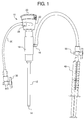
Figure 1 is an elevational view of a catheter; -
Figure 2 is an elevational view of the catheter with the cap open; -
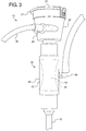
Figure 3 is an enlarged elevational view of the proximal portion of the catheter; -
Figure 4 is an end view of the catheter, showing the cap closed; -
Figure 5 is an end view of the catheter, showing the cap opened; -
Figure 6 is a cross-sectional view of the catheter, showing the cap closed and the first seal opened; -
Figure 7 is a cross-sectional view of the catheter, showing the cap opened and the first seal closed; -
Figure 8 is a perspective view of another embodiment of the catheter, showing the cap closed; and -
Figure 9 is a perspective view of the embodiment ofFigure 8 , showing the cap opened. - Referring now to the figures, and particularly to
Figure 1 , acatheter 10 is shown for collecting non-liquid masses, such as clots, thrombi, emboli or other masses. Thecatheter 10 is preferably used for collecting non-liquid masses from the vasculature and in particular the venous system. Thus, thecatheter 10 is provided with ashaft 12 that extends through an access site into a patient's body. The access site typically provides access to the venous system, and theshaft 12 will extend through a vein so that thedistal opening 14 of theshaft 12 is located next to the mass intended to be collected. Preferably, theshaft 12 is made of a flexible material like nylon or other polymers so that theshaft 12 can conform to the path of the vessel. The distal end of theshaft 12 is preferably atraumatic so that damage to the vessel wall is minimized. As illustrated inFigures 6-7 , theshaft 12 is hollow with alumen 16 extending from thedistal opening 14 to the proximal portion of thecatheter 10. - Along the proximal portion, the
catheter 10 includes afirst seal 18 that is capable of being closed to prevent fluid in theshaft lumen 16 from passing through thefirst seal 18 and escaping. Preferably, thefirst seal 18 can be actively controlled by the user so that theseal 18 can be actuated between a closed state and an open state. That is, the physician is able to open thefirst seal 18 and close thefirst seal 18 from outside thecatheter 10 without pushing a device through thefirst seal 18. Thefirst seal 18 may thus be thought of as a type of valve that can be closed to prevent fluid from escaping and opened when desired to allow the passage of medical devices and the mass to be collected. - A
cap 20 is located proximally from thefirst seal 18, and acollection chamber 22 is defined between thecap 20 and thefirst seal 18. InFigure 1 , thecap 20 is shown closed so that thecap 20 prevents fluid from escaping from thecatheter 10. However, as shown inFigure 2 , thecap 20 may be opened to provide access to thecollection chamber 22. Preferably, thecap 20 is attached to thecatheter 10 with ahinge 24 so that thecap 20 is not removable from thecatheter 10. This allows the physician to open and close thecap 20 as desired without concern for dropping or misplacing thecap 20, which could make thecap 20 unsterile or could risk excessive blood loss. Thecap 20 also preferably has alip 21 that extends outward from the outer surface of thecollection chamber 22 to allow the physician to easily grasp thecap 20 to open it. While thecap 20 may be oriented in various ways as desired, it is preferable for thecap 20 to extend across the axis of thecatheter shaft 12 when it is closed. This allows straight access into thecollection chamber 22 when thecap 20 is open to retrieve a collected mass. As shown inFigure 6 , asnap 26, such as an o-ring 26 or other detent, may also be provided to keep thecap 20 closed and prevent thecap 20 from inadvertently opening. Thesnap 26 may also help in sealing thecap 20 when it is closed to prevent fluid like blood from escaping from the outside of thecap 20. - In use, suction is applied to a
suction port 28 that is located along thecollection chamber 22. As shown inFigure 1 , ahose 30 may be attached to thesuction port 28, and avalve 32 may be provided on thehose 30 if desired to open and close communication with thesuction port 28. Various suction sources, such as a syringe or a vacuum machine, may be attached to thehose 30 orvalve 32. - Alternatively, a valve could be provided in or adjacent to the
suction port 28 and a suction source connected directly to the suction port 28 (though the suction source could use a hose for connection to the suction port 28). Such a valve might be actuable by the user, or might provide a non-actuable seal, opening in response to suction greater than a threshold amount (for example, having a magnitude greater than the pressure applied by fluid from the body within the collection chamber to the suction port 28) being applied to thesuction port 28. - While suction is being applied to the
suction port 28, thecap 20 is preferably closed and thefirst seal 18 is open as illustrated inFigure 6 . As a result, blood and the mass intended to be collected passes through thedistal opening 14 in theshaft 12 and through theshaft lumen 16. Since thefirst seal 18 is open, the material also passes through thefirst seal 18 and is received within thecollection chamber 22. As shown inFigures 6-7 , it may be desirable to provide afilter 29 in or adjacent to thesuction port 28 to prevent the non-liquid mass from passing through thesuction port 28. At this stage, the suction source may be shut off or thevalve 32 closed to stop further suctioning. In order to remove the mass from thecollection chamber 22, thefirst seal 18 is closed to prevent any additional fluid from escaping during the removal step. As illustrated inFigures 5 and7 , thecap 20 may now be opened without being concerned about additional blood escaping from thelumen 16 of theshaft 12. The material collected within thecollection chamber 22 may then be removed through thecap opening 34. If desired, forceps may be inserted through thecap opening 34 into thecollection chamber 22 to grasp the mass and pull it out of thecollection chamber 22. Once the mass has been removed, thecap 20 may be closed, thefirst seal 18 opened, and suction applied to thesuction port 28 again to collect additional material. This process may be repeated as needed to collect as much material as desired during the procedure. Between each collection step, thecatheter shaft 12 may be moved through the vessel to relocate thedistal opening 14 next to each mass intended to be collected. - The
collection chamber 22 will preferably be of a sufficient size to collect a non-liquid mass, such as a clot, thrombus or embolus. Thus, thecollection chamber 22 preferably has a cross-sectional area that is larger than the cross-sectional area of theshaft lumen 16. Thecap opening 34 is also preferably large enough to insert forceps to grasp the collected material. Thus, thecap opening 34 preferably has a diameter of 10 mm to 30 mm. Thecollection chamber 32 is preferably also anelongate chamber 22 along the length of the axis of theshaft 12 so that passage through thecap opening 34,collection chamber 22 andshaft lumen 16 is generally straight. However, thecollection chamber 22 need not be perfectly coaxial with theshaft lumen 16 and may have an offset shape as shown inFigures 8-9 . Thesuction port 28 preferably extends from aside wall 36 of thecollection chamber 22 so that theport 28 extends angularly from thechamber 22 with respect to the axis of thechamber 22. Thus, thesuction port 28 does not interfere with the straight passage of the mass through theshaft lumen 16,first seal 18,collection chamber 22 andcap opening 34. Although the size of thecollection chamber 22 may vary depending on the particular use of the device, a volume of 1 cc to 10 cc may be preferred to collect typical clots, thrombi and emboli. The length of thecollection chamber 22 between thefirst seal 18 and thecap 20 is also preferably 5 mm to 50 mm. - Although various types of
seals 18 are possible for thefirst seal 18, one type ofseal 18 that may be used for thefirst seal 18 is illustrated inFigures 3 and6-7 . This type ofseal 18 may have abladder 38 that circumferentially surrounds alumen 40 passing between theshaft lumen 16 and thecollection chamber 22. Thebladder 38 is typically made from athin material 38 that can flex and squeeze in upon itself as illustrated inFigure 7 to close theseal 18. Thebladder 38 may also flex outward to open thepassageway 40 between theshaft lumen 16 and thecollection chamber 22 as illustrated inFigure 6 . Movement of thebladder 38 between the closed state and the opened state is controlled by pressure in thepressure chamber 42 between the outer surface of thebladder 38 and anouter wall 44 of thefirst seal 18. Theouter wall 44 may be provided with apressure port 46 to apply pressure to thepressure chamber 42 to control opening and closing of thebladder 38. As shown inFigure 1 , asyringe 48 and avalve 50 may be connected to thepressure port 46 to apply pressure to thepressure chamber 42, and pressure may be retained to keep thefirst seal 18 closed by closing thevalve 50. Although less desirable, other types of seals may also be used for thefirst seal 18, such as a seal with an elastic member that is directly squeezed by twisting an outer housing. A valve, such as a ball valve may also be used for thefirst seal 18. - It may also be desirable to provide a
second seal 52 in thecap 20. Thesecond seal 52 may be generally aligned with thelumen 16 of theshaft 12 to allow medical devices to extend through thecatheter 10 while thecap 20 is closed. Thus, in the design ofFigures 8-9 , thesecond seal 52 is off-center in thecap 20 so that thesecond seal 52 is coaxial with theshaft lumen 16, since thecollection chamber 22 is offset. For example, in typical intraluminal procedures, access to the vasculature will first be obtained using a guidewire that extends through the overlapping tissues and into a vein or artery. The proximal portion of the guidewire remains outside of the patient to provide a pathway through the patient's tissues into the vein or artery. Once access has been gained with a guidewire, thedistal opening 14 may be threaded onto the guidewire, and thecatheter 10 may be slid onto the guidewire so that the guidewire extends through theshaft lumen 16, thefirst seal 18, thecollection chamber 22 and thesecond seal 52. Thecatheter 10 may then be threaded over the guidewire until theshaft 12 is located within the vein or artery. The guidewire may then be withdrawn from thecatheter 10 by pulling the guidewire proximally through thesecond seal 52. During this stage of the procedure, thefirst seal 18 preferably remains open so that thefirst seal 18 does not interfere with passage of the guidewire. Since thecap 20 remains closed during introduction of thecatheter 10 into the vasculature and thesecond seal 52 seals against the guidewire, blood will not escape even if thefirst seal 18 is open. Unlike thefirst seal 18, thesecond seal 52 may be anon-actuable seal 52, in that thesecond seal 52 passively seals and does not need to be separately controlled between an opened and closed state. Thus, thesecond seal 52 may be biased toward the closed state. Where thesecond seal 52 is passive, it is preferable for thesecond seal 52 to be bidirectional so that it seals both when suction is applied to thecollection chamber 22 and when blood pressure exists in thecollection chamber 22. Thus, as shown inFigure 6 , thesecond seal 52 extends perpendicular to the axis of theshaft lumen 16 and is not biased in either the proximal or distal direction. - While preferred embodiments of the inventions have been described, it should be understood that the inventions are not so limited, and modifications may be made without departing from the inventions herein. While each embodiment described herein may refer only to certain features and may not specifically refer to every feature described with respect to other embodiments, it should be recognized that the features described herein are interchangeable unless described otherwise, even where no reference is made to a specific feature. It should also be understood that the advantages described above are not necessarily the only advantages of the inventions, and it is not necessarily expected that all of the described advantages will be achieved with every embodiment of the inventions. The scope of the inventions is defined by the appended claims, and all devices and methods that come within the meaning of the claims, either literally or by equivalence, are intended to be embraced therein.
Claims (15)
- A catheter for removing a non-liquid mass from a body, comprising:a shaft adapted to extend through an access site into a patient's body to a distal opening within said patient's body, said shaft comprising a lumen extending therethrough in communication with said distal opening;a openable cap disposed along a proximal portion, said cap preventing fluid flow therethrough in a closed state and allowing said non-liquid mass to pass therethrough in an open state;a first seal in communication with said lumen and being disposed distal from said cap, said first seal being actuable between a closed state and an open state, said closed state preventing fluid flow therethrough and said open state allowing said non-liquid mass to pass therethrough;a collection chamber disposed between said cap and said first seal, said collection chamber being adapted to receive said non-liquid mass; anda suction port in communication with said collection chamber, said suction port being adapted such that, when a source of suction is connected thereto, said non-liquid mass is drawn through said lumen and said first seal into said collection chamber;wherein when said first seal actuated to said closed state and said cap is then opened to said open state, said non-liquid mass is thereby removable from said collection chamber while fluid is prevented from escaping said lumen by said first seal.
- The catheter according to claim 1, wherein said cap is attached to said catheter with a hinge, said cap thereby being non-removable.
- The catheter according to any preceding claim, further comprising a snap configured to retain said cap in said closed state.
- The catheter according to any preceding claim, wherein said cap extends across the axis of said shaft in said closed state.
- The catheter according to any preceding claim, further comprising a second seal in said cap, preferably wherein said second seal is adapted to allow a guidewire to pass therethrough, while preventing fluid flow therethrough.
- The catheter according to claim 5, wherein said second seal is a non-actuable seal, and said second seal is bidirectional and seals in response to pressure and suction.
- The catheter of claim 5 or claim 6, wherein said second seal is aligned with the lumen of the shaft.
- The catheter according to any preceding claim, wherein a volume of said collection chamber is 1 cc to 10 cc.
- The catheter according toany preceding claim, wherein a length of said collection chamber is 5 mm to 50 mm.
- The catheter according to any preceding claim, wherein the cross-sectional area of said collection chamber is larger than the cross-sectional area of said lumen.
- The catheter according to any preceding claim, wherein said collection chamber is elongated along an axis of said shaft.
- The catheter according to any preceding claim, wherein said first seal comprises a bladder and a pressure chamber, said bladder closing in said closed state in response to pressure within said pressure chamber and opening in said open state in response to releasing said pressure from within said pressure chamber.
- The catheter according to any preceding claim, wherein said collection chamber defines an axis that extends between said first seal and said openable cap and wherein said port is provided in a side of said collection chamber with respect to said axis.
- The catheter according to any preceding claim, wherein said collection chamber defines an axis that extends between said first seal and said openable cap and wherein said port extends angularly from said collection chamber with respect to said axis.
- The catheter according to any preceding claim, further comprising a filter preventing said non-liquid mass from passing through said suction port.
Applications Claiming Priority (1)
| Application Number | Priority Date | Filing Date | Title |
|---|---|---|---|
| US201462089648P | 2014-12-09 | 2014-12-09 |
Publications (2)
| Publication Number | Publication Date |
|---|---|
| EP3031412A1 true EP3031412A1 (en) | 2016-06-15 |
| EP3031412B1 EP3031412B1 (en) | 2020-04-01 |
Family
ID=54848429
Family Applications (1)
| Application Number | Title | Priority Date | Filing Date |
|---|---|---|---|
| EP15198742.7A Active EP3031412B1 (en) | 2014-12-09 | 2015-12-09 | Catheter with a collection chamber |
Country Status (2)
| Country | Link |
|---|---|
| US (1) | US10456152B2 (en) |
| EP (1) | EP3031412B1 (en) |
Families Citing this family (5)
| Publication number | Priority date | Publication date | Assignee | Title |
|---|---|---|---|---|
| US11154314B2 (en) * | 2018-01-26 | 2021-10-26 | Inari Medical, Inc. | Single insertion delivery system for treating embolism and associated systems and methods |
| US11654227B1 (en) * | 2019-06-20 | 2023-05-23 | Sang In Han | Wet seal suction device |
| KR20220100672A (en) * | 2019-11-14 | 2022-07-15 | 아비오메드, 인크. | Hemostatic valve for sheath assembly |
| CN112206399A (en) * | 2020-09-18 | 2021-01-12 | 合肥晟宏医疗器械有限公司 | Vascular catheter sheath assembly |
| CN114452049B (en) * | 2022-03-14 | 2025-11-25 | 上海纽脉医疗科技股份有限公司 | A sealing structure |
Citations (5)
| Publication number | Priority date | Publication date | Assignee | Title |
|---|---|---|---|---|
| US5827229A (en) * | 1995-05-24 | 1998-10-27 | Boston Scientific Corporation Northwest Technology Center, Inc. | Percutaneous aspiration thrombectomy catheter system |
| US20050137498A1 (en) * | 2003-12-23 | 2005-06-23 | Robert Sakal | Medical instrument for accessing a breast duct for performing a medical procedure |
| US20060129091A1 (en) * | 2004-12-10 | 2006-06-15 | Possis Medical, Inc. | Enhanced cross stream mechanical thrombectomy catheter with backloading manifold |
| US20090036871A1 (en) * | 2002-07-15 | 2009-02-05 | Motoya Hayase | Material removal catheter and method |
| US8057497B1 (en) * | 2009-07-28 | 2011-11-15 | Seshadri Raju | Thrombectomy removal device kit |
Family Cites Families (2)
| Publication number | Priority date | Publication date | Assignee | Title |
|---|---|---|---|---|
| US20140081075A1 (en) * | 2006-08-15 | 2014-03-20 | Fouad A. Salama | Urinary incontinence device |
| US20130317529A1 (en) * | 2010-12-03 | 2013-11-28 | Steven S. Golden | Methods and devices for metabolic surgery |
-
2015
- 2015-12-08 US US14/962,086 patent/US10456152B2/en active Active
- 2015-12-09 EP EP15198742.7A patent/EP3031412B1/en active Active
Patent Citations (5)
| Publication number | Priority date | Publication date | Assignee | Title |
|---|---|---|---|---|
| US5827229A (en) * | 1995-05-24 | 1998-10-27 | Boston Scientific Corporation Northwest Technology Center, Inc. | Percutaneous aspiration thrombectomy catheter system |
| US20090036871A1 (en) * | 2002-07-15 | 2009-02-05 | Motoya Hayase | Material removal catheter and method |
| US20050137498A1 (en) * | 2003-12-23 | 2005-06-23 | Robert Sakal | Medical instrument for accessing a breast duct for performing a medical procedure |
| US20060129091A1 (en) * | 2004-12-10 | 2006-06-15 | Possis Medical, Inc. | Enhanced cross stream mechanical thrombectomy catheter with backloading manifold |
| US8057497B1 (en) * | 2009-07-28 | 2011-11-15 | Seshadri Raju | Thrombectomy removal device kit |
Also Published As
| Publication number | Publication date |
|---|---|
| US20160157873A1 (en) | 2016-06-09 |
| US10456152B2 (en) | 2019-10-29 |
| EP3031412B1 (en) | 2020-04-01 |
Similar Documents
| Publication | Publication Date | Title |
|---|---|---|
| US11850349B2 (en) | Vacuum transfer tool for extendable catheter | |
| US10456152B2 (en) | Catheter with a collection chamber | |
| JP7082572B2 (en) | Fluid transfer device and method with placed peripheral venous catheter | |
| US8251975B2 (en) | Catheter and tunneling device therefor | |
| RU2688010C2 (en) | Systems and methods for phlebotomy through peripheral intravenous catheter | |
| JP2023511958A (en) | Aspiration catheter system designed for rapid clot removal | |
| US11701141B2 (en) | Occludable introducer needle | |
| US11672640B2 (en) | Thrombectomy filter and method for performing a thrombectomy | |
| US20040019310A1 (en) | Blood aspiration system and methods of use | |
| US20080051708A1 (en) | Surgical aspiration system and method of surgical aspiration | |
| US7449010B1 (en) | Material removal catheter and method | |
| US20250261956A1 (en) | Devices and methods for enhanced aspiration-induced thrombectomy | |
| US20090221950A1 (en) | Catheter and tunneling device therefor | |
| JPH04227272A (en) | Medical catheter apparatus | |
| US20130150767A1 (en) | Vascular access device for hemodialysis | |
| EP2769744A1 (en) | Medical product and medical set for the drainage of pathological accumulation of fluids | |
| US20250177625A1 (en) | Filtering devices, such as for use with clot treatment systems, and associated systems and methods | |
| WO2026055983A1 (en) | Negative pressure suction sheath | |
| KR20050013927A (en) | Sheath with air trap | |
| JP2024532430A (en) | Percutaneous vascular occlusion detection and pressure relief | |
| KR101622245B1 (en) | Apparatus for fixing catheter | |
| US20070016136A1 (en) | Suction hand-piece device with variable control off/on valve | |
| CN118680627A (en) | Negative pressure suction device, negative pressure suction method and application thereof | |
| US20140371725A1 (en) | Motion-assisted systems, devices and methods for minimizing obstruction of medical devices | |
| US11134980B2 (en) | Occludable introducer needle |
Legal Events
| Date | Code | Title | Description |
|---|---|---|---|
| PUAI | Public reference made under article 153(3) epc to a published international application that has entered the european phase |
Free format text: ORIGINAL CODE: 0009012 |
|
| AK | Designated contracting states |
Kind code of ref document: A1 Designated state(s): AL AT BE BG CH CY CZ DE DK EE ES FI FR GB GR HR HU IE IS IT LI LT LU LV MC MK MT NL NO PL PT RO RS SE SI SK SM TR |
|
| AX | Request for extension of the european patent |
Extension state: BA ME |
|
| STAA | Information on the status of an ep patent application or granted ep patent |
Free format text: STATUS: REQUEST FOR EXAMINATION WAS MADE |
|
| 17P | Request for examination filed |
Effective date: 20161215 |
|
| RBV | Designated contracting states (corrected) |
Designated state(s): AL AT BE BG CH CY CZ DE DK EE ES FI FR GB GR HR HU IE IS IT LI LT LU LV MC MK MT NL NO PL PT RO RS SE SI SK SM TR |
|
| RIC1 | Information provided on ipc code assigned before grant |
Ipc: A61B 17/22 20060101AFI20190827BHEP |
|
| GRAP | Despatch of communication of intention to grant a patent |
Free format text: ORIGINAL CODE: EPIDOSNIGR1 |
|
| STAA | Information on the status of an ep patent application or granted ep patent |
Free format text: STATUS: GRANT OF PATENT IS INTENDED |
|
| INTG | Intention to grant announced |
Effective date: 20191021 |
|
| GRAS | Grant fee paid |
Free format text: ORIGINAL CODE: EPIDOSNIGR3 |
|
| GRAA | (expected) grant |
Free format text: ORIGINAL CODE: 0009210 |
|
| STAA | Information on the status of an ep patent application or granted ep patent |
Free format text: STATUS: THE PATENT HAS BEEN GRANTED |
|
| AK | Designated contracting states |
Kind code of ref document: B1 Designated state(s): AL AT BE BG CH CY CZ DE DK EE ES FI FR GB GR HR HU IE IS IT LI LT LU LV MC MK MT NL NO PL PT RO RS SE SI SK SM TR |
|
| REG | Reference to a national code |
Ref country code: GB Ref legal event code: FG4D |
|
| REG | Reference to a national code |
Ref country code: AT Ref legal event code: REF Ref document number: 1250330 Country of ref document: AT Kind code of ref document: T Effective date: 20200415 Ref country code: CH Ref legal event code: EP |
|
| REG | Reference to a national code |
Ref country code: DE Ref legal event code: R096 Ref document number: 602015049753 Country of ref document: DE |
|
| REG | Reference to a national code |
Ref country code: IE Ref legal event code: FG4D |
|
| PG25 | Lapsed in a contracting state [announced via postgrant information from national office to epo] |
Ref country code: BG Free format text: LAPSE BECAUSE OF FAILURE TO SUBMIT A TRANSLATION OF THE DESCRIPTION OR TO PAY THE FEE WITHIN THE PRESCRIBED TIME-LIMIT Effective date: 20200701 |
|
| REG | Reference to a national code |
Ref country code: NL Ref legal event code: MP Effective date: 20200401 |
|
| REG | Reference to a national code |
Ref country code: LT Ref legal event code: MG4D |
|
| PG25 | Lapsed in a contracting state [announced via postgrant information from national office to epo] |
Ref country code: PT Free format text: LAPSE BECAUSE OF FAILURE TO SUBMIT A TRANSLATION OF THE DESCRIPTION OR TO PAY THE FEE WITHIN THE PRESCRIBED TIME-LIMIT Effective date: 20200817 Ref country code: LT Free format text: LAPSE BECAUSE OF FAILURE TO SUBMIT A TRANSLATION OF THE DESCRIPTION OR TO PAY THE FEE WITHIN THE PRESCRIBED TIME-LIMIT Effective date: 20200401 Ref country code: SE Free format text: LAPSE BECAUSE OF FAILURE TO SUBMIT A TRANSLATION OF THE DESCRIPTION OR TO PAY THE FEE WITHIN THE PRESCRIBED TIME-LIMIT Effective date: 20200401 Ref country code: NL Free format text: LAPSE BECAUSE OF FAILURE TO SUBMIT A TRANSLATION OF THE DESCRIPTION OR TO PAY THE FEE WITHIN THE PRESCRIBED TIME-LIMIT Effective date: 20200401 Ref country code: GR Free format text: LAPSE BECAUSE OF FAILURE TO SUBMIT A TRANSLATION OF THE DESCRIPTION OR TO PAY THE FEE WITHIN THE PRESCRIBED TIME-LIMIT Effective date: 20200702 Ref country code: NO Free format text: LAPSE BECAUSE OF FAILURE TO SUBMIT A TRANSLATION OF THE DESCRIPTION OR TO PAY THE FEE WITHIN THE PRESCRIBED TIME-LIMIT Effective date: 20200701 Ref country code: CZ Free format text: LAPSE BECAUSE OF FAILURE TO SUBMIT A TRANSLATION OF THE DESCRIPTION OR TO PAY THE FEE WITHIN THE PRESCRIBED TIME-LIMIT Effective date: 20200401 Ref country code: FI Free format text: LAPSE BECAUSE OF FAILURE TO SUBMIT A TRANSLATION OF THE DESCRIPTION OR TO PAY THE FEE WITHIN THE PRESCRIBED TIME-LIMIT Effective date: 20200401 Ref country code: IS Free format text: LAPSE BECAUSE OF FAILURE TO SUBMIT A TRANSLATION OF THE DESCRIPTION OR TO PAY THE FEE WITHIN THE PRESCRIBED TIME-LIMIT Effective date: 20200801 |
|
| REG | Reference to a national code |
Ref country code: AT Ref legal event code: MK05 Ref document number: 1250330 Country of ref document: AT Kind code of ref document: T Effective date: 20200401 |
|
| PG25 | Lapsed in a contracting state [announced via postgrant information from national office to epo] |
Ref country code: RS Free format text: LAPSE BECAUSE OF FAILURE TO SUBMIT A TRANSLATION OF THE DESCRIPTION OR TO PAY THE FEE WITHIN THE PRESCRIBED TIME-LIMIT Effective date: 20200401 Ref country code: LV Free format text: LAPSE BECAUSE OF FAILURE TO SUBMIT A TRANSLATION OF THE DESCRIPTION OR TO PAY THE FEE WITHIN THE PRESCRIBED TIME-LIMIT Effective date: 20200401 Ref country code: HR Free format text: LAPSE BECAUSE OF FAILURE TO SUBMIT A TRANSLATION OF THE DESCRIPTION OR TO PAY THE FEE WITHIN THE PRESCRIBED TIME-LIMIT Effective date: 20200401 |
|
| PG25 | Lapsed in a contracting state [announced via postgrant information from national office to epo] |
Ref country code: AL Free format text: LAPSE BECAUSE OF FAILURE TO SUBMIT A TRANSLATION OF THE DESCRIPTION OR TO PAY THE FEE WITHIN THE PRESCRIBED TIME-LIMIT Effective date: 20200401 |
|
| REG | Reference to a national code |
Ref country code: DE Ref legal event code: R097 Ref document number: 602015049753 Country of ref document: DE |
|
| PG25 | Lapsed in a contracting state [announced via postgrant information from national office to epo] |
Ref country code: EE Free format text: LAPSE BECAUSE OF FAILURE TO SUBMIT A TRANSLATION OF THE DESCRIPTION OR TO PAY THE FEE WITHIN THE PRESCRIBED TIME-LIMIT Effective date: 20200401 Ref country code: SM Free format text: LAPSE BECAUSE OF FAILURE TO SUBMIT A TRANSLATION OF THE DESCRIPTION OR TO PAY THE FEE WITHIN THE PRESCRIBED TIME-LIMIT Effective date: 20200401 Ref country code: IT Free format text: LAPSE BECAUSE OF FAILURE TO SUBMIT A TRANSLATION OF THE DESCRIPTION OR TO PAY THE FEE WITHIN THE PRESCRIBED TIME-LIMIT Effective date: 20200401 Ref country code: RO Free format text: LAPSE BECAUSE OF FAILURE TO SUBMIT A TRANSLATION OF THE DESCRIPTION OR TO PAY THE FEE WITHIN THE PRESCRIBED TIME-LIMIT Effective date: 20200401 Ref country code: ES Free format text: LAPSE BECAUSE OF FAILURE TO SUBMIT A TRANSLATION OF THE DESCRIPTION OR TO PAY THE FEE WITHIN THE PRESCRIBED TIME-LIMIT Effective date: 20200401 Ref country code: AT Free format text: LAPSE BECAUSE OF FAILURE TO SUBMIT A TRANSLATION OF THE DESCRIPTION OR TO PAY THE FEE WITHIN THE PRESCRIBED TIME-LIMIT Effective date: 20200401 Ref country code: DK Free format text: LAPSE BECAUSE OF FAILURE TO SUBMIT A TRANSLATION OF THE DESCRIPTION OR TO PAY THE FEE WITHIN THE PRESCRIBED TIME-LIMIT Effective date: 20200401 |
|
| PLBE | No opposition filed within time limit |
Free format text: ORIGINAL CODE: 0009261 |
|
| STAA | Information on the status of an ep patent application or granted ep patent |
Free format text: STATUS: NO OPPOSITION FILED WITHIN TIME LIMIT |
|
| PG25 | Lapsed in a contracting state [announced via postgrant information from national office to epo] |
Ref country code: SK Free format text: LAPSE BECAUSE OF FAILURE TO SUBMIT A TRANSLATION OF THE DESCRIPTION OR TO PAY THE FEE WITHIN THE PRESCRIBED TIME-LIMIT Effective date: 20200401 Ref country code: PL Free format text: LAPSE BECAUSE OF FAILURE TO SUBMIT A TRANSLATION OF THE DESCRIPTION OR TO PAY THE FEE WITHIN THE PRESCRIBED TIME-LIMIT Effective date: 20200401 |
|
| 26N | No opposition filed |
Effective date: 20210112 |
|
| PG25 | Lapsed in a contracting state [announced via postgrant information from national office to epo] |
Ref country code: SI Free format text: LAPSE BECAUSE OF FAILURE TO SUBMIT A TRANSLATION OF THE DESCRIPTION OR TO PAY THE FEE WITHIN THE PRESCRIBED TIME-LIMIT Effective date: 20200401 |
|
| REG | Reference to a national code |
Ref country code: CH Ref legal event code: PL |
|
| PG25 | Lapsed in a contracting state [announced via postgrant information from national office to epo] |
Ref country code: MC Free format text: LAPSE BECAUSE OF FAILURE TO SUBMIT A TRANSLATION OF THE DESCRIPTION OR TO PAY THE FEE WITHIN THE PRESCRIBED TIME-LIMIT Effective date: 20200401 |
|
| REG | Reference to a national code |
Ref country code: BE Ref legal event code: MM Effective date: 20201231 |
|
| PG25 | Lapsed in a contracting state [announced via postgrant information from national office to epo] |
Ref country code: FR Free format text: LAPSE BECAUSE OF NON-PAYMENT OF DUE FEES Effective date: 20201231 Ref country code: LU Free format text: LAPSE BECAUSE OF NON-PAYMENT OF DUE FEES Effective date: 20201209 |
|
| PG25 | Lapsed in a contracting state [announced via postgrant information from national office to epo] |
Ref country code: CH Free format text: LAPSE BECAUSE OF NON-PAYMENT OF DUE FEES Effective date: 20201231 Ref country code: LI Free format text: LAPSE BECAUSE OF NON-PAYMENT OF DUE FEES Effective date: 20201231 |
|
| PG25 | Lapsed in a contracting state [announced via postgrant information from national office to epo] |
Ref country code: TR Free format text: LAPSE BECAUSE OF FAILURE TO SUBMIT A TRANSLATION OF THE DESCRIPTION OR TO PAY THE FEE WITHIN THE PRESCRIBED TIME-LIMIT Effective date: 20200401 Ref country code: MT Free format text: LAPSE BECAUSE OF FAILURE TO SUBMIT A TRANSLATION OF THE DESCRIPTION OR TO PAY THE FEE WITHIN THE PRESCRIBED TIME-LIMIT Effective date: 20200401 Ref country code: CY Free format text: LAPSE BECAUSE OF FAILURE TO SUBMIT A TRANSLATION OF THE DESCRIPTION OR TO PAY THE FEE WITHIN THE PRESCRIBED TIME-LIMIT Effective date: 20200401 |
|
| PG25 | Lapsed in a contracting state [announced via postgrant information from national office to epo] |
Ref country code: MK Free format text: LAPSE BECAUSE OF FAILURE TO SUBMIT A TRANSLATION OF THE DESCRIPTION OR TO PAY THE FEE WITHIN THE PRESCRIBED TIME-LIMIT Effective date: 20200401 |
|
| PG25 | Lapsed in a contracting state [announced via postgrant information from national office to epo] |
Ref country code: BE Free format text: LAPSE BECAUSE OF NON-PAYMENT OF DUE FEES Effective date: 20201231 |
|
| P01 | Opt-out of the competence of the unified patent court (upc) registered |
Effective date: 20230602 |
|
| PGFP | Annual fee paid to national office [announced via postgrant information from national office to epo] |
Ref country code: GB Payment date: 20251223 Year of fee payment: 11 |
|
| PGFP | Annual fee paid to national office [announced via postgrant information from national office to epo] |
Ref country code: IE Payment date: 20251218 Year of fee payment: 11 |
|
| PGFP | Annual fee paid to national office [announced via postgrant information from national office to epo] |
Ref country code: DE Payment date: 20251229 Year of fee payment: 11 |