EP3031098B1 - Standard antenna interface - Google Patents
Standard antenna interface Download PDFInfo
- Publication number
- EP3031098B1 EP3031098B1 EP14758196.1A EP14758196A EP3031098B1 EP 3031098 B1 EP3031098 B1 EP 3031098B1 EP 14758196 A EP14758196 A EP 14758196A EP 3031098 B1 EP3031098 B1 EP 3031098B1
- Authority
- EP
- European Patent Office
- Prior art keywords
- float
- antenna
- connector
- gasket
- interconnection module
- Prior art date
- Legal status (The legal status is an assumption and is not a legal conclusion. Google has not performed a legal analysis and makes no representation as to the accuracy of the status listed.)
- Not-in-force
Links
Images










Classifications
-
- H—ELECTRICITY
- H01—ELECTRIC ELEMENTS
- H01Q—ANTENNAS, i.e. RADIO AERIALS
- H01Q1/00—Details of, or arrangements associated with, antennas
- H01Q1/12—Supports; Mounting means
- H01Q1/22—Supports; Mounting means by structural association with other equipment or articles
- H01Q1/24—Supports; Mounting means by structural association with other equipment or articles with receiving set
- H01Q1/241—Supports; Mounting means by structural association with other equipment or articles with receiving set used in mobile communications, e.g. GSM
- H01Q1/246—Supports; Mounting means by structural association with other equipment or articles with receiving set used in mobile communications, e.g. GSM specially adapted for base stations
-
- H—ELECTRICITY
- H01—ELECTRIC ELEMENTS
- H01Q—ANTENNAS, i.e. RADIO AERIALS
- H01Q1/00—Details of, or arrangements associated with, antennas
- H01Q1/12—Supports; Mounting means
Definitions
- the present inventions relate generally to wireless communications. In particular, they relate to improvements in wireless base station antenna and radio deployments.
- a traditional installation of a wireless radio network system mounted at the top of the tower consists of a remote radio head (RRH) and a separate antenna. These components are mounted in separate locations and are cabled together using jumper cables to pass the radio frequency (RF) signal between them.
- RRH remote radio head
- RF radio frequency
- Jumper cables present RF losses and Passive Intermodulation products (PIM) performance issues. These issues degrade network performance, and add significant cost to the network operator to overcome. Jumper cables also require more weatherproofing, and additional capital expense and operating expense.
- PIM Passive Intermodulation products
- Integrated antennas do not provide flexibility for the network operator to select different RRHs or Antennas from different suppliers.
- the radio network operator is limited to the supplier of the active or integrated antenna and the performance and price of that system.
- the Integrated antenna approach also restricts the ability of the operator to leverage supplier diversity for the antenna products, or for the RRH units. It also limits the availability of new beamwidth antennas, as well as multi-beam antennas. The operator is further challenged to stock spares of expensive combined units.
- Antennas are passive components and have an inherently lower failure rate than do Remote Radio Heads. Typical antenna return rates are less than 0.1% annually, while RRH return rates range from 3% to 5% typically. Thus, integrating an antenna and RRH in a single unit on the tower would require antennas to be replaced at the same rate as RRH's, increasing operating expenses.
- WO 2013/071206 A1 discloses a connector with a capacitively coupled connector interface for interconnection with a female portion.
- the connector has an annular groove, with a sidewall, open to an interface end of the female portion.
- a male portion is provided with a male outer conductor coupling surface at an interface end, covered by an outer conductor dielectric spacer.
- the male portion is retained with a range of radial movement, with respect to a longitudinal axis of the male portion, by a bias web of a float plate.
- the male outer conductor coupling surface is dimensioned to seat, spaced apart from the sidewall by the outer conductor dielectric spacer, within the annular groove, when the male portion and the female portion are in an interlocked position.
- US 2010/079346 A1 describes an enclosure system for a radio board and an antenna circuit, having a downwardly opening, concave housing with an interior housing cavity, a base that fits across the bottom of the housing, and a mounting plate that mounts on the base and extends into the housing cavity.
- the radio board and antenna mount on the mounting plate.
- a transparent cable access door has spaced knockouts that allow routing of communication interface cables.
- Mounting bolts attached to the exterior of the housing allow mounting of a mounting bracket.
- the bottom of the base is flat for placement on a flat surface.
- the present invention provides an RF interconnection module and a mount assembly as defined in the appended claims.
- An RF interconnection module includes a housing having a perimeter, a capacitive coupling at least partially disposed in the housing, and a float gasket disposed about the perimeter of the housing.
- the float gasket When the housing is mounted in an opening, the float gasket is positioned between the housing and the opening.
- the float gasket may be made of an elastomer material, and may include a first flange, a second flange and a middle portion. The first flange and the second flange may be operable to secure the float gasket in the opening, and the middle portion may include a plurality of outwardly extending ribs for movable securing the gasket in the opening.
- the RF interconnection module may include a float plate disposed in the housing.
- the capacitive coupling may be movably disposed in the float plate so that the capacitive coupling may move with respect to the housing.
- the float plate may be made of an elastomer material.
- the float plate may include a plurality of flexibly fingers that define an aperture for receiving the capacitive coupling. The flexible fingers may operate to movably secure the capacitive coupling in the aperture.
- a mount assembly in another aspect of the present disclosure, includes a bracket assembly attachable to a tower-mounted equipment and at least one jumper cable having at least one ohmic connector for connecting to the tower-mounted equipment and at least one capacitive connector.
- the capacitive connector may comprise an RF interconnection module mounted on the bracket assembly.
- the RF interconnection module may include a float gasket for movably mounting the RF interconnection module on the bracket assembly.
- the mount assembly may include at least one diplexer having a low friction car configured to engage a linear guided support member of a radio head mount.
- the bracket assembly may be adjustable to accommodate tower mounted equipment of various sizes.
- a Standard Antenna Interface is described herein to overcome the limitations of a traditional RRH and antenna tower top installation.
- This disclosure creates a standard antenna interface that provides a reduced installation time, prevents the installer from directly touching/interfacing with the RF electrical path, creates a PIM free interface, and allows the network operator the flexibility to select any brand of antenna or RRH to install.
- This solution further enables the stocking of separate antennas and RRH's, thus reducing the cost of inventory.
- the higher failure rate RRH's can be replaced independently of the more reliable passive antennas.
- the Standard Antenna Interface comprises of a standard interface structure, including antenna mounting brackets and RRH mounting structure, and a RF interconnection module.
- the standard interface structure acts as the mounting medium for both the antenna and the RRH. Both the antenna and RRH are mounted to their respective universal mounting structure.
- One mounting structure will receive the antenna and, optionally, all necessary interconnects, where the other bracket or mounting structure will receive the RRH and, optionally necessary interconnects.
- the Standard Interface Structure does not include RF interconnects, such RF interconnects are made directly between the antenna and the RRH.
- Each entity will mount directly to the standard interface structure and can be removed independently from each other.
- the Standard Antenna Interface allows antennas and radios from different manufacturers to be coupled together in the field without adding jumper cables and/or ohmic connections.
- an Upper Tower Mount 12, and Middle Tower Mount 14 and a Lower Tower Mount 16 are mounted on a Mounting Pole 18.
- the Upper Tower Mount 12, and Middle Tower Mount 14 and a Lower Tower Mount 16 are configured to mechanically interface with a plurality of Remote Radio Heads 20 and an Antenna 22.
- the Upper Tower Mount 12, and Middle Tower Mount 14 and a Lower Tower Mount 16 are configured to mechanically interface with a Diplexer 24 placed between a Remote Radio Head 20 and the Antenna 22.
- the example illustrated in Figures land 2 allows for the installation of up to four Remote Radio Heads 20.
- the Middle Tower Mount 14 may be omitted.
- the Upper Tower Mount 12 and the Lower Tower Mount 16 each include a Linear Guided Support 26.
- the Linear Guided Supports 26 comprise tracks that are configured to receive a roller trolley.
- alternative track and low friction car slide structures are within the scope of this disclosure and may be substituted.
- the Upper Tower Mount 12 includes an Antenna Mount 28.
- An additional Antenna Mount 29 is included on the Mounting Pole 18.
- the Antenna 22 includes Brackets 30, which include slots to engage Antenna Mount 28 and Antenna Mount 29.
- Middle Tower Mount 14 includes two Linear Guided Supports 26.
- the Linear Guided Supports 26 are on the opposite side of the Mounting Pole 18 from the Antenna 22 and extend away from the Antenna 22.
- the Lower Tower Mount 16 may be structurally the same as Upper Tower Mount 12, but is inverted when mounted.
- the Upper Tower Mount 12 and the Lower Tower Mount 16 each include an Antenna Mount 28 in this example.
- the Remote Radio Head 20 includes an Upper Low Friction Car 32 and a Lower Low Friction Car 34.
- the Upper Low Friction Car 32 and a Lower Low Friction Car 34 each engage a respective Linear Guided Support 26.
- the Upper Low Friction Car 32 engages a Linear Guided Support 26 of the Middle Tower Mount 14
- the Lower Low Friction Car 34 engages the Linear Guided Support 26 of the Lower Tower Mount 16.
- the Upper Low Friction Car 32 and the Lower Low Friction Car 34 each comprise a wheeled trolley.
- alternative low friction non-wheeled cars are also contemplated and may be substituted for the wheeled trolleys.
- Each Remote Radio Head 20 includes a RRH Connector 40.
- the Antenna 20 includes a plurality of integrated RF Interconnection Modules 44 designed to engage a respective mating RRH Connector 40.
- the RF Interconnection Module 44 may be located on the Standard Antenna Interface 10, and the Antenna 20 may be provided with a connector.
- the Remote Radio Head 20 may then slide into engagement with Antenna 22. Specifically, the RRH connector 40 is mated with its respective RF Interconnection Module 44.
- the Remote Radio Head 20 may mate directly with the antenna, or optionally, a Diplexer 24 may be included between two Remote Radio Heads 20 and the Antenna 22.
- the Remote Radio Head 20 may be locked into place with Lock 35.
- the Diplexer 24 When a Diplexer 24 is used, the Diplexer 24 will include two sets of RF Interconnection Modules 44 facing the Remote Radio Heads 20.
- the Diplexer 24 also includes one RRH Connector 40 facing the Antenna 22.
- the Antenna 22 may be configured to have a single RF Interconnection Module 44 facing the Diplexer 24.
- the Diplexer 24 includes a pair of Upper Low Friction Cars 32 and a pair of Lower Low Friction Cars 34.
- additional types of tower-mountable equipment, such as filters may be accommodated by the Standard Antenna Interface 10.
- An assembly may comprise as few as one antenna and one Remote Radio Head 20.
- each Linear Guided Support 26 may include two channels to accept two Remote Radio Heads 20, and there may be more than one pair of Linear Guided Supports 26 for each Antenna 22. In the illustrated examples, there may be four Remote Radio Heads 20 coupled to the Antenna 22.
- Figures 1-4 enable straight-in, linear engagement of the RF connectors. This allows for an improved design of blind-matable, capacitively coupled RF connectors to be employed. An example of such a long-engagement is illustrated in Figures 5 and 6 .
- RF Interconnection Module 44 and RRH Connector 40 may comprise a blind mate connector of coaxial construction.
- the RF Interconnection Module 44 may include includes a central conductor extension having a generally Cylindrical Post 60 and an Outer Conductor Extension 62.
- the Cylindrical Post 60 may be covered by a dielectric layer, such as one formed of a polymeric shrink sleeve.
- the RRH Connector 40 may include a Central Conductor Extension 64 that is adapted to receive the Cylindrical Post 60 of the RF Interconnection Module 44, and an Outer Conductor Extension 66 configured to fit within the Outer Conductor Extension 62.
- a dielectric layer overlies the Outer Conductor Extension 66. The dielectric layers prevent an ohmic connection between the conductor extensions and ensure that the coupling is capacitive, reducing the possibility of Passive Intermodulation (PIM).
- PIM Passive Intermodulation
- the RF Interconnection Module 44 may include a float plate to improve alignment of capacitive, blind mate connectors.
- a float plate to improve alignment of capacitive, blind mate connectors.
- FIGs 7a and 7b portions of an Interconnection Module 44 including a Float Plate 70 are illustrated.
- the float plate 70 may receive blind mated coaxial connectors within each opening; four such interconnections, designated at 72 illustrated in Figures 7a and 7b .
- the float plate 70 is typically mounted to a rigid structure, such as a back of an antenna, that includes openings that align with the openings in the float plate 70.
- the openings in the rigid structure are sufficiently large that they do not interfere with flexure of the fingers 76 normal to the main body panel 78. Exemplary environments in which float plates may be employed with blind-matable connectors are discussed in U.S. Patent Publication No. 2013/0065415 to Van Swearingen et al. .
- the Standard Antenna Interface 110 mounts away from the pole or the wall and houses the Antenna 122 and Remote Radio Head 120 on one side of the pole.
- the Standard Antenna Interface 110 is constructed out of formed sheet metal.
- the Standard Antenna Interface 110 may also be constructed out of metal rectangular tubing.
- an RF Interconnection Module 144 is integrated into Antenna 122 ( Fig. 10a ).
- a Remote Radio Head may be connected to the Standard Antenna Interface 110.
- the Remote Radio Head 120 includes mounting a hooked Mounting Bracket 127 and a slotted Mounting Bracket 128.
- the Standard Antenna Interface 110 includes Pins 129, which comprise axially guided support structure. The hooked Mounting Bracket 127 and a slotted Mounting Bracket 128 engage the Pins 129 of the Standard Antenna Interface ( Fig. 9a ), and allow the Remote Radio Head 120 to rotate into engagement ( Fig. 9b ).
- the Standard Antenna Interface 110 may be configured receive two or more Remote Radio Heads 120.
- the Antenna 122 also has a hooked Mounting Bracket 127 (not illustrated) and a slotted Mounting Bracket 128 that engages Pins 129 and allows Antenna 122 to be rotated into engagement in a similar manner.
- the Remote Radio Head 120 may be installed and/or removed from the Standard Antenna Interface 110 without moving the Antenna 122 (10a).
- the Antenna 122 may be installed and/or removed from the Standard Antenna Interface 110 without moving the Remote Radio Head 120 (10b).
- the hooked Mounting Bracket 127 and the slotted Mounting Bracket 128 may be replaced with a single piece mounting bracket.
- the linear guided support structure and the axially guided support structure may also be used in combination.
- an antenna may be mounted using the axially guided support structure, such as Pins 129 and corresponding Hooked Mounting Bracket 127, and tower mountable equipment may be installed using Linearly Guided Supports 26 and Low Friction Cars 32, 34.
- the Standard Antenna Interface 210 accommodates an Antenna 222 and up to four RRH Remote Radio Heads 220.
- the Standard Antenna Interface 210 is mounted to a pole.
- the Standard Antenna Interface 210 includes Cross Members 212, 214, and 216, and a Vertical Member 217.
- the Standard Antenna Interface 210 includes Mounting Points 228 for the Antenna 222 and RF Interconnection Modules 244.
- an Antenna 222 mounted to the Standard Antenna Interface 210.
- Mounting Brackets 229 for receiving Remote Radio Heads 120 are also installed on the Standard Antenna Interface 210 in an upper position.
- Float Plates 270 may be included on the Mounting Brackets 229.
- an optional Diplexer 224 is mounted on the Standard Antenna Interface 210.
- Figure 14 continues the example of Figure 13 , with the inclusion of Mounting Brackets 229 being installed on the Diplexer 224.
- the Remote Radio Heads 220 may be mounted on the Diplexer 224 in the same way that they would be mounted directly to the Standard Antenna Interface 210.
- the Mounting Brackets 224 include an RF Interconnection Module 244, which interfaces with Antenna Connector 242 and connectors on the Remote Radio Head (not illustrated).
- Diplexer 224 The installation of the Diplexer 224 on the lower mounting brackets is just one example; a Diplexer 224 may be included on the upper mounting brackets, the lower mounting brackets, both mounting brackets, or omitted altogether. This flexibility in optionally including a diplexer is an advantage of this example.
- the RF Interconnection Module 244 comprises a blind mate RF connector system that provides 7/16 DIN type RF performance in a blind mate approach for fast and robust component interfacing.
- the RF Interconnection Module 244 may include capacitively coupled interfaces and/or connectors such as those described in U.S. Patent Application Nos. 13/672,965 , 13/673,084 and 13/673,373 , which were filed on November 9, 2012.
- FIG 15 an example of a Standard Antenna Interface 310 including an RF Interconnection Module 344 is illustrated.
- RRH Connector 340 of Remote Radio Head 320 engages one side of the RF Interconnection Module 344
- Antenna Connector 320 of Antenna 322 engages the other side of the RF Interconnection Module 344.
- FIG. 16b illustrates RF jumper cables 452 connected from a bottom of an Antenna 422 to an RF interconnector module 444.
- Figure 17c illustrates RF jumper cables 454 connected from an RRH 420 to a RRH Connector 440.
- Jumper cables 452 and 454 may include metal-to-metal ohmic connectors on the one hand for attachment to the RRH 420 or antenna 440 and capacitive connectors on the other hand for attachment to the RRH Connector 440 or RF Interconnection Module 444.
- installation of the RF Interconnection Module 444 and RRH Connector 440 occurs prior to traveling to the deployment site so that the harness and all jumper cabling 452 and 454 (in Figures 16b and 17c ) can be tested for RF path integrity and concealed behind a covers 450 and 456 (in Figures 16b , 17b and 17c ).
- Such concealment prevents an installer from touching or otherwise interfacing with this RF path and may provide an aesthetically pleasing look.
- FIG 18 is an exploded view of the RRH Connector 40 illustrated in Figure 5 .
- Figure 19 is an exploded view of the RF Connector 44 shown in Figure 6 .
- the RRH Connector 40 comprises a connector housing 90, capacitive connectors 64, a float plate 70 (see Figures 7a and 7b ), and a float assembly comprising float shells 84 and 88 and a float gasket 86.
- the float gasket 86 may be an elastomeric material.
- Float shell 84 may include a first flange 85a and a second flange 85b (also shown in Figure 19 ) adapted to engage float shell 88.
- float shell 88 may include a first flange 89a and a second flange 89b (also shown in Figure 18 ) adapted to engage float shell 84.
- flanges 85a, 85b, 89a, and 89b operate to secure float gasket 86 in a space between the float shells 84 and 88 that is dimensioned to be about the thickness of the float gasket 86.
- the float plate 70 allows the capacitive connectors 64 to move with respect to the connector housing 90, such as by the flexure of fingers 76 as described above with respect to Figures 7a and 7b .
- the float gasket 86 allows the connector housing 90 to move with respect to a surface on which the RF connector 40 is mounted, as described below with respect to Figures 20, 21 , 22a, 22b . 23a and 23b .
- the RF Connector 44 comprises a connector housing 94, capacitive connectors 62, a float plate 70 (see Figures 7a and 7b ), and a float assembly comprising float shells 84 and 88 and a float gasket 86.
- the float plate 70 allows the capacitive connectors 62 to move with respect to the connector housing 94
- the float gasket 86 allows the connector housing 90 to move with respect to a surface on which the RF connector 40 is mounted.
- the connector housings 90 and 94 may include corresponding bevels 92 and 96 to facilitate alignment of the housings 90 and 94 and their associated capacitive connectors 64 and 62.
- Figure 20 is a perspective view of a float gasket 86 installed in an opening of a portion of a panel.
- the float gasket 86 includes a first flange portion 81a and a second flange portion 81b (see Figure 19 ) separated by a middle portion 83.
- Figure 21 is a cross section of the float gasket 86 to illustrate a first flange 81a and ribs 87.
- First and second flanges 81a and 81b are dimensioned to be larger than an opening in which the float gasket 86 is to be installed.
- the middle portion 83 includes a plurality of outer ribs 87.
- the ribs 87 extend outwardly from the middle portion 83 and are dimensioned to engage an inner periphery of the hole in which the float gasket 86 is mounted.
- the float gasket 86 and/or ribs 87 may be compressed slightly, which allows the connector shell to "float" within the opening on the surface to which the RRH connector 40 or RF connector 44 is mounted.
- a float gasket 86 is installed in an opening
- float shells 84 and 88 are installed around the float gasket 86
- a float plate 70 and capacitive connectors 64 or 62 are installed, and finally the connector housing 90 or 94 is installed.
- FIGs 22a, 22b , 23a and 23b illustrate an embodiment of an adjustable mount assembly 500 that may be side mounted or rear mounted to a RRH 20.
- the mount assembly 500 is rear mounted to a RRH 20.
- the mount assembly 500 includes a first bracket 502 and a second bracket 504.
- the first bracket 502 includes a first set of adjustable slots 512a, 512b, 512c and 512d.
- the first set of slots 512a, 512b, 512c and 512d may be dimensioned to receive hardware (such as screws) for securing the mount assembly 500 to the RRH 20 and also serve to fix the relative positions of brackets 502 and 504.
- Bracket 504 includes an opening 541 for receiving an RRH connector 40, such as the RRH connector shown in Figure 18 .
- the RRH connector 40 may be cabled to the RRH 20 by jumper cables 544.
- Jumper cables 554 may include metal-to-metal ohmic connectors on the one hand for attachment to the RRH 20 and capacitive connectors on the other hand for attachment to the RRH Connector 40.
- Bracket 504 also may include an Upper Low Friction Car 32 and/or a Lower Low Friction Car 34 that operate as described above with respect to Figures 3 and 4 .
- Figures 23a and 23b show the mount assembly 500 side mounted to a RRH 20.
- the first bracket 502 includes a second set of adjustable slots 514a, 514b and 514c for receiving mount posts 515a, 515b and 515c.
- Mount posts 515a, 515b and 515c may be, for example, threaded posts that can be used with appropriate hardware to secure the relative positions of brackets 502 and 504. Even if the assembly 500 is rear mounted to a RRH 20, mount posts 515a, 515b and 515c may help to align brackets 502 and 504 during assembly.
- Brackets 502 and 504 may also include a set of mounting points, such as apertures 516a, 516b and 516c for receiving hardware for side mounting the assembly 500 to the RRH 20. While Figures 22a, 22b , 23a and 23b illustrate an embodiment of an adjustable mount assembly 500 that may be side mounted or rear mounted to a RRH 20, mount assembly 500 may be modified to provide only side mounting, only rear mounting, or other functionality contemplated herein.
- brackets 502 and 504, jumper cables 554, and RRH Connector 40 may be assembled/mounted to an RRH 20 and/or fully tested offsite, such as an in a factory setting.
- This enables all ohmic connections (metal-to-metal) to be done in a controlled environment such as a the factory and performance tested before shipping a completed assembly to the field.
- the only RF connections that need to be made are the capacitive, which are more reliable and less likely to induce PIM.
- the present disclosure is not limited to remote radio heads and antennas. Universal mounting brackets may also be used to mount additional items of tower-mountable equipment.
- the standard interface structure mounts directly to the pole and allows the RRH and the antenna to straddle the pole.
- the standard interface structure includes an RF interconnection module, which is moved off to the side so it avoids the pole when the RRH and antenna are engaged.
- the RRH and Antenna mount directly to the standard interface structure, and each may be removed independently.
- the Standard Antenna Interface may replace a pole in a tower installation.
- the structure may comprise rectangular tubing or round tubing with an extended pipe tubing at both ends.
- the RF interconnect mates inside the center structure and is concealed within the structure when the antenna and RRH are installed.
- additional functionality is added to the standard antenna interface by way of RF filtering and/or amplification.
- Additional modules such as a tower mount amplifiers (TMA) or RF filters, may be added within the standard interface structure. These modules will contain an RF interconnection module on one or both sides, enabling it to directly connect to the antenna or RRH.
- the modules may be removable separate entities, or permanently embedded into the standard interface enclosure.
Landscapes
- Engineering & Computer Science (AREA)
- Computer Networks & Wireless Communication (AREA)
- Support Of Aerials (AREA)
- Details Of Aerials (AREA)
- Casings For Electric Apparatus (AREA)
- Multi-Conductor Connections (AREA)
Description
- This application is a continuation in part of and claims priority to
U.S. Application Serial No. 14/137,059, filed December 20, 2013 U.S. Provisional Application Serial No. 61/907,259, filed 21 November 2013 U.S. Provisional Application Serial No. 61/863,739, filed 08 August 2013 - The present inventions relate generally to wireless communications. In particular, they relate to improvements in wireless base station antenna and radio deployments.
- A traditional installation of a wireless radio network system mounted at the top of the tower consists of a remote radio head (RRH) and a separate antenna. These components are mounted in separate locations and are cabled together using jumper cables to pass the radio frequency (RF) signal between them. Such an installation decreases the performance of the radio network, creates complex and time consuming installations, and introduces opportunities for installation errors.
- Current installations require multiple jumper cables and multiple mounting kits/hardware. This involves more installation time (approximately 12-15 hours per site). Jumper cables present RF losses and Passive Intermodulation products (PIM) performance issues. These issues degrade network performance, and add significant cost to the network operator to overcome. Jumper cables also require more weatherproofing, and additional capital expense and operating expense.
- Since there is no common structure or installation method to mount the RRH and the antenna, it is up to the installation team to define the mounting method. This can result in installation errors, missing hardware, wrong cable lengths, and inadequate mounting hardware.
- Once the antenna and RRH are mounted at the tower top, it is strictly up to the installer to cable and connect the components together correctly. The installer will need a schematic or wiring diagram to understand how such connections should be made. This introduces the possibility of installing cables at the wrong locations, improperly assembling connectors to the jumper cables, or not engaging them correctly.
- Attempts to solve the limitations of the current system, typically involves integrating the radio modules of the RRH with the antenna into a single enclosure (Integrated or Active Antenna). Integrated antennas do not provide flexibility for the network operator to select different RRHs or Antennas from different suppliers. The radio network operator is limited to the supplier of the active or integrated antenna and the performance and price of that system. The Integrated antenna approach also restricts the ability of the operator to leverage supplier diversity for the antenna products, or for the RRH units. It also limits the availability of new beamwidth antennas, as well as multi-beam antennas. The operator is further challenged to stock spares of expensive combined units.
- Antennas are passive components and have an inherently lower failure rate than do Remote Radio Heads. Typical antenna return rates are less than 0.1% annually, while RRH return rates range from 3% to 5% typically. Thus, integrating an antenna and RRH in a single unit on the tower would require antennas to be replaced at the same rate as RRH's, increasing operating expenses.
- Additionally, current installations are not visibly appealing due to non-standard mounting configurations and the use of multiple jumper cables. Such installations do not have the appearance of a well thought out solution.
-
WO 2013/071206 A1 discloses a connector with a capacitively coupled connector interface for interconnection with a female portion. The connector has an annular groove, with a sidewall, open to an interface end of the female portion. A male portion is provided with a male outer conductor coupling surface at an interface end, covered by an outer conductor dielectric spacer. The male portion is retained with a range of radial movement, with respect to a longitudinal axis of the male portion, by a bias web of a float plate. The male outer conductor coupling surface is dimensioned to seat, spaced apart from the sidewall by the outer conductor dielectric spacer, within the annular groove, when the male portion and the female portion are in an interlocked position. -
US 2010/079346 A1 describes an enclosure system for a radio board and an antenna circuit, having a downwardly opening, concave housing with an interior housing cavity, a base that fits across the bottom of the housing, and a mounting plate that mounts on the base and extends into the housing cavity. The radio board and antenna mount on the mounting plate. A transparent cable access door has spaced knockouts that allow routing of communication interface cables. Mounting bolts attached to the exterior of the housing allow mounting of a mounting bracket. The bottom of the base is flat for placement on a flat surface. - The present invention provides an RF interconnection module and a mount assembly as defined in the appended claims.
- An RF interconnection module according to one aspect of the present disclosure includes a housing having a perimeter, a capacitive coupling at least partially disposed in the housing, and a float gasket disposed about the perimeter of the housing. When the housing is mounted in an opening, the float gasket is positioned between the housing and the opening. The float gasket may be made of an elastomer material, and may include a first flange, a second flange and a middle portion. The first flange and the second flange may be operable to secure the float gasket in the opening, and the middle portion may include a plurality of outwardly extending ribs for movable securing the gasket in the opening.
- The RF interconnection module may include a float plate disposed in the housing. The capacitive coupling may be movably disposed in the float plate so that the capacitive coupling may move with respect to the housing. The float plate may be made of an elastomer material. The float plate may include a plurality of flexibly fingers that define an aperture for receiving the capacitive coupling. The flexible fingers may operate to movably secure the capacitive coupling in the aperture.
- In another aspect of the present disclosure, a mount assembly includes a bracket assembly attachable to a tower-mounted equipment and at least one jumper cable having at least one ohmic connector for connecting to the tower-mounted equipment and at least one capacitive connector. The capacitive connector may comprise an RF interconnection module mounted on the bracket assembly. The RF interconnection module may include a float gasket for movably mounting the RF interconnection module on the bracket assembly. The mount assembly may include at least one diplexer having a low friction car configured to engage a linear guided support member of a radio head mount. The bracket assembly may be adjustable to accommodate tower mounted equipment of various sizes.
-
-
Figure 1 is a perspective view of a first example of an antenna interface which may comprise one or more devices according to the present invention. -
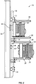
Figure 2 is a side view of an antenna interface in accordance with the first example.. -
Figure 3 is an end view of a remote radio head adapted for use in the first example of the present invention. -
Figure 4 is a side view of a remote radio head adapted for use in the first example of the present invention. -
Figure 5 is a perspective view of a remote radio head connector according to the present invention that is adapted for use in the first example of the present invention. -
Figure 6 is a perspective view of an antenna connector according to the present invention that is adapted for use in the first example of the present invention. -
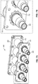
Figures 7a and 7b are perspective views illustrating certain details of connectors which may be used in connection with the first example of the present invention. -
Figure 8 is a perspective view of a diplexer connector adapted for use in the first example of the present invention. -
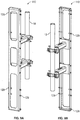
Figures 9a and 9b are perspective views of a second example of an antenna interface which may comprise one or more devices according to the present invention. -
Figures 10a and 10b are side views of the standard antenna interface of the second example. -
Figure 11 is a perspective view of a third example which may comprise one or more devices according to the present invention. -
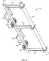
Figure 12 is a perspective view of a standard antenna interface according to the third example. -
Figure 13 is a perspective view of the third example with additional components. -
Figure 14 is a perspective view of the third example with additional components. -
Figures 15a-15c illustrate a combination of features from the second and third examples. -
Figures 16a-16b illustrate an antenna adapted for use in another example of the present invention. -
Figures 17a-17c illustrate a remote radio head adapted for use in another example of the present invention. -
Figure 18 is an exploded view of the RRH Connector illustrated inFigure 5 . -
Figure 19 is an exploded view of the RF Connector shown inFigure 6 . -
Figures 20 is a perspective view of an embodiment of a float gasket installed in an opening of a portion of a panel. -
Figure 21 is a cross section of an embodiment of a float gasket. -
Figures 22a-22b illustrate an embodiment of an adjustable mount assembly according to the present invention that is rear mounted to a remote radio head. -
Figure 23a-23b illustrate an embodiment of an adjustable mount assembly according to the present invention that is side mounted to a remote radio head. - A Standard Antenna Interface is described herein to overcome the limitations of a traditional RRH and antenna tower top installation. This disclosure creates a standard antenna interface that provides a reduced installation time, prevents the installer from directly touching/interfacing with the RF electrical path, creates a PIM free interface, and allows the network operator the flexibility to select any brand of antenna or RRH to install. This solution further enables the stocking of separate antennas and RRH's, thus reducing the cost of inventory. In addition, the higher failure rate RRH's can be replaced independently of the more reliable passive antennas.
- The Standard Antenna Interface comprises of a standard interface structure, including antenna mounting brackets and RRH mounting structure, and a RF interconnection module. The standard interface structure acts as the mounting medium for both the antenna and the RRH. Both the antenna and RRH are mounted to their respective universal mounting structure. One mounting structure will receive the antenna and, optionally, all necessary interconnects, where the other bracket or mounting structure will receive the RRH and, optionally necessary interconnects. In embodiments where the Standard Interface Structure does not include RF interconnects, such RF interconnects are made directly between the antenna and the RRH. Each entity will mount directly to the standard interface structure and can be removed independently from each other. Preferably, the Standard Antenna Interface allows antennas and radios from different manufacturers to be coupled together in the field without adding jumper cables and/or ohmic connections.
- Referring to
Figures 1 and2 , a first example of aStandard Antenna Interface 10 is disclosed. In this example, anUpper Tower Mount 12, andMiddle Tower Mount 14 and aLower Tower Mount 16 are mounted on aMounting Pole 18. TheUpper Tower Mount 12, andMiddle Tower Mount 14 and aLower Tower Mount 16 are configured to mechanically interface with a plurality ofRemote Radio Heads 20 and anAntenna 22. Preferably, theUpper Tower Mount 12, andMiddle Tower Mount 14 and aLower Tower Mount 16 are configured to mechanically interface with aDiplexer 24 placed between aRemote Radio Head 20 and theAntenna 22. - The example illustrated in Figures land 2 allows for the installation of up to four
Remote Radio Heads 20. In an alternative example (not illustrated), when one or twoRemote Radio Heads 20 are desired, theMiddle Tower Mount 14 may be omitted. - The
Upper Tower Mount 12 and theLower Tower Mount 16 each include a Linear GuidedSupport 26. In the illustrated example, the Linear GuidedSupports 26 comprise tracks that are configured to receive a roller trolley. However, alternative track and low friction car slide structures are within the scope of this disclosure and may be substituted. In this example, theUpper Tower Mount 12 includes an Antenna Mount 28. Anadditional Antenna Mount 29 is included on the MountingPole 18. TheAntenna 22 includes Brackets 30, which include slots to engage Antenna Mount 28 andAntenna Mount 29.Middle Tower Mount 14 includes two Linear Guided Supports 26. The Linear GuidedSupports 26 are on the opposite side of theMounting Pole 18 from theAntenna 22 and extend away from theAntenna 22. - Alternatively, the
Lower Tower Mount 16 may be structurally the same asUpper Tower Mount 12, but is inverted when mounted. TheUpper Tower Mount 12 and theLower Tower Mount 16 each include an Antenna Mount 28 in this example. - Referring to
Figure 3 and Figure 4 , theRemote Radio Head 20 includes an UpperLow Friction Car 32 and a LowerLow Friction Car 34. The UpperLow Friction Car 32 and a LowerLow Friction Car 34 each engage a respective Linear GuidedSupport 26. For example, when aRemote Radio Head 20 is installed in a lower location on the Standard Interface, the UpperLow Friction Car 32 engages a Linear GuidedSupport 26 of theMiddle Tower Mount 14 and the LowerLow Friction Car 34 engages the Linear GuidedSupport 26 of theLower Tower Mount 16. In the illustrated example, the UpperLow Friction Car 32 and the LowerLow Friction Car 34 each comprise a wheeled trolley. However, alternative low friction non-wheeled cars are also contemplated and may be substituted for the wheeled trolleys. - Each
Remote Radio Head 20 includes aRRH Connector 40. TheAntenna 20 includes a plurality of integratedRF Interconnection Modules 44 designed to engage a respectivemating RRH Connector 40. Alternatively, theRF Interconnection Module 44 may be located on theStandard Antenna Interface 10, and theAntenna 20 may be provided with a connector. - Once the Upper
Low Friction Car 32 and the LowerLow Friction Car 34 are engaged in their respective Linear GuidedSupports 26, theRemote Radio Head 20 may then slide into engagement withAntenna 22. Specifically, theRRH connector 40 is mated with its respectiveRF Interconnection Module 44. TheRemote Radio Head 20 may mate directly with the antenna, or optionally, aDiplexer 24 may be included between twoRemote Radio Heads 20 and theAntenna 22. TheRemote Radio Head 20 may be locked into place withLock 35. - When a
Diplexer 24 is used, theDiplexer 24 will include two sets ofRF Interconnection Modules 44 facing theRemote Radio Heads 20. TheDiplexer 24 also includes oneRRH Connector 40 facing theAntenna 22. TheAntenna 22 may be configured to have a singleRF Interconnection Module 44 facing theDiplexer 24. TheDiplexer 24 includes a pair of UpperLow Friction Cars 32 and a pair of LowerLow Friction Cars 34. In addition toRemote Radio Head 20 andDiplexer 24, additional types of tower-mountable equipment, such as filters, may be accommodated by theStandard Antenna Interface 10. - An assembly may comprise as few as one antenna and one
Remote Radio Head 20. However, as illustrated in the figures, each Linear GuidedSupport 26 may include two channels to accept twoRemote Radio Heads 20, and there may be more than one pair of Linear GuidedSupports 26 for eachAntenna 22. In the illustrated examples, there may be fourRemote Radio Heads 20 coupled to theAntenna 22. - The example of
Figures 1-4 enable straight-in, linear engagement of the RF connectors. This allows for an improved design of blind-matable, capacitively coupled RF connectors to be employed. An example of such a long-engagement is illustrated inFigures 5 and 6 . - As illustrated in
Figures 5 and 6 ,RF Interconnection Module 44 andRRH Connector 40 may comprise a blind mate connector of coaxial construction. In one example, theRF Interconnection Module 44 may include includes a central conductor extension having a generallyCylindrical Post 60 and anOuter Conductor Extension 62. TheCylindrical Post 60 may be covered by a dielectric layer, such as one formed of a polymeric shrink sleeve. TheRRH Connector 40 may include aCentral Conductor Extension 64 that is adapted to receive theCylindrical Post 60 of theRF Interconnection Module 44, and anOuter Conductor Extension 66 configured to fit within theOuter Conductor Extension 62. A dielectric layer overlies theOuter Conductor Extension 66. The dielectric layers prevent an ohmic connection between the conductor extensions and ensure that the coupling is capacitive, reducing the possibility of Passive Intermodulation (PIM). - The
RF Interconnection Module 44 may include a float plate to improve alignment of capacitive, blind mate connectors. Referring toFigures 7a and 7b , portions of anInterconnection Module 44 including aFloat Plate 70 are illustrated. Thefloat plate 70 may receive blind mated coaxial connectors within each opening; four such interconnections, designated at 72 illustrated inFigures 7a and 7b . Thefloat plate 70 is typically mounted to a rigid structure, such as a back of an antenna, that includes openings that align with the openings in thefloat plate 70. The openings in the rigid structure are sufficiently large that they do not interfere with flexure of thefingers 76 normal to themain body panel 78. Exemplary environments in which float plates may be employed with blind-matable connectors are discussed inU.S. Patent Publication No. 2013/0065415 to Van Swearingen et al. . - As can be understood with reference to
Figures 7a and 7b , as aconnector 80 is inserted into thefloat plate 70, thefingers 76 can flex to help to compensate for any misalignment of theconnector 80 relative to itsmating connector 82. Such misalignment is not uncommon due to minor tolerance differences in the sizes of theconnectors - While a rolling, straight-in engagement is advantageous, another example employs a pivoting, axially guided engagement. Referring to
Figures 9a, 9b ,10a and 10b , theStandard Antenna Interface 110 mounts away from the pole or the wall and houses theAntenna 122 andRemote Radio Head 120 on one side of the pole. In this example, theStandard Antenna Interface 110 is constructed out of formed sheet metal. However, theStandard Antenna Interface 110 may also be constructed out of metal rectangular tubing. As in the example above, anRF Interconnection Module 144 is integrated into Antenna 122 (Fig. 10a ). - Referring to
Figures 10a and 10b , a Remote Radio Head may be connected to theStandard Antenna Interface 110. TheRemote Radio Head 120 includes mounting ahooked Mounting Bracket 127 and a slottedMounting Bracket 128. TheStandard Antenna Interface 110 includesPins 129, which comprise axially guided support structure. The hookedMounting Bracket 127 and a slottedMounting Bracket 128 engage thePins 129 of the Standard Antenna Interface (Fig. 9a ), and allow theRemote Radio Head 120 to rotate into engagement (Fig. 9b ). In another example, TheStandard Antenna Interface 110 may be configured receive two or moreRemote Radio Heads 120. TheAntenna 122 also has a hooked Mounting Bracket 127 (not illustrated) and a slottedMounting Bracket 128 that engagesPins 129 and allowsAntenna 122 to be rotated into engagement in a similar manner. - The
Remote Radio Head 120 may be installed and/or removed from theStandard Antenna Interface 110 without moving the Antenna 122 (10a). Similarly, theAntenna 122 may be installed and/or removed from theStandard Antenna Interface 110 without moving the Remote Radio Head 120 (10b). In another example, the hookedMounting Bracket 127 and the slottedMounting Bracket 128 may be replaced with a single piece mounting bracket. The linear guided support structure and the axially guided support structure may also be used in combination. For example, an antenna may be mounted using the axially guided support structure, such asPins 129 and correspondingHooked Mounting Bracket 127, and tower mountable equipment may be installed using Linearly GuidedSupports 26 andLow Friction Cars - Referring to
Figures 11 and12 , a perspective view of an additional example is illustrated. In this example, theStandard Antenna Interface 210 accommodates anAntenna 222 and up to four RRHRemote Radio Heads 220. In this example, theStandard Antenna Interface 210 is mounted to a pole. TheStandard Antenna Interface 210 includesCross Members Vertical Member 217. - Referring to
Figure 12 , theStandard Antenna Interface 210 includes MountingPoints 228 for theAntenna 222 andRF Interconnection Modules 244. Referring toFigure 13 , anAntenna 222 mounted to theStandard Antenna Interface 210. MountingBrackets 229 for receivingRemote Radio Heads 120 are also installed on theStandard Antenna Interface 210 in an upper position.Float Plates 270 may be included on the MountingBrackets 229. Additionally, anoptional Diplexer 224 is mounted on theStandard Antenna Interface 210.Figure 14 continues the example ofFigure 13 , with the inclusion of MountingBrackets 229 being installed on theDiplexer 224. TheRemote Radio Heads 220 may be mounted on theDiplexer 224 in the same way that they would be mounted directly to theStandard Antenna Interface 210. The MountingBrackets 224 include anRF Interconnection Module 244, which interfaces with Antenna Connector 242 and connectors on the Remote Radio Head (not illustrated). - The installation of the
Diplexer 224 on the lower mounting brackets is just one example; aDiplexer 224 may be included on the upper mounting brackets, the lower mounting brackets, both mounting brackets, or omitted altogether. This flexibility in optionally including a diplexer is an advantage of this example. - The
RF Interconnection Module 244 comprises a blind mate RF connector system that provides 7/16 DIN type RF performance in a blind mate approach for fast and robust component interfacing. TheRF Interconnection Module 244 may include capacitively coupled interfaces and/or connectors such as those described inU.S. Patent Application Nos. 13/672,965 13/673,084 13/673,373 - Referring to
figure 15 , an example of aStandard Antenna Interface 310 including anRF Interconnection Module 344 is illustrated.RRH Connector 340 ofRemote Radio Head 320 engages one side of theRF Interconnection Module 344, andAntenna Connector 320 ofAntenna 322 engages the other side of theRF Interconnection Module 344. - Referring to
Figures 16a-16b and17a-17c , examples of anAntenna 422 and aRemote Radio Head 420 including RF Interconnection Module 444 andRRH Connector 440 are illustrated.Figure 16b illustratesRF jumper cables 452 connected from a bottom of anAntenna 422 to an RF interconnector module 444. Similarly,Figure 17c illustratesRF jumper cables 454 connected from anRRH 420 to aRRH Connector 440.Jumper cables RRH 420 orantenna 440 and capacitive connectors on the other hand for attachment to theRRH Connector 440 or RF Interconnection Module 444. In these examples, installation of the RF Interconnection Module 444 andRRH Connector 440 occurs prior to traveling to the deployment site so that the harness and alljumper cabling 452 and 454 (inFigures 16b and17c ) can be tested for RF path integrity and concealed behind acovers 450 and 456 (inFigures 16b ,17b and17c ). Such concealment prevents an installer from touching or otherwise interfacing with this RF path and may provide an aesthetically pleasing look. -
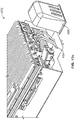
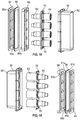
Figure 18 is an exploded view of theRRH Connector 40 illustrated inFigure 5 .Figure 19 is an exploded view of theRF Connector 44 shown inFigure 6 . TheRRH Connector 40 comprises aconnector housing 90,capacitive connectors 64, a float plate 70 (seeFigures 7a and 7b ), and a float assembly comprisingfloat shells float gasket 86. Thefloat gasket 86 may be an elastomeric material.Float shell 84 may include afirst flange 85a and asecond flange 85b (also shown inFigure 19 ) adapted to engagefloat shell 88. Similarly, floatshell 88 may include afirst flange 89a and asecond flange 89b (also shown inFigure 18 ) adapted to engagefloat shell 84. When assembled,flanges float gasket 86 in a space between thefloat shells float gasket 86. Thefloat plate 70 allows thecapacitive connectors 64 to move with respect to theconnector housing 90, such as by the flexure offingers 76 as described above with respect toFigures 7a and 7b . Thefloat gasket 86 allows theconnector housing 90 to move with respect to a surface on which theRF connector 40 is mounted, as described below with respect toFigures 20, 21 ,22a, 22b .23a and 23b . - Similarly, the
RF Connector 44 comprises aconnector housing 94,capacitive connectors 62, a float plate 70 (seeFigures 7a and 7b ), and a float assembly comprisingfloat shells float gasket 86. Again, thefloat plate 70 allows thecapacitive connectors 62 to move with respect to theconnector housing 94, and thefloat gasket 86 allows theconnector housing 90 to move with respect to a surface on which theRF connector 40 is mounted. Theconnector housings bevels housings capacitive connectors - Referring to
Figures 20 and 21 , one embodiment of afloat gasket 86 is illustrated in more detail.Figure 20 is a perspective view of afloat gasket 86 installed in an opening of a portion of a panel. Thefloat gasket 86 includes afirst flange portion 81a and asecond flange portion 81b (seeFigure 19 ) separated by amiddle portion 83.Figure 21 is a cross section of thefloat gasket 86 to illustrate afirst flange 81a andribs 87. First andsecond flanges float gasket 86 is to be installed. Themiddle portion 83 includes a plurality ofouter ribs 87. Theribs 87 extend outwardly from themiddle portion 83 and are dimensioned to engage an inner periphery of the hole in which thefloat gasket 86 is mounted. Thefloat gasket 86 and/orribs 87 may be compressed slightly, which allows the connector shell to "float" within the opening on the surface to which theRRH connector 40 orRF connector 44 is mounted. In practice, afloat gasket 86 is installed in an opening, floatshells float gasket 86, afloat plate 70 andcapacitive connectors connector housing -
Figures 22a, 22b ,23a and 23b illustrate an embodiment of anadjustable mount assembly 500 that may be side mounted or rear mounted to aRRH 20. InFigures 22a and 22b , themount assembly 500 is rear mounted to aRRH 20. Themount assembly 500 includes afirst bracket 502 and asecond bracket 504. Thefirst bracket 502 includes a first set ofadjustable slots slots mount assembly 500 to theRRH 20 and also serve to fix the relative positions ofbrackets brackets RRHs 40 of various size.Bracket 504 includes anopening 541 for receiving anRRH connector 40, such as the RRH connector shown inFigure 18 . TheRRH connector 40 may be cabled to theRRH 20 byjumper cables 544.Jumper cables 554 may include metal-to-metal ohmic connectors on the one hand for attachment to theRRH 20 and capacitive connectors on the other hand for attachment to theRRH Connector 40.Bracket 504 also may include an UpperLow Friction Car 32 and/or a LowerLow Friction Car 34 that operate as described above with respect toFigures 3 and 4 . -
Figures 23a and 23b show themount assembly 500 side mounted to aRRH 20. As illustrated, thefirst bracket 502 includes a second set ofadjustable slots mount posts Mount posts brackets assembly 500 is rear mounted to aRRH 20,mount posts brackets Brackets apertures assembly 500 to theRRH 20. WhileFigures 22a, 22b ,23a and 23b illustrate an embodiment of anadjustable mount assembly 500 that may be side mounted or rear mounted to aRRH 20,mount assembly 500 may be modified to provide only side mounting, only rear mounting, or other functionality contemplated herein. - In practice,
brackets jumper cables 554, and RRH Connector 40 (including, for example, floatgasket 86,float shells float plate 70,capacitive connectors 66, and/or connector housing 90) may be assembled/mounted to anRRH 20 and/or fully tested offsite, such as an in a factory setting. This enables all ohmic connections (metal-to-metal) to be done in a controlled environment such as a the factory and performance tested before shipping a completed assembly to the field. In the field, the only RF connections that need to be made are the capacitive, which are more reliable and less likely to induce PIM. - The present disclosure is not limited to remote radio heads and antennas. Universal mounting brackets may also be used to mount additional items of tower-mountable equipment.
- In another example, the standard interface structure mounts directly to the pole and allows the RRH and the antenna to straddle the pole. The standard interface structure includes an RF interconnection module, which is moved off to the side so it avoids the pole when the RRH and antenna are engaged. The RRH and Antenna mount directly to the standard interface structure, and each may be removed independently.
- In another example, instead of mounting to a pole, the Standard Antenna Interface may replace a pole in a tower installation. In this example, the structure may comprise rectangular tubing or round tubing with an extended pipe tubing at both ends. The RF interconnect mates inside the center structure and is concealed within the structure when the antenna and RRH are installed.
- In another example, additional functionality is added to the standard antenna interface by way of RF filtering and/or amplification. Additional modules, such as a tower mount amplifiers (TMA) or RF filters, may be added within the standard interface structure. These modules will contain an RF interconnection module on one or both sides, enabling it to directly connect to the antenna or RRH. The modules may be removable separate entities, or permanently embedded into the standard interface enclosure.
Claims (8)
- An RF interconnection module (40, 44) comprising:a connector housing (90, 94);a capacitive coupling (62, 64) at least partially disposed in the connector housing (90, 94);a float gasket (86) comprising a middle portion (83) and first and second flanges (81a, 81b), wherein the middle portion (83) is configured to engage with an inner periphery of an opening into which the float gasket (86) is to be installed, wherein the first and second flanges (81a, 81b) are dimensioned to be larger than the opening in which the float gasket (86) is to be installed, and wherein, when the connector housing (90, 94) is mounted, one of the first and second flanges (81a, 81b) of the float gasket (86) is positioned between the connector housing (90, 94) and a surface that includes the opening; anda first float shell (84) and a second float shell (88) each configured to engage a respective flange (81a, 81b) of the float gasket (86),wherein the float gasket (86) is configured to allow the connector housing (90, 94) to move with respect to the surface that includes the opening.
- The RF interconnection module (40, 44) of claim 1, wherein the middle portion (83) includes a plurality of outwardly extending ribs (87) for movably securing the float gasket (86) in the opening.
- The RF interconnection module (40, 44) of claim 1, further comprising:a float plate (70) disposed in the connector housing (90, 94),wherein the capacitive coupling (62, 64) is movably disposed in the float plate (70) so that the capacitive coupling (62, 64) may move with respect to the connector housing (90, 94).
- The RF interconnection module (40, 44) of claim 3, wherein the float plate (70) includes a plurality of flexible fingers (76) that define an aperture for receiving the capacitive coupling (62, 64), the flexible fingers (76) movably securing the capacitive coupling (62, 64) in the aperture.
- A mount assembly (500) comprising:a bracket assembly (502, 504) attachable to a tower-mounted equipment (20); andat least one jumper cable (544, 554) having at least one ohmic connector for connecting to the tower-mounted equipment (20) and at least one capacitive connector, whereinthe at least one capacitive connector comprises an RF interconnection module (40) according to claim 1, the RF interconnection module (40) being mounted on the bracket assembly (504).
- The mount assembly (500) of claim 5, wherein the float gasket (86) movably mounts the RF interconnection module (40) on the bracket assembly (504).
- The mount assembly (500) of claim 5, further comprising at least one diplexer (24) having a low friction car (32, 34) configured to engage a linear guided support member (26) of a radio head mount (20).
- The RF interconnection module (40, 44) of claim 1, wherein the first float shell (84) and the second float shell (88) each comprises a pair of flanges (85a, 85b, 89a, 89b) operable to secure the float gasket (86) in a space between the first float shell (84) and the second float shell (88).
Applications Claiming Priority (2)
| Application Number | Priority Date | Filing Date | Title |
|---|---|---|---|
| US201361863739P | 2013-08-08 | 2013-08-08 | |
| PCT/US2014/049971 WO2015026528A2 (en) | 2013-08-08 | 2014-08-06 | Standard antenna interface |
Publications (2)
| Publication Number | Publication Date |
|---|---|
| EP3031098A2 EP3031098A2 (en) | 2016-06-15 |
| EP3031098B1 true EP3031098B1 (en) | 2020-10-07 |
Family
ID=52484249
Family Applications (1)
| Application Number | Title | Priority Date | Filing Date |
|---|---|---|---|
| EP14758196.1A Not-in-force EP3031098B1 (en) | 2013-08-08 | 2014-08-06 | Standard antenna interface |
Country Status (3)
| Country | Link |
|---|---|
| EP (1) | EP3031098B1 (en) |
| CN (1) | CN104937773B (en) |
| WO (1) | WO2015026528A2 (en) |
Cited By (1)
| Publication number | Priority date | Publication date | Assignee | Title |
|---|---|---|---|---|
| WO2025193132A1 (en) * | 2024-03-13 | 2025-09-18 | Telefonaktiebolaget Lm Ericsson (Publ) | A connector assembly |
Families Citing this family (6)
| Publication number | Priority date | Publication date | Assignee | Title |
|---|---|---|---|---|
| DE102016116081A1 (en) * | 2016-08-29 | 2018-03-01 | Kathrein-Werke Kg | Holding and / or mounting frame, which is formed on or in a mobile radio antenna and / or on or in an electronic and / or filter module or fastened thereto, and an associated mobile radio antenna |
| WO2021034875A1 (en) | 2019-08-21 | 2021-02-25 | Commscope Technologies Llc | Jumper cable assembly |
| CN114830436B (en) * | 2019-12-18 | 2026-01-06 | 户外无线网络有限公司 | Base station antenna unit with an array of multiple antennas connected by jumper cables |
| CN212338839U (en) * | 2020-05-13 | 2021-01-12 | 中兴通讯股份有限公司 | Installation device and communication device |
| CN118679642A (en) * | 2022-01-13 | 2024-09-20 | 株式会社Kmw | Antenna device |
| US12609720B2 (en) * | 2022-11-01 | 2026-04-21 | Communication Components Antenna Inc. | Integrated remote radio head and antenna module assembly |
Family Cites Families (3)
| Publication number | Priority date | Publication date | Assignee | Title |
|---|---|---|---|---|
| US6126128A (en) * | 1998-11-20 | 2000-10-03 | Lucent Technologies Inc. | Adjustable mounting bracket |
| US20100079346A1 (en) * | 2008-09-30 | 2010-04-01 | Arc Wireless Solutions, Inc. | Universal enclosure system |
| WO2013071206A1 (en) * | 2011-11-11 | 2013-05-16 | Andrew Llc | Blind mate capacitively coupled connector |
-
2014
- 2014-08-06 WO PCT/US2014/049971 patent/WO2015026528A2/en not_active Ceased
- 2014-08-06 CN CN201480003600.1A patent/CN104937773B/en not_active Expired - Fee Related
- 2014-08-06 EP EP14758196.1A patent/EP3031098B1/en not_active Not-in-force
Non-Patent Citations (1)
| Title |
|---|
| None * |
Cited By (1)
| Publication number | Priority date | Publication date | Assignee | Title |
|---|---|---|---|---|
| WO2025193132A1 (en) * | 2024-03-13 | 2025-09-18 | Telefonaktiebolaget Lm Ericsson (Publ) | A connector assembly |
Also Published As
| Publication number | Publication date |
|---|---|
| WO2015026528A2 (en) | 2015-02-26 |
| WO2015026528A3 (en) | 2015-04-16 |
| EP3031098A2 (en) | 2016-06-15 |
| CN104937773B (en) | 2018-08-17 |
| CN104937773A (en) | 2015-09-23 |
Similar Documents
| Publication | Publication Date | Title |
|---|---|---|
| US9450351B2 (en) | Standard antenna interface | |
| US9172421B2 (en) | Standard antenna interface | |
| WO2016036951A1 (en) | Azimuth and elevation angle pole mounting system for wireless communications base sites | |
| WO2015026528A2 (en) | Standard antenna interface | |
| US10944155B2 (en) | Standard antenna interface connector assembly | |
| US11735875B2 (en) | Integrated antenna unit with blind mate interconnect | |
| US9692115B2 (en) | Antenna radome with removeably connected electronics module | |
| US7422486B2 (en) | Connectors to connect modules to electronic devices | |
| US7901236B2 (en) | Telecommunication patch panel | |
| US12101853B2 (en) | Base station antenna units having arrays spanning multiple antennas that are connected by jumper cables | |
| US8194409B2 (en) | Guide frame for a pluggable module | |
| US9692168B1 (en) | Header assembly | |
| US20180287250A1 (en) | Combination external vehicle antenna housing and installation method | |
| US8550859B2 (en) | Close proximity panel mount connectors | |
| US20170256866A1 (en) | Modular housing arrangement for antennae | |
| TWI657617B (en) | Modular antenna assemblies for wireless systems | |
| US11469537B2 (en) | Jumper cable assembly | |
| US20030036313A1 (en) | Plug connector with adapter | |
| US20130016475A1 (en) | Modular frequency based fiber transport and radio transport repeater platform for diverse radio frequency configurable deployments | |
| US20220224097A1 (en) | Cable-entry device for an electronic chassis | |
| WO2002063711A1 (en) | System and method of mounting protected microwave radios with a parabolic antenna | |
| AU2007216865B2 (en) | Connectors to connect modules to electronic devices |
Legal Events
| Date | Code | Title | Description |
|---|---|---|---|
| PUAI | Public reference made under article 153(3) epc to a published international application that has entered the european phase |
Free format text: ORIGINAL CODE: 0009012 |
|
| 17P | Request for examination filed |
Effective date: 20150716 |
|
| AK | Designated contracting states |
Kind code of ref document: A2 Designated state(s): AL AT BE BG CH CY CZ DE DK EE ES FI FR GB GR HR HU IE IS IT LI LT LU LV MC MK MT NL NO PL PT RO RS SE SI SK SM TR |
|
| AX | Request for extension of the european patent |
Extension state: BA ME |
|
| DAX | Request for extension of the european patent (deleted) | ||
| STAA | Information on the status of an ep patent application or granted ep patent |
Free format text: STATUS: EXAMINATION IS IN PROGRESS |
|
| 17Q | First examination report despatched |
Effective date: 20171129 |
|
| GRAP | Despatch of communication of intention to grant a patent |
Free format text: ORIGINAL CODE: EPIDOSNIGR1 |
|
| STAA | Information on the status of an ep patent application or granted ep patent |
Free format text: STATUS: GRANT OF PATENT IS INTENDED |
|
| INTG | Intention to grant announced |
Effective date: 20200423 |
|
| RIN1 | Information on inventor provided before grant (corrected) |
Inventor name: SCHMUTZLER, STEVEN LEE Inventor name: BONCZYK, MICHAEL F. Inventor name: BUTLER, RAY K. Inventor name: BUONDELMONTE, CHARLES J. Inventor name: KURK, MORGAN C. Inventor name: DICKERSON, CALVIN Inventor name: COLAPIETRO, JULIAN Inventor name: DONALDSON, JIMMY L. JR. |
|
| GRAS | Grant fee paid |
Free format text: ORIGINAL CODE: EPIDOSNIGR3 |
|
| GRAA | (expected) grant |
Free format text: ORIGINAL CODE: 0009210 |
|
| STAA | Information on the status of an ep patent application or granted ep patent |
Free format text: STATUS: THE PATENT HAS BEEN GRANTED |
|
| AK | Designated contracting states |
Kind code of ref document: B1 Designated state(s): AL AT BE BG CH CY CZ DE DK EE ES FI FR GB GR HR HU IE IS IT LI LT LU LV MC MK MT NL NO PL PT RO RS SE SI SK SM TR |
|
| REG | Reference to a national code |
Ref country code: GB Ref legal event code: FG4D |
|
| REG | Reference to a national code |
Ref country code: CH Ref legal event code: EP Ref country code: AT Ref legal event code: REF Ref document number: 1322141 Country of ref document: AT Kind code of ref document: T Effective date: 20201015 |
|
| REG | Reference to a national code |
Ref country code: DE Ref legal event code: R096 Ref document number: 602014071007 Country of ref document: DE |
|
| REG | Reference to a national code |
Ref country code: IE Ref legal event code: FG4D |
|
| REG | Reference to a national code |
Ref country code: FI Ref legal event code: FGE |
|
| REG | Reference to a national code |
Ref country code: SE Ref legal event code: TRGR |
|
| REG | Reference to a national code |
Ref country code: NL Ref legal event code: MP Effective date: 20201007 |
|
| REG | Reference to a national code |
Ref country code: AT Ref legal event code: MK05 Ref document number: 1322141 Country of ref document: AT Kind code of ref document: T Effective date: 20201007 |
|
| PG25 | Lapsed in a contracting state [announced via postgrant information from national office to epo] |
Ref country code: NL Free format text: LAPSE BECAUSE OF FAILURE TO SUBMIT A TRANSLATION OF THE DESCRIPTION OR TO PAY THE FEE WITHIN THE PRESCRIBED TIME-LIMIT Effective date: 20201007 Ref country code: PT Free format text: LAPSE BECAUSE OF FAILURE TO SUBMIT A TRANSLATION OF THE DESCRIPTION OR TO PAY THE FEE WITHIN THE PRESCRIBED TIME-LIMIT Effective date: 20210208 Ref country code: NO Free format text: LAPSE BECAUSE OF FAILURE TO SUBMIT A TRANSLATION OF THE DESCRIPTION OR TO PAY THE FEE WITHIN THE PRESCRIBED TIME-LIMIT Effective date: 20210107 Ref country code: RS Free format text: LAPSE BECAUSE OF FAILURE TO SUBMIT A TRANSLATION OF THE DESCRIPTION OR TO PAY THE FEE WITHIN THE PRESCRIBED TIME-LIMIT Effective date: 20201007 Ref country code: GR Free format text: LAPSE BECAUSE OF FAILURE TO SUBMIT A TRANSLATION OF THE DESCRIPTION OR TO PAY THE FEE WITHIN THE PRESCRIBED TIME-LIMIT Effective date: 20210108 |
|
| REG | Reference to a national code |
Ref country code: LT Ref legal event code: MG4D |
|
| PG25 | Lapsed in a contracting state [announced via postgrant information from national office to epo] |
Ref country code: AT Free format text: LAPSE BECAUSE OF FAILURE TO SUBMIT A TRANSLATION OF THE DESCRIPTION OR TO PAY THE FEE WITHIN THE PRESCRIBED TIME-LIMIT Effective date: 20201007 Ref country code: ES Free format text: LAPSE BECAUSE OF FAILURE TO SUBMIT A TRANSLATION OF THE DESCRIPTION OR TO PAY THE FEE WITHIN THE PRESCRIBED TIME-LIMIT Effective date: 20201007 Ref country code: BG Free format text: LAPSE BECAUSE OF FAILURE TO SUBMIT A TRANSLATION OF THE DESCRIPTION OR TO PAY THE FEE WITHIN THE PRESCRIBED TIME-LIMIT Effective date: 20210107 Ref country code: LV Free format text: LAPSE BECAUSE OF FAILURE TO SUBMIT A TRANSLATION OF THE DESCRIPTION OR TO PAY THE FEE WITHIN THE PRESCRIBED TIME-LIMIT Effective date: 20201007 Ref country code: PL Free format text: LAPSE BECAUSE OF FAILURE TO SUBMIT A TRANSLATION OF THE DESCRIPTION OR TO PAY THE FEE WITHIN THE PRESCRIBED TIME-LIMIT Effective date: 20201007 Ref country code: IS Free format text: LAPSE BECAUSE OF FAILURE TO SUBMIT A TRANSLATION OF THE DESCRIPTION OR TO PAY THE FEE WITHIN THE PRESCRIBED TIME-LIMIT Effective date: 20210207 |
|
| PG25 | Lapsed in a contracting state [announced via postgrant information from national office to epo] |
Ref country code: HR Free format text: LAPSE BECAUSE OF FAILURE TO SUBMIT A TRANSLATION OF THE DESCRIPTION OR TO PAY THE FEE WITHIN THE PRESCRIBED TIME-LIMIT Effective date: 20201007 |
|
| REG | Reference to a national code |
Ref country code: DE Ref legal event code: R097 Ref document number: 602014071007 Country of ref document: DE |
|
| PG25 | Lapsed in a contracting state [announced via postgrant information from national office to epo] |
Ref country code: LT Free format text: LAPSE BECAUSE OF FAILURE TO SUBMIT A TRANSLATION OF THE DESCRIPTION OR TO PAY THE FEE WITHIN THE PRESCRIBED TIME-LIMIT Effective date: 20201007 Ref country code: RO Free format text: LAPSE BECAUSE OF FAILURE TO SUBMIT A TRANSLATION OF THE DESCRIPTION OR TO PAY THE FEE WITHIN THE PRESCRIBED TIME-LIMIT Effective date: 20201007 Ref country code: SK Free format text: LAPSE BECAUSE OF FAILURE TO SUBMIT A TRANSLATION OF THE DESCRIPTION OR TO PAY THE FEE WITHIN THE PRESCRIBED TIME-LIMIT Effective date: 20201007 Ref country code: EE Free format text: LAPSE BECAUSE OF FAILURE TO SUBMIT A TRANSLATION OF THE DESCRIPTION OR TO PAY THE FEE WITHIN THE PRESCRIBED TIME-LIMIT Effective date: 20201007 Ref country code: CZ Free format text: LAPSE BECAUSE OF FAILURE TO SUBMIT A TRANSLATION OF THE DESCRIPTION OR TO PAY THE FEE WITHIN THE PRESCRIBED TIME-LIMIT Effective date: 20201007 Ref country code: SM Free format text: LAPSE BECAUSE OF FAILURE TO SUBMIT A TRANSLATION OF THE DESCRIPTION OR TO PAY THE FEE WITHIN THE PRESCRIBED TIME-LIMIT Effective date: 20201007 |
|
| PLBE | No opposition filed within time limit |
Free format text: ORIGINAL CODE: 0009261 |
|
| STAA | Information on the status of an ep patent application or granted ep patent |
Free format text: STATUS: NO OPPOSITION FILED WITHIN TIME LIMIT |
|
| PG25 | Lapsed in a contracting state [announced via postgrant information from national office to epo] |
Ref country code: DK Free format text: LAPSE BECAUSE OF FAILURE TO SUBMIT A TRANSLATION OF THE DESCRIPTION OR TO PAY THE FEE WITHIN THE PRESCRIBED TIME-LIMIT Effective date: 20201007 |
|
| 26N | No opposition filed |
Effective date: 20210708 |
|
| PG25 | Lapsed in a contracting state [announced via postgrant information from national office to epo] |
Ref country code: IT Free format text: LAPSE BECAUSE OF FAILURE TO SUBMIT A TRANSLATION OF THE DESCRIPTION OR TO PAY THE FEE WITHIN THE PRESCRIBED TIME-LIMIT Effective date: 20201007 Ref country code: AL Free format text: LAPSE BECAUSE OF FAILURE TO SUBMIT A TRANSLATION OF THE DESCRIPTION OR TO PAY THE FEE WITHIN THE PRESCRIBED TIME-LIMIT Effective date: 20201007 |
|
| PG25 | Lapsed in a contracting state [announced via postgrant information from national office to epo] |
Ref country code: SI Free format text: LAPSE BECAUSE OF FAILURE TO SUBMIT A TRANSLATION OF THE DESCRIPTION OR TO PAY THE FEE WITHIN THE PRESCRIBED TIME-LIMIT Effective date: 20201007 |
|
| REG | Reference to a national code |
Ref country code: CH Ref legal event code: PL |
|
| PG25 | Lapsed in a contracting state [announced via postgrant information from national office to epo] |
Ref country code: MC Free format text: LAPSE BECAUSE OF FAILURE TO SUBMIT A TRANSLATION OF THE DESCRIPTION OR TO PAY THE FEE WITHIN THE PRESCRIBED TIME-LIMIT Effective date: 20201007 |
|
| REG | Reference to a national code |
Ref country code: BE Ref legal event code: MM Effective date: 20210831 |
|
| PG25 | Lapsed in a contracting state [announced via postgrant information from national office to epo] |
Ref country code: LI Free format text: LAPSE BECAUSE OF NON-PAYMENT OF DUE FEES Effective date: 20210831 Ref country code: CH Free format text: LAPSE BECAUSE OF NON-PAYMENT OF DUE FEES Effective date: 20210831 |
|
| PG25 | Lapsed in a contracting state [announced via postgrant information from national office to epo] |
Ref country code: IS Free format text: LAPSE BECAUSE OF FAILURE TO SUBMIT A TRANSLATION OF THE DESCRIPTION OR TO PAY THE FEE WITHIN THE PRESCRIBED TIME-LIMIT Effective date: 20210207 Ref country code: LU Free format text: LAPSE BECAUSE OF NON-PAYMENT OF DUE FEES Effective date: 20210806 |
|
| PG25 | Lapsed in a contracting state [announced via postgrant information from national office to epo] |
Ref country code: IE Free format text: LAPSE BECAUSE OF NON-PAYMENT OF DUE FEES Effective date: 20210806 Ref country code: BE Free format text: LAPSE BECAUSE OF NON-PAYMENT OF DUE FEES Effective date: 20210831 |
|
| PG25 | Lapsed in a contracting state [announced via postgrant information from national office to epo] |
Ref country code: HU Free format text: LAPSE BECAUSE OF FAILURE TO SUBMIT A TRANSLATION OF THE DESCRIPTION OR TO PAY THE FEE WITHIN THE PRESCRIBED TIME-LIMIT; INVALID AB INITIO Effective date: 20140806 |
|
| PG25 | Lapsed in a contracting state [announced via postgrant information from national office to epo] |
Ref country code: CY Free format text: LAPSE BECAUSE OF FAILURE TO SUBMIT A TRANSLATION OF THE DESCRIPTION OR TO PAY THE FEE WITHIN THE PRESCRIBED TIME-LIMIT Effective date: 20201007 |
|
| P01 | Opt-out of the competence of the unified patent court (upc) registered |
Effective date: 20230530 |
|
| PGFP | Annual fee paid to national office [announced via postgrant information from national office to epo] |
Ref country code: GB Payment date: 20230828 Year of fee payment: 10 Ref country code: FI Payment date: 20230825 Year of fee payment: 10 |
|
| PGFP | Annual fee paid to national office [announced via postgrant information from national office to epo] |
Ref country code: SE Payment date: 20230827 Year of fee payment: 10 Ref country code: FR Payment date: 20230825 Year of fee payment: 10 Ref country code: DE Payment date: 20230829 Year of fee payment: 10 |
|
| PG25 | Lapsed in a contracting state [announced via postgrant information from national office to epo] |
Ref country code: MK Free format text: LAPSE BECAUSE OF FAILURE TO SUBMIT A TRANSLATION OF THE DESCRIPTION OR TO PAY THE FEE WITHIN THE PRESCRIBED TIME-LIMIT Effective date: 20201007 |
|
| PG25 | Lapsed in a contracting state [announced via postgrant information from national office to epo] |
Ref country code: MT Free format text: LAPSE BECAUSE OF FAILURE TO SUBMIT A TRANSLATION OF THE DESCRIPTION OR TO PAY THE FEE WITHIN THE PRESCRIBED TIME-LIMIT Effective date: 20201007 |
|
| REG | Reference to a national code |
Ref country code: DE Ref legal event code: R119 Ref document number: 602014071007 Country of ref document: DE |
|
| REG | Reference to a national code |
Ref country code: SE Ref legal event code: EUG |
|
| PG25 | Lapsed in a contracting state [announced via postgrant information from national office to epo] |
Ref country code: FI Free format text: LAPSE BECAUSE OF NON-PAYMENT OF DUE FEES Effective date: 20240806 |
|
| GBPC | Gb: european patent ceased through non-payment of renewal fee |
Effective date: 20240806 |
|
| PG25 | Lapsed in a contracting state [announced via postgrant information from national office to epo] |
Ref country code: DE Free format text: LAPSE BECAUSE OF NON-PAYMENT OF DUE FEES Effective date: 20250301 |
|
| PG25 | Lapsed in a contracting state [announced via postgrant information from national office to epo] |
Ref country code: GB Free format text: LAPSE BECAUSE OF NON-PAYMENT OF DUE FEES Effective date: 20240806 |
|
| PG25 | Lapsed in a contracting state [announced via postgrant information from national office to epo] |
Ref country code: FR Free format text: LAPSE BECAUSE OF NON-PAYMENT OF DUE FEES Effective date: 20240831 |
|
| PG25 | Lapsed in a contracting state [announced via postgrant information from national office to epo] |
Ref country code: SE Free format text: LAPSE BECAUSE OF NON-PAYMENT OF DUE FEES Effective date: 20240807 |
|
| PG25 | Lapsed in a contracting state [announced via postgrant information from national office to epo] |
Ref country code: TR Free format text: LAPSE BECAUSE OF FAILURE TO SUBMIT A TRANSLATION OF THE DESCRIPTION OR TO PAY THE FEE WITHIN THE PRESCRIBED TIME-LIMIT Effective date: 20201007 |