EP3030878B1 - Particle capture device - Google Patents
Particle capture device Download PDFInfo
- Publication number
- EP3030878B1 EP3030878B1 EP14745058.9A EP14745058A EP3030878B1 EP 3030878 B1 EP3030878 B1 EP 3030878B1 EP 14745058 A EP14745058 A EP 14745058A EP 3030878 B1 EP3030878 B1 EP 3030878B1
- Authority
- EP
- European Patent Office
- Prior art keywords
- particles
- particle
- capture device
- particle capture
- internal surface
- Prior art date
- Legal status (The legal status is an assumption and is not a legal conclusion. Google has not performed a legal analysis and makes no representation as to the accuracy of the status listed.)
- Active
Links
Images




Classifications
-
- G—PHYSICS
- G01—MEASURING; TESTING
- G01N—INVESTIGATING OR ANALYSING MATERIALS BY DETERMINING THEIR CHEMICAL OR PHYSICAL PROPERTIES
- G01N1/00—Sampling; Preparing specimens for investigation
- G01N1/28—Preparing specimens for investigation including physical details of (bio-)chemical methods covered elsewhere, e.g. G01N33/50, C12Q
- G01N1/44—Sample treatment involving radiation, e.g. heat
-
- G—PHYSICS
- G01—MEASURING; TESTING
- G01N—INVESTIGATING OR ANALYSING MATERIALS BY DETERMINING THEIR CHEMICAL OR PHYSICAL PROPERTIES
- G01N1/00—Sampling; Preparing specimens for investigation
- G01N1/02—Devices for withdrawing samples
- G01N1/22—Devices for withdrawing samples in the gaseous state
- G01N1/2202—Devices for withdrawing samples in the gaseous state involving separation of sample components during sampling
- G01N1/2208—Devices for withdrawing samples in the gaseous state involving separation of sample components during sampling with impactors
-
- G—PHYSICS
- G01—MEASURING; TESTING
- G01N—INVESTIGATING OR ANALYSING MATERIALS BY DETERMINING THEIR CHEMICAL OR PHYSICAL PROPERTIES
- G01N1/00—Sampling; Preparing specimens for investigation
- G01N1/28—Preparing specimens for investigation including physical details of (bio-)chemical methods covered elsewhere, e.g. G01N33/50, C12Q
-
- G—PHYSICS
- G01—MEASURING; TESTING
- G01N—INVESTIGATING OR ANALYSING MATERIALS BY DETERMINING THEIR CHEMICAL OR PHYSICAL PROPERTIES
- G01N15/00—Investigating characteristics of particles; Investigating permeability, pore-volume or surface-area of porous materials
- G01N15/02—Investigating particle size or size distribution
- G01N15/0255—Investigating particle size or size distribution with mechanical, e.g. inertial, classification, and investigation of sorted collections
-
- G—PHYSICS
- G01—MEASURING; TESTING
- G01N—INVESTIGATING OR ANALYSING MATERIALS BY DETERMINING THEIR CHEMICAL OR PHYSICAL PROPERTIES
- G01N15/00—Investigating characteristics of particles; Investigating permeability, pore-volume or surface-area of porous materials
- G01N15/02—Investigating particle size or size distribution
- G01N15/0266—Investigating particle size or size distribution with electrical classification
-
- G—PHYSICS
- G01—MEASURING; TESTING
- G01N—INVESTIGATING OR ANALYSING MATERIALS BY DETERMINING THEIR CHEMICAL OR PHYSICAL PROPERTIES
- G01N15/00—Investigating characteristics of particles; Investigating permeability, pore-volume or surface-area of porous materials
- G01N15/10—Investigating individual particles
- G01N15/1031—Investigating individual particles by measuring electrical or magnetic effects
-
- G—PHYSICS
- G01—MEASURING; TESTING
- G01N—INVESTIGATING OR ANALYSING MATERIALS BY DETERMINING THEIR CHEMICAL OR PHYSICAL PROPERTIES
- G01N15/00—Investigating characteristics of particles; Investigating permeability, pore-volume or surface-area of porous materials
- G01N2015/0038—Investigating nanoparticles
-
- G—PHYSICS
- G01—MEASURING; TESTING
- G01N—INVESTIGATING OR ANALYSING MATERIALS BY DETERMINING THEIR CHEMICAL OR PHYSICAL PROPERTIES
- G01N15/00—Investigating characteristics of particles; Investigating permeability, pore-volume or surface-area of porous materials
- G01N2015/0042—Investigating dispersion of solids
- G01N2015/0046—Investigating dispersion of solids in gas, e.g. smoke
-
- G—PHYSICS
- G01—MEASURING; TESTING
- G01N—INVESTIGATING OR ANALYSING MATERIALS BY DETERMINING THEIR CHEMICAL OR PHYSICAL PROPERTIES
- G01N15/00—Investigating characteristics of particles; Investigating permeability, pore-volume or surface-area of porous materials
- G01N15/10—Investigating individual particles
- G01N2015/1021—Measuring mass of individual particles
Definitions
- the present disclosure relates generally to aerosol analyzers and other particle measuring instruments, and more specifically to a particle capture device usable in aerosol analyzers and other particle measuring instruments.
- Fine atmospheric aerosols resulting from internal combustion engines, fossil fuel fired power plants, painting/stripping faculties, gas discharge boiler operations and other anthropogenic and biogenic sources, are known to have a serious impact on climate and human health.
- These aerosols are comprised of micron and sub micron sized particles, having various size distributions and chemical compositions. Such particles can influence climate directly by scattering or absorbing sunlight, and indirectly by altering cloud coverage. Further, such particles can contribute to health problems such as asthma, lung cancer, cardiovascular disease, respiratory disease, and other conditions. Given their impact on climate and human health, fine atmospheric aerosols composed of micron and sub micron sized particles are the subject to widespread study and monitoring.
- a variety of different types of aerosol analyzers and other particle measuring instruments have been developed to determine particle size distributions and chemical compositions of fine atmospheric aerosols.
- a focused particle beam is generated and directed towards a generally flat collection surface. The particles impact the collection surface, and a portion of them are retained. The retained particles are vaporized, and the resulting gaseous molecules are provided to a detector that produces results.
- White such an instrument may provide valuable information, typical designs have shortcomings.
- particle bounce is a complex phenomenon. A wide variety of factors, including size, chemical composition, phase (e.g., liquid or solid), impact velocity, and the like, may be in play. Given the complexities, modifying particle or impact surface properties to reduce particle bounce is challenging.
- particle collection efficiency in aerosol analyzers and other particle measuring instruments is improved by a particle capture device that employs multiple collisions to decrease momentum of particles until the particles are collected (e.g., vaporized or come to rest).
- the particle collection device includes an aperture through which a focused particle beam enters.
- a collection enclosure is coupled to the aperture and has one or more internal surfaces against which particles of the focused beam collide.
- One or more features are employed with the internal surfaces to promote particles to collide multiple times within the enclosure, and thereby be vaporized or come to rest, rather than escape through the aperture.
- a ratio of an internal collision area of the collection enclosure to an entrance area of the aperture may be maximized.
- a surface area of the internal surfaces of the collection enclosure defines the internal collision area.
- Boundaries of the aperture define the entrance area.
- the ratio should be greater than 1:1, and preferable should be greater than 20:1. In one implementation, the ratio is approximately 37:1.
- the ratio may be maximized by utilizing a special geometry for the internal surfaces of the collection enclosure.
- the ratio may also be maximized by altering surface properties of the internal surfaces of the collection enclosure. Further, a combination of the two approaches may be employed.
- an example aerosol analyzer 100 may include three main sections: an aerosol sampling chamber 110, a particle sizing chamber 120, and a particle composition detection chamber 130.
- the aerosol sampling chamber 110 draws in particle-laden gas (e.g., atmospheric air) having micron and/or sub-micron particles, and produces a focused particle beam 115.
- the aerosol sampling chamber 110 includes a series of orifice lenses under the pull of a vacuum system. The lenses serve to focus particles and to control supersonic gas expansion and particle acceleration, to form the focused particle beam 115.
- the focused particle beam 115 is passed to the particle sizing chamber 120. In the particle sizing chamber, particles are separated according to their size dependant velocity profile resulting from expansion into vacuum..
- the particle sizing chamber 120 includes a particle charging unit (not shown) that applies an electric charge to the particles, and a deflection section (not shown) where an electric field deflects the particles.
- the degree of deflection is related to particle size (size dependant velocity, size dependant charge and applied voltage). Particles within a narrow range of sizes are caused to pass through an off-axis slit and leave the particle sizing chamber and pass into the particle composition detection chamber 130.
- the particle sizing chamber 120 includes a beam chopper (not shown) that alternately blocks and passes the focused particle beam 115 to produce a succession of beam pulses. Particles undergo velocity dispersion where the velocities are inversely related to particle size. Accordingly, as each beam pulse travels, it spreads in the direction of travel, with smaller particles arriving before larger particles. Particles of sorted sizes are thereby be delivered to the particle composition detection chamber 130.
- the particle detection chamber 130 includes a particle capture device 140 and a detector 150.
- the focused particle beam enters the particle capture device 140 through an aperture 160.
- the focused particle beam 115 is then received into a collection enclosure 170 coupled to the aperture 160.
- a temperature change element 180 of the particle capture device 140 is arranged to heat and/or cool the collection enclosure 170, depending an the implementation.
- the temperature change element 180 may include a resistive heating element, a thermo eclectic cooling element (e.g., a Peltier cooler), a heating or cooling system that circulates hot or cold liquid through a closed loop circulation system, an irradiation heating source, such as a CO 2 laser, or another type of element that is capable of changing the temperature of the enclosure 170.
- Particles are substantially retained in the collection enclosure 170 of the particle capture device 140 until they are vaporized (e.g., as a result of heat from the temperature change element 180), or come to rest (e.g., for later vaporization in a controlled heating cycle).
- the particle capture device 140 may operate as a particle capture vaporizer or as a particle capture collector, depending on the implementation.
- the temperature change element 180 may continuously heat the collection enclosure 170 to vaporize collected particles substantially immediately (i.e., as soon as possible).
- the temperature change element 180 may perform controlled heating cycles, with periods of heat interspersed by periods of relative cool. Entering particles may encounter an initially cool collection enclosure 170, such that collected particles are not immediately vaporized. The collected particles may later be subjected to heating and be vaporized.
- the heating cycle may be precisely controlled to allow particle volatility to be studied providing further information on particle composition.
- Vaporized particles 190 are passed to the detector 150, which may be a mass spectrometer.
- the vaporized particles pass to the detector through the same aperture 160 that the focused particle beam originally entered. That is, the vaporized particles 190 exit the particle capture device 140 along the same axis upon which they entered as a focused particle beam 115.
- the aperture 160 is located within a detection region of the detector 150. In an implementation where the detector 150 includes a mass spectrometer, the aperture is within an ion formation chamber of the mass spectrometer.
- the collection enclosure 170 of the particle capture device 140 includes several internal surfaces upon which the particles collide multiple times. A surface area of the internal surfaces defines an internal collision area. Boundaries of the aperture 160 of the particle capture device 140 define an entrance area.
- a ratio of the internal collision area to the entrance area (referred to herein as the "capture efficiency ratio") is maximized within practical constraints.
- the capture efficiency ratio should be greater than 1:1, and preferable should be greater than 20:1. In one implementation, the capture efficiency ratio is approximately 37:1.
- the capture efficiency ratio may be increased somewhat by reducing the entrance area.
- the minimum size of the aperture 160 may be defined by the width of the focused particle beam to allow full entrance thereof.
- the capture efficiency ratio may be increased more significantly by maximizing the internal collision area.
- the internal collision area may be maximized through geometry of the internal surfaces of the collection enclosure 170 and/or through surface properties of the internal surfaces of the collection enclosure 170. Geometry may be used where specular reflections dominate. With substantially smooth internal surfaces, particles may bounce in a relatively predictable manner through specular reflection. Geometry of the internal surfaces can increase specular reflections, such that particles repeatedly collide with the internal surfaces until they are vaporized or come to rest.
- the particle capture device 140 has a generally cylindrical configuration, and is largely symmetrical about its major axis J-J.
- a front portion 210 of the particle capture device 140 includes the aperture 160 and the collection enclosure 170.
- the front portion 210 may be constructed from a solid piece of material, for example, a refractory metal such as Molybdenum or Tungsten.
- a heater body portion 220 of the particle capture device 140 functions as the temperature change element, in this case, providing resistive heating as current is applied to wires 240.
- the heater body portion 220 may be constructed from a solid piece of material also, for example, Molybdenum or Tungsten.
- a thermal support portion 230 of the particle capture device 140 is a thin walled tube connected to the heater body 220 and encloses part of the wires 240.
- the particle capture device 140 may function as a particle capture vaporizer or as a particle capture collector, as discussed above.
- An embedded thermocouple (not shown) inside heater body 220 or at the front of heater body 220 allows for temperature measurement.
- a focused particle beam may enter the aperture 160 and be received into the collection enclosure 170.
- the collection enclosure 170 includes several substantially smooth internal surfaces 250, 260, 270 upon which the particles of the focused particle beam collide, and a portion thereof bounce (e.g., rebound).
- the internal surfaces 250, 260, 270 are arranged to promote multiple collisions and minimize the possibility of particles escaping through the aperture 160, before the particles are vaporized or come to rest, as the case may be.
- the geometry may serve to substantially equally distribute the particles to all points on the internal surfaces 250, 260, 270, in a manner similar to an integrating sphere in the field of optics, which distributes light over all angles.
- a first internal surface 250 is positioned to receive the initial collision of the particles.
- the first internal surface 250 is oriented at an acute angle to the major axis J-J of the particle capture device 140 (and thereby at an acute angle to the trajectory of the focused particle beam), such that initial collisions (assuming spectral reflection) reduce momentum of the particles, but preserve the direction of the forward velocity vector components of the particles. That is, the orientation causes the particles to bounce (assuming spectral reflection) further into the collection enclosure 170 rather than towards that aperture 160.
- the angle between the major axis J-J (and the particle beam trajectory) and the first internal surface 250 is less than 30°. A shallower angle may lead to a more efficient but larger particle capture device 140.
- the angle between the major axis J-J (and the particle beam trajectory) and the first surface 250 is 16°.
- the first surface 250 may have a substantially conical shape, with a vertex angle of 16°.
- the second internal surface 260 is oriented at an acute angle to the first internal surface 250 and is configured to receive the next collision (assuming spectral reflection). The orientation again causes the particles to bounce (assuming spectral reflection) further into the collection enclosure 170 rather than towards that aperture 160.
- the second internal surface 260 is parallel to the major axis J-J such that an angle between the second internal surface 260 and the first internal surface is again 16°.
- the second internal surface 260 may have a substantially cylindrical shape.
- Particles may repeatedly bounce between the first internal surface 250 and the second internal surface 260 and may eventually encounter the third internal surface 270.
- the third internal surface 270 is oriented at an acute angle with respect to the second internal surface 260, and is configured to retain particles that are moving in a direction towards the aperture 160. In one implementation, an angle between the second internal surface 260 and the third internal surface is 270 is 14°.
- the third internal surface 270 may be shaped sustainably as a conical frustum, with the aperture 160 at its apex.
- spectral reflection is an idealized case, and even with substantially smooth surfaces, particles exhibit some variation in how they rebound.
- the example geometry of the example particle capture device 140 may minimize the number of particles that escape despite this variation. Referring to the ray trace model 600 of a single particle trajectory 610 shown in Fig. 6 , it can be seen that a particle is likely to undergo multiple collisions after it enters the collection enclosure 170, and finally be vaporized or come to rest.
- surface properties of one or more internal surfaces of the collection enclosure 170 may be used to promote multiple collisions.
- colliding particles may undergo more random reflections such that diffuse reflections dominate.
- Surface roughness may be introduced by adding wires entanglements (e.g., wire "birds nests"), constructing the surfaces from porous materials (e.g., which provide nooks and crevices), adding micro-scaled or nano-scaled grids produced from nano-technology processes or etching processes, or some other means of adding surface roughness.
- Surface roughness and the diffuse reflections resulting therefrom may be used together with special geometry to improve particle collection efficiency. However, diffuse reflections may also limit particle collection efficiency, and proved unwanted, in some cases.
- the particle device 140 may be used in an example aerosol analyzer 100 designed to measure fine atmospheric aerosols, it should be understood such the device 140 may also be used in a variety of other types of instruments, including other particle measuring instruments that measure particles from non-atmospheric sources. Such particle measuring instruments may lack some of the capabilities of the example aerosol analyzer 100, for instance the ability to produce results as function of particle size, and may have additional capabilities beyond those of the example aerosol analyzer 100.
- the particle capture device 140 and, specifically the collection enclosure 170 may be constructed from a variety of different materials, and be formed in a variety of different shapes suited for the goals discussed herein, within the scope of appended claims. In general, it should be understood that the above descriptions are meant to be taken only by way of example.
Landscapes
- Chemical & Material Sciences (AREA)
- Health & Medical Sciences (AREA)
- Life Sciences & Earth Sciences (AREA)
- Biochemistry (AREA)
- Physics & Mathematics (AREA)
- Analytical Chemistry (AREA)
- General Health & Medical Sciences (AREA)
- General Physics & Mathematics (AREA)
- Immunology (AREA)
- Pathology (AREA)
- Dispersion Chemistry (AREA)
- Engineering & Computer Science (AREA)
- Biomedical Technology (AREA)
- Molecular Biology (AREA)
- Sampling And Sample Adjustment (AREA)
Description
- The present disclosure relates generally to aerosol analyzers and other particle measuring instruments, and more specifically to a particle capture device usable in aerosol analyzers and other particle measuring instruments.
- Fine atmospheric aerosols resulting from internal combustion engines, fossil fuel fired power plants, painting/stripping faculties, gas discharge boiler operations and other anthropogenic and biogenic sources, are known to have a serious impact on climate and human health. These aerosols are comprised of micron and sub micron sized particles, having various size distributions and chemical compositions. Such particles can influence climate directly by scattering or absorbing sunlight, and indirectly by altering cloud coverage. Further, such particles can contribute to health problems such as asthma, lung cancer, cardiovascular disease, respiratory disease, and other conditions. Given their impact on climate and human health, fine atmospheric aerosols composed of micron and sub micron sized particles are the subject to widespread study and monitoring.
- A variety of different types of aerosol analyzers and other particle measuring instruments have been developed to determine particle size distributions and chemical compositions of fine atmospheric aerosols. In one type of instrument, a focused particle beam is generated and directed towards a generally flat collection surface. The particles impact the collection surface, and a portion of them are retained. The retained particles are vaporized, and the resulting gaseous molecules are provided to a detector that produces results. White such an instrument may provide valuable information, typical designs have shortcomings.
- One shortcoming of typical designs is that they have low particle collection efficiency. A significant percentage of particles impacting the collection surface may simply bounce off (i.e. impact and rebound), and be lost rather than vaporized and analyzed. Low particle collection efficiency may limit the overall performance of the instrument. White attempts have been made to increase particle collection efficiency, such attempts have had mixed results.
- Some attempts have focused on changing particle properties to reduce particle bounce. Modifications are made to the particles before they impact the collection surface. Other attempts have focused on modifying the impact surface, such as using greased plate impactors. However, particle bounce is a complex phenomenon. A wide variety of factors, including size, chemical composition, phase (e.g., liquid or solid), impact velocity, and the like, may be in play. Given the complexities, modifying particle or impact surface properties to reduce particle bounce is challenging.
- Other attempts have focused on applying corrections to compensate for low particle collection efficiency. Empirically determined correction factors may be applied to results to compensate for losses of mass or losses of concentration resulting from particle bounce. However, determining the appropriate correction factors may be challenging. Further, correction factors merely mask, and do not address, the underlying problem of low particle collection efficiency.
US 2012/255375 A1 discloses a particle capturing device that includes a needle like collision structure. Other particle capturing devices are disclosed inUS 2013/011930 A1 ,US 4968885 A ,DE 3938194 A1 andUS 2004/025604 A1 . - Accordingly, there is a need for improved techniques that may be used to, among other things, improve particle collection efficiency in aerosol analyzers and other particle measuring instruments.
- The device according to the present invention is defined by claim 1. The method according to the present invention is defined by claim 12. Further preferred aspects are defined by the dependent claims. In example embodiments, particle collection efficiency in aerosol analyzers and other particle measuring instruments is improved by a particle capture device that employs multiple collisions to decrease momentum of particles until the particles are collected (e.g., vaporized or come to rest). The particle collection device includes an aperture through which a focused particle beam enters. A collection enclosure is coupled to the aperture and has one or more internal surfaces against which particles of the focused beam collide. One or more features are employed with the internal surfaces to promote particles to collide multiple times within the enclosure, and thereby be vaporized or come to rest, rather than escape through the aperture.
- To promote multiple collisions, a ratio of an internal collision area of the collection enclosure to an entrance area of the aperture may be maximized. A surface area of the internal surfaces of the collection enclosure defines the internal collision area. Boundaries of the aperture define the entrance area. The ratio should be greater than 1:1, and preferable should be greater than 20:1. In one implementation, the ratio is approximately 37:1. The ratio may be maximized by utilizing a special geometry for the internal surfaces of the collection enclosure. The ratio may also be maximized by altering surface properties of the internal surfaces of the collection enclosure. Further, a combination of the two approaches may be employed.
- The description below refers to the accompanying drawings of example embodiments, of which:
-
Fig. 1 is a schematic diagram of an example aerosol analyzer in which an example particle capture device may be employed; -
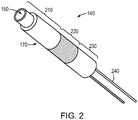
Fig. 2 is a perspective view of an example particle capture device that utilizes geometry to promote multiple collisions; -
Fig. 3 is a first cross section of the example particle capture device ofFig. 2 ; -
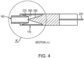
Fig. 4 is a second cross section of the example particle capture device ofFigs. 2 and3 , taken along major axis J-J inFig. 3 ; -
Fig. 5 is an enlarged cross section of the example particle capture device ofFigs. 2-4 , showing detail of region K inFig. 4 ; and -
Fig. 6 is a ray trace model of an example single particle trajectory in the example particle capture device ofFigs. 2-5 . - Referring to
Fig. 1 , anexample aerosol analyzer 100 may include three main sections: anaerosol sampling chamber 110, aparticle sizing chamber 120, and a particlecomposition detection chamber 130. Theaerosol sampling chamber 110 draws in particle-laden gas (e.g., atmospheric air) having micron and/or sub-micron particles, and produces a focusedparticle beam 115. In one implementation, theaerosol sampling chamber 110 includes a series of orifice lenses under the pull of a vacuum system. The lenses serve to focus particles and to control supersonic gas expansion and particle acceleration, to form the focusedparticle beam 115. Thefocused particle beam 115 is passed to theparticle sizing chamber 120. In the particle sizing chamber, particles are separated according to their size dependant velocity profile resulting from expansion into vacuum.. In one configuration, theparticle sizing chamber 120 includes a particle charging unit (not shown) that applies an electric charge to the particles, and a deflection section (not shown) where an electric field deflects the particles. The degree of deflection is related to particle size (size dependant velocity, size dependant charge and applied voltage). Particles within a narrow range of sizes are caused to pass through an off-axis slit and leave the particle sizing chamber and pass into the particlecomposition detection chamber 130. In another configuration, theparticle sizing chamber 120 includes a beam chopper (not shown) that alternately blocks and passes thefocused particle beam 115 to produce a succession of beam pulses. Particles undergo velocity dispersion where the velocities are inversely related to particle size. Accordingly, as each beam pulse travels, it spreads in the direction of travel, with smaller particles arriving before larger particles. Particles of sorted sizes are thereby be delivered to the particlecomposition detection chamber 130. - The
particle detection chamber 130 includes aparticle capture device 140 and adetector 150. The focused particle beam enters theparticle capture device 140 through anaperture 160. Thefocused particle beam 115 is then received into acollection enclosure 170 coupled to theaperture 160. Atemperature change element 180 of theparticle capture device 140 is arranged to heat and/or cool thecollection enclosure 170, depending an the implementation. Thetemperature change element 180 may include a resistive heating element, a thermo eclectic cooling element (e.g., a Peltier cooler), a heating or cooling system that circulates hot or cold liquid through a closed loop circulation system, an irradiation heating source, such as a CO2 laser, or another type of element that is capable of changing the temperature of theenclosure 170. - Particles are substantially retained in the
collection enclosure 170 of theparticle capture device 140 until they are vaporized (e.g., as a result of heat from the temperature change element 180), or come to rest (e.g., for later vaporization in a controlled heating cycle). In general, theparticle capture device 140 may operate as a particle capture vaporizer or as a particle capture collector, depending on the implementation. In an implementation where theparticle capture device 140 operates as a particle capture vaporizer, thetemperature change element 180 may continuously heat thecollection enclosure 170 to vaporize collected particles substantially immediately (i.e., as soon as possible). In an implementation where theparticle capture device 140 operates as a particle capture collector, thetemperature change element 180 may perform controlled heating cycles, with periods of heat interspersed by periods of relative cool. Entering particles may encounter an initiallycool collection enclosure 170, such that collected particles are not immediately vaporized. The collected particles may later be subjected to heating and be vaporized. The heating cycle may be precisely controlled to allow particle volatility to be studied providing further information on particle composition. -
Vaporized particles 190 are passed to thedetector 150, which may be a mass spectrometer. In one implementation, the vaporized particles pass to the detector through thesame aperture 160 that the focused particle beam originally entered. That is, the vaporizedparticles 190 exit theparticle capture device 140 along the same axis upon which they entered as afocused particle beam 115. Theaperture 160 is located within a detection region of thedetector 150. In an implementation where thedetector 150 includes a mass spectrometer, the aperture is within an ion formation chamber of the mass spectrometer. - As discussed above, previous collection surfaces have suffered from low particle collection efficiency. A significant percentage of particle simply bounce off the collection surfaces to be lost, such that they are not vaporized or collected for later vaporization. Rather than attempt to eliminate particle bounce, the
particle capture device 140 assumes particles will bounce, and employs multiple collisions to decrease the momentum of particles until they are collected (e.g., vaporized or come to rest). Thecollection enclosure 170 of theparticle capture device 140 includes several internal surfaces upon which the particles collide multiple times. A surface area of the internal surfaces defines an internal collision area. Boundaries of theaperture 160 of theparticle capture device 140 define an entrance area. To provide for particles to be collected, rather than lost, a ratio of the internal collision area to the entrance area (referred to herein as the "capture efficiency ratio") is maximized within practical constraints. The capture efficiency ratio should be greater than 1:1, and preferable should be greater than 20:1. In one implementation, the capture efficiency ratio is approximately 37:1. - The capture efficiency ratio may be increased somewhat by reducing the entrance area. The minimum size of the
aperture 160 may be defined by the width of the focused particle beam to allow full entrance thereof. The capture efficiency ratio may be increased more significantly by maximizing the internal collision area. The internal collision area may be maximized through geometry of the internal surfaces of thecollection enclosure 170 and/or through surface properties of the internal surfaces of thecollection enclosure 170. Geometry may be used where specular reflections dominate. With substantially smooth internal surfaces, particles may bounce in a relatively predictable manner through specular reflection. Geometry of the internal surfaces can increase specular reflections, such that particles repeatedly collide with the internal surfaces until they are vaporized or come to rest. - Referring to the
Figs. 2-5 , an example geometry is shown that promotes multiple collisions. In this example, theparticle capture device 140 has a generally cylindrical configuration, and is largely symmetrical about its major axis J-J. Afront portion 210 of theparticle capture device 140 includes theaperture 160 and thecollection enclosure 170. Thefront portion 210 may be constructed from a solid piece of material, for example, a refractory metal such as Molybdenum or Tungsten. Aheater body portion 220 of theparticle capture device 140 functions as the temperature change element, in this case, providing resistive heating as current is applied towires 240. Theheater body portion 220 may be constructed from a solid piece of material also, for example, Molybdenum or Tungsten. Athermal support portion 230 of theparticle capture device 140 is a thin walled tube connected to theheater body 220 and encloses part of thewires 240. By applying either continuous or cyclic heating, theparticle capture device 140 may function as a particle capture vaporizer or as a particle capture collector, as discussed above. An embedded thermocouple (not shown) insideheater body 220 or at the front ofheater body 220 allows for temperature measurement. - A focused particle beam may enter the
aperture 160 and be received into thecollection enclosure 170. Thecollection enclosure 170, as shown inFigs. 3-5 , includes several substantially smoothinternal surfaces internal surfaces aperture 160, before the particles are vaporized or come to rest, as the case may be. The geometry may serve to substantially equally distribute the particles to all points on theinternal surfaces - A first
internal surface 250 is positioned to receive the initial collision of the particles. The firstinternal surface 250 is oriented at an acute angle to the major axis J-J of the particle capture device 140 (and thereby at an acute angle to the trajectory of the focused particle beam), such that initial collisions (assuming spectral reflection) reduce momentum of the particles, but preserve the direction of the forward velocity vector components of the particles. That is, the orientation causes the particles to bounce (assuming spectral reflection) further into thecollection enclosure 170 rather than towards thataperture 160. Preferably the angle between the major axis J-J (and the particle beam trajectory) and the firstinternal surface 250 is less than 30°. A shallower angle may lead to a more efficient but largerparticle capture device 140. In one implementation, the angle between the major axis J-J (and the particle beam trajectory) and thefirst surface 250 is 16°. Thefirst surface 250 may have a substantially conical shape, with a vertex angle of 16°. - The second
internal surface 260 is oriented at an acute angle to the firstinternal surface 250 and is configured to receive the next collision (assuming spectral reflection). The orientation again causes the particles to bounce (assuming spectral reflection) further into thecollection enclosure 170 rather than towards thataperture 160. In one implementation, the secondinternal surface 260 is parallel to the major axis J-J such that an angle between the secondinternal surface 260 and the first internal surface is again 16°. The secondinternal surface 260 may have a substantially cylindrical shape. - Particles may repeatedly bounce between the first
internal surface 250 and the secondinternal surface 260 and may eventually encounter the thirdinternal surface 270. The thirdinternal surface 270 is oriented at an acute angle with respect to the secondinternal surface 260, and is configured to retain particles that are moving in a direction towards theaperture 160. In one implementation, an angle between the secondinternal surface 260 and the third internal surface is 270 is 14°. The thirdinternal surface 270 may be shaped sustainably as a conical frustum, with theaperture 160 at its apex. - It should be understood that spectral reflection is an idealized case, and even with substantially smooth surfaces, particles exhibit some variation in how they rebound. The example geometry of the example
particle capture device 140 may minimize the number of particles that escape despite this variation. Referring to theray trace model 600 of asingle particle trajectory 610 shown inFig. 6 , it can be seen that a particle is likely to undergo multiple collisions after it enters thecollection enclosure 170, and finally be vaporized or come to rest. - As mentioned above, rather than, or in addition to special geometry, surface properties of one or more internal surfaces of the
collection enclosure 170 may be used to promote multiple collisions. When surface roughness is introduced to one or more internal surfaces, colliding particles may undergo more random reflections such that diffuse reflections dominate. Surface roughness may be introduced by adding wires entanglements (e.g., wire "birds nests"), constructing the surfaces from porous materials (e.g., which provide nooks and crevices), adding micro-scaled or nano-scaled grids produced from nano-technology processes or etching processes, or some other means of adding surface roughness. Surface roughness and the diffuse reflections resulting therefrom, may be used together with special geometry to improve particle collection efficiency. However, diffuse reflections may also limit particle collection efficiency, and proved unwanted, in some cases. - While the above description discusses various example embodiments of the present disclosure, it should be apparent that a number of modifications and/or additions may be made without departing from the disclosure's intended spirit and scope.
- For example, while it is discussed above that the
particle device 140 may be used in anexample aerosol analyzer 100 designed to measure fine atmospheric aerosols, it should be understood such thedevice 140 may also be used in a variety of other types of instruments, including other particle measuring instruments that measure particles from non-atmospheric sources. Such particle measuring instruments may lack some of the capabilities of theexample aerosol analyzer 100, for instance the ability to produce results as function of particle size, and may have additional capabilities beyond those of theexample aerosol analyzer 100. - Further, while certain materials such as Molybdenum and Tungsten, and certain shapes such as cylinders, cones and conical frustums, are discussed above, it should be understood the
particle capture device 140 and, specifically thecollection enclosure 170, may be constructed from a variety of different materials, and be formed in a variety of different shapes suited for the goals discussed herein, within the scope of appended claims. In general, it should be understood that the above descriptions are meant to be taken only by way of example.
Claims (14)
- A particle capture device 140 for capturing micron and/or sub-micron sized particles in an instrument, comprising:an aperture 160 through which a focused particle beam including micron and/or sub-micron particles enters the particle capture device; anda collection enclosure 170 coupled to the aperture 160 and into which the focused particle beam is received, the collection enclosure 170 having a plurality of internal surfaces 250-270 upon which the particles collide multiple times until the particles are vaporized or come to rest for subsequent vaporization, the plurality of internal surfaces 250-270 includinga first substantially smooth internal surface 250 arranged in an initial trajectory of the focused particle beam to receive an initial collision of particles, the first substantially smooth internal surface orientated at a first acute angle with respect to the initial trajectory, the first acute angle with respect to the initial trajectory sufficient to provide that the initial collision reduces momentum of the particles but preserves a direction of a forward velocity vector component of the particles, and characterized in a second internal surface 260 surrounding the first substantially smooth internal surface 250, the second internal surface 260 oriented at a second acute angle with respect to the first substantially smooth internal surface 250, the second internal surface 260 to receive a next collision of particles reflected from the first substantially smooth internal surface 250 further into the collection enclosure from the aperture 160.
- The particle capture device of claim 1, wherein an area between boundaries of the aperture 160 defines an entrance area, a surface area of the one or more internal surfaces upon which the particles collide defines an internal collision area, and a ratio of the internal collision area to the entrance area is greater than 20:1
- The particle capture device 140 of claim 1, wherein the particle capture device operates as a particle capture vaporizer, the particle capture device further comprising:
a temperature control element 220 configured to continuously heat the collection enclosure during operation, wherein the particles collide multiple times until the particles are vaporized. - The particle capture device 140 of claim 1, wherein the particle capture device operates as a particle capture collector, the particle capture device further comprising:a temperature control element 220 configured to heat the collection enclosure in controlled heating cycles,wherein the particles collide multiple times until the particles come to rest.
- The particle capture device 140 of claim 1, wherein the aperture 160 is both an entrance and exit aperture, such that the focused particle beam enters the collection enclosure and the vaporized particles exit the collection enclosure through the same aperture.
- The particle capture device 140 of claim 1, wherein the plurality of internal surfaces are each substantially smooth surfaces.
- The particle capture device 140 of claim 1, wherein the plurality of internal surfaces are arranged in a geometry that substantially equally distributes particles to all points over the plurality of internal surfaces.
- The particle capture device 140 of claim 7, wherein the first acute angle is less than 30°.
- The particle capture device 140 of claim 1, wherein the particle capture device comprises:
a third internal surface 270 oriented at a third acute angle with respect to the second internal surface 260. - The particle capture device 140 of claim 9, wherein the first and second acute angles are 16° and the third acute angle is 14°.
- The particle capture device 140 of claim 1, wherein at least one of the plurality of internal surfaces 250-270 is a roughened surface.
- The particle capture device 140 of claim 11, wherein the at least one of the plurality of internal surfaces 250-270 includes one or more of: wire entanglements, pores, or grids.
- A method for capturing micron and/or sub-micron sized particles in an instrument, comprising:passing a focused particle beam including micron and/or sub-micron particles through an aperture 160 into a collection enclosure 170 of a particle capture device 140;causing the particles to collide multiple times with internal surfaces 250-270 of the collection enclosure 170, a first collision of a particle to be against a first substantially smooth internal surface 250 of the collection enclosure, the first substantially smooth internal surface 250 orientated at a first acute angle with respect to the initial trajectory sufficient to reduce momentum of the particle but preserve a direction of a forward velocity vector component of the particle, a second collision of the particle to be further into the collection enclosure 170 from the aperture 160 against a second substantially smooth internal surface 260 surrounding the first substantially smooth internal surface 250 and orientated at a second acute angle with respect to the first substantially smooth internal surface 250; andheating the collection enclosure 170 to vaporize the particles.
- The method of claim 13, further comprising:
removing vaporized particles from the collection enclosure 170 through the same aperture 160 that the focused particle beam entered the collection enclosure.
Applications Claiming Priority (2)
| Application Number | Priority Date | Filing Date | Title |
|---|---|---|---|
| US13/961,469 US9267869B2 (en) | 2013-08-07 | 2013-08-07 | Particle capture device |
| PCT/US2014/046508 WO2015020758A1 (en) | 2013-08-07 | 2014-07-14 | Particle capture device |
Publications (2)
| Publication Number | Publication Date |
|---|---|
| EP3030878A1 EP3030878A1 (en) | 2016-06-15 |
| EP3030878B1 true EP3030878B1 (en) | 2020-12-09 |
Family
ID=51257633
Family Applications (1)
| Application Number | Title | Priority Date | Filing Date |
|---|---|---|---|
| EP14745058.9A Active EP3030878B1 (en) | 2013-08-07 | 2014-07-14 | Particle capture device |
Country Status (5)
| Country | Link |
|---|---|
| US (1) | US9267869B2 (en) |
| EP (1) | EP3030878B1 (en) |
| JP (1) | JP6302556B2 (en) |
| CN (1) | CN105518435B (en) |
| WO (1) | WO2015020758A1 (en) |
Families Citing this family (5)
| Publication number | Priority date | Publication date | Assignee | Title |
|---|---|---|---|---|
| JP6686558B2 (en) * | 2016-03-09 | 2020-04-22 | 富士電機株式会社 | Particle analyzer and particle analysis method |
| WO2019166799A1 (en) * | 2018-02-27 | 2019-09-06 | University Court Of The University Of St Andrews | Apparatus for analysing a liquid sample comprising particles |
| GB202001397D0 (en) | 2020-01-31 | 2020-03-18 | Odx Innovations Ltd | Apparatus, system and method for measuring properties of a sample |
| CA3214104A1 (en) * | 2021-04-09 | 2022-10-13 | Dominik Niederberger | Dealing with fog and contaminations in environmental sensor devices |
| KR102897660B1 (en) * | 2022-04-01 | 2025-12-09 | 정경환 | Sampling device, apparatus for sampling process particle comprising the sampling device and apparatus for monitoring process particle comprising the sampling device |
Citations (5)
| Publication number | Priority date | Publication date | Assignee | Title |
|---|---|---|---|---|
| US4968885A (en) * | 1987-03-06 | 1990-11-06 | Extrel Corporation | Method and apparatus for introduction of liquid effluent into mass spectrometer and other gas-phase or particle detectors |
| DE3938194A1 (en) * | 1989-11-17 | 1991-05-23 | Steinmueller Gmbh L & C | METHOD FOR SEPARATING SOLID PARTICLES FROM A GAS FLOW, AND CATCHES SEPARATOR FOR CARRYING OUT THE METHOD |
| US20040025604A1 (en) * | 1999-03-10 | 2004-02-12 | Mesosystems Technology, Inc. | Optimizing rotary impact collectors |
| US20120255375A1 (en) * | 2011-04-11 | 2012-10-11 | LMS Technologies, Inc. | Apparatuses and methods for capturing and retaining particles |
| US20130011930A1 (en) * | 2010-03-17 | 2013-01-10 | Fuji Electric Co., Ltd. | Method of analyzing microparticle composition and microparticle composition analyzing device |
Family Cites Families (11)
| Publication number | Priority date | Publication date | Assignee | Title |
|---|---|---|---|---|
| US2709222A (en) * | 1944-10-09 | 1955-05-24 | Ernest O Lawrence | Methods of and apparatus for separating materials |
| US4589843A (en) * | 1976-04-07 | 1986-05-20 | Smith Thomas M | Infra-red irradiation |
| US4730111A (en) * | 1983-08-30 | 1988-03-08 | Research Corporation | Ion vapor source for mass spectrometry of liquids |
| US4814612A (en) * | 1983-08-30 | 1989-03-21 | Research Corporation | Method and means for vaporizing liquids for detection or analysis |
| GB2203241B (en) * | 1987-03-06 | 1991-12-04 | Extrel Corp | Introduction of effluent into mass spectrometers and other gas-phase or particle detectors |
| US5538643A (en) * | 1991-08-01 | 1996-07-23 | The Dow Chemical Company | Continuous flow apparatus and method for interfacing liquid chromatograph and fourier transform infrared spectrometer |
| ATE170001T1 (en) * | 1993-10-21 | 1998-09-15 | Abbott Lab | DEVICE AND METHOD FOR TRANSFERRING A SAMPLE OF A FLUID |
| AUPM765994A0 (en) * | 1994-08-26 | 1994-09-15 | University Of Sydney, The | Nasal filters |
| US6040574A (en) | 1998-03-05 | 2000-03-21 | Aerodyne Research, Inc. | Atmospheric-particle analyzer |
| US7247495B2 (en) * | 1998-11-23 | 2007-07-24 | Aviv Amirav | Mass spectrometer method and apparatus for analyzing a sample in a solution |
| CN201063015Y (en) * | 2007-06-27 | 2008-05-21 | 上海理工大学 | Apparatus for measuring permeance ratio of particle using microseism method |
-
2013
- 2013-08-07 US US13/961,469 patent/US9267869B2/en active Active
-
2014
- 2014-07-14 JP JP2016533304A patent/JP6302556B2/en active Active
- 2014-07-14 CN CN201480037453.XA patent/CN105518435B/en active Active
- 2014-07-14 EP EP14745058.9A patent/EP3030878B1/en active Active
- 2014-07-14 WO PCT/US2014/046508 patent/WO2015020758A1/en not_active Ceased
Patent Citations (5)
| Publication number | Priority date | Publication date | Assignee | Title |
|---|---|---|---|---|
| US4968885A (en) * | 1987-03-06 | 1990-11-06 | Extrel Corporation | Method and apparatus for introduction of liquid effluent into mass spectrometer and other gas-phase or particle detectors |
| DE3938194A1 (en) * | 1989-11-17 | 1991-05-23 | Steinmueller Gmbh L & C | METHOD FOR SEPARATING SOLID PARTICLES FROM A GAS FLOW, AND CATCHES SEPARATOR FOR CARRYING OUT THE METHOD |
| US20040025604A1 (en) * | 1999-03-10 | 2004-02-12 | Mesosystems Technology, Inc. | Optimizing rotary impact collectors |
| US20130011930A1 (en) * | 2010-03-17 | 2013-01-10 | Fuji Electric Co., Ltd. | Method of analyzing microparticle composition and microparticle composition analyzing device |
| US20120255375A1 (en) * | 2011-04-11 | 2012-10-11 | LMS Technologies, Inc. | Apparatuses and methods for capturing and retaining particles |
Also Published As
| Publication number | Publication date |
|---|---|
| JP2016527522A (en) | 2016-09-08 |
| CN105518435B (en) | 2018-08-14 |
| WO2015020758A1 (en) | 2015-02-12 |
| US9267869B2 (en) | 2016-02-23 |
| US20150040689A1 (en) | 2015-02-12 |
| CN105518435A (en) | 2016-04-20 |
| EP3030878A1 (en) | 2016-06-15 |
| JP6302556B2 (en) | 2018-03-28 |
Similar Documents
| Publication | Publication Date | Title |
|---|---|---|
| US9267869B2 (en) | Particle capture device | |
| Zweiback et al. | Detailed study of nuclear fusion from femtosecond laser-driven explosions of deuterium clusters | |
| US4383171A (en) | Particle analyzing method and apparatus | |
| US7260483B2 (en) | Real-time detection method and system for identifying individual aerosol particles | |
| US10453668B2 (en) | Spectrometry method and spectrometer device | |
| US11963286B2 (en) | X-ray source and method for generating X-ray radiation | |
| Hinz et al. | Instrumentation, data evaluation and quantification in on‐line aerosol mass spectrometry | |
| JP4159252B2 (en) | Atmospheric particle analyzer | |
| Clemen et al. | Optimizing the detection, ablation, and ion extraction efficiency of a single-particle laser ablation mass spectrometer for application in environments with low aerosol particle concentrations | |
| Bogan et al. | Single-particle coherent diffractive imaging with a soft x-ray free electron laser: towards soot aerosol morphology | |
| Jayne et al. | Particle capture device | |
| Lee et al. | Development and experimental evaluation of aerodynamic lens as an aerosol inlet of single particle mass spectrometry | |
| JP2016527522A5 (en) | ||
| KR101508146B1 (en) | Aerosol mass spectrometer comprising electron ionizer and laser ionizer | |
| Kievit et al. | The on-line chemical analysis of single particles using aerosol beams and time of flight mass spectrometry | |
| Pietsch | Effect of Knudsen‐layer formation on the initial expansion and angular distribution of a laser‐produced copper plasma at reduced pressure of air | |
| Worbs | Toward cryogenic beams of nanoparticles and proteins | |
| Kaplan et al. | Velocity correlated multifragmentation in C 60-surface impact: Energy distributions and incidence angle dependences | |
| Goitom et al. | Comparison of aerosol properties and ICP-MS analytical performance of the Vulkan direct injection nebuliser and the Direct Injection High Efficiency Nebuliser | |
| Roth | Control of airborne nanoparticles | |
| Afaneh et al. | Dynamics of electron-capture-to-continuum (ECC) formation in slow ion–atom collisions | |
| Burke | Ice Particle Impact Phenomena and Hypervelocity Impact Ionization Mass Spectra | |
| Wexler et al. | Real-time particle analysis by mass spectrometry | |
| Mäkinen | DEVELOPMENT OF AN AGGLOMERATION INLET FOR NANOPARTICLE CHEMICAL COMPOSITION ANALYSIS | |
| Cho et al. | Understanding Nanoscale Phenomena Using Single Particle Mass Spectrometry and Improvement of Its Performance–a Review |
Legal Events
| Date | Code | Title | Description |
|---|---|---|---|
| PUAI | Public reference made under article 153(3) epc to a published international application that has entered the european phase |
Free format text: ORIGINAL CODE: 0009012 |
|
| 17P | Request for examination filed |
Effective date: 20151214 |
|
| AK | Designated contracting states |
Kind code of ref document: A1 Designated state(s): AL AT BE BG CH CY CZ DE DK EE ES FI FR GB GR HR HU IE IS IT LI LT LU LV MC MK MT NL NO PL PT RO RS SE SI SK SM TR |
|
| AX | Request for extension of the european patent |
Extension state: BA ME |
|
| DAX | Request for extension of the european patent (deleted) | ||
| STAA | Information on the status of an ep patent application or granted ep patent |
Free format text: STATUS: EXAMINATION IS IN PROGRESS |
|
| 17Q | First examination report despatched |
Effective date: 20190306 |
|
| GRAP | Despatch of communication of intention to grant a patent |
Free format text: ORIGINAL CODE: EPIDOSNIGR1 |
|
| RIC1 | Information provided on ipc code assigned before grant |
Ipc: G01N 15/10 20060101ALI20200130BHEP Ipc: G01N 15/02 20060101ALI20200130BHEP Ipc: G01N 15/00 20060101ALI20200130BHEP Ipc: G01N 1/22 20060101AFI20200130BHEP |
|
| STAA | Information on the status of an ep patent application or granted ep patent |
Free format text: STATUS: GRANT OF PATENT IS INTENDED |
|
| INTG | Intention to grant announced |
Effective date: 20200305 |
|
| GRAJ | Information related to disapproval of communication of intention to grant by the applicant or resumption of examination proceedings by the epo deleted |
Free format text: ORIGINAL CODE: EPIDOSDIGR1 |
|
| STAA | Information on the status of an ep patent application or granted ep patent |
Free format text: STATUS: EXAMINATION IS IN PROGRESS |
|
| INTC | Intention to grant announced (deleted) | ||
| GRAP | Despatch of communication of intention to grant a patent |
Free format text: ORIGINAL CODE: EPIDOSNIGR1 |
|
| STAA | Information on the status of an ep patent application or granted ep patent |
Free format text: STATUS: GRANT OF PATENT IS INTENDED |
|
| INTG | Intention to grant announced |
Effective date: 20200805 |
|
| GRAS | Grant fee paid |
Free format text: ORIGINAL CODE: EPIDOSNIGR3 |
|
| GRAA | (expected) grant |
Free format text: ORIGINAL CODE: 0009210 |
|
| STAA | Information on the status of an ep patent application or granted ep patent |
Free format text: STATUS: THE PATENT HAS BEEN GRANTED |
|
| AK | Designated contracting states |
Kind code of ref document: B1 Designated state(s): AL AT BE BG CH CY CZ DE DK EE ES FI FR GB GR HR HU IE IS IT LI LT LU LV MC MK MT NL NO PL PT RO RS SE SI SK SM TR |
|
| REG | Reference to a national code |
Ref country code: GB Ref legal event code: FG4D |
|
| REG | Reference to a national code |
Ref country code: AT Ref legal event code: REF Ref document number: 1343924 Country of ref document: AT Kind code of ref document: T Effective date: 20201215 Ref country code: CH Ref legal event code: EP |
|
| REG | Reference to a national code |
Ref country code: DE Ref legal event code: R096 Ref document number: 602014073173 Country of ref document: DE |
|
| REG | Reference to a national code |
Ref country code: IE Ref legal event code: FG4D |
|
| PG25 | Lapsed in a contracting state [announced via postgrant information from national office to epo] |
Ref country code: GR Free format text: LAPSE BECAUSE OF FAILURE TO SUBMIT A TRANSLATION OF THE DESCRIPTION OR TO PAY THE FEE WITHIN THE PRESCRIBED TIME-LIMIT Effective date: 20210310 Ref country code: RS Free format text: LAPSE BECAUSE OF FAILURE TO SUBMIT A TRANSLATION OF THE DESCRIPTION OR TO PAY THE FEE WITHIN THE PRESCRIBED TIME-LIMIT Effective date: 20201209 Ref country code: FI Free format text: LAPSE BECAUSE OF FAILURE TO SUBMIT A TRANSLATION OF THE DESCRIPTION OR TO PAY THE FEE WITHIN THE PRESCRIBED TIME-LIMIT Effective date: 20201209 Ref country code: NO Free format text: LAPSE BECAUSE OF FAILURE TO SUBMIT A TRANSLATION OF THE DESCRIPTION OR TO PAY THE FEE WITHIN THE PRESCRIBED TIME-LIMIT Effective date: 20210309 |
|
| REG | Reference to a national code |
Ref country code: AT Ref legal event code: MK05 Ref document number: 1343924 Country of ref document: AT Kind code of ref document: T Effective date: 20201209 |
|
| PG25 | Lapsed in a contracting state [announced via postgrant information from national office to epo] |
Ref country code: SE Free format text: LAPSE BECAUSE OF FAILURE TO SUBMIT A TRANSLATION OF THE DESCRIPTION OR TO PAY THE FEE WITHIN THE PRESCRIBED TIME-LIMIT Effective date: 20201209 Ref country code: LV Free format text: LAPSE BECAUSE OF FAILURE TO SUBMIT A TRANSLATION OF THE DESCRIPTION OR TO PAY THE FEE WITHIN THE PRESCRIBED TIME-LIMIT Effective date: 20201209 Ref country code: BG Free format text: LAPSE BECAUSE OF FAILURE TO SUBMIT A TRANSLATION OF THE DESCRIPTION OR TO PAY THE FEE WITHIN THE PRESCRIBED TIME-LIMIT Effective date: 20210309 |
|
| REG | Reference to a national code |
Ref country code: NL Ref legal event code: MP Effective date: 20201209 |
|
| PG25 | Lapsed in a contracting state [announced via postgrant information from national office to epo] |
Ref country code: NL Free format text: LAPSE BECAUSE OF FAILURE TO SUBMIT A TRANSLATION OF THE DESCRIPTION OR TO PAY THE FEE WITHIN THE PRESCRIBED TIME-LIMIT Effective date: 20201209 Ref country code: HR Free format text: LAPSE BECAUSE OF FAILURE TO SUBMIT A TRANSLATION OF THE DESCRIPTION OR TO PAY THE FEE WITHIN THE PRESCRIBED TIME-LIMIT Effective date: 20201209 |
|
| REG | Reference to a national code |
Ref country code: LT Ref legal event code: MG9D |
|
| PG25 | Lapsed in a contracting state [announced via postgrant information from national office to epo] |
Ref country code: PT Free format text: LAPSE BECAUSE OF FAILURE TO SUBMIT A TRANSLATION OF THE DESCRIPTION OR TO PAY THE FEE WITHIN THE PRESCRIBED TIME-LIMIT Effective date: 20210409 Ref country code: RO Free format text: LAPSE BECAUSE OF FAILURE TO SUBMIT A TRANSLATION OF THE DESCRIPTION OR TO PAY THE FEE WITHIN THE PRESCRIBED TIME-LIMIT Effective date: 20201209 Ref country code: SK Free format text: LAPSE BECAUSE OF FAILURE TO SUBMIT A TRANSLATION OF THE DESCRIPTION OR TO PAY THE FEE WITHIN THE PRESCRIBED TIME-LIMIT Effective date: 20201209 Ref country code: LT Free format text: LAPSE BECAUSE OF FAILURE TO SUBMIT A TRANSLATION OF THE DESCRIPTION OR TO PAY THE FEE WITHIN THE PRESCRIBED TIME-LIMIT Effective date: 20201209 Ref country code: CZ Free format text: LAPSE BECAUSE OF FAILURE TO SUBMIT A TRANSLATION OF THE DESCRIPTION OR TO PAY THE FEE WITHIN THE PRESCRIBED TIME-LIMIT Effective date: 20201209 Ref country code: EE Free format text: LAPSE BECAUSE OF FAILURE TO SUBMIT A TRANSLATION OF THE DESCRIPTION OR TO PAY THE FEE WITHIN THE PRESCRIBED TIME-LIMIT Effective date: 20201209 Ref country code: SM Free format text: LAPSE BECAUSE OF FAILURE TO SUBMIT A TRANSLATION OF THE DESCRIPTION OR TO PAY THE FEE WITHIN THE PRESCRIBED TIME-LIMIT Effective date: 20201209 |
|
| PG25 | Lapsed in a contracting state [announced via postgrant information from national office to epo] |
Ref country code: AT Free format text: LAPSE BECAUSE OF FAILURE TO SUBMIT A TRANSLATION OF THE DESCRIPTION OR TO PAY THE FEE WITHIN THE PRESCRIBED TIME-LIMIT Effective date: 20201209 Ref country code: PL Free format text: LAPSE BECAUSE OF FAILURE TO SUBMIT A TRANSLATION OF THE DESCRIPTION OR TO PAY THE FEE WITHIN THE PRESCRIBED TIME-LIMIT Effective date: 20201209 |
|
| REG | Reference to a national code |
Ref country code: DE Ref legal event code: R097 Ref document number: 602014073173 Country of ref document: DE |
|
| PG25 | Lapsed in a contracting state [announced via postgrant information from national office to epo] |
Ref country code: IS Free format text: LAPSE BECAUSE OF FAILURE TO SUBMIT A TRANSLATION OF THE DESCRIPTION OR TO PAY THE FEE WITHIN THE PRESCRIBED TIME-LIMIT Effective date: 20210409 |
|
| PLBE | No opposition filed within time limit |
Free format text: ORIGINAL CODE: 0009261 |
|
| STAA | Information on the status of an ep patent application or granted ep patent |
Free format text: STATUS: NO OPPOSITION FILED WITHIN TIME LIMIT |
|
| PG25 | Lapsed in a contracting state [announced via postgrant information from national office to epo] |
Ref country code: IT Free format text: LAPSE BECAUSE OF FAILURE TO SUBMIT A TRANSLATION OF THE DESCRIPTION OR TO PAY THE FEE WITHIN THE PRESCRIBED TIME-LIMIT Effective date: 20201209 Ref country code: AL Free format text: LAPSE BECAUSE OF FAILURE TO SUBMIT A TRANSLATION OF THE DESCRIPTION OR TO PAY THE FEE WITHIN THE PRESCRIBED TIME-LIMIT Effective date: 20201209 |
|
| 26N | No opposition filed |
Effective date: 20210910 |
|
| PG25 | Lapsed in a contracting state [announced via postgrant information from national office to epo] |
Ref country code: ES Free format text: LAPSE BECAUSE OF FAILURE TO SUBMIT A TRANSLATION OF THE DESCRIPTION OR TO PAY THE FEE WITHIN THE PRESCRIBED TIME-LIMIT Effective date: 20201209 Ref country code: DK Free format text: LAPSE BECAUSE OF FAILURE TO SUBMIT A TRANSLATION OF THE DESCRIPTION OR TO PAY THE FEE WITHIN THE PRESCRIBED TIME-LIMIT Effective date: 20201209 Ref country code: SI Free format text: LAPSE BECAUSE OF FAILURE TO SUBMIT A TRANSLATION OF THE DESCRIPTION OR TO PAY THE FEE WITHIN THE PRESCRIBED TIME-LIMIT Effective date: 20201209 |
|
| REG | Reference to a national code |
Ref country code: CH Ref legal event code: PL |
|
| PG25 | Lapsed in a contracting state [announced via postgrant information from national office to epo] |
Ref country code: MC Free format text: LAPSE BECAUSE OF FAILURE TO SUBMIT A TRANSLATION OF THE DESCRIPTION OR TO PAY THE FEE WITHIN THE PRESCRIBED TIME-LIMIT Effective date: 20201209 |
|
| REG | Reference to a national code |
Ref country code: BE Ref legal event code: MM Effective date: 20210731 |
|
| PG25 | Lapsed in a contracting state [announced via postgrant information from national office to epo] |
Ref country code: LI Free format text: LAPSE BECAUSE OF NON-PAYMENT OF DUE FEES Effective date: 20210731 Ref country code: CH Free format text: LAPSE BECAUSE OF NON-PAYMENT OF DUE FEES Effective date: 20210731 |
|
| PG25 | Lapsed in a contracting state [announced via postgrant information from national office to epo] |
Ref country code: IS Free format text: LAPSE BECAUSE OF FAILURE TO SUBMIT A TRANSLATION OF THE DESCRIPTION OR TO PAY THE FEE WITHIN THE PRESCRIBED TIME-LIMIT Effective date: 20210409 Ref country code: LU Free format text: LAPSE BECAUSE OF NON-PAYMENT OF DUE FEES Effective date: 20210714 |
|
| PG25 | Lapsed in a contracting state [announced via postgrant information from national office to epo] |
Ref country code: IE Free format text: LAPSE BECAUSE OF NON-PAYMENT OF DUE FEES Effective date: 20210714 Ref country code: BE Free format text: LAPSE BECAUSE OF NON-PAYMENT OF DUE FEES Effective date: 20210731 |
|
| PG25 | Lapsed in a contracting state [announced via postgrant information from national office to epo] |
Ref country code: HU Free format text: LAPSE BECAUSE OF FAILURE TO SUBMIT A TRANSLATION OF THE DESCRIPTION OR TO PAY THE FEE WITHIN THE PRESCRIBED TIME-LIMIT; INVALID AB INITIO Effective date: 20140714 |
|
| PG25 | Lapsed in a contracting state [announced via postgrant information from national office to epo] |
Ref country code: CY Free format text: LAPSE BECAUSE OF FAILURE TO SUBMIT A TRANSLATION OF THE DESCRIPTION OR TO PAY THE FEE WITHIN THE PRESCRIBED TIME-LIMIT Effective date: 20201209 |
|
| PG25 | Lapsed in a contracting state [announced via postgrant information from national office to epo] |
Ref country code: MK Free format text: LAPSE BECAUSE OF FAILURE TO SUBMIT A TRANSLATION OF THE DESCRIPTION OR TO PAY THE FEE WITHIN THE PRESCRIBED TIME-LIMIT Effective date: 20201209 |
|
| PG25 | Lapsed in a contracting state [announced via postgrant information from national office to epo] |
Ref country code: MT Free format text: LAPSE BECAUSE OF FAILURE TO SUBMIT A TRANSLATION OF THE DESCRIPTION OR TO PAY THE FEE WITHIN THE PRESCRIBED TIME-LIMIT Effective date: 20201209 |
|
| PGFP | Annual fee paid to national office [announced via postgrant information from national office to epo] |
Ref country code: DE Payment date: 20250729 Year of fee payment: 12 |
|
| PGFP | Annual fee paid to national office [announced via postgrant information from national office to epo] |
Ref country code: GB Payment date: 20250728 Year of fee payment: 12 |
|
| PGFP | Annual fee paid to national office [announced via postgrant information from national office to epo] |
Ref country code: FR Payment date: 20250725 Year of fee payment: 12 |
|
| PG25 | Lapsed in a contracting state [announced via postgrant information from national office to epo] |
Ref country code: TR Free format text: LAPSE BECAUSE OF FAILURE TO SUBMIT A TRANSLATION OF THE DESCRIPTION OR TO PAY THE FEE WITHIN THE PRESCRIBED TIME-LIMIT Effective date: 20201209 |