EP3030787B1 - Side channel liquid ring pump and impeller for side channel liquid ring pump - Google Patents
Side channel liquid ring pump and impeller for side channel liquid ring pump Download PDFInfo
- Publication number
- EP3030787B1 EP3030787B1 EP14838888.7A EP14838888A EP3030787B1 EP 3030787 B1 EP3030787 B1 EP 3030787B1 EP 14838888 A EP14838888 A EP 14838888A EP 3030787 B1 EP3030787 B1 EP 3030787B1
- Authority
- EP
- European Patent Office
- Prior art keywords
- impeller
- rotational axis
- central rotational
- vanes
- main vanes
- Prior art date
- Legal status (The legal status is an assumption and is not a legal conclusion. Google has not performed a legal analysis and makes no representation as to the accuracy of the status listed.)
- Active
Links
Images



Classifications
-
- F—MECHANICAL ENGINEERING; LIGHTING; HEATING; WEAPONS; BLASTING
- F04—POSITIVE - DISPLACEMENT MACHINES FOR LIQUIDS; PUMPS FOR LIQUIDS OR ELASTIC FLUIDS
- F04D—NON-POSITIVE-DISPLACEMENT PUMPS
- F04D29/00—Details, component parts, or accessories
- F04D29/18—Rotors
- F04D29/188—Rotors specially for regenerative pumps
-
- F—MECHANICAL ENGINEERING; LIGHTING; HEATING; WEAPONS; BLASTING
- F01—MACHINES OR ENGINES IN GENERAL; ENGINE PLANTS IN GENERAL; STEAM ENGINES
- F01C—ROTARY-PISTON OR OSCILLATING-PISTON MACHINES OR ENGINES
- F01C21/00—Component parts, details or accessories not provided for in groups F01C1/00 - F01C20/00
- F01C21/08—Rotary pistons
-
- F—MECHANICAL ENGINEERING; LIGHTING; HEATING; WEAPONS; BLASTING
- F04—POSITIVE - DISPLACEMENT MACHINES FOR LIQUIDS; PUMPS FOR LIQUIDS OR ELASTIC FLUIDS
- F04C—ROTARY-PISTON, OR OSCILLATING-PISTON, POSITIVE-DISPLACEMENT MACHINES FOR LIQUIDS; ROTARY-PISTON, OR OSCILLATING-PISTON, POSITIVE-DISPLACEMENT PUMPS
- F04C19/00—Rotary-piston pumps with fluid ring or the like, specially adapted for elastic fluids
- F04C19/005—Details concerning the admission or discharge
- F04C19/007—Port members in the form of side plates
-
- F—MECHANICAL ENGINEERING; LIGHTING; HEATING; WEAPONS; BLASTING
- F04—POSITIVE - DISPLACEMENT MACHINES FOR LIQUIDS; PUMPS FOR LIQUIDS OR ELASTIC FLUIDS
- F04D—NON-POSITIVE-DISPLACEMENT PUMPS
- F04D5/00—Pumps with circumferential or transverse flow
- F04D5/002—Regenerative pumps
-
- F—MECHANICAL ENGINEERING; LIGHTING; HEATING; WEAPONS; BLASTING
- F04—POSITIVE - DISPLACEMENT MACHINES FOR LIQUIDS; PUMPS FOR LIQUIDS OR ELASTIC FLUIDS
- F04D—NON-POSITIVE-DISPLACEMENT PUMPS
- F04D9/00—Priming; Preventing vapour lock
- F04D9/02—Self-priming pumps
-
- F—MECHANICAL ENGINEERING; LIGHTING; HEATING; WEAPONS; BLASTING
- F04—POSITIVE - DISPLACEMENT MACHINES FOR LIQUIDS; PUMPS FOR LIQUIDS OR ELASTIC FLUIDS
- F04C—ROTARY-PISTON, OR OSCILLATING-PISTON, POSITIVE-DISPLACEMENT MACHINES FOR LIQUIDS; ROTARY-PISTON, OR OSCILLATING-PISTON, POSITIVE-DISPLACEMENT PUMPS
- F04C2210/00—Fluid
- F04C2210/10—Fluid working
- F04C2210/1044—Fuel
-
- F—MECHANICAL ENGINEERING; LIGHTING; HEATING; WEAPONS; BLASTING
- F04—POSITIVE - DISPLACEMENT MACHINES FOR LIQUIDS; PUMPS FOR LIQUIDS OR ELASTIC FLUIDS
- F04C—ROTARY-PISTON, OR OSCILLATING-PISTON, POSITIVE-DISPLACEMENT MACHINES FOR LIQUIDS; ROTARY-PISTON, OR OSCILLATING-PISTON, POSITIVE-DISPLACEMENT PUMPS
- F04C2210/00—Fluid
- F04C2210/24—Fluid mixed, e.g. two-phase fluid
-
- F—MECHANICAL ENGINEERING; LIGHTING; HEATING; WEAPONS; BLASTING
- F04—POSITIVE - DISPLACEMENT MACHINES FOR LIQUIDS; PUMPS FOR LIQUIDS OR ELASTIC FLUIDS
- F04C—ROTARY-PISTON, OR OSCILLATING-PISTON, POSITIVE-DISPLACEMENT MACHINES FOR LIQUIDS; ROTARY-PISTON, OR OSCILLATING-PISTON, POSITIVE-DISPLACEMENT PUMPS
- F04C2250/00—Geometry
- F04C2250/20—Geometry of the rotor
- F04C2250/201—Geometry of the rotor conical shape
Definitions
- This invention generally relates to fuel pumps and particularly to liquid ring fuel pumps.
- the engines are typically mounted in the top part of the aircraft while the fuel tanks are typically located in the bottom part.
- the engine main fuel pump has to lift the fuel from the tank.
- Gravity and inertial forces acting on the fuel substantially reduce the pressure at the inlet of the engine mounted fuel pump below the fuel pressure in the tank resulting in detrimental conditions for pump suction.
- the fuel pressure reduces even more when the aircraft flies at altitude, and the ambient air and tank pressures drop.
- the engine boost fuel pump has to possess exceptional suction capability to be able to induce the fuel from the inlet line at very low inlet pressures.
- the air naturally dissolved in the fuel, evolves and travels toward the pump in form of air bubbles. Therefore, the fuel pump, in addition to its ability to induce the fuel at very low pressures, must also be able to induce air-fuel mixture with high air content.
- the inlet line geometry and the operating conditions act to separate air bubbles from the fuel stream creating a nonhomogeneous mixture of air and fuel, which can be in the form of intermittent air bubbles or a relatively large bubble of air.
- the boost pump must be able to compress air. Further, the boost pump must be incorporated into a fuel system that can store the compressed air bubble and can prevent it from reaching the inlet to the main fuel pump.
- centrifugal forces separate the fuel and air (or vapor during low suction pressure conditions).
- the heavier fuel particles are flung to the outer diameter while the air bubbles collect near the impeller hub.
- a pressure gradient is established with the pressure in the channel at the outer diameter being greater than the pressure at the interior hub.
- the discharge port is located near the hub, away from the liquid ring.
- the inlet and discharge ports may be co-located on one side of the impeller only.
- a typical impeller With a typical impeller, a non-symmetrical flow pattern results, which allows a pocket of air bubbles to collect on the impeller hub.
- the compressed air bubbles are carried through the seal zone into the inlet where the bubbles expand proportionally to the discharge/inlet pressure ration. This effect limits both air pumping and suction performance.
- Embodiments of the present invention relate to improvements over the current state of the art, as known from GB 7438 , DE 8909839 U1 and EP 0889243 A1 .
- the present invention provide a new and improved liquid ring pump as defined in claim 4, a new and improved impeller for a liquid ring pump as defined in claim 1 and a new and improved method of pumping air and liquids as defined in claim 6.
- an impeller for a liquid ring pump includes a central hub defining a conical outer surface and a plurality of angularly spaced apart main vanes extending radially outward from the conical outer surface.
- the conical shape of the outer surface of the central hub creates a pressure drop across the outer surface to assist in preventing air bubbles from attaching to the central hub.
- the impeller includes a reinforcing ring connecting distal end portions of adjacent main vanes.
- the central hub defines a central rotational axis about which the impeller rotates.
- the reinforcing ring is axially positioned between a port side of the main vanes and a back side, opposite the port side of the main vanes.
- the impeller includes a plurality of secondary vanes extending axially from the reinforcing ring.
- the secondary vanes are spaced radially outward from the conical outer surface of the central hub.
- the main vanes and secondary vanes alternate angularly about the central rotational axis such that a secondary vane is positioned angularly between adjacent main vanes.
- a liquid ring pump is provided.
- the liquid ring pump is designed to reduce the overall envelop.
- the liquid ring pump includes an impeller housing and an impeller.
- the impeller housing defines an impeller cavity.
- the impeller cavity has an inlet port and a discharge port.
- the impeller is positioned within the impeller cavity for rotation about a central rotational axis.
- the impeller includes a central hub defining a conical outer surface and includes a plurality of angularly spaced apart main vanes extending radially outward from the conical outer surface relative to the central rotational axis.
- the impeller can take more particular forms such as those outlined above.
- the inlet and discharge ports are located on a same side of the impeller.
- the conical outer surface of the central hub has a first radius proximate a port side of the impeller and the conical outer surface of the central hub has a second radius proximate a back side of the impeller.
- the back side is axially spaced apart from the port side along the central rotational axis.
- the first radius is smaller than the second radius.
- the inlet and discharge ports of the impeller housing are located proximate the port side of the impeller and are axially spaced away from the back side of the impeller along the central rotational axis.
- the impeller housing defines a side channel in a portion of the radial periphery thereof.
- a method of pumping an air/fuel mixture includes receiving fuel and air through an inlet port of an impeller housing of a liquid ring pump; discharging the fuel and air through a discharge port of the impeller housing; creating a pressure differential along a conical outer surface of a central hub of an impeller located within an impeller cavity of the impeller housing for rotation about a central rotational axis, the impeller cavity being in fluid communication with the inlet port and discharge port, the impeller including a plurality of main vanes extending radially outward from the conical outer surface relative to the central rotational axis.
- the conical outer surface of the impeller has a first radius proximate the discharge port and a second radius spaced axially away from the discharge port along the central rotational axis.
- the second radius is greater than the first radius.
- the pressure differential reduces in pressure when moving along the conical surface from the second radius toward the first radius.
- the inlet and discharge ports of the impeller housing are located proximate a port side of the impeller and are axially spaced away from a back side of the impeller along the central rotational axis.
- the port side is proximate the first radius and the back side being proximate the second radius.
- FIGS. 1 and 2 are simplified cross-sectional illustrations of an embodiment of a side channel liquid ring pump 100 (also referred to as "pump 100") according to an embodiment of the present invention.
- the pump 100 is designed to draw suction and pump both liquids and gases as well as mixed gas and liquids.
- the pump 100 finds particular applicability in fuel systems and particularly fuel systems for aircraft such as helicopters.
- the pump 100 includes a housing 102 that houses impeller 104 within a cavity 106 of the housing 102.
- the housing 102 includes an inlet port 108 and a discharge port 110.
- the cavity 106 defines a side channel 112 in portion of the radially outer periphery 114 of cavity 106.
- the inlet and discharge ports 108, 110 are located on a same side of the impeller 104 so as to reduce the size of the pump 100 and to make it more suitable for use on aircraft and particularly helicopters.
- the impeller 104 is operably attached to an input shaft 116 that rotates the impeller 104 about a central rotational axis 118.
- the impeller 104 includes a central hub 120 from which a plurality of angularly spaced apart primary vanes 122 extend radially outward. Distal end portions 124 of the primary vanes 122 are angularly attached by a reinforcement ring 126. A plurality of secondary vanes 130 are also attached to the reinforcement ring 126.
- the impeller 104 is configured such that the vanes alternate angularly between a primary vane 122 and a secondary vane 130 such that each pair of adjacent primary vanes 122 has a corresponding secondary vane 130 positioned angularly therebetween.
- the impeller has a port side 132 and a back side 134 opposite the port side 132 such that the port side 132 and back side 134 are axially spaced apart along central rotational axis 118.
- the port side 132 is positioned adjacent to the inlet and discharge ports 108, 110.
- the central hub 120 tapers radially outward relative to central rotational axis 118 when moving axially along the central rotational axis 118 from the port side 132 to the back side 134 at an angle ⁇ .
- This conical angled geometry for the central hub 120 improves the air pumping capabilities and prevents air pockets from collecting on the central hub 120.
- the radius R1 of the central hub 120 proximate the port side 132 is smaller than the radius R2 of the central hub 120 proximate the back side 134.
- the angle ⁇ of the outer surface of the central hub 120 is set such that a pressure gradient is developed on the outer surface 140 of the central hub 120 from P1 to P2, which is defined by the rotational speed of the impeller and the hub radius at each location. Due to the angle ⁇ , P2 is greater than P1.
- P1 a mixed flow
- P2 the heavier fuel particles will migrate to P2, forcing the air bubbles toward the port side 132 and P1. This also draws the air bubbles closer to the discharge port 110, where the air may then be swept into the discharge port 110.
- the envelope of the system can be significantly reduced.
Landscapes
- Engineering & Computer Science (AREA)
- Mechanical Engineering (AREA)
- General Engineering & Computer Science (AREA)
- Structures Of Non-Positive Displacement Pumps (AREA)
Description
- This invention generally relates to fuel pumps and particularly to liquid ring fuel pumps.
- In rotary wing aircraft, the engines are typically mounted in the top part of the aircraft while the fuel tanks are typically located in the bottom part. During operation, the engine main fuel pump has to lift the fuel from the tank. Gravity and inertial forces acting on the fuel substantially reduce the pressure at the inlet of the engine mounted fuel pump below the fuel pressure in the tank resulting in detrimental conditions for pump suction. The fuel pressure reduces even more when the aircraft flies at altitude, and the ambient air and tank pressures drop. The engine boost fuel pump has to possess exceptional suction capability to be able to induce the fuel from the inlet line at very low inlet pressures. In addition to this effect, due to rapid reduction in fuel pressure, the air, naturally dissolved in the fuel, evolves and travels toward the pump in form of air bubbles. Therefore, the fuel pump, in addition to its ability to induce the fuel at very low pressures, must also be able to induce air-fuel mixture with high air content.
- For some rotary wing aircraft applications, the inlet line geometry and the operating conditions act to separate air bubbles from the fuel stream creating a nonhomogeneous mixture of air and fuel, which can be in the form of intermittent air bubbles or a relatively large bubble of air. For the boost pump to meet these air handling requirements, the boost pump must be able to compress air. Further, the boost pump must be incorporated into a fuel system that can store the compressed air bubble and can prevent it from reaching the inlet to the main fuel pump.
- Industrial applications, i.e. non-aircraft environments, have attempted to meet air pumping requirements by utilizing a side channel liquid ring pump. This type of pump is a hybrid that is able to provide pressures when operating on solid fuel that are on par with regenerative pumps but also has the capability to ingest and compress air.
- When pumping air in a liquid ring pump, centrifugal forces separate the fuel and air (or vapor during low suction pressure conditions). The heavier fuel particles are flung to the outer diameter while the air bubbles collect near the impeller hub. A pressure gradient is established with the pressure in the channel at the outer diameter being greater than the pressure at the interior hub. The discharge port is located near the hub, away from the liquid ring.
- Due to envelope constraints, such as in helicopters, the inlet and discharge ports may be co-located on one side of the impeller only. With a typical impeller, a non-symmetrical flow pattern results, which allows a pocket of air bubbles to collect on the impeller hub. The compressed air bubbles are carried through the seal zone into the inlet where the bubbles expand proportionally to the discharge/inlet pressure ration. This effect limits both air pumping and suction performance.
- Embodiments of the present invention relate to improvements over the current state of the art, as known from
GB 7438 DE 8909839 U1 andEP 0889243 A1 . - The present invention provide a new and improved liquid ring pump as defined in claim 4, a new and improved impeller for a liquid ring pump as defined in claim 1 and a new and improved method of pumping air and liquids as defined in claim 6.
- In one embodiment, an impeller for a liquid ring pump includes a central hub defining a conical outer surface and a plurality of angularly spaced apart main vanes extending radially outward from the conical outer surface. The conical shape of the outer surface of the central hub creates a pressure drop across the outer surface to assist in preventing air bubbles from attaching to the central hub.
- In one embodiment, the impeller includes a reinforcing ring connecting distal end portions of adjacent main vanes.
- In one embodiment, the central hub defines a central rotational axis about which the impeller rotates. The reinforcing ring is axially positioned between a port side of the main vanes and a back side, opposite the port side of the main vanes.
- In one embodiment, the impeller includes a plurality of secondary vanes extending axially from the reinforcing ring. The secondary vanes are spaced radially outward from the conical outer surface of the central hub.
- In one embodiment, the main vanes and secondary vanes alternate angularly about the central rotational axis such that a secondary vane is positioned angularly between adjacent main vanes.
- In another embodiment, a liquid ring pump is provided. The liquid ring pump is designed to reduce the overall envelop. The liquid ring pump includes an impeller housing and an impeller. The impeller housing defines an impeller cavity. The impeller cavity has an inlet port and a discharge port. The impeller is positioned within the impeller cavity for rotation about a central rotational axis. The impeller includes a central hub defining a conical outer surface and includes a plurality of angularly spaced apart main vanes extending radially outward from the conical outer surface relative to the central rotational axis.
- The impeller can take more particular forms such as those outlined above.
- In one embodiment, the inlet and discharge ports are located on a same side of the impeller.
- In one embodiment, the conical outer surface of the central hub has a first radius proximate a port side of the impeller and the conical outer surface of the central hub has a second radius proximate a back side of the impeller. The back side is axially spaced apart from the port side along the central rotational axis. The first radius is smaller than the second radius.
- In one embodiment, the inlet and discharge ports of the impeller housing are located proximate the port side of the impeller and are axially spaced away from the back side of the impeller along the central rotational axis.
- In one embodiment, the impeller housing defines a side channel in a portion of the radial periphery thereof.
- In one embodiment, a method of pumping an air/fuel mixture is provided. The method includes receiving fuel and air through an inlet port of an impeller housing of a liquid ring pump; discharging the fuel and air through a discharge port of the impeller housing; creating a pressure differential along a conical outer surface of a central hub of an impeller located within an impeller cavity of the impeller housing for rotation about a central rotational axis, the impeller cavity being in fluid communication with the inlet port and discharge port, the impeller including a plurality of main vanes extending radially outward from the conical outer surface relative to the central rotational axis.
- In a more particular method, the conical outer surface of the impeller has a first radius proximate the discharge port and a second radius spaced axially away from the discharge port along the central rotational axis. The second radius is greater than the first radius.
- In one embodiment, the pressure differential reduces in pressure when moving along the conical surface from the second radius toward the first radius.
- In one embodiment, the inlet and discharge ports of the impeller housing are located proximate a port side of the impeller and are axially spaced away from a back side of the impeller along the central rotational axis. The port side is proximate the first radius and the back side being proximate the second radius.
- Other aspects, objectives and advantages of the invention will become more apparent from the following detailed description when taken in conjunction with the accompanying drawings.
- The accompanying drawings incorporated in and forming a part of the specification illustrate several aspects of the present invention and, together with the description, serve to explain the principles of the invention. In the drawings:
-
FIG. 1 is a simplified cross-sectional illustration of a liquid ring pump according to an embodiment of the invention; -
FIG. 2 is a further cross-sectional illustration of the liquid ring pump ofFIG. 1 ; -
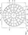
FIG. 3 is a top perspective illustration of the impeller of the liquid ring pump ofFIG. 1 ; -
FIG. 4 is a cross-sectional illustration of the impeller ofFIG. 3 ; and -
FIG. 5 is an enlarged cross-sectional illustration of the impeller ofFIG. 3 . - While the invention will be described in connection with certain preferred embodiments, there is no intent to limit it to those embodiments. On the contrary, the intent is to cover all alternatives and modifications as included within the scope of the invention as defined by the appended claims.
-
FIGS. 1 and2 are simplified cross-sectional illustrations of an embodiment of a side channel liquid ring pump 100 (also referred to as "pump 100") according to an embodiment of the present invention. Thepump 100 is designed to draw suction and pump both liquids and gases as well as mixed gas and liquids. Thepump 100 finds particular applicability in fuel systems and particularly fuel systems for aircraft such as helicopters. - The
pump 100 includes ahousing 102 that housesimpeller 104 within acavity 106 of thehousing 102. Thehousing 102 includes aninlet port 108 and adischarge port 110. Thecavity 106 defines aside channel 112 in portion of the radiallyouter periphery 114 ofcavity 106. The inlet and dischargeports impeller 104 so as to reduce the size of thepump 100 and to make it more suitable for use on aircraft and particularly helicopters. - The
impeller 104 is operably attached to aninput shaft 116 that rotates theimpeller 104 about a centralrotational axis 118. - The
impeller 104 includes acentral hub 120 from which a plurality of angularly spaced apartprimary vanes 122 extend radially outward.Distal end portions 124 of theprimary vanes 122 are angularly attached by areinforcement ring 126. A plurality ofsecondary vanes 130 are also attached to thereinforcement ring 126. Theimpeller 104 is configured such that the vanes alternate angularly between aprimary vane 122 and asecondary vane 130 such that each pair of adjacentprimary vanes 122 has a correspondingsecondary vane 130 positioned angularly therebetween. - The impeller has a
port side 132 and aback side 134 opposite theport side 132 such that theport side 132 and backside 134 are axially spaced apart along centralrotational axis 118. Theport side 132 is positioned adjacent to the inlet and dischargeports - The
central hub 120 tapers radially outward relative to centralrotational axis 118 when moving axially along the centralrotational axis 118 from theport side 132 to theback side 134 at an angle α. This conical angled geometry for thecentral hub 120 improves the air pumping capabilities and prevents air pockets from collecting on thecentral hub 120. The radius R1 of thecentral hub 120 proximate theport side 132 is smaller than the radius R2 of thecentral hub 120 proximate theback side 134. - As the
impeller 104 rotates about centralrotational axis 118 the heavier fuel (e.g. liquid) particles are accelerated on the radius and flung radially outward toward the outerradial periphery 114 of theimpeller cavity 106 causing an air within the fluid flow to collect near thecentral hub 120. A pressure gradient is established with the pressure in theside channel 112 greater than proximate the pressure at the hub. - The angle α of the outer surface of the
central hub 120 is set such that a pressure gradient is developed on theouter surface 140 of thecentral hub 120 from P1 to P2, which is defined by the rotational speed of the impeller and the hub radius at each location. Due to the angle α, P2 is greater than P1. When operating on a mixed flow, i.e. a flow with both fuel and air, the heavier fuel particles will migrate to P2, forcing the air bubbles toward theport side 132 and P1. This also draws the air bubbles closer to thedischarge port 110, where the air may then be swept into thedischarge port 110. - By being able to locate both the inlet and discharge
ports housing 102, the envelope of the system can be significantly reduced. - The use of the terms "a" and "an" and "the" and similar referents in the context of describing the invention (especially in the context of the following claims) is to be construed to cover both the singular and the plural, unless otherwise indicated herein or clearly contradicted by context. The terms "comprising," "having," "including," and "containing" are to be construed as open-ended terms (i.e., meaning "including, but not limited to,") unless otherwise noted. All methods described herein can be performed in any suitable order unless otherwise indicated herein or otherwise clearly contradicted by context. The use of any and all examples, or exemplary language (e.g., "such as") provided herein, is intended merely to better illuminate the invention and does not pose a limitation on the scope of the invention unless otherwise claimed. No language in the specification should be construed as indicating any non-claimed element as essential to the practice of the invention.
- Preferred embodiments of this invention are described herein, including the best mode known to the inventors for carrying out the invention. Variations of those preferred embodiments may become apparent to those of ordinary skill in the art upon reading the foregoing description. The inventors expect skilled artisans to employ such variations as appropriate, and the inventors intend for the invention to be practiced otherwise than as specifically described herein.
Claims (7)
- An impeller (104) for a liquid ring pump (100) comprising:a central hub (120) that defines a central rotational axis (188) about which the impeller (104) rotates and a conical outer surface (140);a plurality of angularly spaced apart main vanes (122) extending radially outward from the conical outer surface (140), wherein the main vanes (122) have a port side (132) and a back side (134) that are axially spaced apart along the central rotational axis (118), wherein the back side (134) is opposite the port side (132) and the central hub (120) tapers radially outward relative to central rotational axis (118) when moving axially along the central rotational axis (118) from the port side (132) to the back side (134); anda reinforcing ring (126) connecting distal end portions (124) of adjacent main vanes (122), wherein the reinforcing ring (126) is axially positioned between the port side (132) of the main vanes (122) and the back side (134) of the main vanes (122).
- The impeller (104) of claim 1, further comprising a plurality of secondary vanes (130) extending axially from the reinforcing ring (126), the secondary vanes (130) being spaced radially outward from the conical outer surface (140) of the central hub (120).
- The impeller (104) of claim 2, wherein the main vanes (122) and secondary vanes (130) alternate angularly about the central rotational axis (118) such that a secondary vane (130) is positioned angularly between adjacent main vanes (122).
- A liquid ring pump (100) comprising:a housing (102) defining an impeller cavity (106), the impeller cavity (106) has an inlet port (108) and a discharge port (110);an impeller (104) according to any one of claims 1 to 5 positioned within the impeller cavity (106) for rotation about a central rotational axis (118),
wherein the plurality of angularly spaced apart main vanes (122) extends radially outward from the conical outer surface (140) relative to the central rotational axis (118). - The liquid ring pump (100) of claim 4, wherein the impeller (104) housing (102) defines a side channel (112) in a radial periphery thereof.
- A method of pumping an air/fuel mixture comprising:receiving a fuel and air through an inlet port (108) of an impeller housing (102) of a liquid ring pump (100);discharging the fuel and air through a discharge port (110) of the impeller housing (102);creating a pressure differential along a conical outer surface (140) of a central hub (120) of an impeller (104) located within an impeller cavity (106) of the impeller housing (102) for rotation about a central rotational axis (118), the impeller cavity (106) being in fluid communication with the inlet port (108) and discharge port (110), the impeller (104) including a plurality of main vanes (122) extending radially outward from the conical outer surface (140) relative to the central rotational axis (118), wherein the main vanes (122) have a port side (132) and a back side (134) that are axially spaced apart along the central rotational axis (118) and the central hub (120) tapers radially outward relative to central rotational axis (118) when moving axially along the central rotational axis (118) from the port side (132) to the back side (134),wherein the impeller comprises a reinforcing ring connecting distal end portions of adjacent main vanes, wherein the reinforcing ring (126) is axially positioned between the port side (132) of the main vanes (122) and the back side (134) of the main vanes (122).
- The method of claim 6, wherein the pressure differential reduces in pressure when moving along the conical surface (140) from the second radius toward the first radius.
Applications Claiming Priority (2)
| Application Number | Priority Date | Filing Date | Title |
|---|---|---|---|
| US13/962,008 US9695835B2 (en) | 2013-08-08 | 2013-08-08 | Side channel liquid ring pump and impeller for side channel liquid ring pump |
| PCT/US2014/050146 WO2015069346A1 (en) | 2013-08-08 | 2014-08-07 | Side channel liquid ring pump and impeller for side channel liquid ring pump |
Publications (2)
| Publication Number | Publication Date |
|---|---|
| EP3030787A1 EP3030787A1 (en) | 2016-06-15 |
| EP3030787B1 true EP3030787B1 (en) | 2020-04-22 |
Family
ID=52448794
Family Applications (1)
| Application Number | Title | Priority Date | Filing Date |
|---|---|---|---|
| EP14838888.7A Active EP3030787B1 (en) | 2013-08-08 | 2014-08-07 | Side channel liquid ring pump and impeller for side channel liquid ring pump |
Country Status (5)
| Country | Link |
|---|---|
| US (1) | US9695835B2 (en) |
| EP (1) | EP3030787B1 (en) |
| CN (2) | CN110608168A (en) |
| CA (1) | CA2920260C (en) |
| WO (1) | WO2015069346A1 (en) |
Families Citing this family (2)
| Publication number | Priority date | Publication date | Assignee | Title |
|---|---|---|---|---|
| CN110748504B (en) * | 2019-11-15 | 2025-01-24 | 四川省自贡工业泵有限责任公司 | Hydraulic structure of side channel pump body |
| DE102022001696A1 (en) * | 2022-05-13 | 2023-11-16 | Truma Gerätetechnik GmbH & Co. KG | Two-stage pump |
Citations (2)
| Publication number | Priority date | Publication date | Assignee | Title |
|---|---|---|---|---|
| DE729453C (en) * | 1941-11-16 | 1942-12-16 | App U Maschinenfabrik Karl Dic | Impeller for circulation pumps with lateral guide channel |
| JPS5879686A (en) * | 1981-11-07 | 1983-05-13 | Fuji Electric Co Ltd | Impeller in elmo type pump |
Family Cites Families (11)
| Publication number | Priority date | Publication date | Assignee | Title |
|---|---|---|---|---|
| NL1752C (en) * | 1913-06-24 | 1917-01-02 | Siemens Schuckertwerke Gmbh | Vane pump with sealing rotating liquid ring |
| US1920484A (en) | 1929-05-27 | 1933-08-01 | Slemon Otto | Rotary pump |
| US3007417A (en) | 1958-07-16 | 1961-11-07 | Goulds Pumps | Liquid ring pump |
| US3002463A (en) | 1959-04-10 | 1961-10-03 | Lahti Petter | Rotary pump of the liquid ring type with side channels |
| US3583830A (en) * | 1969-01-21 | 1971-06-08 | Frank W Bailey | Liquid fuel burning apparatus |
| US4804313A (en) | 1987-03-24 | 1989-02-14 | Colt Industries Inc | Side channel self priming fuel pump having reservoir |
| DE8909839U1 (en) * | 1989-08-17 | 1991-01-31 | Siemens AG, 8000 München | Impeller for a liquid ring compressor |
| US5096386A (en) | 1989-11-17 | 1992-03-17 | Sundstrand Corporation | Integral liquid ring and regenerative pump |
| SE504976C2 (en) * | 1995-09-07 | 1997-06-02 | Kvaerner Pulping Tech | Fiber pulp suspension pump with built-in vacuum pump |
| US5961295A (en) * | 1997-07-03 | 1999-10-05 | The Nash Engineering Company | Mixed flow liquid ring pumps |
| WO2010133866A1 (en) | 2009-05-20 | 2010-11-25 | Edwards Limited | Side-channel pump with axial gas bearing |
-
2013
- 2013-08-08 US US13/962,008 patent/US9695835B2/en active Active
-
2014
- 2014-08-07 EP EP14838888.7A patent/EP3030787B1/en active Active
- 2014-08-07 WO PCT/US2014/050146 patent/WO2015069346A1/en not_active Ceased
- 2014-08-07 CN CN201911035236.8A patent/CN110608168A/en active Pending
- 2014-08-07 CN CN201480044657.6A patent/CN105531482A/en active Pending
- 2014-08-07 CA CA2920260A patent/CA2920260C/en active Active
Patent Citations (2)
| Publication number | Priority date | Publication date | Assignee | Title |
|---|---|---|---|---|
| DE729453C (en) * | 1941-11-16 | 1942-12-16 | App U Maschinenfabrik Karl Dic | Impeller for circulation pumps with lateral guide channel |
| JPS5879686A (en) * | 1981-11-07 | 1983-05-13 | Fuji Electric Co Ltd | Impeller in elmo type pump |
Also Published As
| Publication number | Publication date |
|---|---|
| WO2015069346A1 (en) | 2015-05-14 |
| CA2920260C (en) | 2019-04-09 |
| CN105531482A (en) | 2016-04-27 |
| CA2920260A1 (en) | 2015-05-14 |
| CN110608168A (en) | 2019-12-24 |
| US20150044015A1 (en) | 2015-02-12 |
| US9695835B2 (en) | 2017-07-04 |
| EP3030787A1 (en) | 2016-06-15 |
Similar Documents
| Publication | Publication Date | Title |
|---|---|---|
| CN103492733B (en) | Thrust bearing structure and possess the supercharger of this thrust bearing structure | |
| EP3149339B1 (en) | Extracting dry gas from a wet-gas compressor | |
| CN203384053U (en) | Rotary compressor | |
| EP2672120A2 (en) | Impeller, centrifugal pump including the same, and aircraft fuel system including the centrifugal pump | |
| JP6210459B2 (en) | Impeller and rotating machine | |
| US10746025B2 (en) | Turbine wheel, radial turbine, and supercharger | |
| EP3214315A1 (en) | Impeller, centrifugal fluid machine, and fluid device | |
| US11033845B2 (en) | Turbine engine and particle separators therefore | |
| US11261746B2 (en) | Turbine and turbocharger | |
| CA2920260C (en) | Side channel liquid ring pump and impeller for side channel liquid ring pump | |
| EP3473832B1 (en) | Turbine and turbocharger | |
| EP1892419A2 (en) | Two stage conical liquid ring pump having removable manifold, shims and first and second stage head o'ring receiving boss | |
| US11359642B2 (en) | Electric compressor | |
| EP3030786B1 (en) | Fuel system with liquid ring pump with centrifugal air/fuel separator | |
| JPH09512323A (en) | Feed pump | |
| EP3406914B1 (en) | Centrifugal rotating machine | |
| CN205638935U (en) | Vacuum pump compressor | |
| US2925043A (en) | Booster pump | |
| CN202746275U (en) | Centrifugal pump assembly with accelerating and multi-phase fluid separating transport | |
| JP5766461B2 (en) | Pump device | |
| CN103206403A (en) | Centrifugal pump component for accelerating separation and delivery of multi-phase fluid | |
| CN115450729A (en) | Centrifugal oil-gas separator and engine system | |
| CN121497634A (en) | An adaptive replenishment aviation fuel pump |
Legal Events
| Date | Code | Title | Description |
|---|---|---|---|
| PUAI | Public reference made under article 153(3) epc to a published international application that has entered the european phase |
Free format text: ORIGINAL CODE: 0009012 |
|
| 17P | Request for examination filed |
Effective date: 20160209 |
|
| AK | Designated contracting states |
Kind code of ref document: A1 Designated state(s): AL AT BE BG CH CY CZ DE DK EE ES FI FR GB GR HR HU IE IS IT LI LT LU LV MC MK MT NL NO PL PT RO RS SE SI SK SM TR |
|
| AX | Request for extension of the european patent |
Extension state: BA ME |
|
| DAX | Request for extension of the european patent (deleted) | ||
| RAP1 | Party data changed (applicant data changed or rights of an application transferred) |
Owner name: WOODWARD, INC. |
|
| STAA | Information on the status of an ep patent application or granted ep patent |
Free format text: STATUS: EXAMINATION IS IN PROGRESS |
|
| 17Q | First examination report despatched |
Effective date: 20190514 |
|
| GRAP | Despatch of communication of intention to grant a patent |
Free format text: ORIGINAL CODE: EPIDOSNIGR1 |
|
| STAA | Information on the status of an ep patent application or granted ep patent |
Free format text: STATUS: GRANT OF PATENT IS INTENDED |
|
| INTG | Intention to grant announced |
Effective date: 20200109 |
|
| GRAS | Grant fee paid |
Free format text: ORIGINAL CODE: EPIDOSNIGR3 |
|
| GRAA | (expected) grant |
Free format text: ORIGINAL CODE: 0009210 |
|
| STAA | Information on the status of an ep patent application or granted ep patent |
Free format text: STATUS: THE PATENT HAS BEEN GRANTED |
|
| AK | Designated contracting states |
Kind code of ref document: B1 Designated state(s): AL AT BE BG CH CY CZ DE DK EE ES FI FR GB GR HR HU IE IS IT LI LT LU LV MC MK MT NL NO PL PT RO RS SE SI SK SM TR |
|
| REG | Reference to a national code |
Ref country code: CH Ref legal event code: EP |
|
| REG | Reference to a national code |
Ref country code: IE Ref legal event code: FG4D |
|
| REG | Reference to a national code |
Ref country code: DE Ref legal event code: R096 Ref document number: 602014064255 Country of ref document: DE |
|
| REG | Reference to a national code |
Ref country code: AT Ref legal event code: REF Ref document number: 1260457 Country of ref document: AT Kind code of ref document: T Effective date: 20200515 |
|
| REG | Reference to a national code |
Ref country code: LT Ref legal event code: MG4D |
|
| REG | Reference to a national code |
Ref country code: NL Ref legal event code: MP Effective date: 20200422 |
|
| PG25 | Lapsed in a contracting state [announced via postgrant information from national office to epo] |
Ref country code: FI Free format text: LAPSE BECAUSE OF FAILURE TO SUBMIT A TRANSLATION OF THE DESCRIPTION OR TO PAY THE FEE WITHIN THE PRESCRIBED TIME-LIMIT Effective date: 20200422 Ref country code: NO Free format text: LAPSE BECAUSE OF FAILURE TO SUBMIT A TRANSLATION OF THE DESCRIPTION OR TO PAY THE FEE WITHIN THE PRESCRIBED TIME-LIMIT Effective date: 20200722 Ref country code: GR Free format text: LAPSE BECAUSE OF FAILURE TO SUBMIT A TRANSLATION OF THE DESCRIPTION OR TO PAY THE FEE WITHIN THE PRESCRIBED TIME-LIMIT Effective date: 20200723 Ref country code: IS Free format text: LAPSE BECAUSE OF FAILURE TO SUBMIT A TRANSLATION OF THE DESCRIPTION OR TO PAY THE FEE WITHIN THE PRESCRIBED TIME-LIMIT Effective date: 20200822 Ref country code: SE Free format text: LAPSE BECAUSE OF FAILURE TO SUBMIT A TRANSLATION OF THE DESCRIPTION OR TO PAY THE FEE WITHIN THE PRESCRIBED TIME-LIMIT Effective date: 20200422 Ref country code: LT Free format text: LAPSE BECAUSE OF FAILURE TO SUBMIT A TRANSLATION OF THE DESCRIPTION OR TO PAY THE FEE WITHIN THE PRESCRIBED TIME-LIMIT Effective date: 20200422 Ref country code: PT Free format text: LAPSE BECAUSE OF FAILURE TO SUBMIT A TRANSLATION OF THE DESCRIPTION OR TO PAY THE FEE WITHIN THE PRESCRIBED TIME-LIMIT Effective date: 20200824 Ref country code: NL Free format text: LAPSE BECAUSE OF FAILURE TO SUBMIT A TRANSLATION OF THE DESCRIPTION OR TO PAY THE FEE WITHIN THE PRESCRIBED TIME-LIMIT Effective date: 20200422 |
|
| REG | Reference to a national code |
Ref country code: AT Ref legal event code: MK05 Ref document number: 1260457 Country of ref document: AT Kind code of ref document: T Effective date: 20200422 |
|
| PG25 | Lapsed in a contracting state [announced via postgrant information from national office to epo] |
Ref country code: BG Free format text: LAPSE BECAUSE OF FAILURE TO SUBMIT A TRANSLATION OF THE DESCRIPTION OR TO PAY THE FEE WITHIN THE PRESCRIBED TIME-LIMIT Effective date: 20200722 Ref country code: HR Free format text: LAPSE BECAUSE OF FAILURE TO SUBMIT A TRANSLATION OF THE DESCRIPTION OR TO PAY THE FEE WITHIN THE PRESCRIBED TIME-LIMIT Effective date: 20200422 Ref country code: LV Free format text: LAPSE BECAUSE OF FAILURE TO SUBMIT A TRANSLATION OF THE DESCRIPTION OR TO PAY THE FEE WITHIN THE PRESCRIBED TIME-LIMIT Effective date: 20200422 Ref country code: RS Free format text: LAPSE BECAUSE OF FAILURE TO SUBMIT A TRANSLATION OF THE DESCRIPTION OR TO PAY THE FEE WITHIN THE PRESCRIBED TIME-LIMIT Effective date: 20200422 |
|
| PG25 | Lapsed in a contracting state [announced via postgrant information from national office to epo] |
Ref country code: AL Free format text: LAPSE BECAUSE OF FAILURE TO SUBMIT A TRANSLATION OF THE DESCRIPTION OR TO PAY THE FEE WITHIN THE PRESCRIBED TIME-LIMIT Effective date: 20200422 |
|
| REG | Reference to a national code |
Ref country code: DE Ref legal event code: R097 Ref document number: 602014064255 Country of ref document: DE |
|
| PG25 | Lapsed in a contracting state [announced via postgrant information from national office to epo] |
Ref country code: AT Free format text: LAPSE BECAUSE OF FAILURE TO SUBMIT A TRANSLATION OF THE DESCRIPTION OR TO PAY THE FEE WITHIN THE PRESCRIBED TIME-LIMIT Effective date: 20200422 Ref country code: EE Free format text: LAPSE BECAUSE OF FAILURE TO SUBMIT A TRANSLATION OF THE DESCRIPTION OR TO PAY THE FEE WITHIN THE PRESCRIBED TIME-LIMIT Effective date: 20200422 Ref country code: SM Free format text: LAPSE BECAUSE OF FAILURE TO SUBMIT A TRANSLATION OF THE DESCRIPTION OR TO PAY THE FEE WITHIN THE PRESCRIBED TIME-LIMIT Effective date: 20200422 Ref country code: DK Free format text: LAPSE BECAUSE OF FAILURE TO SUBMIT A TRANSLATION OF THE DESCRIPTION OR TO PAY THE FEE WITHIN THE PRESCRIBED TIME-LIMIT Effective date: 20200422 Ref country code: RO Free format text: LAPSE BECAUSE OF FAILURE TO SUBMIT A TRANSLATION OF THE DESCRIPTION OR TO PAY THE FEE WITHIN THE PRESCRIBED TIME-LIMIT Effective date: 20200422 Ref country code: IT Free format text: LAPSE BECAUSE OF FAILURE TO SUBMIT A TRANSLATION OF THE DESCRIPTION OR TO PAY THE FEE WITHIN THE PRESCRIBED TIME-LIMIT Effective date: 20200422 Ref country code: CZ Free format text: LAPSE BECAUSE OF FAILURE TO SUBMIT A TRANSLATION OF THE DESCRIPTION OR TO PAY THE FEE WITHIN THE PRESCRIBED TIME-LIMIT Effective date: 20200422 Ref country code: ES Free format text: LAPSE BECAUSE OF FAILURE TO SUBMIT A TRANSLATION OF THE DESCRIPTION OR TO PAY THE FEE WITHIN THE PRESCRIBED TIME-LIMIT Effective date: 20200422 |
|
| PG25 | Lapsed in a contracting state [announced via postgrant information from national office to epo] |
Ref country code: PL Free format text: LAPSE BECAUSE OF FAILURE TO SUBMIT A TRANSLATION OF THE DESCRIPTION OR TO PAY THE FEE WITHIN THE PRESCRIBED TIME-LIMIT Effective date: 20200422 Ref country code: SK Free format text: LAPSE BECAUSE OF FAILURE TO SUBMIT A TRANSLATION OF THE DESCRIPTION OR TO PAY THE FEE WITHIN THE PRESCRIBED TIME-LIMIT Effective date: 20200422 |
|
| PLBE | No opposition filed within time limit |
Free format text: ORIGINAL CODE: 0009261 |
|
| STAA | Information on the status of an ep patent application or granted ep patent |
Free format text: STATUS: NO OPPOSITION FILED WITHIN TIME LIMIT |
|
| 26N | No opposition filed |
Effective date: 20210125 |
|
| PG25 | Lapsed in a contracting state [announced via postgrant information from national office to epo] |
Ref country code: MC Free format text: LAPSE BECAUSE OF FAILURE TO SUBMIT A TRANSLATION OF THE DESCRIPTION OR TO PAY THE FEE WITHIN THE PRESCRIBED TIME-LIMIT Effective date: 20200422 |
|
| REG | Reference to a national code |
Ref country code: CH Ref legal event code: PL |
|
| PG25 | Lapsed in a contracting state [announced via postgrant information from national office to epo] |
Ref country code: LI Free format text: LAPSE BECAUSE OF NON-PAYMENT OF DUE FEES Effective date: 20200831 Ref country code: LU Free format text: LAPSE BECAUSE OF NON-PAYMENT OF DUE FEES Effective date: 20200807 Ref country code: CH Free format text: LAPSE BECAUSE OF NON-PAYMENT OF DUE FEES Effective date: 20200831 |
|
| REG | Reference to a national code |
Ref country code: BE Ref legal event code: MM Effective date: 20200831 |
|
| PG25 | Lapsed in a contracting state [announced via postgrant information from national office to epo] |
Ref country code: SI Free format text: LAPSE BECAUSE OF FAILURE TO SUBMIT A TRANSLATION OF THE DESCRIPTION OR TO PAY THE FEE WITHIN THE PRESCRIBED TIME-LIMIT Effective date: 20200422 |
|
| PG25 | Lapsed in a contracting state [announced via postgrant information from national office to epo] |
Ref country code: FR Free format text: LAPSE BECAUSE OF NON-PAYMENT OF DUE FEES Effective date: 20200831 |
|
| PG25 | Lapsed in a contracting state [announced via postgrant information from national office to epo] |
Ref country code: IE Free format text: LAPSE BECAUSE OF NON-PAYMENT OF DUE FEES Effective date: 20200807 Ref country code: BE Free format text: LAPSE BECAUSE OF NON-PAYMENT OF DUE FEES Effective date: 20200831 |
|
| PG25 | Lapsed in a contracting state [announced via postgrant information from national office to epo] |
Ref country code: TR Free format text: LAPSE BECAUSE OF FAILURE TO SUBMIT A TRANSLATION OF THE DESCRIPTION OR TO PAY THE FEE WITHIN THE PRESCRIBED TIME-LIMIT Effective date: 20200422 Ref country code: MT Free format text: LAPSE BECAUSE OF FAILURE TO SUBMIT A TRANSLATION OF THE DESCRIPTION OR TO PAY THE FEE WITHIN THE PRESCRIBED TIME-LIMIT Effective date: 20200422 Ref country code: CY Free format text: LAPSE BECAUSE OF FAILURE TO SUBMIT A TRANSLATION OF THE DESCRIPTION OR TO PAY THE FEE WITHIN THE PRESCRIBED TIME-LIMIT Effective date: 20200422 |
|
| PG25 | Lapsed in a contracting state [announced via postgrant information from national office to epo] |
Ref country code: MK Free format text: LAPSE BECAUSE OF FAILURE TO SUBMIT A TRANSLATION OF THE DESCRIPTION OR TO PAY THE FEE WITHIN THE PRESCRIBED TIME-LIMIT Effective date: 20200422 |
|
| PGFP | Annual fee paid to national office [announced via postgrant information from national office to epo] |
Ref country code: DE Payment date: 20250827 Year of fee payment: 12 |
|
| PGFP | Annual fee paid to national office [announced via postgrant information from national office to epo] |
Ref country code: GB Payment date: 20250827 Year of fee payment: 12 |