EP3030730B1 - A system and method for reducing the probability of detection of a communication and sensor mast - Google Patents
A system and method for reducing the probability of detection of a communication and sensor mast Download PDFInfo
- Publication number
- EP3030730B1 EP3030730B1 EP14834882.4A EP14834882A EP3030730B1 EP 3030730 B1 EP3030730 B1 EP 3030730B1 EP 14834882 A EP14834882 A EP 14834882A EP 3030730 B1 EP3030730 B1 EP 3030730B1
- Authority
- EP
- European Patent Office
- Prior art keywords
- mast
- upper portion
- actuator
- communication
- data
- Prior art date
- Legal status (The legal status is an assumption and is not a legal conclusion. Google has not performed a legal analysis and makes no representation as to the accuracy of the status listed.)
- Active
Links
Images

Classifications
-
- H—ELECTRICITY
- H01—ELECTRIC ELEMENTS
- H01Q—ANTENNAS, i.e. RADIO AERIALS
- H01Q3/00—Arrangements for changing or varying the orientation or the shape of the directional pattern of the waves radiated from an antenna or antenna system
- H01Q3/02—Arrangements for changing or varying the orientation or the shape of the directional pattern of the waves radiated from an antenna or antenna system using mechanical movement of antenna or antenna system as a whole
- H01Q3/04—Arrangements for changing or varying the orientation or the shape of the directional pattern of the waves radiated from an antenna or antenna system using mechanical movement of antenna or antenna system as a whole for varying one co-ordinate of the orientation
-
- H—ELECTRICITY
- H04—ELECTRIC COMMUNICATION TECHNIQUE
- H04B—TRANSMISSION
- H04B10/00—Transmission systems employing electromagnetic waves other than radio-waves, e.g. infrared, visible or ultraviolet light, or employing corpuscular radiation, e.g. quantum communication
- H04B10/11—Arrangements specific to free-space transmission, i.e. transmission through air or vacuum
- H04B10/112—Line-of-sight transmission over an extended range
-
- H—ELECTRICITY
- H01—ELECTRIC ELEMENTS
- H01Q—ANTENNAS, i.e. RADIO AERIALS
- H01Q1/00—Details of, or arrangements associated with, antennas
- H01Q1/12—Supports; Mounting means
- H01Q1/1242—Rigid masts specially adapted for supporting an aerial
-
- H—ELECTRICITY
- H04—ELECTRIC COMMUNICATION TECHNIQUE
- H04K—SECRET COMMUNICATION; JAMMING OF COMMUNICATION
- H04K3/00—Jamming of communication; Counter-measures
- H04K3/20—Countermeasures against jamming
- H04K3/22—Countermeasures against jamming including jamming detection and monitoring
- H04K3/224—Countermeasures against jamming including jamming detection and monitoring with countermeasures at transmission and/or reception of the jammed signal, e.g. stopping operation of transmitter or receiver, nulling or enhancing transmitted power in direction of or at frequency of jammer
-
- H—ELECTRICITY
- H04—ELECTRIC COMMUNICATION TECHNIQUE
- H04K—SECRET COMMUNICATION; JAMMING OF COMMUNICATION
- H04K3/00—Jamming of communication; Counter-measures
- H04K3/20—Countermeasures against jamming
- H04K3/25—Countermeasures against jamming based on characteristics of target signal or of transmission, e.g. using direct sequence spread spectrum or fast frequency hopping
-
- H—ELECTRICITY
- H04—ELECTRIC COMMUNICATION TECHNIQUE
- H04K—SECRET COMMUNICATION; JAMMING OF COMMUNICATION
- H04K3/00—Jamming of communication; Counter-measures
- H04K3/80—Jamming or countermeasure characterized by its function
- H04K3/82—Jamming or countermeasure characterized by its function related to preventing surveillance, interception or detection
- H04K3/827—Jamming or countermeasure characterized by its function related to preventing surveillance, interception or detection using characteristics of target signal or of transmission, e.g. using direct sequence spread spectrum or fast frequency hopping
-
- G—PHYSICS
- G01—MEASURING; TESTING
- G01S—RADIO DIRECTION-FINDING; RADIO NAVIGATION; DETERMINING DISTANCE OR VELOCITY BY USE OF RADIO WAVES; LOCATING OR PRESENCE-DETECTING BY USE OF THE REFLECTION OR RERADIATION OF RADIO WAVES; ANALOGOUS ARRANGEMENTS USING OTHER WAVES
- G01S13/00—Systems using the reflection or reradiation of radio waves, e.g. radar systems; Analogous systems using reflection or reradiation of waves whose nature or wavelength is irrelevant or unspecified
- G01S13/02—Systems using reflection of radio waves, e.g. primary radar systems; Analogous systems
- G01S2013/0236—Special technical features
- G01S2013/0281—LPI, Low Probability of Intercept radar
-
- H—ELECTRICITY
- H04—ELECTRIC COMMUNICATION TECHNIQUE
- H04K—SECRET COMMUNICATION; JAMMING OF COMMUNICATION
- H04K2203/00—Jamming of communication; Countermeasures
- H04K2203/30—Jamming or countermeasure characterized by the infrastructure components
- H04K2203/32—Jamming or countermeasure characterized by the infrastructure components including a particular configuration of antennas
-
- H—ELECTRICITY
- H04—ELECTRIC COMMUNICATION TECHNIQUE
- H04K—SECRET COMMUNICATION; JAMMING OF COMMUNICATION
- H04K2203/00—Jamming of communication; Countermeasures
- H04K2203/30—Jamming or countermeasure characterized by the infrastructure components
- H04K2203/36—Jamming or countermeasure characterized by the infrastructure components including means for exchanging jamming data between transmitter and receiver, e.g. in forward or backward direction
Definitions
- a system for reducing the probability of detection of a communication and sensor mast More precisely there is provided a system for reducing the probability of detection of a line of sight type communication and sensor mast, the mast having an upper portion extending upwardly relatively the ground, and a lower portion closer to the ground than the upper portion, where the mast at the upper portion is equipped with at least a communication or sensor element.
- the invention also includes a method for reducing the probability of detection of a line of sight type communication and sensor mast.
- Some communication and sensor systems depends on Line of Sight (LoS) or near LoS signal propagation. These includes systems that employ electromagnetic signals at relatively high frequencies.
- the term "communication and sensor mast” is here defined to be a mast that carries equipment for a system relying on LoS or near LoS signal propagation such as communication systems, radar systems, cameras and other sensor systems”.
- the purpose of the invention is to overcome or reduce at least one of the disadvantages of the prior art.
- the calculated instructions may be based on data from radio propagation analysis or data from a geospatial database. In these cases feedback is not utilized.
- a geospatial database is database that includes a 3D map or contour data.
- the calculated instructions may also include feedback data such as Received Signal Strength Indication data, bit error rate or other measure of the quality of the communication channel or the sensor input.
- the feedback could come from a video tracking system.
- the communication or sensor element at the upper portion of the mast may, apart from the elevation above ground setting, require an initial setting of the elevation angle relative the horizon and azimuth direction setting. These initial settings of the elevation above ground, elevation angle relative the horizon and azimuth direction may be calculated in a mission planning system. Settings and adjustments of the elevation angle and azimuth direction are not part of the invention.
- the moving object may typically be a vehicle or a person that may carry a radio or just be followed as in the case of the communication or sensor element being a radar antenna or a night or day camera.
- the communication may include any signals requiring Line of Sight or near Line of Sight.
- the method may comprise including use of data from a radio propagation analysis, from a geospatial database analysis or from a feedback analysis in the calculated instructions.
- a telescopic mast is employed due to its simplicity, low weight and load carrying capacity.
- the mast may be supported by a structure.
- the invention is however not limited to this type of mast, but applies to any type mast that is capable of changing elevation by use of an actuator.
- the actuator may be of any type such as hydraulic, pneumatic, screw spindle, wire rope or combination thereof.
- elevation sensing transducer is connected preferably to the actuator.
- the system includes an electronic drive.
- the drive is designed to calculate the required elevation of the mast upper portion based on one or more of the above-mentioned data. Further, the drive controls the actuator to move the upper portion to the required elevation where signals from the transducer indicates that the elevation is correct.
- the system and method according to the invention provides a useful contribution to a reduced probability of detection for a line of sight type communication and sensor mast.
- the reference number 1 denotes a telescopic mast that has an upper portion 2 and a lower portion 4. At its lower portion 4 that is close to the ground 6 the mast is equipped with an actuator 8 that is designed to move the upper portion 2 at least in the vertical direction, thus changing the elevation 10 of the upper portion 2 relative the ground 6.
- the mast 1 is carrying a communication or sensor element 12 at its upper portion 2.
- the communication or sensor element 12 is an antenna that is designed for Line of Sight 14 communication with an object 16.
- the communication or sensor element 12 has the elevation 10, an elevation angle 18 and an azimuth direction not shown, all of which have to be adjusted in order to achieve Line of Sight 14 communication.
- the actuator 8 here in the form of an electric linear worm screw actuator, has an elevation sensing transducer 20.
- the actuator 8 and the transducer 20 communicates through wires 22 with a drive system 24.
- the drive system 24 has the necessary hardware and software to calculate the desired elevation 10 of the mast 1 upper portion 2 based on inputs from a radio (transceiver) 26 or as outlined in the general part of this document. Then the drive system 24 controls the actuator 8 with its elevation sensing transducer 20 to the desired elevation 10.
- the drive system 24 extends the mast 1 until the signal quality is acceptable and then try to retract the upper portion 2 as much as possible retaining acceptable signal quality.
- the drive system 24 may repeat the calculations at desired intervals, and in the case of a moving object 16, sufficiently often to enable continuous contact with the object 16.
Landscapes
- Engineering & Computer Science (AREA)
- Computer Networks & Wireless Communication (AREA)
- Signal Processing (AREA)
- Radar, Positioning & Navigation (AREA)
- Remote Sensing (AREA)
- Physics & Mathematics (AREA)
- Electromagnetism (AREA)
- Radar Systems Or Details Thereof (AREA)
- Geophysics And Detection Of Objects (AREA)
- Small-Scale Networks (AREA)
- Testing Or Calibration Of Command Recording Devices (AREA)
- Variable-Direction Aerials And Aerial Arrays (AREA)
Description
- There is provided a system for reducing the probability of detection of a communication and sensor mast. More precisely there is provided a system for reducing the probability of detection of a line of sight type communication and sensor mast, the mast having an upper portion extending upwardly relatively the ground, and a lower portion closer to the ground than the upper portion, where the mast at the upper portion is equipped with at least a communication or sensor element. The invention also includes a method for reducing the probability of detection of a line of sight type communication and sensor mast.
- Some communication and sensor systems depends on Line of Sight (LoS) or near LoS signal propagation. These includes systems that employ electromagnetic signals at relatively high frequencies. The term "communication and sensor mast" is here defined to be a mast that carries equipment for a system relying on LoS or near LoS signal propagation such as communication systems, radar systems, cameras and other sensor systems".
- Systems relying on LoS signal propagation often have to be positioned on a mast that is elevated above the ground. The word ground also includes sea in this context.
- When such systems are utilized for defence purposes, the elevation may increase the probability of detection and thus for harmful physical and electronic attacks. Electronic attacks are often termed Electronic Warfare.
- Documents
US2005/093766 ,US2007/123122 andUS5977918 disclose altering the elevation of an antenna mast. - The purpose of the invention is to overcome or reduce at least one of the disadvantages of the prior art.
- The purpose is achieved according to the invention by the features as disclosed in the following patent claims.
- According to a first aspect of the invention there is provided a system for reducing the probability of detection of a line of sight type communication and sensor mast in accordance with
claim 1. - The calculated instructions may be based on data from radio propagation analysis or data from a geospatial database. In these cases feedback is not utilized.
- A geospatial database is database that includes a 3D map or contour data.
- The calculated instructions may also include feedback data such as Received Signal Strength Indication data, bit error rate or other measure of the quality of the communication channel or the sensor input.
- In the case a camera is used, the feedback could come from a video tracking system.
- The communication or sensor element at the upper portion of the mast may, apart from the elevation above ground setting, require an initial setting of the elevation angle relative the horizon and azimuth direction setting. These initial settings of the elevation above ground, elevation angle relative the horizon and azimuth direction may be calculated in a mission planning system. Settings and adjustments of the elevation angle and azimuth direction are not part of the invention.
- When an object is moving, the calculations and height adjustment are repeated sufficiently often to allow following of the moving object. The moving object may typically be a vehicle or a person that may carry a radio or just be followed as in the case of the communication or sensor element being a radar antenna or a night or day camera. The communication may include any signals requiring Line of Sight or near Line of Sight.
- According to a second aspect of the invention there is provided a method for reducing the probability of detection of a line of sight type communication and sensor mast in accordance with claim 9.
- The method may comprise including use of data from a radio propagation analysis, from a geospatial database analysis or from a feedback analysis in the calculated instructions.
- Often a telescopic mast is employed due to its simplicity, low weight and load carrying capacity. The mast may be supported by a structure. The invention is however not limited to this type of mast, but applies to any type mast that is capable of changing elevation by use of an actuator.
- The actuator may be of any type such as hydraulic, pneumatic, screw spindle, wire rope or combination thereof. And elevation sensing transducer is connected preferably to the actuator.
- In addition to the mast, actuator and transducer, the system includes an electronic drive. The drive is designed to calculate the required elevation of the mast upper portion based on one or more of the above-mentioned data. Further, the drive controls the actuator to move the upper portion to the required elevation where signals from the transducer indicates that the elevation is correct.
- The system and method according to the invention provides a useful contribution to a reduced probability of detection for a line of sight type communication and sensor mast.
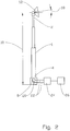
- Below, an example of a preferred device system and method is explained under reference to the enclosed drawings, where:
- Fig. 1
- shows a principal sketch of a system according to the invention in use; and
- Fig. 2
- shows a sketch of the system including some details.
- On the drawings the
reference number 1 denotes a telescopic mast that has anupper portion 2 and alower portion 4. At itslower portion 4 that is close to the ground 6 the mast is equipped with an actuator 8 that is designed to move theupper portion 2 at least in the vertical direction, thus changing theelevation 10 of theupper portion 2 relative the ground 6. - The
mast 1 is carrying a communication orsensor element 12 at itsupper portion 2. In this embodiment the communication orsensor element 12 is an antenna that is designed for Line of Sight 14 communication with anobject 16. - Referring now to
fig. 2 , the communication orsensor element 12 has theelevation 10, anelevation angle 18 and an azimuth direction not shown, all of which have to be adjusted in order to achieve Line ofSight 14 communication. - The actuator 8, here in the form of an electric linear worm screw actuator, has an elevation sensing transducer 20.
- The actuator 8 and the transducer 20 communicates through wires 22 with a
drive system 24. Thedrive system 24 has the necessary hardware and software to calculate the desiredelevation 10 of themast 1upper portion 2 based on inputs from a radio (transceiver) 26 or as outlined in the general part of this document. Then thedrive system 24 controls the actuator 8 with its elevation sensing transducer 20 to the desiredelevation 10. - The
drive system 24 extends themast 1 until the signal quality is acceptable and then try to retract theupper portion 2 as much as possible retaining acceptable signal quality. - The
drive system 24 may repeat the calculations at desired intervals, and in the case of amoving object 16, sufficiently often to enable continuous contact with theobject 16.
Claims (12)
- A system for reducing the probability of detection of a Line of Sight (14) type communication and sensor mast (1), the system comprising the mast (1), the mast (1) having an upper portion (2) extending upwardly relatively the ground (6), and a lower portion (4) closer to the ground (6) than the upper portion (2), where the mast at the upper portion (2) is equipped with at least a communication or sensor element (12), the mast (1) is equipped with an actuator (8), wherein the actuator (8), based on calculated instructions, is designed to alter the elevation above ground (10) of the mast upper portion (2) so as to achieve an acceptable signal quality with the upper portion (2) of the mast (1) at the lowest possible elevation, the system further comprising a drive system (24) coupled to the actuator (8) for controlling the actuator (8), wherein the drive system (24) is configured for first extending the mast (1) until the signal quality is acceptable and then retracting the upper portion (2) as much as possible retaining acceptable signal quality.
- The system according to claim 1, wherein the calculated instructions includes data from a radio propagation analysis.
- The system according to claim 1, wherein the calculated instructions includes data from a geospatial database.
- The system according to claim 1, wherein the calculated instructions includes feedback data.
- The system according to claim 4, wherein the feedback data includes Received Signal Strength Indication data.
- The system according to claim 1, wherein the initial elevation above ground (10) is calculated in a mission planning system.
- The system according to claim 1, wherein that calculations and height adjustment are repeated sufficiently often to follow a moving object (16).
- The system according to claim 1, wherein the communication includes any signals requiring Line of Sight (14) or near Line of Sight (14).
- A method for reducing the probability of detection of a Line of Sight (14) type communication and sensor mast (1), the mast (1) having an upper portion (2) extending upwardly relatively the ground (6), and a lower portion (4) closer to the ground (6) than the upper portion (2), where the mast (1) at the upper portion (2) is equipped with at least a communication or sensor element (12), and an actuator (8) and a drive system (24) coupled to the actuator (8) for controlling the actuator (8), the method includes altering, by the actuator (8), the elevation above ground (10) of the mast (1) upper portion (2), based on calculated instructions, so as to achieve an acceptable signal quality with the upper portion (2) of the mast (1) at the lowest possible elevation wherein the method comprises first extending, by the drive system (24), the mast (1) until the signal quality is acceptable and then retracting the upper portion (2) as much as possible retaining acceptable signal quality.
- The method according to claim 9, wherein the method comprises including use of data from a radio propagation analysis in the calculated instructions.
- The method according to claim 9, wherein the method comprises including data from a geospatial database analysis in the calculated instructions.
- The method according to claim 9, wherein the method comprises including data from a feedback analysis in the calculated instructions.
Priority Applications (2)
| Application Number | Priority Date | Filing Date | Title |
|---|---|---|---|
| SI201431871T SI3030730T1 (en) | 2013-08-09 | 2014-08-06 | A system and method for reducing the probability of detection of a communication and sensor mast |
| PL14834882T PL3030730T3 (en) | 2013-08-09 | 2014-08-06 | A system and method for reducing the probability of detection of a communication and sensor mast |
Applications Claiming Priority (3)
| Application Number | Priority Date | Filing Date | Title |
|---|---|---|---|
| US201361863995P | 2013-08-09 | 2013-08-09 | |
| US201461955512P | 2014-03-19 | 2014-03-19 | |
| PCT/NO2014/050139 WO2015020533A1 (en) | 2013-08-09 | 2014-08-06 | A system and method for reducing the probability of detection of a communication and sensor mast |
Publications (3)
| Publication Number | Publication Date |
|---|---|
| EP3030730A1 EP3030730A1 (en) | 2016-06-15 |
| EP3030730A4 EP3030730A4 (en) | 2017-04-12 |
| EP3030730B1 true EP3030730B1 (en) | 2021-05-19 |
Family
ID=52461728
Family Applications (1)
| Application Number | Title | Priority Date | Filing Date |
|---|---|---|---|
| EP14834882.4A Active EP3030730B1 (en) | 2013-08-09 | 2014-08-06 | A system and method for reducing the probability of detection of a communication and sensor mast |
Country Status (11)
| Country | Link |
|---|---|
| US (1) | US9876281B2 (en) |
| EP (1) | EP3030730B1 (en) |
| AU (1) | AU2014305229B2 (en) |
| BR (1) | BR112016002370B1 (en) |
| CA (1) | CA2919994C (en) |
| DK (1) | DK3030730T3 (en) |
| ES (1) | ES2882093T3 (en) |
| PL (1) | PL3030730T3 (en) |
| SI (1) | SI3030730T1 (en) |
| WO (1) | WO2015020533A1 (en) |
| ZA (1) | ZA201601504B (en) |
Family Cites Families (7)
| Publication number | Priority date | Publication date | Assignee | Title |
|---|---|---|---|---|
| US6046706A (en) | 1997-06-20 | 2000-04-04 | Vargas; Robert A. | Antenna mast and method of using same |
| US5977918A (en) * | 1997-09-25 | 1999-11-02 | The United States Of America As Represented By The Secretary Of The Navy | Extendible planar phased array mast |
| US6888512B1 (en) * | 2003-08-04 | 2005-05-03 | David John Daigler | Mobile telescopic antenna mount for wireless networking site surveys |
| US6906684B2 (en) * | 2003-10-30 | 2005-06-14 | Deere & Company | Controlling a telescopic antenna mast |
| US7226328B1 (en) * | 2005-02-16 | 2007-06-05 | Raytheon Company | Extendable spar buoy sea-based communication system |
| US8248473B2 (en) * | 2006-10-05 | 2012-08-21 | Graber Curtis E | Robotic sentry with low dispersion acoustic projector |
| US20110007157A1 (en) * | 2009-03-17 | 2011-01-13 | Stephen Sekelsky | Mechanical stabilization and automated positional corrections for stationary or mobile surveillance systems |
-
2014
- 2014-08-06 PL PL14834882T patent/PL3030730T3/en unknown
- 2014-08-06 ES ES14834882T patent/ES2882093T3/en active Active
- 2014-08-06 AU AU2014305229A patent/AU2014305229B2/en active Active
- 2014-08-06 DK DK14834882.4T patent/DK3030730T3/en active
- 2014-08-06 BR BR112016002370-6A patent/BR112016002370B1/en active IP Right Grant
- 2014-08-06 CA CA2919994A patent/CA2919994C/en active Active
- 2014-08-06 EP EP14834882.4A patent/EP3030730B1/en active Active
- 2014-08-06 SI SI201431871T patent/SI3030730T1/en unknown
- 2014-08-06 US US14/908,638 patent/US9876281B2/en active Active
- 2014-08-06 WO PCT/NO2014/050139 patent/WO2015020533A1/en not_active Ceased
-
2016
- 2016-03-04 ZA ZA2016/01504A patent/ZA201601504B/en unknown
Non-Patent Citations (1)
| Title |
|---|
| None * |
Also Published As
| Publication number | Publication date |
|---|---|
| AU2014305229B2 (en) | 2016-06-23 |
| PL3030730T3 (en) | 2021-11-08 |
| SI3030730T1 (en) | 2021-11-30 |
| AU2014305229A1 (en) | 2016-03-03 |
| WO2015020533A1 (en) | 2015-02-12 |
| ES2882093T3 (en) | 2021-12-01 |
| DK3030730T3 (en) | 2021-08-09 |
| US9876281B2 (en) | 2018-01-23 |
| CA2919994A1 (en) | 2015-02-12 |
| EP3030730A4 (en) | 2017-04-12 |
| US20160172751A1 (en) | 2016-06-16 |
| ZA201601504B (en) | 2017-09-27 |
| BR112016002370B1 (en) | 2022-02-15 |
| BR112016002370A2 (en) | 2017-08-01 |
| EP3030730A1 (en) | 2016-06-15 |
| CA2919994C (en) | 2021-05-18 |
Similar Documents
| Publication | Publication Date | Title |
|---|---|---|
| US11325702B2 (en) | Tethered aerial drone system | |
| US8446327B2 (en) | Compound two-way antenna with installation compensator | |
| US9188979B2 (en) | Method and system for remotely controlling a vehicle | |
| US9502764B2 (en) | Autonomous antenna tilt compensation | |
| WO2018013602A3 (en) | Wireless telecommunication antenna mount and control system | |
| EP2706673A1 (en) | Communication device, communication control method, and program | |
| KR102154326B1 (en) | Method and apparatus for beamforming in wireless communication system | |
| US10804972B2 (en) | Personal on-the-move satellite communications terminal | |
| JP2011151722A (en) | Radio apparatus, radio system, and antenna tracking method | |
| US10044112B2 (en) | Variable antenna and apparatus for detecting radio signal | |
| KR102244536B1 (en) | Apparatus for adjusting radiation pattern of a radar antenna and a radar apparatus for a vehicle | |
| US20160352009A1 (en) | Antenna device and antenna device control method | |
| EP3639050A1 (en) | Radio beacon system | |
| JP6984448B2 (en) | Sight, radio sensor and adjustment method | |
| AU2014305229B2 (en) | A system and method for reducing the probability of detection of a communication and sensor mast | |
| US10531417B2 (en) | Time synchronization system | |
| US8224241B1 (en) | System and method for antenna orientation for mobile applications | |
| JP5674318B2 (en) | Compound guidance device and compound guidance method | |
| EP2196817B1 (en) | An antenna measurement system and method thereof | |
| CN107576315A (en) | A kind of Geodetic Measuring System and its operating method | |
| CN113824516A (en) | Video receiving method, video receiving equipment and readable storage medium | |
| KR101443143B1 (en) | System for avoiding jamming and method thereof | |
| KR101550446B1 (en) | System and operation method for satellite antenna in capable of controlling the width of the beam | |
| KR20140115815A (en) | Radar System | |
| WO2016060569A1 (en) | System and method for protecting a deployable mast from abnormal operating conditions |
Legal Events
| Date | Code | Title | Description |
|---|---|---|---|
| PUAI | Public reference made under article 153(3) epc to a published international application that has entered the european phase |
Free format text: ORIGINAL CODE: 0009012 |
|
| 17P | Request for examination filed |
Effective date: 20160205 |
|
| AK | Designated contracting states |
Kind code of ref document: A1 Designated state(s): AL AT BE BG CH CY CZ DE DK EE ES FI FR GB GR HR HU IE IS IT LI LT LU LV MC MK MT NL NO PL PT RO RS SE SI SK SM TR |
|
| AX | Request for extension of the european patent |
Extension state: BA ME |
|
| DAX | Request for extension of the european patent (deleted) | ||
| A4 | Supplementary search report drawn up and despatched |
Effective date: 20170310 |
|
| RIC1 | Information provided on ipc code assigned before grant |
Ipc: H01Q 1/12 20060101ALI20170306BHEP Ipc: H01Q 3/04 20060101ALI20170306BHEP Ipc: E04H 12/18 20060101AFI20170306BHEP Ipc: H04B 10/112 20130101ALI20170306BHEP Ipc: G01S 13/02 20060101ALN20170306BHEP Ipc: H04K 3/00 20060101ALI20170306BHEP |
|
| STAA | Information on the status of an ep patent application or granted ep patent |
Free format text: STATUS: EXAMINATION IS IN PROGRESS |
|
| 17Q | First examination report despatched |
Effective date: 20191007 |
|
| GRAP | Despatch of communication of intention to grant a patent |
Free format text: ORIGINAL CODE: EPIDOSNIGR1 |
|
| STAA | Information on the status of an ep patent application or granted ep patent |
Free format text: STATUS: GRANT OF PATENT IS INTENDED |
|
| RIC1 | Information provided on ipc code assigned before grant |
Ipc: H04B 10/112 20130101ALI20201118BHEP Ipc: H01Q 1/12 20060101ALI20201118BHEP Ipc: E04H 12/18 20060101AFI20201118BHEP Ipc: H01Q 3/04 20060101ALI20201118BHEP Ipc: G01S 13/02 20060101ALN20201118BHEP Ipc: H04K 3/00 20060101ALI20201118BHEP |
|
| RIC1 | Information provided on ipc code assigned before grant |
Ipc: H04B 10/112 20130101ALI20201126BHEP Ipc: E04H 12/18 20060101AFI20201126BHEP Ipc: G01S 13/02 20060101ALN20201126BHEP Ipc: H01Q 3/04 20060101ALI20201126BHEP Ipc: H04K 3/00 20060101ALI20201126BHEP Ipc: H01Q 1/12 20060101ALI20201126BHEP |
|
| INTG | Intention to grant announced |
Effective date: 20201215 |
|
| GRAS | Grant fee paid |
Free format text: ORIGINAL CODE: EPIDOSNIGR3 |
|
| GRAA | (expected) grant |
Free format text: ORIGINAL CODE: 0009210 |
|
| STAA | Information on the status of an ep patent application or granted ep patent |
Free format text: STATUS: THE PATENT HAS BEEN GRANTED |
|
| AK | Designated contracting states |
Kind code of ref document: B1 Designated state(s): AL AT BE BG CH CY CZ DE DK EE ES FI FR GB GR HR HU IE IS IT LI LT LU LV MC MK MT NL NO PL PT RO RS SE SI SK SM TR |
|
| REG | Reference to a national code |
Ref country code: GB Ref legal event code: FG4D |
|
| REG | Reference to a national code |
Ref country code: CH Ref legal event code: EP |
|
| REG | Reference to a national code |
Ref country code: DE Ref legal event code: R096 Ref document number: 602014077585 Country of ref document: DE |
|
| REG | Reference to a national code |
Ref country code: AT Ref legal event code: REF Ref document number: 1394097 Country of ref document: AT Kind code of ref document: T Effective date: 20210615 |
|
| REG | Reference to a national code |
Ref country code: IE Ref legal event code: FG4D |
|
| REG | Reference to a national code |
Ref country code: DK Ref legal event code: T3 Effective date: 20210805 |
|
| REG | Reference to a national code |
Ref country code: FI Ref legal event code: FGE |
|
| REG | Reference to a national code |
Ref country code: SE Ref legal event code: TRGR |
|
| REG | Reference to a national code |
Ref country code: LT Ref legal event code: MG9D |
|
| REG | Reference to a national code |
Ref country code: AT Ref legal event code: MK05 Ref document number: 1394097 Country of ref document: AT Kind code of ref document: T Effective date: 20210519 |
|
| REG | Reference to a national code |
Ref country code: NO Ref legal event code: T2 Effective date: 20210519 |
|
| REG | Reference to a national code |
Ref country code: NL Ref legal event code: MP Effective date: 20210519 |
|
| PG25 | Lapsed in a contracting state [announced via postgrant information from national office to epo] |
Ref country code: HR Free format text: LAPSE BECAUSE OF FAILURE TO SUBMIT A TRANSLATION OF THE DESCRIPTION OR TO PAY THE FEE WITHIN THE PRESCRIBED TIME-LIMIT Effective date: 20210519 Ref country code: LT Free format text: LAPSE BECAUSE OF FAILURE TO SUBMIT A TRANSLATION OF THE DESCRIPTION OR TO PAY THE FEE WITHIN THE PRESCRIBED TIME-LIMIT Effective date: 20210519 Ref country code: BG Free format text: LAPSE BECAUSE OF FAILURE TO SUBMIT A TRANSLATION OF THE DESCRIPTION OR TO PAY THE FEE WITHIN THE PRESCRIBED TIME-LIMIT Effective date: 20210819 Ref country code: AT Free format text: LAPSE BECAUSE OF FAILURE TO SUBMIT A TRANSLATION OF THE DESCRIPTION OR TO PAY THE FEE WITHIN THE PRESCRIBED TIME-LIMIT Effective date: 20210519 |
|
| PG25 | Lapsed in a contracting state [announced via postgrant information from national office to epo] |
Ref country code: PT Free format text: LAPSE BECAUSE OF FAILURE TO SUBMIT A TRANSLATION OF THE DESCRIPTION OR TO PAY THE FEE WITHIN THE PRESCRIBED TIME-LIMIT Effective date: 20210920 Ref country code: RS Free format text: LAPSE BECAUSE OF FAILURE TO SUBMIT A TRANSLATION OF THE DESCRIPTION OR TO PAY THE FEE WITHIN THE PRESCRIBED TIME-LIMIT Effective date: 20210519 Ref country code: LV Free format text: LAPSE BECAUSE OF FAILURE TO SUBMIT A TRANSLATION OF THE DESCRIPTION OR TO PAY THE FEE WITHIN THE PRESCRIBED TIME-LIMIT Effective date: 20210519 Ref country code: GR Free format text: LAPSE BECAUSE OF FAILURE TO SUBMIT A TRANSLATION OF THE DESCRIPTION OR TO PAY THE FEE WITHIN THE PRESCRIBED TIME-LIMIT Effective date: 20210820 Ref country code: IS Free format text: LAPSE BECAUSE OF FAILURE TO SUBMIT A TRANSLATION OF THE DESCRIPTION OR TO PAY THE FEE WITHIN THE PRESCRIBED TIME-LIMIT Effective date: 20210919 |
|
| REG | Reference to a national code |
Ref country code: ES Ref legal event code: FG2A Ref document number: 2882093 Country of ref document: ES Kind code of ref document: T3 Effective date: 20211201 |
|
| PG25 | Lapsed in a contracting state [announced via postgrant information from national office to epo] |
Ref country code: NL Free format text: LAPSE BECAUSE OF FAILURE TO SUBMIT A TRANSLATION OF THE DESCRIPTION OR TO PAY THE FEE WITHIN THE PRESCRIBED TIME-LIMIT Effective date: 20210519 |
|
| PG25 | Lapsed in a contracting state [announced via postgrant information from national office to epo] |
Ref country code: RO Free format text: LAPSE BECAUSE OF FAILURE TO SUBMIT A TRANSLATION OF THE DESCRIPTION OR TO PAY THE FEE WITHIN THE PRESCRIBED TIME-LIMIT Effective date: 20210519 Ref country code: SM Free format text: LAPSE BECAUSE OF FAILURE TO SUBMIT A TRANSLATION OF THE DESCRIPTION OR TO PAY THE FEE WITHIN THE PRESCRIBED TIME-LIMIT Effective date: 20210519 Ref country code: SK Free format text: LAPSE BECAUSE OF FAILURE TO SUBMIT A TRANSLATION OF THE DESCRIPTION OR TO PAY THE FEE WITHIN THE PRESCRIBED TIME-LIMIT Effective date: 20210519 Ref country code: EE Free format text: LAPSE BECAUSE OF FAILURE TO SUBMIT A TRANSLATION OF THE DESCRIPTION OR TO PAY THE FEE WITHIN THE PRESCRIBED TIME-LIMIT Effective date: 20210519 Ref country code: CZ Free format text: LAPSE BECAUSE OF FAILURE TO SUBMIT A TRANSLATION OF THE DESCRIPTION OR TO PAY THE FEE WITHIN THE PRESCRIBED TIME-LIMIT Effective date: 20210519 |
|
| REG | Reference to a national code |
Ref country code: DE Ref legal event code: R097 Ref document number: 602014077585 Country of ref document: DE |
|
| PLBE | No opposition filed within time limit |
Free format text: ORIGINAL CODE: 0009261 |
|
| STAA | Information on the status of an ep patent application or granted ep patent |
Free format text: STATUS: NO OPPOSITION FILED WITHIN TIME LIMIT |
|
| PG25 | Lapsed in a contracting state [announced via postgrant information from national office to epo] |
Ref country code: MC Free format text: LAPSE BECAUSE OF FAILURE TO SUBMIT A TRANSLATION OF THE DESCRIPTION OR TO PAY THE FEE WITHIN THE PRESCRIBED TIME-LIMIT Effective date: 20210519 |
|
| 26N | No opposition filed |
Effective date: 20220222 |
|
| PG25 | Lapsed in a contracting state [announced via postgrant information from national office to epo] |
Ref country code: IS Free format text: LAPSE BECAUSE OF FAILURE TO SUBMIT A TRANSLATION OF THE DESCRIPTION OR TO PAY THE FEE WITHIN THE PRESCRIBED TIME-LIMIT Effective date: 20210919 Ref country code: LU Free format text: LAPSE BECAUSE OF NON-PAYMENT OF DUE FEES Effective date: 20210806 Ref country code: AL Free format text: LAPSE BECAUSE OF FAILURE TO SUBMIT A TRANSLATION OF THE DESCRIPTION OR TO PAY THE FEE WITHIN THE PRESCRIBED TIME-LIMIT Effective date: 20210519 |
|
| PG25 | Lapsed in a contracting state [announced via postgrant information from national office to epo] |
Ref country code: IE Free format text: LAPSE BECAUSE OF NON-PAYMENT OF DUE FEES Effective date: 20210806 |
|
| PG25 | Lapsed in a contracting state [announced via postgrant information from national office to epo] |
Ref country code: HU Free format text: LAPSE BECAUSE OF FAILURE TO SUBMIT A TRANSLATION OF THE DESCRIPTION OR TO PAY THE FEE WITHIN THE PRESCRIBED TIME-LIMIT; INVALID AB INITIO Effective date: 20140806 |
|
| P01 | Opt-out of the competence of the unified patent court (upc) registered |
Effective date: 20230524 |
|
| PG25 | Lapsed in a contracting state [announced via postgrant information from national office to epo] |
Ref country code: CY Free format text: LAPSE BECAUSE OF FAILURE TO SUBMIT A TRANSLATION OF THE DESCRIPTION OR TO PAY THE FEE WITHIN THE PRESCRIBED TIME-LIMIT Effective date: 20210519 |
|
| PG25 | Lapsed in a contracting state [announced via postgrant information from national office to epo] |
Ref country code: MK Free format text: LAPSE BECAUSE OF FAILURE TO SUBMIT A TRANSLATION OF THE DESCRIPTION OR TO PAY THE FEE WITHIN THE PRESCRIBED TIME-LIMIT Effective date: 20210519 |
|
| PG25 | Lapsed in a contracting state [announced via postgrant information from national office to epo] |
Ref country code: MT Free format text: LAPSE BECAUSE OF FAILURE TO SUBMIT A TRANSLATION OF THE DESCRIPTION OR TO PAY THE FEE WITHIN THE PRESCRIBED TIME-LIMIT Effective date: 20210519 |
|
| PGFP | Annual fee paid to national office [announced via postgrant information from national office to epo] |
Ref country code: SI Payment date: 20250715 Year of fee payment: 12 |
|
| PGFP | Annual fee paid to national office [announced via postgrant information from national office to epo] |
Ref country code: ES Payment date: 20250903 Year of fee payment: 12 Ref country code: FI Payment date: 20250811 Year of fee payment: 12 |
|
| PGFP | Annual fee paid to national office [announced via postgrant information from national office to epo] |
Ref country code: DK Payment date: 20250808 Year of fee payment: 12 Ref country code: DE Payment date: 20250806 Year of fee payment: 12 |
|
| PGFP | Annual fee paid to national office [announced via postgrant information from national office to epo] |
Ref country code: NO Payment date: 20250811 Year of fee payment: 12 |
|
| PGFP | Annual fee paid to national office [announced via postgrant information from national office to epo] |
Ref country code: IT Payment date: 20250818 Year of fee payment: 12 Ref country code: TR Payment date: 20250709 Year of fee payment: 12 Ref country code: PL Payment date: 20250710 Year of fee payment: 12 |
|
| PGFP | Annual fee paid to national office [announced via postgrant information from national office to epo] |
Ref country code: GB Payment date: 20250808 Year of fee payment: 12 Ref country code: BE Payment date: 20250811 Year of fee payment: 12 |
|
| PGFP | Annual fee paid to national office [announced via postgrant information from national office to epo] |
Ref country code: FR Payment date: 20250808 Year of fee payment: 12 |
|
| PGFP | Annual fee paid to national office [announced via postgrant information from national office to epo] |
Ref country code: CH Payment date: 20250901 Year of fee payment: 12 Ref country code: SE Payment date: 20250808 Year of fee payment: 12 |