EP3030382B1 - Apparatus for tightening threaded fasteners - Google Patents
Apparatus for tightening threaded fasteners Download PDFInfo
- Publication number
- EP3030382B1 EP3030382B1 EP14752746.9A EP14752746A EP3030382B1 EP 3030382 B1 EP3030382 B1 EP 3030382B1 EP 14752746 A EP14752746 A EP 14752746A EP 3030382 B1 EP3030382 B1 EP 3030382B1
- Authority
- EP
- European Patent Office
- Prior art keywords
- assembly
- drive shaft
- segment
- retaining
- self
- Prior art date
- Legal status (The legal status is an assumption and is not a legal conclusion. Google has not performed a legal analysis and makes no representation as to the accuracy of the status listed.)
- Active
Links
Images




Classifications
-
- B—PERFORMING OPERATIONS; TRANSPORTING
- B25—HAND TOOLS; PORTABLE POWER-DRIVEN TOOLS; MANIPULATORS
- B25B—TOOLS OR BENCH DEVICES NOT OTHERWISE PROVIDED FOR, FOR FASTENING, CONNECTING, DISENGAGING, OR HOLDING
- B25B21/00—Portable power-driven screw or nut setting or loosening tools; Attachments for drilling apparatus serving the same purpose
- B25B21/004—Portable power-driven screw or nut setting or loosening tools; Attachments for drilling apparatus serving the same purpose of the ratchet type
- B25B21/005—Portable power-driven screw or nut setting or loosening tools; Attachments for drilling apparatus serving the same purpose of the ratchet type driven by a radially acting hydraulic or pneumatic piston
-
- F—MECHANICAL ENGINEERING; LIGHTING; HEATING; WEAPONS; BLASTING
- F16—ENGINEERING ELEMENTS AND UNITS; GENERAL MEASURES FOR PRODUCING AND MAINTAINING EFFECTIVE FUNCTIONING OF MACHINES OR INSTALLATIONS; THERMAL INSULATION IN GENERAL
- F16D—COUPLINGS FOR TRANSMITTING ROTATION; CLUTCHES; BRAKES
- F16D1/00—Couplings for rigidly connecting two coaxial shafts or other movable machine elements
- F16D1/06—Couplings for rigidly connecting two coaxial shafts or other movable machine elements for attachment of a member on a shaft or on a shaft-end
- F16D1/08—Couplings for rigidly connecting two coaxial shafts or other movable machine elements for attachment of a member on a shaft or on a shaft-end with clamping hub; with hub and longitudinal key
- F16D1/0805—Couplings for rigidly connecting two coaxial shafts or other movable machine elements for attachment of a member on a shaft or on a shaft-end with clamping hub; with hub and longitudinal key with radial clamping due to deformation of a resilient body or a body of fluid
-
- B—PERFORMING OPERATIONS; TRANSPORTING
- B25—HAND TOOLS; PORTABLE POWER-DRIVEN TOOLS; MANIPULATORS
- B25B—TOOLS OR BENCH DEVICES NOT OTHERWISE PROVIDED FOR, FOR FASTENING, CONNECTING, DISENGAGING, OR HOLDING
- B25B21/00—Portable power-driven screw or nut setting or loosening tools; Attachments for drilling apparatus serving the same purpose
-
- B—PERFORMING OPERATIONS; TRANSPORTING
- B25—HAND TOOLS; PORTABLE POWER-DRIVEN TOOLS; MANIPULATORS
- B25B—TOOLS OR BENCH DEVICES NOT OTHERWISE PROVIDED FOR, FOR FASTENING, CONNECTING, DISENGAGING, OR HOLDING
- B25B23/00—Details of, or accessories for, spanners, wrenches, screwdrivers
-
- B—PERFORMING OPERATIONS; TRANSPORTING
- B25—HAND TOOLS; PORTABLE POWER-DRIVEN TOOLS; MANIPULATORS
- B25B—TOOLS OR BENCH DEVICES NOT OTHERWISE PROVIDED FOR, FOR FASTENING, CONNECTING, DISENGAGING, OR HOLDING
- B25B23/00—Details of, or accessories for, spanners, wrenches, screwdrivers
- B25B23/0007—Connections or joints between tool parts
- B25B23/0035—Connection means between socket or screwdriver bit and tool
-
- F—MECHANICAL ENGINEERING; LIGHTING; HEATING; WEAPONS; BLASTING
- F16—ENGINEERING ELEMENTS AND UNITS; GENERAL MEASURES FOR PRODUCING AND MAINTAINING EFFECTIVE FUNCTIONING OF MACHINES OR INSTALLATIONS; THERMAL INSULATION IN GENERAL
- F16C—SHAFTS; FLEXIBLE SHAFTS; ELEMENTS OR CRANKSHAFT MECHANISMS; ROTARY BODIES OTHER THAN GEARING ELEMENTS; BEARINGS
- F16C3/00—Shafts; Axles; Cranks; Eccentrics
- F16C3/02—Shafts; Axles
- F16C3/023—Shafts; Axles made of several parts, e.g. by welding
-
- F—MECHANICAL ENGINEERING; LIGHTING; HEATING; WEAPONS; BLASTING
- F16—ENGINEERING ELEMENTS AND UNITS; GENERAL MEASURES FOR PRODUCING AND MAINTAINING EFFECTIVE FUNCTIONING OF MACHINES OR INSTALLATIONS; THERMAL INSULATION IN GENERAL
- F16D—COUPLINGS FOR TRANSMITTING ROTATION; CLUTCHES; BRAKES
- F16D1/00—Couplings for rigidly connecting two coaxial shafts or other movable machine elements
- F16D1/10—Quick-acting couplings in which the parts are connected by simply bringing them together axially
Definitions
- Retainers for drive shafts in torque wrenches are well known and often include bushings or bearings using conventional spring clips, snap rings and/or separate cap assemblies. Often special tools are needed to install or remove these prior art solutions. Absent due care, components of prior art solutions are lost or damaged during tightening and/or loosening operations. Prior art solutions may include an attached chain or lanyard between the spring clip, snap ring and/or cap assembly and the drive shaft to reduce component loss and/or damage and increase safety. The chain or lanyard, however, is undesirably loose and dangles off of the tool. Operators often operate torque wrenches with improperly retained drive shafts. Components of prior art solutions not properly seated often come off creating dangerous and unsafe operating conditions.
- a self-retaining drive shaft assembly of unitary construction includes: a drive retainer drive shaft; a drive retainer cap; a drive retainer plunger; and a drive retainer segment assembly comprising a number of segments attached to the cap by a segment pin assembly.
- Advantageously retainer assembly is of unitary construction; requires no loose parts or external implements to engage and secure the drive shaft to the drive head of the tool; reduces likelihood of tool failure during operation due to improper engagement of the drive shaft; and increases user safety during tool operation.
- self-retaining drive shaft assembly 100 of unitary construction having an axis A includes: a drive retainer drive shaft 101; a drive retainer cap 102; a drive retainer plunger 103; and a drive retainer segment assembly 104.
- Segment assembly 104 is formed between drive shaft 101 and cap 102.
- Cap 102 is formed between segment assembly 104 and plunger 103.
- Segment assembly 104, cap 102 and plunger 103 are formed adjacent and substantially within drive shaft 101.
- a reaction force assembly 120 is also shown and includes: a spline sleeve bushing 121; a reaction arm bushing 122; and a set screw 123.
- FIGs. 1A-1F show assembly 100 fully engaged.
- FIG. 2 shows an exploded view of most component parts of assembly 100.
- Assembly 100 also includes segments 104A-D of retainer assembly 104; a wave spring 110; a ball bearing assembly 111 with ball bearing holes 111A-D and ball bearings 111E-H; a mounting screw 112; a retaining ring 113; a retaining o-ring 114; and a segment pin assembly 115 with segment holes 115A-D and segment pins 115E-H.
- Retaining o-ring 114 is formed between drive shaft 101 and segment assembly 104.
- Segment assembly 104 is formed between retaining o-ring 114 and cap 102.
- Cap 102 is formed between segment assembly and wave spring 110.
- Wave spring 110 is formed between cap 102 and plunger 103.
- Plunger 103 is formed between wave spring 110 and mounting screw 112. And mounting screw 112 holds in place and prevents the component parts of drive shaft assembly 100 from coming apart.
- Drive shaft 101 is cylindrical in shape having a drive end 140 and a free end 150.
- Drive end 140 includes: a drive adaptor 141; bearing surfaces 142 and 143; and a recess 144 formed between bearing surfaces 142 and 143.
- Drive adaptor 141 interfaces with a drive socket of a torque tool having a fastener, such as a nut or a bolt to be driven (not shown).
- drive adaptor 141 is a square drive, although it is to be understood that it could be any other type of drive such as a cap screw drive, a socket drive or an alien key drive, etc.
- Bearing surfaces 142 and 143 rotatably connect reaction force assembly 120 to drive shaft 101 by accepting spline sleeve bushing 121.
- Spline sleeve bushing 121 accepts reaction arm bushing 122 which are held in place by set screw 123 protruding into in recess 144.
- Reaction force assembly 120 freely rotates relative to drive shaft 101.
- Free end 150 includes a drive force assembly 130 including an external spline 131 and a bearing surface 151 with a chamfered edge 152 adjacent to a recess 153.
- Recess 153 includes a first bore 155 having a radius larger than a second bore 160 having a larger radius than a third bore 167.
- First bore 155 includes a wall 156 which runs parallel to axis A and is separated from an internal face 158 by a chamfered edge 157.
- Second bore 160 includes an upper wall 161 and a lower wall 162 which run parallel to axis A and wall 156 and are separated by a recess 163.
- Upper wall 161 is separated from internal face 158 of first bore 155 by a chamfered edge 164.
- Lower wall 162 is separated from an internal face 166 by a chamfered edge 165.
- Third bore 167 may extend into drive end 140 and includes internal threads 168 to receive an end of mounting screw 112.
- Segment assembly 104 includes four segments 104A-D, each of equal size and dimension with arc lengths of approximately 90°.
- Segment 104A is generally shaped as one quarter (1 ⁇ 4) of a cylindrical solid and includes: a first 1 ⁇ 4 cylindrical solid portion segment 171; a second 1 ⁇ 4 cylindrical solid portion segment 181; a 1 ⁇ 4 hollow solid disc portion segment 191 which connects first and second segments 171 and 181.
- First 1/4 cylindrical solid portion segment 171 includes: an inner wall 172; an outer wall 173; a first side wall 174; a second side wall 175; a bottom wall 176; a chamfered edge 177; and a drive retainer assembly segment pin bore 178 for segment pin 115A.
- Second 1 ⁇ 4 cylindrical solid portion segment 181 includes: a first inner wall 182; an outer wall 183; a first side wall 184; a second side wall 185; a bottom wall 186; a first chamfered edge 187; a second chamfered edge 188; a top wall 189; and a second inner wall 190.
- 1 ⁇ 4 hollow disc solid portion segment 191 includes: a top wall 192; and a bottom wall 193.
- Cap 102 is cylindrical in shape having a lower hollow cylindrical solid portion 201 and an upper hollow solid disc 209.
- Lower hollow cylindrical solid portion 201 includes: an outer wall 202; an inner wall 203; a bottom wall 204; a recess 205 having an upper bore 206 and a lower bore 208 of similar radius separated by a middle bore 207 of lesser radius; ball bearing assembly 111 with ball bearing holes 111A-D and ball bearings 111E-H; and segment pin assembly 115 with segment holes 115A-D and segment pins 115E-H.
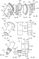
- FIG. 6 shows three views (6A-6C) of drive retainer plunger 103.
- Plunger 103 is cylindrical in shape having a connection end 210 and a depression end 225.
- Connection end 210 includes: an upper hollow recessed cylindrical solid 211; a lower hollow cylindrical solid 212; and a hollow solid disc 213.
- Upper solid 211 is separated from depression end 225 by a chamfered edge 214 above and a chamfered edge 215 below.
- Lower solid 212 extends below disc 213 and includes an outer o-ring edging 216 and a recess 218 having an inner wall 219.
- Depression end 225 includes a recess 226; an outer wall 227; an inner wall 228; an inner chamfered edge 229; and an upper wall 230.
- Recess 226 has a radius larger than recess 218.
- FIGs. 7A-7C component parts of assembly 100' are attached but assembly 100' is in a disengaged and unlocked position 2'.
- Segment pin assembly 115' attaches segments 104A'-D' to cap 102'.
- Wave spring 110' separates cap 102' from plunger 103'.
- Retaining o-ring 114' is placed adjacent bottom wall 193.
- Assembly 100' is ready to be installed in a tool 1, as shown in FIGs. 10A-10F .
- Mounting screw 112 holds in place and prevents component parts from coming out of assembly 100'.
- a user depresses plunger 103' with a pushing force 95'.
- plunger 103' and segment assembly 104' move downward into and around drive shaft 101.
- Wave spring 110' starts to compress.
- Ball bearings 111E'-H' begin to retract into ball bearing holes 111A'-D' of ball bearing assembly 111' as disc 213' moves downward.
- O-ring 114' begins to expand thereby increasing an inward compression force 96' against segments 104A'-D'. Nonetheless segments 104A'-D' ride along chamfered edge 152 and expand outward to fill recess 153.
- retainer assembly 100'" and component parts are in a fully engaged and locked position 2"'.
- the user fully depresses plunger 103'" with pushing force 95'".
- Cap 102"', plunger 103'" and segment assembly 104'" are within and around drive shaft 101.
- wave spring 110' decompresses which forces plunger 103'" upward.
- Ball bearings 111E"-H” retract into recess 163 of drive shaft 101 as disc 213" moves upward with plunger 103"'.
- O-ring 114" fully expands thereby increasing inward compression force 96'" against segments 104A"'-D"'.
- Segments 104A'"-D'" substantially surround bearing surface 151 and expand to substantially fill recess 153. Indeed outer wall 173 and of segments 104A"'-104D'" are adjacent wall 156 of first bore 153. Note that FIGs. 1A-1F are similar to FIGs. 9A-9C .
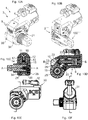
- FIGs. 10A-10F show torque tool 1 having retainer assembly 100"' and its component parts in a fully engaged and locked position 2"'.
- Torque tool 1 includes a housing 3 having two housing portions, a cylinder portion 4 and a driving portion 5.
- a cylinder-piston assembly 6 is arranged in cylinder housing portion 4 and includes: a cylinder 7; a piston 8 reciprocatingly movable in cylinder 7 along a piston axis B; and a piston rod 9 connected with piston 8.
- a lever-type ratchet assembly 10 is arranged in driving housing portion 5 and connected to and drivable by cylinder-piston assembly 6.
- Ratchet assembly 10 includes a pair of drive plates 11 and 12 mounted side-by-side and having upper portions 13 and 14 forming a rod pin slot 15 therebetween and having aligned rod pin bores 16 and 17 for receiving a rod pin 18 mounted therein.
- Drive plates 11 and 12 are supported for partial rotation within driving portion 5 around a ratchet wheel 19.
- Lower portions 20 and 21 of drive plates 11 and 12 are shaped similarly as part of driving portion 5.
- Upper portions 13 and 14 of driving plates 11 and 12 define a generally triangular, downward opening area containing a similarly shaped drive pawl assembly 22.
- Drive pawl assembly 22 includes a drive pawl 23 that is mounted therein with limited vertical travel within an indention dictated by a drive pawl spring 24.
- Drive pawl spring 24 bears against the upper portion of drive pawl 23 for maintaining ratcheting spring pressure against drive pawl 23 and forcing drive pawl 23 against ratchet wheel 19.
- Ratchet wheel 19 has peripheral driven teeth 25 which mesh with driving teeth 26 on the underside of drive pawl 23.
- Drive pawl 23 is driven forward by drive plates 11 and 12 which is driven by piston rod 9. Likewise ratchet wheel driven teeth 25 are driven in forward rotation.
- Tool 1 also includes: a rear swivel assembly 30; an end cap cover 31; a swivel block assembly 32; an automatic reaction pawl assembly 33; a reaction force transfer assembly 36 having a first and a second housing connection means 34 and 35; and various plates, set screws, seals, retaining rings; o-rings, pins, and plugs.
- Tool 1 may be driven by any suitable means, such as hydraulically, pneumatically, electrically or manually driven.
- any suitable torque wrench mechanism with any suitable configuration and/or component could be employed to practice the invention.
- the user sends drive end 140 of disengaged retainer assembly 100' through ratchet 19 to engage with the drive train of torque wrench 1.
- Assembly 100' may be inserted into a drive bore 27 of tool 1 from either side and driven either in one rotary direction 91 to tighten a bolt with a turning force 90 another rotary direction 93 to loosen a bolt with a turning force 92.
- drive force assembly 130 nonrotatably connects assembly 100 to ratchet assembly 10.
- Ratchet assembly 10 is internally splined to mate in driving engagement with external spline 131.
- Reaction force assembly 120 nonrotatably connects assembly 100 to reaction force transfer assembly 36 integrated with driving housing portion 5 via a splined connection.
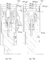
- FIG. 11A shows dimensions of retainer assembly 100' in disengaged position 2' while FIG. 11B shows dimensions of retainer assembly 100'" in fully engaged and locked position 2"'.
- Retainer assembly 100' has a height H 100' and widths W 104' , W 131 and W 122 , corresponding to the widths of segment assembly 104', external driving spline 131 and reaction arm bushing 122, respectively. Minimal gap exists between segments 104A'-104D'.
- Retainer assembly 100"' has a height H 100"'; ⁇ H 100"' corresponds to the decrease in height of retainer assembly 100'" in engaged and locked position 2'".
- Widths W 104"' , W 131 and W 122 correspond to the widths of segment assembly 104'", external driving spline 131 and reaction arm bushing 122, respectively.
- a gap exists between segments 104A"'-104D'", such that 2 * ⁇ W 104"' + W 104' W 104"' .
- W 104'" is greater than W 131 which locks retainer assembly 100"' into place and prevents it from falling out of tool 1.
- ⁇ W 104"' also corresponds to the distances segments 104A"'-104D"' expand within and to fill recess 153.
- segment assembly 104"' has a circular outer periphery which is greater than the diameter of external spline 131.
- retainer assembly 100 may be made in any suitable size(s) and from any suitable material(s).
- Advantageously retainer assembly 100 is of unitary construction; requires no loose parts or external implements to engage and secure the drive shaft to the drive head of the tool; reduces likelihood of tool failure during operation due to improper engagement of the drive shaft; and increases user safety during tool operation.
Landscapes
- Engineering & Computer Science (AREA)
- Mechanical Engineering (AREA)
- General Engineering & Computer Science (AREA)
- Ocean & Marine Engineering (AREA)
- Physics & Mathematics (AREA)
- Fluid Mechanics (AREA)
- Snaps, Bayonet Connections, Set Pins, And Snap Rings (AREA)
- Details Of Spanners, Wrenches, And Screw Drivers And Accessories (AREA)
- Connection Of Plates (AREA)
- Devices For Conveying Motion By Means Of Endless Flexible Members (AREA)
Description
- Retainers for drive shafts in torque wrenches are well known and often include bushings or bearings using conventional spring clips, snap rings and/or separate cap assemblies. Often special tools are needed to install or remove these prior art solutions. Absent due care, components of prior art solutions are lost or damaged during tightening and/or loosening operations. Prior art solutions may include an attached chain or lanyard between the spring clip, snap ring and/or cap assembly and the drive shaft to reduce component loss and/or damage and increase safety. The chain or lanyard, however, is undesirably loose and dangles off of the tool. Operators often operate torque wrenches with improperly retained drive shafts. Components of prior art solutions not properly seated often come off creating dangerous and unsafe operating conditions. Such prior art solutions are disclosed in
US 4 762 033 ,US 2003/0136230 A1 andDE 39 17 827 A1 that show a drive shaft that can be attached and detached to a torque output device such as a handle (US 4 762 033 andUS 2003/0136230 A1 ) or a fastener (DE 39 17 827 A1 ) by pressing down a plunger. In all cases radially movable balls are unlocked when the plunger is pressed down into the drive shaft, thereby loosening the connection of the drive shaft with the torque output device. - A self-retaining drive shaft assembly of unitary construction is invented and disclosed and includes: a drive retainer drive shaft; a drive retainer cap; a drive retainer plunger; and a drive retainer segment assembly comprising a number of segments attached to the cap by a segment pin assembly. Advantageously retainer assembly is of unitary construction; requires no loose parts or external implements to engage and secure the drive shaft to the drive head of the tool; reduces likelihood of tool failure during operation due to improper engagement of the drive shaft; and increases user safety during tool operation.
- The invention may be described, by way of example only, with reference to the accompanying drawings, of which:
-
FIG. 1A is a first isometric perspective view of a fully engaged and locked self-retaining drive shaft assembly of the present invention; -
FIG. 1B is a second isometric perspective view of the assembly ofFIG. 1 ; -
FIG. 1C is a side view of the assembly ofFIG. 1 ; -
FIG. 1D is a cross-section view showing internal parts of the assembly ofFIG. 1 ; -
FIG. 1E is a top view of the assembly ofFIG. 1 ; -
FIG. 1F is a bottom view of the assembly ofFIG. 1 ; -
FIG. 2 is an exploded side view of the assembly ofFIG. 1 ; -
FIGs. 3A-3D show various views of a drive shaft of the assembly ofFIG. 1 ; -
FIGs. 4A-4D show various views of a segment of a segment assembly of the assembly ofFIG. 1 ; -
FIGs. 5A-5C show various views of a cap of the assembly ofFIG. 1 ; -
FIGs. 6A-6C show various views of a plunger of the assembly ofFIG. 1 ; -
FIGs. 7A-7C show various views of a disengaged and unlocked self-retaining drive shaft assembly of the present invention; -
FIGs. 8A-8B show various views of a partially engaged and unlocked drive shaft assembly of the present invention; -
FIGs. 9A-9C show various views of the assembly ofFIG. 1 ; -
FIGs. 10A-10F show various views of a device for tightening or loosening threaded fasteners having the assembly ofFIG. 1 ; -
FIG. 11A is a cross-section view showing various dimensions of the assembly ofFIGs. 7A-7C ; and -
FIG. 11B is a cross-section view showing various dimensions of the assembly ofFIG. 1 . - Referring to
FIGs. 1A-1F , self-retainingdrive shaft assembly 100 of unitary construction having an axis A is shown and includes: a driveretainer drive shaft 101; adrive retainer cap 102; adrive retainer plunger 103; and a driveretainer segment assembly 104.Segment assembly 104 is formed betweendrive shaft 101 andcap 102.Cap 102 is formed betweensegment assembly 104 andplunger 103.Segment assembly 104,cap 102 andplunger 103 are formed adjacent and substantially withindrive shaft 101. Areaction force assembly 120 is also shown and includes: a spline sleeve bushing 121; a reaction arm bushing 122; and aset screw 123.FIGs. 1A- 1F show assembly 100 fully engaged. -
FIG. 2 shows an exploded view of most component parts ofassembly 100.Assembly 100 also includessegments 104A-D ofretainer assembly 104; awave spring 110; a ball bearing assembly 111 withball bearing holes 111A-D andball bearings 111E-H; amounting screw 112; aretaining ring 113; a retaining o-ring 114; and asegment pin assembly 115 with segment holes 115A-D and segment pins 115E-H. Retaining o-ring 114 is formed betweendrive shaft 101 andsegment assembly 104.Segment assembly 104 is formed between retaining o-ring 114 andcap 102.Cap 102 is formed between segment assembly andwave spring 110.Wave spring 110 is formed betweencap 102 andplunger 103. Plunger 103 is formed betweenwave spring 110 and mountingscrew 112. And mountingscrew 112 holds in place and prevents the component parts ofdrive shaft assembly 100 from coming apart. - Referring to
FIG. 3 , four views (3A-3D) are shown ofdrive shaft 101.Drive shaft 101 is cylindrical in shape having adrive end 140 and afree end 150. Driveend 140 includes: adrive adaptor 141; bearingsurfaces recess 144 formed between bearingsurfaces Drive adaptor 141 interfaces with a drive socket of a torque tool having a fastener, such as a nut or a bolt to be driven (not shown). As shown,drive adaptor 141 is a square drive, although it is to be understood that it could be any other type of drive such as a cap screw drive, a socket drive or an alien key drive, etc. Bearing surfaces 142 and 143 rotatably connectreaction force assembly 120 to driveshaft 101 by acceptingspline sleeve bushing 121.Spline sleeve bushing 121 acceptsreaction arm bushing 122 which are held in place byset screw 123 protruding into inrecess 144.Reaction force assembly 120 freely rotates relative to driveshaft 101. -
Free end 150 includes adrive force assembly 130 including anexternal spline 131 and abearing surface 151 with achamfered edge 152 adjacent to arecess 153.Recess 153 includes afirst bore 155 having a radius larger than asecond bore 160 having a larger radius than athird bore 167. First bore 155 includes awall 156 which runs parallel to axis A and is separated from aninternal face 158 by achamfered edge 157.Second bore 160 includes anupper wall 161 and alower wall 162 which run parallel to axis A andwall 156 and are separated by arecess 163.Upper wall 161 is separated frominternal face 158 offirst bore 155 by achamfered edge 164.Lower wall 162 is separated from aninternal face 166 by achamfered edge 165.Third bore 167 may extend intodrive end 140 and includesinternal threads 168 to receive an end of mountingscrew 112. - Referring to
FIG. 4 , four views (4A-4D) are shown of onesegment 104A ofsegment assembly 104.Segment assembly 104 includes foursegments 104A-D, each of equal size and dimension with arc lengths of approximately 90°.Segment 104A is generally shaped as one quarter (¼) of a cylindrical solid and includes: a first ¼ cylindricalsolid portion segment 171; a second ¼ cylindricalsolid portion segment 181; a ¼ hollow soliddisc portion segment 191 which connects first andsecond segments solid portion segment 171 includes: aninner wall 172; anouter wall 173; afirst side wall 174; asecond side wall 175; a bottom wall 176; achamfered edge 177; and a drive retainer assembly segment pin bore 178 for segment pin 115A. Second ¼ cylindricalsolid portion segment 181 includes: a firstinner wall 182; anouter wall 183; afirst side wall 184; asecond side wall 185; abottom wall 186; a firstchamfered edge 187; a secondchamfered edge 188; atop wall 189; and a secondinner wall 190. ¼ hollow discsolid portion segment 191 includes: atop wall 192; and abottom wall 193. - Referring to
FIG.5 , three views (5A-5C) are shown ofdrive retainer cap 102.Cap 102 is cylindrical in shape having a lower hollow cylindricalsolid portion 201 and an upper hollowsolid disc 209. Lower hollow cylindricalsolid portion 201 includes: anouter wall 202; aninner wall 203; abottom wall 204; arecess 205 having anupper bore 206 and alower bore 208 of similar radius separated by amiddle bore 207 of lesser radius; ball bearing assembly 111 with ball bearing holes 111A-D andball bearings 111E-H; andsegment pin assembly 115 with segment holes 115A-D and segment pins 115E-H. -
FIG. 6 shows three views (6A-6C) ofdrive retainer plunger 103.Plunger 103 is cylindrical in shape having aconnection end 210 and adepression end 225.Connection end 210 includes: an upper hollow recessed cylindrical solid 211; a lower hollow cylindrical solid 212; and a hollowsolid disc 213. Upper solid 211 is separated fromdepression end 225 by achamfered edge 214 above and achamfered edge 215 below. Lower solid 212 extends belowdisc 213 and includes an outer o-ring edging 216 and arecess 218 having aninner wall 219.Depression end 225 includes arecess 226; anouter wall 227; aninner wall 228; an innerchamfered edge 229; and anupper wall 230.Recess 226 has a radius larger thanrecess 218. - As shown in
FIGs. 7A-7C , component parts of assembly 100' are attached but assembly 100' is in a disengaged and unlocked position 2'. Segment pin assembly 115' attachessegments 104A'-D' to cap 102'. Wave spring 110' separates cap 102' from plunger 103'. Retaining o-ring 114' is placed adjacentbottom wall 193. Assembly 100' is ready to be installed in a tool 1, as shown inFIGs. 10A-10F . Mountingscrew 112 holds in place and prevents component parts from coming out of assembly 100'. - During engagement, a user depresses plunger 103' with a pushing force 95'. Generally cap 102', plunger 103' and segment assembly 104' move downward into and around drive
shaft 101. Wave spring 110' starts to compress.Ball bearings 111E'-H' begin to retract into ball bearing holes 111A'-D' of ball bearing assembly 111' as disc 213' moves downward. O-ring 114' begins to expand thereby increasing an inward compression force 96' againstsegments 104A'-D'. Nonethelesssegments 104A'-D' ride alongchamfered edge 152 and expand outward to fillrecess 153. - As shown in
FIGs. 8A and 8B , component parts ofassembly 100" are attached but assembly 100' is in a partially engaged andunlocked position 2". The user further depressesplunger 103" with pushingforce 95".Cap 102",plunger 103" andsegment assembly 104" move downward into and around driveshaft 101.Wave spring 110" further compresses.Ball bearings 111E"-H" further retract intoball bearing holes 111A"-D" of ball bearing assembly 111" asdisc 213" moves further downward. O-ring 114" further expands thereby increasinginward compression force 96" againstsegments 104A"-D". Nonethelesssegments 104A"-D" ride further alongchamfered edge 152 and expand further outward toward an engaged and locked position. - As shown in
FIGs. 9A-9C , retainer assembly 100'" and component parts are in a fully engaged and lockedposition 2"'. The user fully depresses plunger 103'" with pushing force 95'".Cap 102"', plunger 103'" and segment assembly 104'" are within and around driveshaft 101. Once the user removes pushingforce 95"', wave spring 110'" decompresses which forces plunger 103'" upward.Ball bearings 111E"-H" retract intorecess 163 ofdrive shaft 101 asdisc 213" moves upward withplunger 103"'. O-ring 114" fully expands thereby increasing inward compression force 96'" againstsegments 104A"'-D"'.Segments 104A'"-D'" substantially surround bearingsurface 151 and expand to substantially fillrecess 153. Indeedouter wall 173 and ofsegments 104A"'-104D'" areadjacent wall 156 offirst bore 153. Note thatFIGs. 1A-1F are similar toFIGs. 9A-9C . -
FIGs. 10A-10F show torque tool 1 havingretainer assembly 100"' and its component parts in a fully engaged and lockedposition 2"'. Torque tool 1 includes ahousing 3 having two housing portions, a cylinder portion 4 and a driving portion 5. A cylinder-piston assembly 6 is arranged in cylinder housing portion 4 and includes: a cylinder 7; a piston 8 reciprocatingly movable in cylinder 7 along a piston axis B; and a piston rod 9 connected with piston 8. - A lever-
type ratchet assembly 10 is arranged in driving housing portion 5 and connected to and drivable by cylinder-piston assembly 6.Ratchet assembly 10 includes a pair ofdrive plates upper portions rod pin slot 15 therebetween and having aligned rod pin bores 16 and 17 for receiving arod pin 18 mounted therein. Driveplates ratchet wheel 19.Lower portions drive plates Upper portions plates drive pawl assembly 22. - Drive
pawl assembly 22 includes adrive pawl 23 that is mounted therein with limited vertical travel within an indention dictated by adrive pawl spring 24. Drivepawl spring 24 bears against the upper portion ofdrive pawl 23 for maintaining ratcheting spring pressure againstdrive pawl 23 and forcingdrive pawl 23 againstratchet wheel 19.Ratchet wheel 19 has peripheral driventeeth 25 which mesh with drivingteeth 26 on the underside ofdrive pawl 23. Drivepawl 23 is driven forward bydrive plates teeth 25 are driven in forward rotation. When piston rod 9 is retracted,drive pawl spring 24 is extended bydrive pawl 23 when drivingteeth 26 ratchet back over ratchet wheel driventeeth 25 to the withdrawn position. These actions affectsretainer assembly 100"', generlly, and driveshaft 101, specifically, to rotate relative tohousing 3 around a drive axis A. - Tool 1 also includes: a
rear swivel assembly 30; anend cap cover 31; aswivel block assembly 32; an automaticreaction pawl assembly 33; a reaction force transfer assembly 36 having a first and a second housing connection means 34 and 35; and various plates, set screws, seals, retaining rings; o-rings, pins, and plugs. - Tool 1 may be driven by any suitable means, such as hydraulically, pneumatically, electrically or manually driven. Alternatively any suitable torque wrench mechanism with any suitable configuration and/or component could be employed to practice the invention.
- The user sends
drive end 140 of disengaged retainer assembly 100' throughratchet 19 to engage with the drive train of torque wrench 1. Assembly 100' may be inserted into a drive bore 27 of tool 1 from either side and driven either in one rotary direction 91 to tighten a bolt with a turning force 90 another rotary direction 93 to loosen a bolt with a turning force 92. Note that in either orientation, driveforce assembly 130 nonrotatably connects assembly 100 to ratchetassembly 10.Ratchet assembly 10 is internally splined to mate in driving engagement withexternal spline 131.Reaction force assembly 120 nonrotatably connects assembly 100 to reaction force transfer assembly 36 integrated with driving housing portion 5 via a splined connection. -
FIG. 11A shows dimensions of retainer assembly 100' in disengaged position 2' whileFIG. 11B shows dimensions of retainer assembly 100'" in fully engaged and lockedposition 2"'. Retainer assembly 100' has a height H100' and widths W104', W131 and W122, corresponding to the widths of segment assembly 104',external driving spline 131 andreaction arm bushing 122, respectively. Minimal gap exists betweensegments 104A'-104D'. -
Retainer assembly 100"' has a height H100"'; ΔH100"' corresponds to the decrease in height of retainer assembly 100'" in engaged and locked position 2'". Widths W104"', W131 and W122, correspond to the widths of segment assembly 104'",external driving spline 131 andreaction arm bushing 122, respectively. A gap exists betweensegments 104A"'-104D'", such that 2 * ΔW104"' + W104' = W104"'. Indeed W104'" is greater than W131 which locksretainer assembly 100"' into place and prevents it from falling out of tool 1. ΔW104"' also corresponds to thedistances segments 104A"'-104D"' expand within and to fillrecess 153. In other words,segment assembly 104"' has a circular outer periphery which is greater than the diameter ofexternal spline 131. - Note that
retainer assembly 100 may be made in any suitable size(s) and from any suitable material(s). -
Advantageously retainer assembly 100 is of unitary construction; requires no loose parts or external implements to engage and secure the drive shaft to the drive head of the tool; reduces likelihood of tool failure during operation due to improper engagement of the drive shaft; and increases user safety during tool operation. - applications without omitting features that, from the standpoint of prior art, fairly constitute essential characteristics of the generic or specific aspects of this invention.
- When used in this specification and claims, the terms "comprising", "including", "having" and variations thereof mean that the specified features, steps or integers are included. The terms are not to be interpreted to exclude the presence of other features, steps or components.
Claims (13)
- A self-retaining drive shaft assembly of unitary construction for use with a device for tightening and loosening of a threaded fastener, the drive shaft assembly including:a drive shaft (101);a cap (102);a plunger (103); anda segment assembly (104) comprising a number of segments (104A - 104D) attached to the cap (102) by a segment pin assembly (115).
- A self-retaining drive shaft assembly of unitary construction according to claim 1 wherein the segment assembly (104) is substantially formed between the drive shaft (101) and the cap (102), and wherein the cap (102) is formed between the segment assembly (104) and the plunger (103).
- A self-retaining drive shaft assembly of unitary construction according to any previous claim wherein the segment assembly (104), cap (102) and plunger (103) are substantially formed within the drive shaft (101).
- A self-retaining drive shaft assembly of unitary construction according to any previous claim wherein during operation a user presses the plunger (103) such that the cap (102), the plunger (103) and the segment assembly (104) move downward and into and around a recess in an upper portion of the drive shaft (101).
- A self-retaining drive shaft assembly of unitary construction according to any previous claim wherein the segment assembly (104) expands outward to substantially fill the recess.
- A self-retaining drive shaft assembly of unitary construction according to any previous claim wherein the height of a fully engaged and locked drive shaft assembly (100) is less than the height of a disengaged and unlocked drive shaft assembly (100).
- A self-retaining drive shaft assembly of unitary construction according to any previous claim wherein the width of the segment assembly (104) of a fully engaged and locked drive shaft assembly (100) is greater than the width of the segment assembly (104) of a disengaged and unlocked drive shaft assembly (100).
- A self-retaining drive shaft assembly of unitary construction according to any previous claim including:the drive shaft (101) having a drive force assembly (130) and a reaction force assembly (120);wherein the width of the segment assembly (104) is less than the width of the reaction force assembly of a disengaged and unlocked drive shaft assembly; andwherein the width of the segment assembly (104) is greater than the width of the reaction force assembly (120) of a fully engaged and locked drive shaft assembly which prevents it from falling out of the device.
- A self-retaining drive shaft assembly of unitary construction according to any previous claim including:a wave spring (110);a ball bearing assembly (111) having ball bearing holes and ball bearings (111A - 111D);a mounting screw (112);a retaining o-ring (114); anda segment pin assembly (115) with segment pin holes (115A - 115D) and segment pins (115E - 115H).
- A self-retaining drive shaft assembly of unitary construction according to any previous claim including:the retaining o-ring (114) formed between the drive shaft (101) and the segment assembly (104);the segment assembly (104) formed between the retaining o-ring (114) and the cap (102);the cap (102) formed between segment assembly (104) and the wave spring (110);the wave spring (110) formed between the cap (102) and the plunger (103);the plunger (103) formed between the wave spring (110) and the mounting screw (112); andthe mounting screw (112) which holds in place and prevents the component parts of the drive shaft assembly from coming apart.
- A self-retaining drive shaft assembly of unitary construction according to any previous claim wherein the device is either electrically, hydraulically or pneumatically driven.
- A device for tightening and loosening of a threaded fastener having the self-retaining drive shaft assembly of claims 1-11.
- A system including a threaded fastener, the device of claim 12 and the self-retaining drive shaft assembly of claims 1-11.
Applications Claiming Priority (2)
| Application Number | Priority Date | Filing Date | Title |
|---|---|---|---|
| US201361862530P | 2013-08-06 | 2013-08-06 | |
| PCT/US2014/050002 WO2015021197A1 (en) | 2013-08-06 | 2014-08-06 | Apparatus for tightening threaded fasteners |
Publications (2)
| Publication Number | Publication Date |
|---|---|
| EP3030382A1 EP3030382A1 (en) | 2016-06-15 |
| EP3030382B1 true EP3030382B1 (en) | 2018-07-18 |
Family
ID=51358126
Family Applications (1)
| Application Number | Title | Priority Date | Filing Date |
|---|---|---|---|
| EP14752746.9A Active EP3030382B1 (en) | 2013-08-06 | 2014-08-06 | Apparatus for tightening threaded fasteners |
Country Status (8)
| Country | Link |
|---|---|
| US (1) | US10655683B2 (en) |
| EP (1) | EP3030382B1 (en) |
| JP (1) | JP6506283B2 (en) |
| CN (1) | CN105555481B (en) |
| AU (1) | AU2014305944B2 (en) |
| BR (1) | BR112016002701B1 (en) |
| MX (1) | MX389952B (en) |
| WO (1) | WO2015021197A1 (en) |
Families Citing this family (3)
| Publication number | Priority date | Publication date | Assignee | Title |
|---|---|---|---|---|
| GB2524825A (en) * | 2014-04-04 | 2015-10-07 | Hire Torque Ltd | Torque wrench with reaction arm |
| GB2615063A (en) | 2021-12-15 | 2023-08-02 | Atlas Copco Ind Technique Ab | Hydraulic torque wrench |
| SE548058C2 (en) * | 2024-11-29 | 2026-02-17 | Atlas Copco Ind Technique Ab | Handheld power tool |
Family Cites Families (13)
| Publication number | Priority date | Publication date | Assignee | Title |
|---|---|---|---|---|
| US1775402A (en) * | 1925-01-26 | 1930-09-09 | Husky Corp | Wrench outfit |
| US4762033A (en) * | 1987-02-24 | 1988-08-09 | National Hand Tool Corporation | Ratchet wrench with manual disassembly capability |
| US4722252A (en) * | 1987-03-02 | 1988-02-02 | Fulcher William A | Power driven wrench |
| DE3917827A1 (en) * | 1989-06-01 | 1990-12-06 | Wagner Paul Heinz | Power operated spanner with revolving ring - incorporates interchangeable lug inserts held in place by catch |
| US5732989A (en) * | 1996-06-14 | 1998-03-31 | Transgaurd Industries, Inc. | Lock and tool therefor |
| US6761094B2 (en) * | 2001-08-20 | 2004-07-13 | John Tobako | Handle for hand tool |
| TW507635U (en) * | 2002-01-18 | 2002-10-21 | Shin-Nian Chen | Improved structure for receiving device of gear ratchet wrench |
| US20050284265A1 (en) * | 2004-06-28 | 2005-12-29 | Baker David J | Anvil system for pneumatic ratchet wrench |
| US7062993B2 (en) * | 2004-09-15 | 2006-06-20 | Raymond Shaw | Torque wrench |
| EP2066478B1 (en) * | 2006-09-20 | 2019-02-27 | Ab Skf | Gripping device |
| EA020734B1 (en) * | 2009-06-26 | 2015-01-30 | Хайторк Дивижн Анекс Корпорейшн | An apparatus for tightening a threaded fastener |
| US8342787B2 (en) * | 2009-11-11 | 2013-01-01 | Zipnut Technology, Llc | Fast-acting collapsible fastener |
| DE112011102590T5 (en) * | 2010-08-02 | 2014-02-13 | Jetyd Corporation | Device for tightening threaded fasteners |
-
2014
- 2014-08-06 EP EP14752746.9A patent/EP3030382B1/en active Active
- 2014-08-06 JP JP2016533416A patent/JP6506283B2/en active Active
- 2014-08-06 US US14/910,610 patent/US10655683B2/en active Active
- 2014-08-06 CN CN201480051993.3A patent/CN105555481B/en active Active
- 2014-08-06 MX MX2016001690A patent/MX389952B/en unknown
- 2014-08-06 AU AU2014305944A patent/AU2014305944B2/en active Active
- 2014-08-06 WO PCT/US2014/050002 patent/WO2015021197A1/en not_active Ceased
- 2014-08-06 BR BR112016002701-9A patent/BR112016002701B1/en active IP Right Grant
Non-Patent Citations (1)
| Title |
|---|
| None * |
Also Published As
| Publication number | Publication date |
|---|---|
| MX389952B (en) | 2025-03-20 |
| WO2015021197A1 (en) | 2015-02-12 |
| AU2014305944A1 (en) | 2016-03-24 |
| JP6506283B2 (en) | 2019-04-24 |
| BR112016002701A2 (en) | 2017-08-29 |
| CN105555481A (en) | 2016-05-04 |
| AU2014305944B2 (en) | 2018-07-05 |
| MX2016001690A (en) | 2016-09-06 |
| CN105555481B (en) | 2019-01-22 |
| JP2016528051A (en) | 2016-09-15 |
| BR112016002701B1 (en) | 2022-09-20 |
| US20160178013A1 (en) | 2016-06-23 |
| HK1218099A1 (en) | 2017-02-03 |
| EP3030382A1 (en) | 2016-06-15 |
| US10655683B2 (en) | 2020-05-19 |
Similar Documents
| Publication | Publication Date | Title |
|---|---|---|
| US4257507A (en) | Torque wrench with pawl guide | |
| US4993288A (en) | Power driven replacement socket ratchet wrench | |
| CN102896619B (en) | Power tool and operation method thereof | |
| CN105082029B (en) | Ratchet spanner including fixed ring | |
| US20090090224A1 (en) | Tool with extendable handle | |
| US10427280B2 (en) | Adjustable gripping tool | |
| US9902049B2 (en) | Combination wrench with a reversible roller clutch | |
| KR20180055880A (en) | A chuck having a locking device | |
| AU2004274305A1 (en) | Tool for tightening security nut, tool for releasing security nut, tool for both tightening and releasing security nut, and security nut for exclusive use of these tools | |
| US20110203420A1 (en) | Auto-adjustable bearing wrench | |
| PL216387B1 (en) | Method of and torque tool for tightening or loosening connections | |
| US20110233878A1 (en) | Hand-held power tool | |
| US20140182421A1 (en) | Socket separable spanner | |
| CN110253478B (en) | Self-floating duplex sleeve | |
| US10655683B2 (en) | Apparatus for tightening threaded fasteners | |
| KR100487273B1 (en) | Adjustable reaction arm for torque power tool, and torque power tool provided therewith | |
| EP0230461B1 (en) | Power driven replaceable socket ratchet wrench | |
| US6131489A (en) | Reversible wrench | |
| US9364943B2 (en) | Quick rotatable wrench | |
| US20160101510A1 (en) | Integrated wrench structure for preventing departed workpieces | |
| US11168730B2 (en) | Apparatus for tightening threaded fasteners | |
| CN103302640B (en) | Multi Role Aircraft | |
| CN118721088A (en) | Screwdriver with overload protection joint | |
| HK1218099B (en) | Apparatus for tightening threaded fasteners | |
| CN2693423Y (en) | Bidirectional ratchet wrench |
Legal Events
| Date | Code | Title | Description |
|---|---|---|---|
| PUAI | Public reference made under article 153(3) epc to a published international application that has entered the european phase |
Free format text: ORIGINAL CODE: 0009012 |
|
| 17P | Request for examination filed |
Effective date: 20160208 |
|
| AK | Designated contracting states |
Kind code of ref document: A1 Designated state(s): AL AT BE BG CH CY CZ DE DK EE ES FI FR GB GR HR HU IE IS IT LI LT LU LV MC MK MT NL NO PL PT RO RS SE SI SK SM TR |
|
| AX | Request for extension of the european patent |
Extension state: BA ME |
|
| DAX | Request for extension of the european patent (deleted) | ||
| REG | Reference to a national code |
Ref country code: DE Ref legal event code: R079 Ref document number: 602014028732 Country of ref document: DE Free format text: PREVIOUS MAIN CLASS: B25B0021000000 Ipc: F16D0001080000 |
|
| GRAP | Despatch of communication of intention to grant a patent |
Free format text: ORIGINAL CODE: EPIDOSNIGR1 |
|
| INTG | Intention to grant announced |
Effective date: 20180126 |
|
| RIC1 | Information provided on ipc code assigned before grant |
Ipc: F16D 1/10 20060101ALI20180117BHEP Ipc: F16C 3/02 20060101ALI20180117BHEP Ipc: B25B 21/00 20060101ALI20180117BHEP Ipc: B25B 23/00 20060101ALI20180117BHEP Ipc: F16D 1/08 20060101AFI20180117BHEP |
|
| GRAS | Grant fee paid |
Free format text: ORIGINAL CODE: EPIDOSNIGR3 |
|
| GRAJ | Information related to disapproval of communication of intention to grant by the applicant or resumption of examination proceedings by the epo deleted |
Free format text: ORIGINAL CODE: EPIDOSDIGR1 |
|
| GRAL | Information related to payment of fee for publishing/printing deleted |
Free format text: ORIGINAL CODE: EPIDOSDIGR3 |
|
| GRAR | Information related to intention to grant a patent recorded |
Free format text: ORIGINAL CODE: EPIDOSNIGR71 |
|
| INTC | Intention to grant announced (deleted) | ||
| INTG | Intention to grant announced |
Effective date: 20180508 |
|
| GRAA | (expected) grant |
Free format text: ORIGINAL CODE: 0009210 |
|
| AK | Designated contracting states |
Kind code of ref document: B1 Designated state(s): AL AT BE BG CH CY CZ DE DK EE ES FI FR GB GR HR HU IE IS IT LI LT LU LV MC MK MT NL NO PL PT RO RS SE SI SK SM TR |
|
| REG | Reference to a national code |
Ref country code: GB Ref legal event code: FG4D |
|
| REG | Reference to a national code |
Ref country code: CH Ref legal event code: EP |
|
| REG | Reference to a national code |
Ref country code: IE Ref legal event code: FG4D |
|
| REG | Reference to a national code |
Ref country code: AT Ref legal event code: REF Ref document number: 1019688 Country of ref document: AT Kind code of ref document: T Effective date: 20180815 |
|
| REG | Reference to a national code |
Ref country code: DE Ref legal event code: R096 Ref document number: 602014028732 Country of ref document: DE |
|
| REG | Reference to a national code |
Ref country code: FR Ref legal event code: PLFP Year of fee payment: 5 |
|
| REG | Reference to a national code |
Ref country code: NL Ref legal event code: MP Effective date: 20180718 |
|
| REG | Reference to a national code |
Ref country code: LT Ref legal event code: MG4D |
|
| REG | Reference to a national code |
Ref country code: AT Ref legal event code: MK05 Ref document number: 1019688 Country of ref document: AT Kind code of ref document: T Effective date: 20180718 |
|
| PG25 | Lapsed in a contracting state [announced via postgrant information from national office to epo] |
Ref country code: NL Free format text: LAPSE BECAUSE OF FAILURE TO SUBMIT A TRANSLATION OF THE DESCRIPTION OR TO PAY THE FEE WITHIN THE PRESCRIBED TIME-LIMIT Effective date: 20180718 |
|
| PG25 | Lapsed in a contracting state [announced via postgrant information from national office to epo] |
Ref country code: NO Free format text: LAPSE BECAUSE OF FAILURE TO SUBMIT A TRANSLATION OF THE DESCRIPTION OR TO PAY THE FEE WITHIN THE PRESCRIBED TIME-LIMIT Effective date: 20181018 Ref country code: BG Free format text: LAPSE BECAUSE OF FAILURE TO SUBMIT A TRANSLATION OF THE DESCRIPTION OR TO PAY THE FEE WITHIN THE PRESCRIBED TIME-LIMIT Effective date: 20181018 Ref country code: PL Free format text: LAPSE BECAUSE OF FAILURE TO SUBMIT A TRANSLATION OF THE DESCRIPTION OR TO PAY THE FEE WITHIN THE PRESCRIBED TIME-LIMIT Effective date: 20180718 Ref country code: LT Free format text: LAPSE BECAUSE OF FAILURE TO SUBMIT A TRANSLATION OF THE DESCRIPTION OR TO PAY THE FEE WITHIN THE PRESCRIBED TIME-LIMIT Effective date: 20180718 Ref country code: RS Free format text: LAPSE BECAUSE OF FAILURE TO SUBMIT A TRANSLATION OF THE DESCRIPTION OR TO PAY THE FEE WITHIN THE PRESCRIBED TIME-LIMIT Effective date: 20180718 Ref country code: IS Free format text: LAPSE BECAUSE OF FAILURE TO SUBMIT A TRANSLATION OF THE DESCRIPTION OR TO PAY THE FEE WITHIN THE PRESCRIBED TIME-LIMIT Effective date: 20181118 Ref country code: AT Free format text: LAPSE BECAUSE OF FAILURE TO SUBMIT A TRANSLATION OF THE DESCRIPTION OR TO PAY THE FEE WITHIN THE PRESCRIBED TIME-LIMIT Effective date: 20180718 Ref country code: GR Free format text: LAPSE BECAUSE OF FAILURE TO SUBMIT A TRANSLATION OF THE DESCRIPTION OR TO PAY THE FEE WITHIN THE PRESCRIBED TIME-LIMIT Effective date: 20181019 Ref country code: FI Free format text: LAPSE BECAUSE OF FAILURE TO SUBMIT A TRANSLATION OF THE DESCRIPTION OR TO PAY THE FEE WITHIN THE PRESCRIBED TIME-LIMIT Effective date: 20180718 Ref country code: SE Free format text: LAPSE BECAUSE OF FAILURE TO SUBMIT A TRANSLATION OF THE DESCRIPTION OR TO PAY THE FEE WITHIN THE PRESCRIBED TIME-LIMIT Effective date: 20180718 |
|
| PG25 | Lapsed in a contracting state [announced via postgrant information from national office to epo] |
Ref country code: AL Free format text: LAPSE BECAUSE OF FAILURE TO SUBMIT A TRANSLATION OF THE DESCRIPTION OR TO PAY THE FEE WITHIN THE PRESCRIBED TIME-LIMIT Effective date: 20180718 Ref country code: HR Free format text: LAPSE BECAUSE OF FAILURE TO SUBMIT A TRANSLATION OF THE DESCRIPTION OR TO PAY THE FEE WITHIN THE PRESCRIBED TIME-LIMIT Effective date: 20180718 Ref country code: LV Free format text: LAPSE BECAUSE OF FAILURE TO SUBMIT A TRANSLATION OF THE DESCRIPTION OR TO PAY THE FEE WITHIN THE PRESCRIBED TIME-LIMIT Effective date: 20180718 |
|
| REG | Reference to a national code |
Ref country code: CH Ref legal event code: PL |
|
| REG | Reference to a national code |
Ref country code: DE Ref legal event code: R097 Ref document number: 602014028732 Country of ref document: DE |
|
| PG25 | Lapsed in a contracting state [announced via postgrant information from national office to epo] |
Ref country code: EE Free format text: LAPSE BECAUSE OF FAILURE TO SUBMIT A TRANSLATION OF THE DESCRIPTION OR TO PAY THE FEE WITHIN THE PRESCRIBED TIME-LIMIT Effective date: 20180718 Ref country code: MC Free format text: LAPSE BECAUSE OF FAILURE TO SUBMIT A TRANSLATION OF THE DESCRIPTION OR TO PAY THE FEE WITHIN THE PRESCRIBED TIME-LIMIT Effective date: 20180718 Ref country code: LU Free format text: LAPSE BECAUSE OF NON-PAYMENT OF DUE FEES Effective date: 20180806 Ref country code: LI Free format text: LAPSE BECAUSE OF NON-PAYMENT OF DUE FEES Effective date: 20180831 Ref country code: IT Free format text: LAPSE BECAUSE OF FAILURE TO SUBMIT A TRANSLATION OF THE DESCRIPTION OR TO PAY THE FEE WITHIN THE PRESCRIBED TIME-LIMIT Effective date: 20180718 Ref country code: ES Free format text: LAPSE BECAUSE OF FAILURE TO SUBMIT A TRANSLATION OF THE DESCRIPTION OR TO PAY THE FEE WITHIN THE PRESCRIBED TIME-LIMIT Effective date: 20180718 Ref country code: RO Free format text: LAPSE BECAUSE OF FAILURE TO SUBMIT A TRANSLATION OF THE DESCRIPTION OR TO PAY THE FEE WITHIN THE PRESCRIBED TIME-LIMIT Effective date: 20180718 Ref country code: CZ Free format text: LAPSE BECAUSE OF FAILURE TO SUBMIT A TRANSLATION OF THE DESCRIPTION OR TO PAY THE FEE WITHIN THE PRESCRIBED TIME-LIMIT Effective date: 20180718 Ref country code: CH Free format text: LAPSE BECAUSE OF NON-PAYMENT OF DUE FEES Effective date: 20180831 |
|
| REG | Reference to a national code |
Ref country code: BE Ref legal event code: MM Effective date: 20180831 |
|
| PLBE | No opposition filed within time limit |
Free format text: ORIGINAL CODE: 0009261 |
|
| STAA | Information on the status of an ep patent application or granted ep patent |
Free format text: STATUS: NO OPPOSITION FILED WITHIN TIME LIMIT |
|
| REG | Reference to a national code |
Ref country code: IE Ref legal event code: MM4A |
|
| PG25 | Lapsed in a contracting state [announced via postgrant information from national office to epo] |
Ref country code: SM Free format text: LAPSE BECAUSE OF FAILURE TO SUBMIT A TRANSLATION OF THE DESCRIPTION OR TO PAY THE FEE WITHIN THE PRESCRIBED TIME-LIMIT Effective date: 20180718 Ref country code: DK Free format text: LAPSE BECAUSE OF FAILURE TO SUBMIT A TRANSLATION OF THE DESCRIPTION OR TO PAY THE FEE WITHIN THE PRESCRIBED TIME-LIMIT Effective date: 20180718 Ref country code: SK Free format text: LAPSE BECAUSE OF FAILURE TO SUBMIT A TRANSLATION OF THE DESCRIPTION OR TO PAY THE FEE WITHIN THE PRESCRIBED TIME-LIMIT Effective date: 20180718 |
|
| 26N | No opposition filed |
Effective date: 20190423 |
|
| PG25 | Lapsed in a contracting state [announced via postgrant information from national office to epo] |
Ref country code: IE Free format text: LAPSE BECAUSE OF NON-PAYMENT OF DUE FEES Effective date: 20180806 |
|
| PG25 | Lapsed in a contracting state [announced via postgrant information from national office to epo] |
Ref country code: SI Free format text: LAPSE BECAUSE OF FAILURE TO SUBMIT A TRANSLATION OF THE DESCRIPTION OR TO PAY THE FEE WITHIN THE PRESCRIBED TIME-LIMIT Effective date: 20180718 Ref country code: BE Free format text: LAPSE BECAUSE OF NON-PAYMENT OF DUE FEES Effective date: 20180831 |
|
| PG25 | Lapsed in a contracting state [announced via postgrant information from national office to epo] |
Ref country code: MT Free format text: LAPSE BECAUSE OF NON-PAYMENT OF DUE FEES Effective date: 20180806 |
|
| PG25 | Lapsed in a contracting state [announced via postgrant information from national office to epo] |
Ref country code: TR Free format text: LAPSE BECAUSE OF FAILURE TO SUBMIT A TRANSLATION OF THE DESCRIPTION OR TO PAY THE FEE WITHIN THE PRESCRIBED TIME-LIMIT Effective date: 20180718 |
|
| PG25 | Lapsed in a contracting state [announced via postgrant information from national office to epo] |
Ref country code: PT Free format text: LAPSE BECAUSE OF FAILURE TO SUBMIT A TRANSLATION OF THE DESCRIPTION OR TO PAY THE FEE WITHIN THE PRESCRIBED TIME-LIMIT Effective date: 20180718 |
|
| PG25 | Lapsed in a contracting state [announced via postgrant information from national office to epo] |
Ref country code: CY Free format text: LAPSE BECAUSE OF FAILURE TO SUBMIT A TRANSLATION OF THE DESCRIPTION OR TO PAY THE FEE WITHIN THE PRESCRIBED TIME-LIMIT Effective date: 20180718 Ref country code: MK Free format text: LAPSE BECAUSE OF NON-PAYMENT OF DUE FEES Effective date: 20180718 Ref country code: HU Free format text: LAPSE BECAUSE OF FAILURE TO SUBMIT A TRANSLATION OF THE DESCRIPTION OR TO PAY THE FEE WITHIN THE PRESCRIBED TIME-LIMIT; INVALID AB INITIO Effective date: 20140806 |
|
| REG | Reference to a national code |
Ref country code: DE Ref legal event code: R082 Ref document number: 602014028732 Country of ref document: DE Representative=s name: WALTHER BAYER FABER PATENTANWAELTE PARTGMBB, DE |
|
| P01 | Opt-out of the competence of the unified patent court (upc) registered |
Effective date: 20230621 |
|
| PGFP | Annual fee paid to national office [announced via postgrant information from national office to epo] |
Ref country code: GB Payment date: 20250612 Year of fee payment: 12 |
|
| PGFP | Annual fee paid to national office [announced via postgrant information from national office to epo] |
Ref country code: FR Payment date: 20250610 Year of fee payment: 12 |
|
| PGFP | Annual fee paid to national office [announced via postgrant information from national office to epo] |
Ref country code: DE Payment date: 20250611 Year of fee payment: 12 |