EP3030184B1 - Microwave device for tissue ablation - Google Patents
Microwave device for tissue ablation Download PDFInfo
- Publication number
- EP3030184B1 EP3030184B1 EP14780570.9A EP14780570A EP3030184B1 EP 3030184 B1 EP3030184 B1 EP 3030184B1 EP 14780570 A EP14780570 A EP 14780570A EP 3030184 B1 EP3030184 B1 EP 3030184B1
- Authority
- EP
- European Patent Office
- Prior art keywords
- antenna
- reinforcing element
- cannula
- distal end
- penetrating tip
- Prior art date
- Legal status (The legal status is an assumption and is not a legal conclusion. Google has not performed a legal analysis and makes no representation as to the accuracy of the status listed.)
- Active
Links
Images


Classifications
-
- A—HUMAN NECESSITIES
- A61—MEDICAL OR VETERINARY SCIENCE; HYGIENE
- A61B—DIAGNOSIS; SURGERY; IDENTIFICATION
- A61B18/00—Surgical instruments, devices or methods for transferring non-mechanical forms of energy to or from the body
- A61B18/18—Surgical instruments, devices or methods for transferring non-mechanical forms of energy to or from the body by applying electromagnetic radiation, e.g. microwaves
- A61B18/1815—Surgical instruments, devices or methods for transferring non-mechanical forms of energy to or from the body by applying electromagnetic radiation, e.g. microwaves using microwaves
-
- A—HUMAN NECESSITIES
- A61—MEDICAL OR VETERINARY SCIENCE; HYGIENE
- A61B—DIAGNOSIS; SURGERY; IDENTIFICATION
- A61B18/00—Surgical instruments, devices or methods for transferring non-mechanical forms of energy to or from the body
- A61B2018/00053—Mechanical features of the instrument of device
- A61B2018/00059—Material properties
- A61B2018/00071—Electrical conductivity
- A61B2018/00083—Electrical conductivity low, i.e. electrically insulating
-
- A—HUMAN NECESSITIES
- A61—MEDICAL OR VETERINARY SCIENCE; HYGIENE
- A61B—DIAGNOSIS; SURGERY; IDENTIFICATION
- A61B18/00—Surgical instruments, devices or methods for transferring non-mechanical forms of energy to or from the body
- A61B2018/00571—Surgical instruments, devices or methods for transferring non-mechanical forms of energy to or from the body for achieving a particular surgical effect
- A61B2018/00577—Ablation
-
- A—HUMAN NECESSITIES
- A61—MEDICAL OR VETERINARY SCIENCE; HYGIENE
- A61B—DIAGNOSIS; SURGERY; IDENTIFICATION
- A61B18/00—Surgical instruments, devices or methods for transferring non-mechanical forms of energy to or from the body
- A61B18/18—Surgical instruments, devices or methods for transferring non-mechanical forms of energy to or from the body by applying electromagnetic radiation, e.g. microwaves
- A61B18/1815—Surgical instruments, devices or methods for transferring non-mechanical forms of energy to or from the body by applying electromagnetic radiation, e.g. microwaves using microwaves
- A61B2018/1861—Surgical instruments, devices or methods for transferring non-mechanical forms of energy to or from the body by applying electromagnetic radiation, e.g. microwaves using microwaves with an instrument inserted into a body lumen or cavity, e.g. a catheter
-
- A—HUMAN NECESSITIES
- A61—MEDICAL OR VETERINARY SCIENCE; HYGIENE
- A61B—DIAGNOSIS; SURGERY; IDENTIFICATION
- A61B18/00—Surgical instruments, devices or methods for transferring non-mechanical forms of energy to or from the body
- A61B18/18—Surgical instruments, devices or methods for transferring non-mechanical forms of energy to or from the body by applying electromagnetic radiation, e.g. microwaves
- A61B18/1815—Surgical instruments, devices or methods for transferring non-mechanical forms of energy to or from the body by applying electromagnetic radiation, e.g. microwaves using microwaves
- A61B2018/1869—Surgical instruments, devices or methods for transferring non-mechanical forms of energy to or from the body by applying electromagnetic radiation, e.g. microwaves using microwaves with an instrument interstitially inserted into the body, e.g. needles
Definitions
- the present invention relates to a microwave device for tissue ablation, in particular a microwave interstitial applicator for hyperthermia treatment of biological tissues, in particular for thermoablation of said tissues.
- Thermoablation consists of destroying target tissues by inducing a temperature increase of the cells above an irreversible damage threshold.
- This threshold is linked to exposure time at a set temperature; in the case of temperatures comprised between 50°C and 60°C the time is of a few minutes whereas from 60°C upwards cell death is almost instantaneous.
- the temperature increase is obtained by dispensing energy into the target tissues by more or less invasive applicators.
- the forms of energy that are commonly used for thermoablation comprise mechanical waves, radiofrequency currents, infrared radiations, microwaves.
- thermoablation One of the most promising forms of energy for thermoablation is currently microwave energy, which provides an excellent compromise between efficiency of transfer of energy and depth of penetration in biological tissues.
- the delivery of microwave energy to tissues destined for thermoablation occurs by inserting percutaneously, endoscopically, laparotomically or laparoscopically interstitial applicators consisting of a coaxial antenna comprising an internal conductor, a dielectric layer that covers the entire length of the internal conductor, an external conductor that covers coaxially the dielectric layer and the internal conductor, except for a distal end portion of the latter, constituting the radiant end of the antenna.
- the design of antennas for thermoablation must take into consideration certain constructional requirements linked to the use that is made thereof, in particular: biocompatibility, great mechanical resistance, spheroid coagulative necrosis, an antenna diameter that is as small as possible.
- the antenna In order to ensure spheroid coagulative necrosis, the antenna needs both a radiation figure that is in turn spheroid and a cooling system for dissipating the heat generated by the supply line of the antenna.
- a cooling system for dissipating the heat generated by the supply line of the antenna.
- the transit of power through the coaxial cable is characterised by great attenuation matched by heating of the coaxial cable.
- the generated heat could cause necrosis of the tissues in contact with the external stem of the antenna over the entire length thereof.
- the presence of a cooling circuit of the supply line enables heat to be removed and thus enables the eccentricity of the necrosis to be reduced.
- a problem that is common to many antenna designs for microwave thermoablation is the elongation of the radiation figure along the supply line of the antenna, with resulting low sphericity. This elongation can be avoided by different improvements to the antenna project.
- One of the most common ways of maintaining good containment of the radiation figure is to use a device, called an electromagnetic choke, or more briefly choke, which makes a quarter-wave impedance transformer terminating in a short circuit.
- the choke is physically a coaxial line consisting of a cylindrical conductor that coaxially surrounds the external conductor of the antenna and it is closed thereupon in a short circuit at its proximal end, whereas it is open at its distal end.
- distal and proximal refer to the ends of the device, or a part or component thereof, facing respectively in the direction of the tip of the antenna, or in the opposite direction.
- the length of the choke is equal to an odd number (usually one) of quarters of the wavelength in said dielectric of the microwaves emitted by the antenna. Lengths that are different from a quarter of the wave confer on the choke less than optimum properties but are nevertheless useful for the purpose of obtaining a proximal containment, and thus pronounced sphericity of the radiation figure of the antenna.
- the choke is usually obtained by inserting, around the dielectric surrounding the external conductor of the antenna, a metal cylinder with an internal diameter that is equal to the external diameter of the dielectric and of a length that is such as to make an electric length that is equivalent to what has just been disclosed.
- the end of the metal cylinder that is furthest away from the radiant end of the antenna is short-circuited on the external conductor of the antenna, completing the structure of the choke.
- a microwave device for tissue ablation of the previously mentioned type is disclosed in Italian patent for industrial invention 0001361771 in the name of the applicant.
- the microwave devices for tissue ablation known from the prior art are further provided with a penetrating tip connected electrically to the internal conductor of the antenna, the function of which is to facilitate the introduction of the antenna into the tissues of a patient.
- the penetrating tip has to be connected to the body of the antenna with a connection with great mechanical resistance that ensures that the tip cannot become detached from the body of the antenna because of mechanical stress that acts on the antenna during penetration and extraction of the antenna through the tissues of a patient.
- the penetrating tip is connected to the body of the antenna by welding. This type of connection does not, however, ensure great resistance of the tip, which, if it is subject to great stress, may detach from the body of the antenna and remain inside the body of a patient, with all the problems that this entails.
- the object of the present invention is to provide a microwave device for tissue ablation in which the distal part of the antenna, consisting of the penetrating tip, has great mechanical resistance, such as to ensure that the penetrating tip cannot detach from the body of the antenna even in cases of great mechanical stress.
- the object of the invention is achieved with a microwave device for tissue ablation according to claim 1.
- the mechanical resistance of the penetrating tip of the antenna is considerably increased, without this negatively influencing or compromising the operation of the antenna.
- FIG. 1 there is illustrated a first embodiment of an antenna for a microwave device according to the invention.
- the antenna 1 comprises a metal cannula 2 inside which there is arranged an internal conductor 4, surrounded by a layer 5 of insulating material that is in turn surrounded by an external conductor 3 that is coaxial to the internal conductor 4.
- a distal end portion 4a of the internal conductor 4 protrudes from a distal end of the external conductor 3, constituting the radiant end of the antenna 1.
- a bush 6 in conductive material that is part of a quarter wave impedance transformer, the object of which is to block the reflected microwaves to avoid indiscriminate heating of the tissues surrounding the antenna 1, also at a distance from the portion of tissue directly affected by the coagulative treatment.
- the antenna 1 is completed by a penetrating tip 9 which facilitates the insertion of the antenna through the tissues of a patient until the zone of the body of the patient is reached that has to be subjected to ablation treatment via microwaves.
- the penetrating tip 9 is connected to the metal cannula 2 by a reinforcing element 7, the object of which is to enable a connection with great mechanical resistance to be made between the penetrating tip 9 and the antenna 1.
- the reinforcing element can be made, for example, of zirconium oxide or of ceramic material.
- the reinforcing element 7 is provided with a proximal end 7a that can be introduced into the distal end 12 of the metal cannula 2.
- Said proximal end 7a is provided with coupling means 13 that has the object of facilitating coupling between the distal end 12 of the metal cannula 2 and the reinforcing element 7.
- the coupling means may consist of one or more circumferal grooves, as illustrated in Figures 1, 2 , 5 and 7 , or of axial incisions, or of spiral incisions, or also of ridges.
- the coupling between the distal end 12 of the metal cannula 2 and the proximal end 7a of the reinforcing element 7 can be by mechanical crimping, or gluing in the zone of the proximal end 7a where the coupling means 13 is present, i.e. the grooves, incisions or ridges.
- the coupling between the metal cannula 2 and the proximal end 7a of the reinforcing element 7 can also be achieved by welding. In this case, however, the proximal end 7a of the reinforcing element 7 has to be metallised to enable welding to be performed. In all cases, the connection between the cannula 2 and the reinforcing element 7 ensures great mechanical resistance against detachment of the reinforcing element 7 from the cannula 2.
- the reinforcing element 7 is provided with an axial hole 14 that extends over the entire length of the reinforcing element 7 from the proximal end 7a to a distal end 10.
- the distal end 15 of the axial hole 14 is provided with internal threading 16.
- the penetrating tip 9 is provided with a shank 11 provided with an external thread 17.
- the shank 11 of the penetrating tip 9 can be screwed in the distal end 15 of the axial hole 14, thus making a connection with great resistance to traction that greatly reduces the risk of the penetrating tip 9 being able to detach from the antenna 1 because of mechanical stress to which it is subjected during introduction into, and extraction from, the body of a patient.
- the antenna 1 is further provided with a metal bush 8, 8a, which is connected to the distal end of the antenna 1 ( Figure 4 ) and is inserted into the axial hole 14 of the reinforcing element 7, when the latter is coupled with the cannula 2 ( Figure 5 ).
- the bush 8 has a length that is such as to come into contact with the threaded shank 11 of the penetrating tip 9 ( Figure 1 ), thus achieving electrical continuity between the antenna 1 and the penetrating tip 9.
- the bush 8a does not come into contact with the threaded shank 11 of the penetrating tip 9 ( Figure 2 ), which enables the operating temperature of the penetrating tip 9 to be reduced.
Landscapes
- Health & Medical Sciences (AREA)
- Surgery (AREA)
- Life Sciences & Earth Sciences (AREA)
- Animal Behavior & Ethology (AREA)
- Public Health (AREA)
- Veterinary Medicine (AREA)
- General Health & Medical Sciences (AREA)
- Engineering & Computer Science (AREA)
- Heart & Thoracic Surgery (AREA)
- Nuclear Medicine, Radiotherapy & Molecular Imaging (AREA)
- Biomedical Technology (AREA)
- Molecular Biology (AREA)
- Physics & Mathematics (AREA)
- Otolaryngology (AREA)
- Medical Informatics (AREA)
- Electromagnetism (AREA)
- Surgical Instruments (AREA)
- Chemical & Material Sciences (AREA)
- Inorganic Chemistry (AREA)
- Vascular Medicine (AREA)
- Epidemiology (AREA)
- Ceramic Engineering (AREA)
- Plasma & Fusion (AREA)
- Constitution Of High-Frequency Heating (AREA)
Description
- The present invention relates to a microwave device for tissue ablation, in particular a microwave interstitial applicator for hyperthermia treatment of biological tissues, in particular for thermoablation of said tissues.
- Thermoablation consists of destroying target tissues by inducing a temperature increase of the cells above an irreversible damage threshold. This threshold is linked to exposure time at a set temperature; in the case of temperatures comprised between 50°C and 60°C the time is of a few minutes whereas from 60°C upwards cell death is almost instantaneous. The temperature increase is obtained by dispensing energy into the target tissues by more or less invasive applicators. The forms of energy that are commonly used for thermoablation comprise mechanical waves, radiofrequency currents, infrared radiations, microwaves.
- One of the most promising forms of energy for thermoablation is currently microwave energy, which provides an excellent compromise between efficiency of transfer of energy and depth of penetration in biological tissues. The delivery of microwave energy to tissues destined for thermoablation occurs by inserting percutaneously, endoscopically, laparotomically or laparoscopically interstitial applicators consisting of a coaxial antenna comprising an internal conductor, a dielectric layer that covers the entire length of the internal conductor, an external conductor that covers coaxially the dielectric layer and the internal conductor, except for a distal end portion of the latter, constituting the radiant end of the antenna. The design of antennas for thermoablation must take into consideration certain constructional requirements linked to the use that is made thereof, in particular: biocompatibility, great mechanical resistance, spheroid coagulative necrosis, an antenna diameter that is as small as possible.
- In order to ensure spheroid coagulative necrosis, the antenna needs both a radiation figure that is in turn spheroid and a cooling system for dissipating the heat generated by the supply line of the antenna. At the operating frequencies of a microwave thermoablation system, the transit of power through the coaxial cable is characterised by great attenuation matched by heating of the coaxial cable. The generated heat could cause necrosis of the tissues in contact with the external stem of the antenna over the entire length thereof. The presence of a cooling circuit of the supply line enables heat to be removed and thus enables the eccentricity of the necrosis to be reduced.
- A problem that is common to many antenna designs for microwave thermoablation is the elongation of the radiation figure along the supply line of the antenna, with resulting low sphericity. This elongation can be avoided by different improvements to the antenna project. One of the most common ways of maintaining good containment of the radiation figure is to use a device, called an electromagnetic choke, or more briefly choke, which makes a quarter-wave impedance transformer terminating in a short circuit. The choke is physically a coaxial line consisting of a cylindrical conductor that coaxially surrounds the external conductor of the antenna and it is closed thereupon in a short circuit at its proximal end, whereas it is open at its distal end. The terms "distal" and "proximal" refer to the ends of the device, or a part or component thereof, facing respectively in the direction of the tip of the antenna, or in the opposite direction.
- Between the cylindrical conductor and the external conductor of the antenna, one or more sleeves made of dielectric material are interposed, to fill the entire length of the choke. The length of the choke is equal to an odd number (usually one) of quarters of the wavelength in said dielectric of the microwaves emitted by the antenna. Lengths that are different from a quarter of the wave confer on the choke less than optimum properties but are nevertheless useful for the purpose of obtaining a proximal containment, and thus pronounced sphericity of the radiation figure of the antenna. The choke is usually obtained by inserting, around the dielectric surrounding the external conductor of the antenna, a metal cylinder with an internal diameter that is equal to the external diameter of the dielectric and of a length that is such as to make an electric length that is equivalent to what has just been disclosed. The end of the metal cylinder that is furthest away from the radiant end of the antenna is short-circuited on the external conductor of the antenna, completing the structure of the choke.
- A microwave device for tissue ablation of the previously mentioned type is disclosed in
Italian patent for industrial invention 0001361771 - A further microwave device for tissue ablation is disclosed in
US2012/0232619 A1 . - The microwave devices for tissue ablation known from the prior art are further provided with a penetrating tip connected electrically to the internal conductor of the antenna, the function of which is to facilitate the introduction of the antenna into the tissues of a patient. The penetrating tip has to be connected to the body of the antenna with a connection with great mechanical resistance that ensures that the tip cannot become detached from the body of the antenna because of mechanical stress that acts on the antenna during penetration and extraction of the antenna through the tissues of a patient.
- Normally, the penetrating tip is connected to the body of the antenna by welding. This type of connection does not, however, ensure great resistance of the tip, which, if it is subject to great stress, may detach from the body of the antenna and remain inside the body of a patient, with all the problems that this entails.
- The object of the present invention is to provide a microwave device for tissue ablation in which the distal part of the antenna, consisting of the penetrating tip, has great mechanical resistance, such as to ensure that the penetrating tip cannot detach from the body of the antenna even in cases of great mechanical stress.
- The object of the invention is achieved with a microwave device for tissue ablation according to claim 1.
- Owing to the invention, the mechanical resistance of the penetrating tip of the antenna is considerably increased, without this negatively influencing or compromising the operation of the antenna.
- One manner of implementing the invention is disclosed below, by way of non-limiting example, with reference to the attached drawings, in which:
-
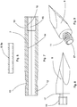
Figure 1 is a longitudinal section of a first embodiment of a microwave device for tissue ablation comprising an antenna provided with a penetrating tip, according to the present invention; -
Figure 2 is a longitudinal section of a second embodiment of a microwave device for tissue ablation comprising an antenna provided with a penetrating tip, according to the present invention; -
Figures 3, 4 and 5 illustrate an example of assembly of the antenna of the microwave device according to the invention; -
Figures 6, 7, 8 and 9 illustrate details of the antenna according to the invention. - In
Figure 1 there is illustrated a first embodiment of an antenna for a microwave device according to the invention. - The antenna 1 comprises a
metal cannula 2 inside which there is arranged aninternal conductor 4, surrounded by alayer 5 of insulating material that is in turn surrounded by anexternal conductor 3 that is coaxial to theinternal conductor 4. Adistal end portion 4a of theinternal conductor 4 protrudes from a distal end of theexternal conductor 3, constituting the radiant end of the antenna 1. - Between the
metal cannula 2 and theexternal conductor 3 of the antenna 1 there is arranged abush 6 in conductive material that is part of a quarter wave impedance transformer, the object of which is to block the reflected microwaves to avoid indiscriminate heating of the tissues surrounding the antenna 1, also at a distance from the portion of tissue directly affected by the coagulative treatment. - The antenna 1 is completed by a penetrating
tip 9 which facilitates the insertion of the antenna through the tissues of a patient until the zone of the body of the patient is reached that has to be subjected to ablation treatment via microwaves. - The penetrating
tip 9 is connected to themetal cannula 2 by a reinforcingelement 7, the object of which is to enable a connection with great mechanical resistance to be made between thepenetrating tip 9 and the antenna 1. The reinforcing element can be made, for example, of zirconium oxide or of ceramic material. The reinforcingelement 7 is provided with aproximal end 7a that can be introduced into thedistal end 12 of themetal cannula 2. Saidproximal end 7a is provided with coupling means 13 that has the object of facilitating coupling between thedistal end 12 of themetal cannula 2 and the reinforcingelement 7. The coupling means may consist of one or more circumferal grooves, as illustrated inFigures 1, 2 ,5 and7 , or of axial incisions, or of spiral incisions, or also of ridges. - The coupling between the
distal end 12 of themetal cannula 2 and theproximal end 7a of the reinforcingelement 7 can be by mechanical crimping, or gluing in the zone of theproximal end 7a where the coupling means 13 is present, i.e. the grooves, incisions or ridges. The coupling between themetal cannula 2 and theproximal end 7a of the reinforcingelement 7 can also be achieved by welding. In this case, however, theproximal end 7a of the reinforcingelement 7 has to be metallised to enable welding to be performed. In all cases, the connection between thecannula 2 and the reinforcingelement 7 ensures great mechanical resistance against detachment of the reinforcingelement 7 from thecannula 2. - The reinforcing
element 7 is provided with anaxial hole 14 that extends over the entire length of the reinforcingelement 7 from theproximal end 7a to adistal end 10. Thedistal end 15 of theaxial hole 14 is provided withinternal threading 16. - The penetrating
tip 9 is provided with ashank 11 provided with anexternal thread 17. Theshank 11 of the penetratingtip 9 can be screwed in thedistal end 15 of theaxial hole 14, thus making a connection with great resistance to traction that greatly reduces the risk of the penetratingtip 9 being able to detach from the antenna 1 because of mechanical stress to which it is subjected during introduction into, and extraction from, the body of a patient. - The antenna 1 is further provided with a
metal bush Figure 4 ) and is inserted into theaxial hole 14 of the reinforcingelement 7, when the latter is coupled with the cannula 2 (Figure 5 ). - In a first embodiment, the
bush 8 has a length that is such as to come into contact with the threadedshank 11 of the penetrating tip 9 (Figure 1 ), thus achieving electrical continuity between the antenna 1 and thepenetrating tip 9. - In a second embodiment, the
bush 8a does not come into contact with the threadedshank 11 of the penetrating tip 9 (Figure 2 ), which enables the operating temperature of the penetratingtip 9 to be reduced. - In the practical embodiment, the materials, dimensions and constructional details can be different from those indicated but be technically equivalent thereto without thereby falling outside the scope of the present invention.
Claims (8)
- Microwave device for tissue ablation comprising an antenna (1), a metal cannula (2) inside which there are arranged an external conductor (3) and an internal conductor (4) of the antenna (1) between which a layer (5) of electrically insulating material is interposed, a penetrating tip (9) connected to the antenna (1), a reinforcing element (7) connected to a distal end (12) of said cannula (2), said penetrating tip (9) being connected to a distal end (10) of said reinforcing element (7), said reinforcing element (7) being provided with an axial hole (14) a distal end (15) of which is provided with internal threading (16), characterised in that it further comprises a bush (8) connected to a distal end of said antenna (1), said bush (8) being inserted into said axial hole (14) and coming into contact with a shank (11) of the penetrating tip (9).
- Device according to claim 1, wherein a proximal end (7a) of said reinforcing element (7) is insertable into said cannula (2) and is provided with connecting means (13) to connect said reinforcing element (7) to said cannula (2).
- Device according to claim 2, wherein said connecting means comprises one or more circumferal grooves (13), or one or more axial incisions, or one or more spiral incisions, or ridges.
- Device (1) according to claim 2, or 3, wherein said reinforcing element (7) is connected to said cannula (2) by crimping or gluing.
- Device (1) according to claim 2, or 3, wherein said reinforcing element (7) is connected to said cannula (2) by welding, said proximal end (7a) being metallised.
- Device (1) according to anyone of claims 2 to 5, wherein said axial hole (14) extends from said proximal end (7a) to a distal end (10) of said reinforcing element (7).
- Device (1) according to claim 6, wherein said shank (11) is provided with an external thread (17).
- Device (1) according to any preceding claim, wherein said reinforcing element (7) is made of zirconium oxide or of a ceramic material.
Applications Claiming Priority (2)
| Application Number | Priority Date | Filing Date | Title |
|---|---|---|---|
| IT000234A ITMO20130234A1 (en) | 2013-08-08 | 2013-08-08 | ANTENNA FOR A MICROWAVE DEVICE FOR FABRIC EXTRACTION |
| PCT/IB2014/063590 WO2015019254A2 (en) | 2013-08-08 | 2014-07-31 | Microwave device for tissue ablation |
Publications (2)
| Publication Number | Publication Date |
|---|---|
| EP3030184A2 EP3030184A2 (en) | 2016-06-15 |
| EP3030184B1 true EP3030184B1 (en) | 2017-02-08 |
Family
ID=49226364
Family Applications (1)
| Application Number | Title | Priority Date | Filing Date |
|---|---|---|---|
| EP14780570.9A Active EP3030184B1 (en) | 2013-08-08 | 2014-07-31 | Microwave device for tissue ablation |
Country Status (9)
| Country | Link |
|---|---|
| US (1) | US9925004B2 (en) |
| EP (1) | EP3030184B1 (en) |
| JP (2) | JP2016528987A (en) |
| KR (1) | KR20160040694A (en) |
| CN (1) | CN105611888B (en) |
| DK (1) | DK3030184T3 (en) |
| ES (1) | ES2624495T3 (en) |
| IT (1) | ITMO20130234A1 (en) |
| WO (1) | WO2015019254A2 (en) |
Families Citing this family (5)
| Publication number | Priority date | Publication date | Assignee | Title |
|---|---|---|---|---|
| CN106618732A (en) * | 2017-01-18 | 2017-05-10 | 南京康友医疗科技有限公司 | Heat condenser |
| WO2021026471A2 (en) | 2019-08-07 | 2021-02-11 | Biocompatibles Uk Limited | Microwave ablation probe |
| CN115605149B (en) * | 2020-03-20 | 2026-03-13 | 波士顿科学医疗设备有限公司 | medical equipment |
| CN113413209B (en) * | 2021-04-29 | 2024-11-08 | 百德(苏州)医疗有限公司 | Assembly method and transmission line structure of semi-flexible microwave ablation antenna |
| USD1084316S1 (en) | 2023-11-20 | 2025-07-15 | Angiodynamics, Inc. | Ferrule |
Family Cites Families (10)
| Publication number | Priority date | Publication date | Assignee | Title |
|---|---|---|---|---|
| JP3497147B2 (en) * | 2001-09-19 | 2004-02-16 | 株式会社エー・イー・ティー・ジャパン | Ultra-small microwave electron source |
| US6878147B2 (en) * | 2001-11-02 | 2005-04-12 | Vivant Medical, Inc. | High-strength microwave antenna assemblies |
| ITMO20050034A1 (en) | 2005-02-11 | 2006-08-12 | Hs Hospital Service Spa | MICROWAVE DEVICE FOR FABRIC APPLICATION. |
| US7799019B2 (en) * | 2005-05-10 | 2010-09-21 | Vivant Medical, Inc. | Reinforced high strength microwave antenna |
| GB2434314B (en) * | 2006-01-03 | 2011-06-15 | Microsulis Ltd | Microwave applicator with dipole antenna |
| US8409187B2 (en) * | 2009-09-08 | 2013-04-02 | Covidien Lp | Microwave antenna probe with high-strength ceramic coupler |
| US8069553B2 (en) * | 2009-09-09 | 2011-12-06 | Vivant Medical, Inc. | Method for constructing a dipole antenna |
| US9375273B2 (en) * | 2009-09-18 | 2016-06-28 | Covidien Lp | System and method for checking high power microwave ablation system status on startup |
| US9993294B2 (en) * | 2009-11-17 | 2018-06-12 | Perseon Corporation | Microwave coagulation applicator and system with fluid injection |
| US8491579B2 (en) * | 2010-02-05 | 2013-07-23 | Covidien Lp | Electrosurgical devices with choke shorted to biological tissue |
-
2013
- 2013-08-08 IT IT000234A patent/ITMO20130234A1/en unknown
-
2014
- 2014-07-31 DK DK14780570.9T patent/DK3030184T3/en active
- 2014-07-31 JP JP2016532771A patent/JP2016528987A/en active Pending
- 2014-07-31 US US14/910,974 patent/US9925004B2/en active Active
- 2014-07-31 KR KR1020167005959A patent/KR20160040694A/en not_active Ceased
- 2014-07-31 ES ES14780570.9T patent/ES2624495T3/en active Active
- 2014-07-31 WO PCT/IB2014/063590 patent/WO2015019254A2/en not_active Ceased
- 2014-07-31 CN CN201480045025.1A patent/CN105611888B/en active Active
- 2014-07-31 EP EP14780570.9A patent/EP3030184B1/en active Active
-
2018
- 2018-12-19 JP JP2018237449A patent/JP6644863B2/en active Active
Non-Patent Citations (1)
| Title |
|---|
| None * |
Also Published As
| Publication number | Publication date |
|---|---|
| CN105611888B (en) | 2018-04-10 |
| WO2015019254A3 (en) | 2015-05-28 |
| JP6644863B2 (en) | 2020-02-12 |
| KR20160040694A (en) | 2016-04-14 |
| US20160199130A1 (en) | 2016-07-14 |
| ES2624495T3 (en) | 2017-07-14 |
| WO2015019254A2 (en) | 2015-02-12 |
| EP3030184A2 (en) | 2016-06-15 |
| ITMO20130234A1 (en) | 2015-02-09 |
| JP2016528987A (en) | 2016-09-23 |
| JP2019069190A (en) | 2019-05-09 |
| DK3030184T3 (en) | 2017-05-15 |
| US9925004B2 (en) | 2018-03-27 |
| CN105611888A (en) | 2016-05-25 |
Similar Documents
| Publication | Publication Date | Title |
|---|---|---|
| EP2819605B1 (en) | Microwave device for tissue ablation | |
| JP6644863B2 (en) | Microwave device for tissue resection | |
| US8608731B2 (en) | Leaky-wave antennas for medical applications | |
| US8679108B2 (en) | Leaky-wave antennas for medical applications | |
| US8512328B2 (en) | Antenna assemblies for medical applications | |
| US9375272B2 (en) | Antenna assemblies for medical applications | |
| CA2636393C (en) | Broadband microwave applicator | |
| HK1200072B (en) | Microwave device for tissue ablation | |
| JP2008054708A (en) | Treatment antenna probe and electromagnetic treatment system |
Legal Events
| Date | Code | Title | Description |
|---|---|---|---|
| PUAI | Public reference made under article 153(3) epc to a published international application that has entered the european phase |
Free format text: ORIGINAL CODE: 0009012 |
|
| 17P | Request for examination filed |
Effective date: 20160226 |
|
| AK | Designated contracting states |
Kind code of ref document: A2 Designated state(s): AL AT BE BG CH CY CZ DE DK EE ES FI FR GB GR HR HU IE IS IT LI LT LU LV MC MK MT NL NO PL PT RO RS SE SI SK SM TR |
|
| AX | Request for extension of the european patent |
Extension state: BA ME |
|
| GRAP | Despatch of communication of intention to grant a patent |
Free format text: ORIGINAL CODE: EPIDOSNIGR1 |
|
| DAX | Request for extension of the european patent (deleted) | ||
| INTG | Intention to grant announced |
Effective date: 20160824 |
|
| GRAS | Grant fee paid |
Free format text: ORIGINAL CODE: EPIDOSNIGR3 |
|
| GRAA | (expected) grant |
Free format text: ORIGINAL CODE: 0009210 |
|
| RIN1 | Information on inventor provided before grant (corrected) |
Inventor name: CASSARINO, SIMONE Inventor name: AMABILE, CLAUDIO Inventor name: IACOBBI, MASSIMILIANO Inventor name: BELLUOMO, ARMANDO Inventor name: TOSORATTI, NEVIO |
|
| AK | Designated contracting states |
Kind code of ref document: B1 Designated state(s): AL AT BE BG CH CY CZ DE DK EE ES FI FR GB GR HR HU IE IS IT LI LT LU LV MC MK MT NL NO PL PT RO RS SE SI SK SM TR |
|
| REG | Reference to a national code |
Ref country code: GB Ref legal event code: FG4D |
|
| REG | Reference to a national code |
Ref country code: CH Ref legal event code: EP Ref country code: AT Ref legal event code: REF Ref document number: 866538 Country of ref document: AT Kind code of ref document: T Effective date: 20170215 |
|
| REG | Reference to a national code |
Ref country code: IE Ref legal event code: FG4D |
|
| REG | Reference to a national code |
Ref country code: DE Ref legal event code: R096 Ref document number: 602014006748 Country of ref document: DE |
|
| REG | Reference to a national code |
Ref country code: DK Ref legal event code: T3 Effective date: 20170510 |
|
| REG | Reference to a national code |
Ref country code: LT Ref legal event code: MG4D |
|
| REG | Reference to a national code |
Ref country code: NL Ref legal event code: MP Effective date: 20170208 |
|
| REG | Reference to a national code |
Ref country code: FR Ref legal event code: PLFP Year of fee payment: 4 |
|
| REG | Reference to a national code |
Ref country code: ES Ref legal event code: FG2A Ref document number: 2624495 Country of ref document: ES Kind code of ref document: T3 Effective date: 20170714 |
|
| REG | Reference to a national code |
Ref country code: AT Ref legal event code: MK05 Ref document number: 866538 Country of ref document: AT Kind code of ref document: T Effective date: 20170208 |
|
| PG25 | Lapsed in a contracting state [announced via postgrant information from national office to epo] |
Ref country code: NO Free format text: LAPSE BECAUSE OF FAILURE TO SUBMIT A TRANSLATION OF THE DESCRIPTION OR TO PAY THE FEE WITHIN THE PRESCRIBED TIME-LIMIT Effective date: 20170508 Ref country code: FI Free format text: LAPSE BECAUSE OF FAILURE TO SUBMIT A TRANSLATION OF THE DESCRIPTION OR TO PAY THE FEE WITHIN THE PRESCRIBED TIME-LIMIT Effective date: 20170208 Ref country code: LT Free format text: LAPSE BECAUSE OF FAILURE TO SUBMIT A TRANSLATION OF THE DESCRIPTION OR TO PAY THE FEE WITHIN THE PRESCRIBED TIME-LIMIT Effective date: 20170208 Ref country code: HR Free format text: LAPSE BECAUSE OF FAILURE TO SUBMIT A TRANSLATION OF THE DESCRIPTION OR TO PAY THE FEE WITHIN THE PRESCRIBED TIME-LIMIT Effective date: 20170208 Ref country code: GR Free format text: LAPSE BECAUSE OF FAILURE TO SUBMIT A TRANSLATION OF THE DESCRIPTION OR TO PAY THE FEE WITHIN THE PRESCRIBED TIME-LIMIT Effective date: 20170509 |
|
| PG25 | Lapsed in a contracting state [announced via postgrant information from national office to epo] |
Ref country code: SE Free format text: LAPSE BECAUSE OF FAILURE TO SUBMIT A TRANSLATION OF THE DESCRIPTION OR TO PAY THE FEE WITHIN THE PRESCRIBED TIME-LIMIT Effective date: 20170208 Ref country code: BG Free format text: LAPSE BECAUSE OF FAILURE TO SUBMIT A TRANSLATION OF THE DESCRIPTION OR TO PAY THE FEE WITHIN THE PRESCRIBED TIME-LIMIT Effective date: 20170508 Ref country code: RS Free format text: LAPSE BECAUSE OF FAILURE TO SUBMIT A TRANSLATION OF THE DESCRIPTION OR TO PAY THE FEE WITHIN THE PRESCRIBED TIME-LIMIT Effective date: 20170208 Ref country code: LV Free format text: LAPSE BECAUSE OF FAILURE TO SUBMIT A TRANSLATION OF THE DESCRIPTION OR TO PAY THE FEE WITHIN THE PRESCRIBED TIME-LIMIT Effective date: 20170208 Ref country code: AT Free format text: LAPSE BECAUSE OF FAILURE TO SUBMIT A TRANSLATION OF THE DESCRIPTION OR TO PAY THE FEE WITHIN THE PRESCRIBED TIME-LIMIT Effective date: 20170208 Ref country code: NL Free format text: LAPSE BECAUSE OF NON-PAYMENT OF DUE FEES Effective date: 20170208 Ref country code: PT Free format text: LAPSE BECAUSE OF FAILURE TO SUBMIT A TRANSLATION OF THE DESCRIPTION OR TO PAY THE FEE WITHIN THE PRESCRIBED TIME-LIMIT Effective date: 20170608 |
|
| PG25 | Lapsed in a contracting state [announced via postgrant information from national office to epo] |
Ref country code: SK Free format text: LAPSE BECAUSE OF FAILURE TO SUBMIT A TRANSLATION OF THE DESCRIPTION OR TO PAY THE FEE WITHIN THE PRESCRIBED TIME-LIMIT Effective date: 20170208 Ref country code: CZ Free format text: LAPSE BECAUSE OF FAILURE TO SUBMIT A TRANSLATION OF THE DESCRIPTION OR TO PAY THE FEE WITHIN THE PRESCRIBED TIME-LIMIT Effective date: 20170208 Ref country code: RO Free format text: LAPSE BECAUSE OF FAILURE TO SUBMIT A TRANSLATION OF THE DESCRIPTION OR TO PAY THE FEE WITHIN THE PRESCRIBED TIME-LIMIT Effective date: 20170208 Ref country code: EE Free format text: LAPSE BECAUSE OF FAILURE TO SUBMIT A TRANSLATION OF THE DESCRIPTION OR TO PAY THE FEE WITHIN THE PRESCRIBED TIME-LIMIT Effective date: 20170208 |
|
| REG | Reference to a national code |
Ref country code: DE Ref legal event code: R097 Ref document number: 602014006748 Country of ref document: DE |
|
| PG25 | Lapsed in a contracting state [announced via postgrant information from national office to epo] |
Ref country code: SM Free format text: LAPSE BECAUSE OF FAILURE TO SUBMIT A TRANSLATION OF THE DESCRIPTION OR TO PAY THE FEE WITHIN THE PRESCRIBED TIME-LIMIT Effective date: 20170208 Ref country code: PL Free format text: LAPSE BECAUSE OF FAILURE TO SUBMIT A TRANSLATION OF THE DESCRIPTION OR TO PAY THE FEE WITHIN THE PRESCRIBED TIME-LIMIT Effective date: 20170208 |
|
| PLBE | No opposition filed within time limit |
Free format text: ORIGINAL CODE: 0009261 |
|
| STAA | Information on the status of an ep patent application or granted ep patent |
Free format text: STATUS: NO OPPOSITION FILED WITHIN TIME LIMIT |
|
| 26N | No opposition filed |
Effective date: 20171109 |
|
| PG25 | Lapsed in a contracting state [announced via postgrant information from national office to epo] |
Ref country code: SI Free format text: LAPSE BECAUSE OF FAILURE TO SUBMIT A TRANSLATION OF THE DESCRIPTION OR TO PAY THE FEE WITHIN THE PRESCRIBED TIME-LIMIT Effective date: 20170208 |
|
| REG | Reference to a national code |
Ref country code: CH Ref legal event code: PL |
|
| PG25 | Lapsed in a contracting state [announced via postgrant information from national office to epo] |
Ref country code: LI Free format text: LAPSE BECAUSE OF NON-PAYMENT OF DUE FEES Effective date: 20170731 Ref country code: CH Free format text: LAPSE BECAUSE OF NON-PAYMENT OF DUE FEES Effective date: 20170731 |
|
| REG | Reference to a national code |
Ref country code: IE Ref legal event code: MM4A |
|
| REG | Reference to a national code |
Ref country code: BE Ref legal event code: MM Effective date: 20170731 |
|
| PG25 | Lapsed in a contracting state [announced via postgrant information from national office to epo] |
Ref country code: LU Free format text: LAPSE BECAUSE OF NON-PAYMENT OF DUE FEES Effective date: 20170731 |
|
| REG | Reference to a national code |
Ref country code: FR Ref legal event code: PLFP Year of fee payment: 5 |
|
| PG25 | Lapsed in a contracting state [announced via postgrant information from national office to epo] |
Ref country code: IE Free format text: LAPSE BECAUSE OF NON-PAYMENT OF DUE FEES Effective date: 20170731 |
|
| PG25 | Lapsed in a contracting state [announced via postgrant information from national office to epo] |
Ref country code: BE Free format text: LAPSE BECAUSE OF NON-PAYMENT OF DUE FEES Effective date: 20170731 |
|
| PG25 | Lapsed in a contracting state [announced via postgrant information from national office to epo] |
Ref country code: MT Free format text: LAPSE BECAUSE OF NON-PAYMENT OF DUE FEES Effective date: 20170731 |
|
| PG25 | Lapsed in a contracting state [announced via postgrant information from national office to epo] |
Ref country code: MC Free format text: LAPSE BECAUSE OF FAILURE TO SUBMIT A TRANSLATION OF THE DESCRIPTION OR TO PAY THE FEE WITHIN THE PRESCRIBED TIME-LIMIT Effective date: 20170208 Ref country code: HU Free format text: LAPSE BECAUSE OF FAILURE TO SUBMIT A TRANSLATION OF THE DESCRIPTION OR TO PAY THE FEE WITHIN THE PRESCRIBED TIME-LIMIT; INVALID AB INITIO Effective date: 20140731 |
|
| PG25 | Lapsed in a contracting state [announced via postgrant information from national office to epo] |
Ref country code: CY Free format text: LAPSE BECAUSE OF FAILURE TO SUBMIT A TRANSLATION OF THE DESCRIPTION OR TO PAY THE FEE WITHIN THE PRESCRIBED TIME-LIMIT Effective date: 20170208 |
|
| PG25 | Lapsed in a contracting state [announced via postgrant information from national office to epo] |
Ref country code: MK Free format text: LAPSE BECAUSE OF FAILURE TO SUBMIT A TRANSLATION OF THE DESCRIPTION OR TO PAY THE FEE WITHIN THE PRESCRIBED TIME-LIMIT Effective date: 20170208 |
|
| PG25 | Lapsed in a contracting state [announced via postgrant information from national office to epo] |
Ref country code: TR Free format text: LAPSE BECAUSE OF FAILURE TO SUBMIT A TRANSLATION OF THE DESCRIPTION OR TO PAY THE FEE WITHIN THE PRESCRIBED TIME-LIMIT Effective date: 20170208 |
|
| PG25 | Lapsed in a contracting state [announced via postgrant information from national office to epo] |
Ref country code: AL Free format text: LAPSE BECAUSE OF FAILURE TO SUBMIT A TRANSLATION OF THE DESCRIPTION OR TO PAY THE FEE WITHIN THE PRESCRIBED TIME-LIMIT Effective date: 20170208 Ref country code: IS Free format text: LAPSE BECAUSE OF FAILURE TO SUBMIT A TRANSLATION OF THE DESCRIPTION OR TO PAY THE FEE WITHIN THE PRESCRIBED TIME-LIMIT Effective date: 20170608 |
|
| PGFP | Annual fee paid to national office [announced via postgrant information from national office to epo] |
Ref country code: ES Payment date: 20250801 Year of fee payment: 12 |
|
| PGFP | Annual fee paid to national office [announced via postgrant information from national office to epo] |
Ref country code: DK Payment date: 20250725 Year of fee payment: 12 Ref country code: DE Payment date: 20250729 Year of fee payment: 12 |
|
| PGFP | Annual fee paid to national office [announced via postgrant information from national office to epo] |
Ref country code: IT Payment date: 20250729 Year of fee payment: 12 |
|
| PGFP | Annual fee paid to national office [announced via postgrant information from national office to epo] |
Ref country code: GB Payment date: 20250728 Year of fee payment: 12 |
|
| PGFP | Annual fee paid to national office [announced via postgrant information from national office to epo] |
Ref country code: FR Payment date: 20250728 Year of fee payment: 12 |