EP3030075B1 - Recovery assembly for cryopreservation applications - Google Patents
Recovery assembly for cryopreservation applications Download PDFInfo
- Publication number
- EP3030075B1 EP3030075B1 EP14747652.7A EP14747652A EP3030075B1 EP 3030075 B1 EP3030075 B1 EP 3030075B1 EP 14747652 A EP14747652 A EP 14747652A EP 3030075 B1 EP3030075 B1 EP 3030075B1
- Authority
- EP
- European Patent Office
- Prior art keywords
- assembly
- funnel
- recovery
- container
- blind
- Prior art date
- Legal status (The legal status is an assumption and is not a legal conclusion. Google has not performed a legal analysis and makes no representation as to the accuracy of the status listed.)
- Not-in-force
Links
- 238000011084 recovery Methods 0.000 title claims description 57
- 238000005138 cryopreservation Methods 0.000 title claims description 21
- 239000002826 coolant Substances 0.000 claims description 32
- 239000007788 liquid Substances 0.000 claims description 18
- 239000000463 material Substances 0.000 claims description 3
- 239000000523 sample Substances 0.000 description 38
- IJGRMHOSHXDMSA-UHFFFAOYSA-N Atomic nitrogen Chemical compound N#N IJGRMHOSHXDMSA-UHFFFAOYSA-N 0.000 description 18
- 238000000605 extraction Methods 0.000 description 15
- 229910052757 nitrogen Inorganic materials 0.000 description 9
- 230000001681 protective effect Effects 0.000 description 6
- 238000001704 evaporation Methods 0.000 description 5
- 230000008020 evaporation Effects 0.000 description 5
- 239000007789 gas Substances 0.000 description 3
- 230000000712 assembly Effects 0.000 description 2
- 238000000429 assembly Methods 0.000 description 2
- 230000015572 biosynthetic process Effects 0.000 description 2
- 238000001816 cooling Methods 0.000 description 2
- 230000001105 regulatory effect Effects 0.000 description 2
- -1 -196 °Celsius Chemical compound 0.000 description 1
- 206010003497 Asphyxia Diseases 0.000 description 1
- 230000009286 beneficial effect Effects 0.000 description 1
- 230000008901 benefit Effects 0.000 description 1
- 239000012620 biological material Substances 0.000 description 1
- 238000011109 contamination Methods 0.000 description 1
- 230000008878 coupling Effects 0.000 description 1
- 238000010168 coupling process Methods 0.000 description 1
- 238000005859 coupling reaction Methods 0.000 description 1
- 230000003247 decreasing effect Effects 0.000 description 1
- 239000003814 drug Substances 0.000 description 1
- 230000002708 enhancing effect Effects 0.000 description 1
- 238000007710 freezing Methods 0.000 description 1
- 230000008014 freezing Effects 0.000 description 1
- 230000035784 germination Effects 0.000 description 1
- 230000036541 health Effects 0.000 description 1
- 238000003780 insertion Methods 0.000 description 1
- 230000037431 insertion Effects 0.000 description 1
- 230000007246 mechanism Effects 0.000 description 1
- 230000004048 modification Effects 0.000 description 1
- 238000012986 modification Methods 0.000 description 1
- 239000002245 particle Substances 0.000 description 1
- 230000002265 prevention Effects 0.000 description 1
- 239000000126 substance Substances 0.000 description 1
- 239000002699 waste material Substances 0.000 description 1
Images

Classifications
-
- A—HUMAN NECESSITIES
- A01—AGRICULTURE; FORESTRY; ANIMAL HUSBANDRY; HUNTING; TRAPPING; FISHING
- A01N—PRESERVATION OF BODIES OF HUMANS OR ANIMALS OR PLANTS OR PARTS THEREOF; BIOCIDES, e.g. AS DISINFECTANTS, AS PESTICIDES OR AS HERBICIDES; PEST REPELLANTS OR ATTRACTANTS; PLANT GROWTH REGULATORS
- A01N1/00—Preservation of bodies of humans or animals, or parts thereof
- A01N1/10—Preservation of living parts
- A01N1/14—Mechanical aspects of preservation; Apparatus or containers therefor
- A01N1/146—Non-refrigerated containers specially adapted for transporting or storing living parts whilst preserving
-
- A—HUMAN NECESSITIES
- A01—AGRICULTURE; FORESTRY; ANIMAL HUSBANDRY; HUNTING; TRAPPING; FISHING
- A01N—PRESERVATION OF BODIES OF HUMANS OR ANIMALS OR PLANTS OR PARTS THEREOF; BIOCIDES, e.g. AS DISINFECTANTS, AS PESTICIDES OR AS HERBICIDES; PEST REPELLANTS OR ATTRACTANTS; PLANT GROWTH REGULATORS
- A01N1/00—Preservation of bodies of humans or animals, or parts thereof
- A01N1/10—Preservation of living parts
- A01N1/14—Mechanical aspects of preservation; Apparatus or containers therefor
-
- A—HUMAN NECESSITIES
- A01—AGRICULTURE; FORESTRY; ANIMAL HUSBANDRY; HUNTING; TRAPPING; FISHING
- A01N—PRESERVATION OF BODIES OF HUMANS OR ANIMALS OR PLANTS OR PARTS THEREOF; BIOCIDES, e.g. AS DISINFECTANTS, AS PESTICIDES OR AS HERBICIDES; PEST REPELLANTS OR ATTRACTANTS; PLANT GROWTH REGULATORS
- A01N1/00—Preservation of bodies of humans or animals, or parts thereof
- A01N1/10—Preservation of living parts
- A01N1/14—Mechanical aspects of preservation; Apparatus or containers therefor
- A01N1/142—Apparatus
- A01N1/144—Apparatus for temperature control, e.g. refrigerators or freeze-drying apparatus
- A01N1/145—Stationary or portable vessels generating cryogenic temperatures, e.g. liquid nitrogen baths
-
- B—PERFORMING OPERATIONS; TRANSPORTING
- B01—PHYSICAL OR CHEMICAL PROCESSES OR APPARATUS IN GENERAL
- B01L—CHEMICAL OR PHYSICAL LABORATORY APPARATUS FOR GENERAL USE
- B01L3/00—Containers or dishes for laboratory use, e.g. laboratory glassware; Droppers
- B01L3/56—Labware specially adapted for transferring fluids
-
- B—PERFORMING OPERATIONS; TRANSPORTING
- B01—PHYSICAL OR CHEMICAL PROCESSES OR APPARATUS IN GENERAL
- B01L—CHEMICAL OR PHYSICAL LABORATORY APPARATUS FOR GENERAL USE
- B01L2200/00—Solutions for specific problems relating to chemical or physical laboratory apparatus
- B01L2200/02—Adapting objects or devices to another
- B01L2200/023—Adapting objects or devices to another adapted for different sizes of tubes, tips or container
-
- B—PERFORMING OPERATIONS; TRANSPORTING
- B01—PHYSICAL OR CHEMICAL PROCESSES OR APPARATUS IN GENERAL
- B01L—CHEMICAL OR PHYSICAL LABORATORY APPARATUS FOR GENERAL USE
- B01L2200/00—Solutions for specific problems relating to chemical or physical laboratory apparatus
- B01L2200/02—Adapting objects or devices to another
- B01L2200/025—Align devices or objects to ensure defined positions relative to each other
-
- B—PERFORMING OPERATIONS; TRANSPORTING
- B01—PHYSICAL OR CHEMICAL PROCESSES OR APPARATUS IN GENERAL
- B01L—CHEMICAL OR PHYSICAL LABORATORY APPARATUS FOR GENERAL USE
- B01L2200/00—Solutions for specific problems relating to chemical or physical laboratory apparatus
- B01L2200/02—Adapting objects or devices to another
- B01L2200/028—Modular arrangements
-
- B—PERFORMING OPERATIONS; TRANSPORTING
- B01—PHYSICAL OR CHEMICAL PROCESSES OR APPARATUS IN GENERAL
- B01L—CHEMICAL OR PHYSICAL LABORATORY APPARATUS FOR GENERAL USE
- B01L2200/00—Solutions for specific problems relating to chemical or physical laboratory apparatus
- B01L2200/06—Fluid handling related problems
- B01L2200/0615—Loss of fluid by dripping
-
- B—PERFORMING OPERATIONS; TRANSPORTING
- B01—PHYSICAL OR CHEMICAL PROCESSES OR APPARATUS IN GENERAL
- B01L—CHEMICAL OR PHYSICAL LABORATORY APPARATUS FOR GENERAL USE
- B01L2300/00—Additional constructional details
- B01L2300/06—Auxiliary integrated devices, integrated components
- B01L2300/0609—Holders integrated in container to position an object
-
- B—PERFORMING OPERATIONS; TRANSPORTING
- B01—PHYSICAL OR CHEMICAL PROCESSES OR APPARATUS IN GENERAL
- B01L—CHEMICAL OR PHYSICAL LABORATORY APPARATUS FOR GENERAL USE
- B01L2300/00—Additional constructional details
- B01L2300/18—Means for temperature control
- B01L2300/1883—Means for temperature control using thermal insulation
Definitions
- the present invention relates to a recovery assembly and to a cryopreservation device for reducing consumption and losses of a cooling agent usable for cryopreservation of cryosamples.
- the invention therefore relates to an assembly and to a respective device for treating or examining of cryosamples and well as for inserting or extracting of cryosamples to and from a sample container. Freezing of samples of e.g. biological material while maintaining the vitality of the sample material at temperatures of liquid nitrogen, i.e. -196 °Celsius, is widely known in the areas of biology, pharmacology, medicine and biotechnology. Samples to be frozen and being designated as cryosamples are customarily stored and transferred in sample containers. Such sample containers, also denoted as cryotanks are typically filled with liquid nitrogen. Furthermore, such containers are thermally insulated and may resemble or comprise a so called Dewar vessel.
- Insertion and extraction or removal of samples into and from such containers is sometimes critical. Especially when removing or extracting a sample from a filled sample container, a non-negligible amount of nitrogen may be spilled or may otherwise leave the container in a rather uncontrolled way. It is not only, that the cooling agent is spilled or wasted but that the surrounding air becomes enriched with gaseous nitrogen. Hence, there may further evolve a certain risk of health or of suffocating.
- Document US 2006/0156753 A1 relates to the aspect of preventing a contact of the surrounding and relatively moist air when handling samples and/or sample containers. There, prevention of ice formation on the sample containers and/or samples and their germination is prevented in various ways. It is suggested to provide a protective container that receives the sample and/or the entire sample container during the handling. Moreover, a climate control equipment is provided which is connected to the protective container in order to dry and cool the ambient gas present in the protective container and/or replace it with the protective gas. Hence, an artificial atmosphere is preferably created in the protective container to prevent ice formation on the sample and/or sample container. Complexity of the technical equipment to provide such a protective atmosphere is rather high as well as cost intensive.
- a recovery assembly for a cryopreservation device comprises a cone-shaped funnel assembly with a support.
- the recovery assembly is particularly adapted and operable to recover a cooling agent of the cryopreservation device.
- the funnel assembly and hence the entire recovery assembly can be mounted on or to an access opening of a container, typically of a cryopreservation container or sample container at least partially to be filled with a cooling agent, e.g. liquid nitrogen.
- the container may comprise a Dewar vessel being open to the top in order to allow permanent evaporation cooling of the liquid cooling agent disposed therein.
- the recovery assembly is adapted to be mounted to the upper access opening of the container for recovery of the cooling agent, especially when extracting a sample from the container.
- the recovery assembly further comprises at least one cone-shaped funnel portion converging towards the support.
- the recovery assembly may comprise a funnel of e.g. circular-shape or circular cross section extending in a diverging way from the support.
- excess cooling agent which in the course of extraction of a cryosample may drip or rinse down from a sample or from a respective specimen holder can be collected and fed back into the container in a controlled way.
- the recovery assembly helps to save and to reduce consumption of a cooling agent and allows for an easy and efficient draining of the cooling agent back into the sample container in the event of extraction or removal of a specimen holder therefrom which is equipped with one or several cryosamples.
- the funnel assembly further comprises a blind assembly extending across the inner cross-section of the funnel assembly.
- a blind assembly By means of the blind assembly, the effective size of an access opening or through opening of the funnel assembly can be modified in order to decrease or increase the size of the through opening. This way, a thermal exchange with the environment and hence a rate of evaporation of the cooling agent can be regulated.
- a vapor penetrable closure can be provided for the sample container. This way, the access opening of the container can be effectively protected against ingress of external substances, particles or items, which may otherwise accidentally enter the probe container.
- the blind assembly does not hinder evaporation cooling of the cooling agent.
- variable blind assembly By means of the variable blind assembly the safety for operational staff working with the cooling agent can be increased. Moreover, by means of the blind assembly the amount of gaseous cooling agent and the amount of liquid cooling agent in the surrounding environment can be kept on a comparatively low level. This way, a risk of burning and suffocation for an operator can be advantageously reduced.
- the support of the recovery assembly is adapted to receive an upper neck portion and/or an upper rim of the container.
- the container which typically comprises a Dewar vessel may be cone-shaped towards it upper, distal end. This way, an upper rim or an upper end of said container may be received in the support of the recovery assembly, which may be integrally formed with the recovery assembly's funnel assembly.
- the support may coincide with a lower edge of the funnel assembly, hence a lower edge of a cone-shaped sidewall portion of the funnel assemble may form the support.
- the support of the recovery assembly and the upper neck portion of the sample container are correspondingly shaped so as to allow a well defined mutual and releasable assembly of recovery assembly and sample container.
- the support to be mounted to the access opening of the container is preferably mechanically engageable with said container.
- the support and the access opening comprise a fastening, typically in form of mutually engaging fixing means, such like positive engaging locking means, a bayonet cap, a screw connection or mutually engaging bolts and recesses. This way, a reliable and durable mutual fastening and interconnection of the recovery assembly and the sample container can be established.
- the blind assembly provides and comprises a through opening, which when assembled to the sample container substantially flushes with the access opening of said container.
- the through opening of the blind assembly is of variable size and is modifiable by an operator on demand. If the operator intends to extract or to store a specimen holder or a cryosample from or into the sample container, the through opening of the blind assembly can be at least temporarily increased. In a storage mode, wherein the at least one specimen holder together with numerous cryosamples is only to be kept and immersed in the liquid cooling agent, the size of the blind assembly's through opening can be reduced to a minimum in order to reduce evaporation and escapement of the cooling agent.
- the blind assembly comprises an iris blind to modify the size of its through opening.
- iris blind mechanisms are widely distributed and are commercially available, e.g. in the field of optics.
- the blind assembly in particular the iris blind assembly is integrated into the funnel assembly of the recovery assembly.
- an actuation member operable to modify the size of the iris blind's through opening is accessible from outside the funnel assembly.
- the actuation member extends radially outwardly from the funnel assembly.
- the iris blind assembly is preferably arranged gas and/or liquid tight in the funnel assembly so that liquid cooling agent, which may eventually rinse down the inner sidewall of the funnel assembly is effectively hindered to leak through the iris blind assembly.
- the funnel assembly comprises at least one outwardly extending recess at an inside wall portion, preferably located above the blind assembly, to receive and to support a specimen holder in an inclined orientation above the blind's through opening.
- the recess may comprise a slanted or inclined bottom portion in order to support the lifted specimen holder in the inclined orientation.
- the funnel assembly further comprises an additional support extending from an upper end thereof obliquely opposite to the outwardly extending recess.
- the additional support is either displaceably or pivotably mounted at the upper edge of the funnel assembly. This way, the support can be oriented and positioned in a specimen-supporting configuration on demand. If not used or required the support can for instance be pivoted inwardly to but against the inner sidewall of the funnel assembly. Alternatively, the support may also be pivoted outwardly or may even be disconnected or dismounted from the funnel assembly.
- the additional support may at least partially extend radially inwardly into the funnel assembly in order to provide a holding means and a holder for the inclined oriented specimen holder provided in the recess.
- the funnel assembly comprises a thermally insulated material and/or a thermally insulating structure.
- the funnel assembly is of non-thermoconducting material. In this way, operational safety of the recovery assembly can be further increased. Touching or handling of the funnel assembly may not harm the skin of an operator. Hence, the risk of burning can be substantially reduced.
- the recovery assembly is releasably attachable to the sample container.
- the support of the recovery assembly and the access opening of the sample container are releasably engageable.
- the recovery assembly may be arbitrarily used with a large variety of sample containers. While cryosamples are stored in a specific container, the recovery assembly may be disassembled and may be used with other sample containers at least for extracting samples therefrom. Therefore, a single recovery assembly may be efficiently used with several sample containers.
- the blind assembly further comprises an annular frame and multiple radially displaceable segments extending in the plane of the frame.
- the segments are typically displaceable in radial and eventually also in tangential or circumferential direction in order to modify or to vary the size of the blind's through opening.
- the size of the blind's through opening can be reduced to such an extend that the through opening's cross section or diameter is smaller than the outer dimensions of the specimen holder.
- the substantially closed blind may even serve as a support structure for a lifted specimen holder.
- the segments of an iris blind provide a sufficient mechanical stability the lifted specimen holder can be put onto the substantially closed blind.
- the at least one, preferably two oppositely located and radially inwardly pivoted additional supports extending radially inwardly from the upper edge of the funnel assembly are of advantage to keep the specimen holder in an upright orientation when standing on the closed blind.
- the invention also relates to a cryopreservation device, which is adapted to store at least one specimen, in particular a cryosample.
- the cryopreservation device comprises a container to accommodate a liquid cooling agent, such as liquid nitrogen. Said container further comprises an access opening at a distal upper end.
- the cryopreservation device comprises and is equipped with a recovery assembly as described above.
- the recovery assembly is mounted on the access opening via its support or may be simply operable to be mounted to said access opening.
- the recovery assembly is removably mounted on the access opening, preferably in a releasable and reconfigurable way. This allows to arbitrarily couple the recovery assembly with a variety of sample containers whenever specimens or cryosamples have to be put into or taken from the container.
- the recovery assembly also comprises an extraction assembly at least for extracting a specimen, e.g. a cryosample from the container through the access opening.
- the extraction assembly of the recovery assembly is particularly adapted to grip and to raise at least one specimen out of the cooling agent and upwards through the access opening of the sample container.
- the recovery assembly and the extraction assembly may either be releasably coupled or may be integrally formed. With a releasable coupling of recovery assembly and extraction assembly, the recovery assembly may be used with other, e.g. stationary and immobile extraction assemblies, which may for instance be mounted to a ceiling of a room. With an integrated arrangement of recovery assembly and extraction assembly, mounting of the recovery assembly on the access opening of the sample container immediately provides an appropriate position of the extraction assembly relative to the sample container. This way, a separate positioning and configuration of the extraction assembly is not required.
- the extraction assembly may comprise at least one pillar or a similar support structure extending through the recovery assembly's funnel portion to support a pulling device located above an upper end of the funnel portion.
- the pulling device may comprise a flexible strap or a chain, by means of which the at least one specimen located in the sample container can be gripped and lifted out of the sample container.
- the cryopreservation device 10 as shown in Figs. 1 and 2 comprises a sample or storage container 16 typically designed as a Dewar vessel.
- the storage container 16 comprises a Dewar wall structure 14 which is substantially non-thermoconducting. Hence, the surrounding walls of the storage container 16 are thermally insulated.
- the storage container 16 comprises a converging neck portion 30, which may resemble a bottleneck. At its upper end, the neck portion 30 comprises an annular rim 28, which in the embodiment according to Fig. 1 and 2 serves to engage with a hook 26 of a hanger 24 interconnected with a specimen holder 18.
- the specimen holder 18 comprises numerous compartments or containers 20 to receive various cryosamples. In storage mode as illustrated in Fig. 1 , the specimen holder 18 is intended to be completely immersed in the liquid cooling agent 12, typically comprising liquid nitrogen at -196 °Celsius.
- the cryopreservation device 10 is further equipped with a funnel assembly 32 comprising a cone-shaped funnel 34 which is to be assembled on top of an access opening of the neck portion 30 of the storage container 16.
- the funnel 34 comprises a support 40 with a lower edge 42 which may frictionally engage with the neck portion 30 of the storage container 16.
- the lower portion of the funnel 34 therefore provides a support structure 40 by way of which the funnel assembly 32 can be mounted on the storage container 16 in a well-defined way.
- the support structure 40 and the neck portion 30 may comprise a mutually corresponding fastening, e.g. in form of positive engaging locking means, such like a bayonet fixing, a screw connection or by means of mutually corresponding recesses and bolts or pins.
- raised and lifted specimen holders 18 can be oriented in an inclined way as illustrated in Fig. 2 , thereby allowing to feed back excess cooling agent 12' into the storage container 16. Since the funnel 34 radially widens and radially diverges in an upward direction, liquid cooling agent 12 which may rinse down from the lifted specimen holder 18 can be collected over a comparatively large area compared to the size of the sample containers 16 access opening.
- the funnel 34 also comprises radially outwardly extending notches or recesses 38 extending from an inner wall of the funnel 34.
- the recesses 38 comprise a slanted or inclined bottom portion 46 and a respective sidewall portion 44.
- the recesses 34 are operable to support a lifted specimen holder 18 in an inclined orientation above the blind assembly's 36 through opening 52.
- the recovery assembly can be provided with an additional support 49, which is for instance pivotally arranged by means of a hinge at an upper end or upper rim 48 of the funnel 34.
- Such an additional support may be folded to extend at least partially radially inwardly in order to support, to hold and to stabilize the specimen holder 18 in an inclined orientation when leaned against the radially inwardly pivoted support.
- the support 49 can either be pivoted radially inwardly to abut against an inside wall of the funnel assembly 32.
- the support 49 may be pivoted radially outwardly for not obstructing the inside wall of the funnel assembly 32.
- the support 49 may be detachably or removably arranged at the upper rim 48.
- the funnel assembly 32 further comprises an iris blind assembly 36 arranged above a lower edge 42 of the funnel 34 and extending across the entire funnel 34.
- the iris blind assembly 36 comprises an annular frame 50 and various iris segments 54 radially inwardly extending therefrom.
- the various iris segments 54 are radially and/or tangentially displaceable between at least two extreme configurations as shown in Fig. 3 and Fig. 4 .
- the various iris segments 54 are further operably connected and engaged with an actuation member 56 extending radially outwardly from the frame 50.
- an actuation member 56 By twisting or displacing the actuation member 56 from e.g. a 1 o'clock configuration as shown in Fig. 3 towards an 11 o'clock configuration as shown in Fig. 4 , the various iris segments 54 can be simultaneously displaced radially outwardly in order to increase the size of the through opening 52 towards a maximum increased configuration as indicated in Fig. 4 with 52'.
- the actuation member 56 of the iris blind assembly 36 preferably protrudes from the funnel 34 radially outwardly.
- the various iris segments 54 are not separately illustrated in the sketch of Fig. 2 .
- the rate of evaporation of the liquid cooling agent 12 can be regulated and can be decreased. This way, contamination of the environment with evaporated or liquid cooling agent 12 can be reduced to a minimum, thereby enhancing operational safety and reducing the risk of burning or suffocating.
- the funnel 34 also comprises radially outwardly extending notches or recesses 38 extending from an inner wall of the funnel 34.
- the recesses 38 comprise a slanted or inclined bottom portion 46 and a respective sidewall portion 44.
- the recesses 38 are operable to support a lifted specimen holder 18 in an inclined orientation above the blind assembly's 36 through opening 52.
- the pivotable or removable support 49 is of particular use to keep a lifted specimen holder 18 in the inclined orientation.
- the lifted specimen holder 18 onto the closed iris blind assembly 36.
- the specimen holder may be lifted out of the storage container 16 when the iris blind is in an opened configuration. Thereafter the size of the through opening 52 of the iris blind assembly 36 can be reduced to such an extend that the diameter of the remaining through opening 52 is smaller than the cross section of the specimen holder 18. Then the specimen holder 18 can be positioned onto the segments of the iris blind assembly 36.
- the at least one support 49 or several supports 49 are operable to keep the specimen holder 18 in a stable orientation, e.g. in an upright or inclined configuration.
- excess cooling agent may drop or rinse down from various cryosample compartments 20 of the specimen holder 18 as shown in Fig. 2 in form of various drops 12'.
- the recovery assembly may be provided with an additional support, e.g. pivotally arranged by means of a hinge at an upper end or upper rim 48 of the funnel 34.
- Such a support may be folded to extend at least partially radially inwardly in order to support, to hold and to stabilize the specimen holder 18 in an inclined orientation when leaned against the radially inwardly pivoted support.
- Lifting of the specimen holder out of the storage container 16 can be provided either manually, e.g. by gripping the hanger 24 or hook 26 with the hands of operating personal.
- an extraction assembly 60 can be provided, e.g. comprising a pulley 62 that serves as a deflection wheel for a chain 64 or for a comparable flexible strap.
- the chain may comprise a hook 68 to engage with a corresponding hook 26 provided at the upper end of the specimen holder 18.
- the pulley 62 is mounted on a ceiling 66.
- the specimen or specimen holder 18 can be lifted and can be raised above a level of an upper edge 48 of the funnel assembly 32.
- the pulley may be releasably mounted and fixed to the funnel assembly, e.g. by means of at least one, preferably two or three circumferentially distributed pillars extending upwardly from the funnel assembly in order to provide a support for the pulley 62.
Landscapes
- Life Sciences & Earth Sciences (AREA)
- Health & Medical Sciences (AREA)
- Engineering & Computer Science (AREA)
- Dentistry (AREA)
- General Health & Medical Sciences (AREA)
- Wood Science & Technology (AREA)
- Zoology (AREA)
- Environmental Sciences (AREA)
- Clinical Laboratory Science (AREA)
- Chemical & Material Sciences (AREA)
- Chemical Kinetics & Catalysis (AREA)
- Sampling And Sample Adjustment (AREA)
- Agricultural Chemicals And Associated Chemicals (AREA)
- Medical Preparation Storing Or Oral Administration Devices (AREA)
- Hematology (AREA)
- Mechanical Engineering (AREA)
Description
- The present invention relates to a recovery assembly and to a cryopreservation device for reducing consumption and losses of a cooling agent usable for cryopreservation of cryosamples. The invention therefore relates to an assembly and to a respective device for treating or examining of cryosamples and well as for inserting or extracting of cryosamples to and from a sample container. Freezing of samples of e.g. biological material while maintaining the vitality of the sample material at temperatures of liquid nitrogen, i.e. -196 °Celsius, is widely known in the areas of biology, pharmacology, medicine and biotechnology. Samples to be frozen and being designated as cryosamples are customarily stored and transferred in sample containers. Such sample containers, also denoted as cryotanks are typically filled with liquid nitrogen. Furthermore, such containers are thermally insulated and may resemble or comprise a so called Dewar vessel.
- Insertion and extraction or removal of samples into and from such containers is sometimes critical. Especially when removing or extracting a sample from a filled sample container, a non-negligible amount of nitrogen may be spilled or may otherwise leave the container in a rather uncontrolled way. It is not only, that the cooling agent is spilled or wasted but that the surrounding air becomes enriched with gaseous nitrogen. Hence, there may further evolve a certain risk of health or of suffocating.
- Document
US 2006/0156753 A1 relates to the aspect of preventing a contact of the surrounding and relatively moist air when handling samples and/or sample containers. There, prevention of ice formation on the sample containers and/or samples and their germination is prevented in various ways. It is suggested to provide a protective container that receives the sample and/or the entire sample container during the handling. Moreover, a climate control equipment is provided which is connected to the protective container in order to dry and cool the ambient gas present in the protective container and/or replace it with the protective gas. Hence, an artificial atmosphere is preferably created in the protective container to prevent ice formation on the sample and/or sample container. Complexity of the technical equipment to provide such a protective atmosphere is rather high as well as cost intensive. - From Anonymous "Handling, Transport and Storage of Cryogens", Department of Chemistry - Guidelines (University of Wollongong), 5. September 2007 XP055096818 it is known to make use of a filling funnel when pouring liquid nitrogen into a dewar or small container. Document
WO 02/053967 A1 - It is therefore an object of the present invention to provide an improved cryopreservation device together with a recovery assembly for reducing and preventing uncontrolled escapement of the cooling agent. Moreover, consumption and waste of the cooling agent should be kept on a low or at least moderate level. It is a further aim to enhance operational safety of such devices and to protect operative staff against uncontrolled and vast exposure to the cooling agent, e.g. liquid nitrogen.
- The invention is defined in the claims.
- In a first aspect, a recovery assembly for a cryopreservation device is provided. The recovery assembly comprises a cone-shaped funnel assembly with a support. The recovery assembly is particularly adapted and operable to recover a cooling agent of the cryopreservation device. By means of the support the funnel assembly and hence the entire recovery assembly can be mounted on or to an access opening of a container, typically of a cryopreservation container or sample container at least partially to be filled with a cooling agent, e.g. liquid nitrogen. The container may comprise a Dewar vessel being open to the top in order to allow permanent evaporation cooling of the liquid cooling agent disposed therein. The recovery assembly is adapted to be mounted to the upper access opening of the container for recovery of the cooling agent, especially when extracting a sample from the container.
- The recovery assembly further comprises at least one cone-shaped funnel portion converging towards the support. Hence, the recovery assembly may comprise a funnel of e.g. circular-shape or circular cross section extending in a diverging way from the support. By means of the cone-shaped funnel portion, excess cooling agent, which in the course of extraction of a cryosample may drip or rinse down from a sample or from a respective specimen holder can be collected and fed back into the container in a controlled way.
- In this way, the recovery assembly helps to save and to reduce consumption of a cooling agent and allows for an easy and efficient draining of the cooling agent back into the sample container in the event of extraction or removal of a specimen holder therefrom which is equipped with one or several cryosamples.
- The funnel assembly further comprises a blind assembly extending across the inner cross-section of the funnel assembly. By means of the blind assembly, the effective size of an access opening or through opening of the funnel assembly can be modified in order to decrease or increase the size of the through opening. This way, a thermal exchange with the environment and hence a rate of evaporation of the cooling agent can be regulated. Moreover, by means of the blind assembly a vapor penetrable closure can be provided for the sample container. This way, the access opening of the container can be effectively protected against ingress of external substances, particles or items, which may otherwise accidentally enter the probe container. At the same time, the blind assembly does not hinder evaporation cooling of the cooling agent.
- By means of the variable blind assembly the safety for operational staff working with the cooling agent can be increased. Moreover, by means of the blind assembly the amount of gaseous cooling agent and the amount of liquid cooling agent in the surrounding environment can be kept on a comparatively low level. This way, a risk of burning and suffocation for an operator can be advantageously reduced.
- In a preferred embodiment, the support of the recovery assembly is adapted to receive an upper neck portion and/or an upper rim of the container. The container which typically comprises a Dewar vessel may be cone-shaped towards it upper, distal end. This way, an upper rim or an upper end of said container may be received in the support of the recovery assembly, which may be integrally formed with the recovery assembly's funnel assembly. In a rather basic embodiment, the support may coincide with a lower edge of the funnel assembly, hence a lower edge of a cone-shaped sidewall portion of the funnel assemble may form the support.
- Preferably, the support of the recovery assembly and the upper neck portion of the sample container are correspondingly shaped so as to allow a well defined mutual and releasable assembly of recovery assembly and sample container.
- The support to be mounted to the access opening of the container is preferably mechanically engageable with said container. In particular, the support and the access opening comprise a fastening, typically in form of mutually engaging fixing means, such like positive engaging locking means, a bayonet cap, a screw connection or mutually engaging bolts and recesses. This way, a reliable and durable mutual fastening and interconnection of the recovery assembly and the sample container can be established.
- In a further preferred embodiment the blind assembly provides and comprises a through opening, which when assembled to the sample container substantially flushes with the access opening of said container. The through opening of the blind assembly is of variable size and is
modifiable by an operator on demand. If the operator intends to extract or to store a specimen holder or a cryosample from or into the sample container, the through opening of the blind assembly can be at least temporarily increased. In a storage mode, wherein the at least one specimen holder together with numerous cryosamples is only to be kept and immersed in the liquid cooling agent, the size of the blind assembly's through opening can be reduced to a minimum in order to reduce evaporation and escapement of the cooling agent. - In a further preferred embodiment the blind assembly comprises an iris blind to modify the size of its through opening. Moreover, iris blind mechanisms are widely distributed and are commercially available, e.g. in the field of optics.
- In a further preferred embodiment, the blind assembly, in particular the iris blind assembly is integrated into the funnel assembly of the recovery assembly. Preferably, an actuation member operable to modify the size of the iris blind's through opening is accessible from outside the funnel assembly. In particular, the actuation member extends radially outwardly from the funnel assembly. With this integral embodiment, the iris blind assembly is preferably arranged gas and/or liquid tight in the funnel assembly so that liquid cooling agent, which may eventually rinse down the inner sidewall of the funnel assembly is effectively hindered to leak through the iris blind assembly.
- In a further preferred embodiment the funnel assembly comprises at least one outwardly extending recess at an inside wall portion, preferably located above the blind assembly, to receive and to support a specimen holder in an inclined orientation above the blind's through opening. The recess may comprise a slanted or inclined bottom portion in order to support the lifted specimen holder in the inclined orientation.
- According to another embodiment the funnel assembly further comprises an additional support extending from an upper end thereof obliquely opposite to the outwardly extending recess. This way, a lifted specimen holder can be kept in supported and in an inclined orientation above an orifice of the support and/or above the blind assembly. The additional support is either displaceably or pivotably mounted at the upper edge of the funnel assembly. This way, the support can be oriented and positioned in a specimen-supporting configuration on demand. If not used or required the support can for instance be pivoted inwardly to but against the inner sidewall of the funnel assembly. Alternatively, the support may also be pivoted outwardly or may even be disconnected or dismounted from the funnel assembly.
- The additional support may at least partially extend radially inwardly into the funnel assembly in order to provide a holding means and a holder for the inclined oriented specimen holder provided in the recess.
- In a further preferred embodiment, the funnel assembly comprises a thermally insulated material and/or a thermally insulating structure. Hence, the funnel assembly is of non-thermoconducting material. In this way, operational safety of the recovery assembly can be further increased. Touching or handling of the funnel assembly may not harm the skin of an operator. Hence, the risk of burning can be substantially reduced.
- In a further preferred embodiment, the recovery assembly is releasably attachable to the sample container. In particular, the support of the recovery assembly and the access opening of the sample container are releasably engageable. This way, the recovery assembly may be arbitrarily used with a large variety of sample containers. While cryosamples are stored in a specific container, the recovery assembly may be disassembled and may be used with other sample containers at least for extracting samples therefrom. Therefore, a single recovery assembly may be efficiently used with several sample containers. Here, it is beneficial when the recovery assembly and the sample container comprise or form a standardized mutual fastening to enable universal exchange of sample containers and recovery assemblies.
- In still another embodiment the blind assembly further comprises an annular frame and multiple radially displaceable segments extending in the plane of the frame. The segments are typically displaceable in radial and eventually also in tangential or circumferential direction in order to modify or to vary the size of the blind's through opening.
- It is even conceivable that the size of the blind's through opening can be reduced to such an extend that the through opening's cross section or diameter is smaller than the outer dimensions of the specimen holder. In this way, the substantially closed blind may even serve as a support structure for a lifted specimen holder. Especially when the segments of an iris blind provide a sufficient mechanical stability the lifted specimen holder can be put onto the substantially closed blind.
- In such a configuration the at least one, preferably two oppositely located and radially inwardly pivoted additional supports extending radially inwardly from the upper edge of the funnel assembly are of advantage to keep the specimen holder in an upright orientation when standing on the closed blind.
- In still another aspect the invention also relates to a cryopreservation device, which is adapted to store at least one specimen, in particular a cryosample. The cryopreservation device comprises a container to accommodate a liquid cooling agent, such as liquid nitrogen. Said container further comprises an access opening at a distal upper end. Moreover, the cryopreservation device comprises and is equipped with a recovery assembly as described above. Here, the recovery assembly is mounted on the access opening via its support or may be simply operable to be mounted to said access opening.
- In a further and preferred embodiment, the recovery assembly is removably mounted on the access opening, preferably in a releasable and reconfigurable way. This allows to arbitrarily couple the recovery assembly with a variety of sample containers whenever specimens or cryosamples have to be put into or taken from the container.
- According to a further embodiment, not forming part of the present invention, the recovery assembly also comprises an extraction assembly at least for extracting a specimen, e.g. a cryosample from the container through the access opening. The extraction assembly of the recovery assembly is particularly adapted to grip and to raise at least one specimen out of the cooling agent and upwards through the access opening of the sample container.
- The recovery assembly and the extraction assembly may either be releasably coupled or may be integrally formed. With a releasable coupling of recovery assembly and extraction assembly, the recovery assembly may be used with other, e.g. stationary and immobile extraction assemblies, which may for instance be mounted to a ceiling of a room. With an integrated arrangement of recovery assembly and extraction assembly, mounting of the recovery assembly on the access opening of the sample container immediately provides an appropriate position of the extraction assembly relative to the sample container. This way, a separate positioning and configuration of the extraction assembly is not required.
- In a further embodiment, wherein the extraction assembly is attached to the recovery assembly, the extraction assembly may comprise at least one pillar or a similar support structure extending through the recovery assembly's funnel portion to support a pulling device located above an upper end of the funnel portion. The pulling device may comprise a flexible strap or a chain, by means of which the at least one specimen located in the sample container can be gripped and lifted out of the sample container.
- It will be further apparent to those skilled in the pertinent art that various modifications and variations can be made to the present invention without departing from the spirit and scope of the invention. Further, it is to be noted, that any reference signs used in the appended claims are not to be construed as limiting the scope of the present invention.
- In the following, preferred embodiments of the invention will be described in greater detail by making reference to the drawings, in which:
- Figure 1
- schematically illustrates a cryopreservation device equipped with a recovery assembly in a storage configuration,
- Figure 2
- shows the device according to
Fig. 1 with a specimen holder extracted from the device, - Figure 3
- schematically shows the iris blind assembly in a substantially closed configuration and
- Figure 4
- shows the iris blind assembly in a substantially open configuration.
- The
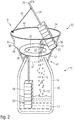
cryopreservation device 10 as shown inFigs. 1 and2 comprises a sample orstorage container 16 typically designed as a Dewar vessel. Thestorage container 16 comprises aDewar wall structure 14 which is substantially non-thermoconducting. Hence, the surrounding walls of thestorage container 16 are thermally insulated. - The
storage container 16 comprises a convergingneck portion 30, which may resemble a bottleneck. At its upper end, theneck portion 30 comprises anannular rim 28, which in the embodiment according toFig. 1 and2 serves to engage with ahook 26 of ahanger 24 interconnected with aspecimen holder 18. Thespecimen holder 18 comprises numerous compartments orcontainers 20 to receive various cryosamples. In storage mode as illustrated inFig. 1 , thespecimen holder 18 is intended to be completely immersed in theliquid cooling agent 12, typically comprising liquid nitrogen at -196 °Celsius. - The
cryopreservation device 10 is further equipped with afunnel assembly 32 comprising a cone-shapedfunnel 34 which is to be assembled on top of an access opening of theneck portion 30 of thestorage container 16. Thefunnel 34 comprises asupport 40 with alower edge 42 which may frictionally engage with theneck portion 30 of thestorage container 16. The lower portion of thefunnel 34 therefore provides asupport structure 40 by way of which thefunnel assembly 32 can be mounted on thestorage container 16 in a well-defined way. - As indicated by
reference numeral 41, thesupport structure 40 and theneck portion 30 may comprise a mutually corresponding fastening, e.g. in form of positive engaging locking means, such like a bayonet fixing, a screw connection or by means of mutually corresponding recesses and bolts or pins. - By means of the
funnel assembly 32, raised and liftedspecimen holders 18 can be oriented in an inclined way as illustrated inFig. 2 , thereby allowing to feed back excess cooling agent 12' into thestorage container 16. Since thefunnel 34 radially widens and radially diverges in an upward direction,liquid cooling agent 12 which may rinse down from the liftedspecimen holder 18 can be collected over a comparatively large area compared to the size of thesample containers 16 access opening. - Furthermore and as illustrated in
Figs. 1 and2 , thefunnel 34 also comprises radially outwardly extending notches or recesses 38 extending from an inner wall of thefunnel 34. As shown inFig. 2 therecesses 38 comprise a slanted orinclined bottom portion 46 and arespective sidewall portion 44. By means of theinclined bottom portion 46, therecesses 34 are operable to support a liftedspecimen holder 18 in an inclined orientation above the blind assembly's 36 throughopening 52. - When kept in an inclined orientation, excess cooling agent may drop or rinse down from various cryosample compartments 20 of the
specimen holder 18 as shown inFig. 2 in form of various drops 12'. Additionally, the recovery assembly can be provided with anadditional support 49, which is for instance pivotally arranged by means of a hinge at an upper end orupper rim 48 of thefunnel 34. - Such an additional support may be folded to extend at least partially radially inwardly in order to support, to hold and to stabilize the
specimen holder 18 in an inclined orientation when leaned against the radially inwardly pivoted support. If not used thesupport 49 can either be pivoted radially inwardly to abut against an inside wall of thefunnel assembly 32. Alternatively thesupport 49 may be pivoted radially outwardly for not obstructing the inside wall of thefunnel assembly 32. Alternatively, thesupport 49 may be detachably or removably arranged at theupper rim 48. - Additionally and as illustrated in
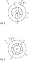
Figs. 1-4 thefunnel assembly 32 further comprises aniris blind assembly 36 arranged above alower edge 42 of thefunnel 34 and extending across theentire funnel 34. Theiris blind assembly 36 comprises anannular frame 50 andvarious iris segments 54 radially inwardly extending therefrom. Thevarious iris segments 54 are radially and/or tangentially displaceable between at least two extreme configurations as shown inFig. 3 and Fig. 4 . - The
various iris segments 54 are further operably connected and engaged with anactuation member 56 extending radially outwardly from theframe 50. By twisting or displacing theactuation member 56 from e.g. a 1 o'clock configuration as shown inFig. 3 towards an 11 o'clock configuration as shown inFig. 4 , thevarious iris segments 54 can be simultaneously displaced radially outwardly in order to increase the size of the throughopening 52 towards a maximum increased configuration as indicated inFig. 4 with 52'. Even though not particularly illustrated theactuation member 56 of theiris blind assembly 36 preferably protrudes from thefunnel 34 radially outwardly. - Only for reasons of simplicity, the
various iris segments 54 are not separately illustrated in the sketch ofFig. 2 . By means of theiris blind assembly 36 of variable size, the rate of evaporation of theliquid cooling agent 12 can be regulated and can be decreased. This way, contamination of the environment with evaporated orliquid cooling agent 12 can be reduced to a minimum, thereby enhancing operational safety and reducing the risk of burning or suffocating. - Furthermore and as illustrated in
Figs. 1 and2 , thefunnel 34 also comprises radially outwardly extending notches or recesses 38 extending from an inner wall of thefunnel 34. As shown inFig. 2 therecesses 38 comprise a slanted orinclined bottom portion 46 and arespective sidewall portion 44. By means of theinclined bottom portion 46, therecesses 38 are operable to support a liftedspecimen holder 18 in an inclined orientation above the blind assembly's 36 throughopening 52. Here, the pivotable orremovable support 49 is of particular use to keep a liftedspecimen holder 18 in the inclined orientation. - Additionally, it is conceivable to put the lifted
specimen holder 18 onto the closed irisblind assembly 36. The specimen holder may be lifted out of thestorage container 16 when the iris blind is in an opened configuration. Thereafter the size of the through opening 52 of theiris blind assembly 36 can be reduced to such an extend that the diameter of the remaining throughopening 52 is smaller than the cross section of thespecimen holder 18. Then thespecimen holder 18 can be positioned onto the segments of theiris blind assembly 36. In such a configuration the at least onesupport 49 orseveral supports 49 are operable to keep thespecimen holder 18 in a stable orientation, e.g. in an upright or inclined configuration. - When kept in an inclined orientation either on the
segments 54 of theiris blind assembly 36 or in the radially outwardly extendingrecess 38, excess cooling agent may drop or rinse down from various cryosample compartments 20 of thespecimen holder 18 as shown inFig. 2 in form of various drops 12'. Additionally but not illustrated here, the recovery assembly may be provided with an additional support, e.g. pivotally arranged by means of a hinge at an upper end orupper rim 48 of thefunnel 34. - Such a support may be folded to extend at least partially radially inwardly in order to support, to hold and to stabilize the
specimen holder 18 in an inclined orientation when leaned against the radially inwardly pivoted support. - Lifting of the specimen holder out of the
storage container 16 can be provided either manually, e.g. by gripping thehanger 24 orhook 26 with the hands of operating personal. Alternatively or additionally and as illustrated inFig. 1 an extraction assembly 60 can be provided, e.g. comprising apulley 62 that serves as a deflection wheel for achain 64 or for a comparable flexible strap. The chain may comprise ahook 68 to engage with acorresponding hook 26 provided at the upper end of thespecimen holder 18. - As further shown in
Fig. 1 , thepulley 62 is mounted on aceiling 66. By exertion of a lateral, sideward or even downward directed tensile load to the other free end of thechain 64, the specimen orspecimen holder 18 can be lifted and can be raised above a level of anupper edge 48 of thefunnel assembly 32. Alternatively, but not illustrated here, the pulley may be releasably mounted and fixed to the funnel assembly, e.g. by means of at least one, preferably two or three circumferentially distributed pillars extending upwardly from the funnel assembly in order to provide a support for thepulley 62. -
- 10
- cryopreservation device
- 12
- cooling agent
- 14
- Dewar wall structure
- 16
- storage container
- 18
- specimen holder
- 20
- compartment
- 24
- hanger
- 26
- hook
- 28
- rim
- 30
- neck portion
- 32
- funnel assembly
- 34
- funnel
- 36
- iris blind assembly
- 38
- recess
- 40
- support structure
- 41
- fastening
- 42
- edge
- 44
- sidewall portion
- 46
- bottom portion
- 48
- edge
- 49
- support
- 50
- frame
- 52
- through opening
- 54
- iris segment
- 56
- actuation member
- 60
- extraction assembly
- 62
- pulley
- 64
- chain
- 66
- ceiling
- 68
- hook
Claims (13)
- A recovery assembly for a cryopreservation device, comprising a cone-shaped funnel assembly (32) comprising a support (40) for mounting the funnel assembly (32) to an access opening of a cryopreservation container (16) to be at least partially filled with a cooling agent (12), characterized in that the funnel assembly (32) further comprises a blind assembly (36) extending across the inner cross-section of the funnel assembly (32).
- The recovery assembly according to claim 1, wherein the support (40) is adapted to receive an upper neck portion (30) and/or an upper rim (28) of the container (16).
- The recovery assembly according to claim 1 or 2, wherein the blind assembly (36) provides a through opening (52) of variable size.
- The recovery assembly according to any one of the preceding claims, wherein the blind assembly (36) comprises an iris blind.
- The recovery assembly according to claim any one of the preceding claims, wherein an actuation member (56) of the blind assembly (36) extends outside or from an outer circumference of the funnel assembly (32).
- The recovery assembly according to any one of the preceding claims, wherein the funnel assembly (32) comprises at least one outwardly extending recess (38) on an inside wall portion to support a specimen holder (18) in an inclined orientation above the access opening of the container (16).
- The recovery assembly according to claim 6, wherein the at least one recess (38) is located above the blind assembly (36).
- The recovery assembly according to claim 6 or 7, further comprising an additional support (49) extending from an upper end of the funnel assembly (32) obliquely opposite to the outwardly extending recess (38).
- The recovery assembly according to any one of the preceding claims, wherein the funnel assembly (32) comprises a thermally insulated material and/or a thermally insulated structure.
- The recovery assembly according to any one of the preceding claims, wherein the recovery assembly is releasably attachable to the container (16).
- The recover assembly according to any one of the preceding claims, wherein the blind assembly (36) comprises an annular frame (50) and multiple radially displaceable segments (54) extending in the plane of the frame (50).
- A cryopreservation device for storing of at least one specimen, the device comprising:- a cryopreservation container (16) to accommodate a liquid cooling agent (12) wherein said cryopreservation container comprises an access opening at a distal upper end, and- a recovery assembly according to any one of the preceding claims, wherein the recovery assembly is mounted on the access opening via its support (40).
- The cryopreservation device according to claim 12, wherein the recovery assembly is removably mounted on the access opening of the cryopreservation container (16).
Priority Applications (1)
| Application Number | Priority Date | Filing Date | Title |
|---|---|---|---|
| EP14747652.7A EP3030075B1 (en) | 2013-08-08 | 2014-08-05 | Recovery assembly for cryopreservation applications |
Applications Claiming Priority (3)
| Application Number | Priority Date | Filing Date | Title |
|---|---|---|---|
| EP13179685 | 2013-08-08 | ||
| EP14747652.7A EP3030075B1 (en) | 2013-08-08 | 2014-08-05 | Recovery assembly for cryopreservation applications |
| PCT/EP2014/066792 WO2015018817A1 (en) | 2013-08-08 | 2014-08-05 | Recovery assembly for cryopreservation applications |
Publications (2)
| Publication Number | Publication Date |
|---|---|
| EP3030075A1 EP3030075A1 (en) | 2016-06-15 |
| EP3030075B1 true EP3030075B1 (en) | 2018-06-13 |
Family
ID=48918301
Family Applications (1)
| Application Number | Title | Priority Date | Filing Date |
|---|---|---|---|
| EP14747652.7A Not-in-force EP3030075B1 (en) | 2013-08-08 | 2014-08-05 | Recovery assembly for cryopreservation applications |
Country Status (6)
| Country | Link |
|---|---|
| US (1) | US10258031B2 (en) |
| EP (1) | EP3030075B1 (en) |
| JP (1) | JP6463754B2 (en) |
| CN (1) | CN105407717B (en) |
| DK (1) | DK3030075T3 (en) |
| WO (1) | WO2015018817A1 (en) |
Families Citing this family (2)
| Publication number | Priority date | Publication date | Assignee | Title |
|---|---|---|---|---|
| JP6829865B2 (en) * | 2016-10-06 | 2021-02-17 | 株式会社北里コーポレーション | Canister set for container for cryopreservation of living cells |
| US11352262B2 (en) | 2017-12-18 | 2022-06-07 | Praxair Technology, Inc. | Methods for automatic filling, charging and dispensing carbon dioxide snow block |
Family Cites Families (14)
| Publication number | Priority date | Publication date | Assignee | Title |
|---|---|---|---|---|
| US4108338A (en) * | 1977-08-15 | 1978-08-22 | Pennwalt Corporation | Rotary tabletting press with powder feed adjustment valve |
| DE2750800C3 (en) * | 1977-11-14 | 1981-05-07 | Bosch-Siemens Hausgeräte GmbH, 7000 Stuttgart | Electric coffee maker |
| DE2928676B1 (en) | 1979-07-16 | 1980-06-04 | Herko Pyrolyse Recycling | Process for the condensation of carbonization gases from waste pyrolysis |
| FR2466405A1 (en) * | 1979-09-28 | 1981-04-10 | Air Liquide | DEVICE FOR STORING PRODUCTS SUCH AS SEEDS OR THE LIKE COMPRISING A CRYOBIOLOGICAL RESERVOIR |
| EP1356229A4 (en) | 2000-12-29 | 2009-11-18 | Cryoport Systems Llc | CRYOGENIC EXPEDITION CONTAINER |
| US7021198B1 (en) * | 2002-10-15 | 2006-04-04 | Wilbur Curtis Company, Inc. | Brew basket for coffee filter pack |
| DE10332799B4 (en) * | 2003-07-18 | 2007-03-01 | Fraunhofer-Gesellschaft zur Förderung der angewandten Forschung e.V. | Apparatus and method for handling a sample |
| JP4392260B2 (en) * | 2004-02-12 | 2009-12-24 | 中央開発株式会社 | Core sample storage device |
| JP5254218B2 (en) * | 2006-05-22 | 2013-08-07 | マイクロスコピー イノベーションズ エルエルシー | Apparatus and method for preparing and storing microscopic specimens for analysis |
| US8709797B2 (en) * | 2006-06-20 | 2014-04-29 | Cook General Biotechnology Llc | Systems and methods for cryopreservation of cells |
| DE102008057981B4 (en) | 2008-11-19 | 2010-09-02 | Fraunhofer-Gesellschaft zur Förderung der angewandten Forschung e.V. | cryostorage |
| JP2010172868A (en) * | 2009-02-02 | 2010-08-12 | Shibaura Mechatronics Corp | Apparatus and method for dropping liquid material |
| JP5318621B2 (en) * | 2009-03-23 | 2013-10-16 | 株式会社堀場製作所 | Low temperature liquefied gas injection device |
| CN203985779U (en) * | 2014-07-10 | 2014-12-10 | 深圳华大基因科技有限公司 | Cellular tissure vitrified frozen vector external member |
-
2014
- 2014-08-05 WO PCT/EP2014/066792 patent/WO2015018817A1/en not_active Ceased
- 2014-08-05 DK DK14747652.7T patent/DK3030075T3/en active
- 2014-08-05 JP JP2016532662A patent/JP6463754B2/en not_active Expired - Fee Related
- 2014-08-05 US US14/908,182 patent/US10258031B2/en not_active Expired - Fee Related
- 2014-08-05 EP EP14747652.7A patent/EP3030075B1/en not_active Not-in-force
- 2014-08-05 CN CN201480041930.XA patent/CN105407717B/en not_active Expired - Fee Related
Also Published As
| Publication number | Publication date |
|---|---|
| US20160165881A1 (en) | 2016-06-16 |
| CN105407717A (en) | 2016-03-16 |
| EP3030075A1 (en) | 2016-06-15 |
| DK3030075T3 (en) | 2018-09-24 |
| JP2016536554A (en) | 2016-11-24 |
| US10258031B2 (en) | 2019-04-16 |
| CN105407717B (en) | 2018-04-03 |
| WO2015018817A1 (en) | 2015-02-12 |
| HK1221605A1 (en) | 2017-06-09 |
| JP6463754B2 (en) | 2019-02-06 |
Similar Documents
| Publication | Publication Date | Title |
|---|---|---|
| US11540510B2 (en) | Method of storing and retrieving products using cryogenic storage rack with rotatable shelves | |
| JP6653283B2 (en) | Biological sample transport container | |
| US9488556B2 (en) | Cryogenic storage system for thermolabile specimens | |
| JP5026142B2 (en) | Cryopreservation container | |
| ES2760628T3 (en) | 30 or 90 ml disposable container for storing and transporting samples of human tissue or organs to be subjected to histological examination | |
| US20090255938A1 (en) | Cryogenic storage container | |
| US20100196873A1 (en) | Systems and Methods for Cryopreservation of Cells | |
| US10258031B2 (en) | Recovery assembly for cryopreservation applications | |
| US20160158759A1 (en) | Recovery assembly for cryopreservation applications | |
| CN102160546A (en) | Systems and methods for cryopreservation of cells | |
| JP2018088992A (en) | Cryopreservation container | |
| JP2008518034A (en) | Apparatus and method for preserving the cornea in vitro | |
| HK1221605B (en) | Recovery assembly for cryopreservation applications | |
| US20170341838A1 (en) | Removable Can Holding Refrigerator Container | |
| US6378314B1 (en) | Cryogenic system having unique storage frames for storing bio-organic specimens | |
| CN214047295U (en) | Cooling device used in stem cell cryopreservation | |
| KR102343792B1 (en) | Device for Embryo Cryopreservation | |
| JP7190936B2 (en) | Freeze transport container and storage container for freeze transport container that can be accommodated in the freeze transport container | |
| JP7386374B2 (en) | Canister cap for cryopreservation applications | |
| CN213639437U (en) | Cold preservation equipment of mctl cell | |
| KR101059520B1 (en) | Long term storage box for animals | |
| CN209581541U (en) | A kind of Pathologic specimen transport box | |
| KR20160004815A (en) | Necklace Box | |
| CN216071021U (en) | A kind of auxiliary device for bone marrow chromosome culture medium | |
| JP7698303B2 (en) | cryopreservation container |
Legal Events
| Date | Code | Title | Description |
|---|---|---|---|
| PUAI | Public reference made under article 153(3) epc to a published international application that has entered the european phase |
Free format text: ORIGINAL CODE: 0009012 |
|
| 17P | Request for examination filed |
Effective date: 20160201 |
|
| AK | Designated contracting states |
Kind code of ref document: A1 Designated state(s): AL AT BE BG CH CY CZ DE DK EE ES FI FR GB GR HR HU IE IS IT LI LT LU LV MC MK MT NL NO PL PT RO RS SE SI SK SM TR |
|
| AX | Request for extension of the european patent |
Extension state: BA ME |
|
| DAX | Request for extension of the european patent (deleted) | ||
| REG | Reference to a national code |
Ref country code: HK Ref legal event code: DE Ref document number: 1221605 Country of ref document: HK |
|
| GRAP | Despatch of communication of intention to grant a patent |
Free format text: ORIGINAL CODE: EPIDOSNIGR1 |
|
| INTG | Intention to grant announced |
Effective date: 20171130 |
|
| GRAS | Grant fee paid |
Free format text: ORIGINAL CODE: EPIDOSNIGR3 |
|
| GRAJ | Information related to disapproval of communication of intention to grant by the applicant or resumption of examination proceedings by the epo deleted |
Free format text: ORIGINAL CODE: EPIDOSDIGR1 |
|
| GRAL | Information related to payment of fee for publishing/printing deleted |
Free format text: ORIGINAL CODE: EPIDOSDIGR3 |
|
| GRAP | Despatch of communication of intention to grant a patent |
Free format text: ORIGINAL CODE: EPIDOSNIGR1 |
|
| INTC | Intention to grant announced (deleted) | ||
| GRAA | (expected) grant |
Free format text: ORIGINAL CODE: 0009210 |
|
| INTG | Intention to grant announced |
Effective date: 20180426 |
|
| AK | Designated contracting states |
Kind code of ref document: B1 Designated state(s): AL AT BE BG CH CY CZ DE DK EE ES FI FR GB GR HR HU IE IS IT LI LT LU LV MC MK MT NL NO PL PT RO RS SE SI SK SM TR |
|
| REG | Reference to a national code |
Ref country code: GB Ref legal event code: FG4D |
|
| REG | Reference to a national code |
Ref country code: CH Ref legal event code: EP Ref country code: AT Ref legal event code: REF Ref document number: 1007489 Country of ref document: AT Kind code of ref document: T Effective date: 20180615 |
|
| REG | Reference to a national code |
Ref country code: IE Ref legal event code: FG4D |
|
| REG | Reference to a national code |
Ref country code: DE Ref legal event code: R096 Ref document number: 602014026996 Country of ref document: DE Ref country code: FR Ref legal event code: PLFP Year of fee payment: 5 |
|
| REG | Reference to a national code |
Ref country code: DK Ref legal event code: T3 Effective date: 20180919 |
|
| REG | Reference to a national code |
Ref country code: NL Ref legal event code: MP Effective date: 20180613 |
|
| REG | Reference to a national code |
Ref country code: LT Ref legal event code: MG4D |
|
| PG25 | Lapsed in a contracting state [announced via postgrant information from national office to epo] |
Ref country code: ES Free format text: LAPSE BECAUSE OF FAILURE TO SUBMIT A TRANSLATION OF THE DESCRIPTION OR TO PAY THE FEE WITHIN THE PRESCRIBED TIME-LIMIT Effective date: 20180613 Ref country code: NO Free format text: LAPSE BECAUSE OF FAILURE TO SUBMIT A TRANSLATION OF THE DESCRIPTION OR TO PAY THE FEE WITHIN THE PRESCRIBED TIME-LIMIT Effective date: 20180913 Ref country code: SE Free format text: LAPSE BECAUSE OF FAILURE TO SUBMIT A TRANSLATION OF THE DESCRIPTION OR TO PAY THE FEE WITHIN THE PRESCRIBED TIME-LIMIT Effective date: 20180613 Ref country code: FI Free format text: LAPSE BECAUSE OF FAILURE TO SUBMIT A TRANSLATION OF THE DESCRIPTION OR TO PAY THE FEE WITHIN THE PRESCRIBED TIME-LIMIT Effective date: 20180613 Ref country code: BG Free format text: LAPSE BECAUSE OF FAILURE TO SUBMIT A TRANSLATION OF THE DESCRIPTION OR TO PAY THE FEE WITHIN THE PRESCRIBED TIME-LIMIT Effective date: 20180913 Ref country code: CY Free format text: LAPSE BECAUSE OF FAILURE TO SUBMIT A TRANSLATION OF THE DESCRIPTION OR TO PAY THE FEE WITHIN THE PRESCRIBED TIME-LIMIT Effective date: 20180613 Ref country code: LT Free format text: LAPSE BECAUSE OF FAILURE TO SUBMIT A TRANSLATION OF THE DESCRIPTION OR TO PAY THE FEE WITHIN THE PRESCRIBED TIME-LIMIT Effective date: 20180613 |
|
| PG25 | Lapsed in a contracting state [announced via postgrant information from national office to epo] |
Ref country code: LV Free format text: LAPSE BECAUSE OF FAILURE TO SUBMIT A TRANSLATION OF THE DESCRIPTION OR TO PAY THE FEE WITHIN THE PRESCRIBED TIME-LIMIT Effective date: 20180613 Ref country code: RS Free format text: LAPSE BECAUSE OF FAILURE TO SUBMIT A TRANSLATION OF THE DESCRIPTION OR TO PAY THE FEE WITHIN THE PRESCRIBED TIME-LIMIT Effective date: 20180613 Ref country code: HR Free format text: LAPSE BECAUSE OF FAILURE TO SUBMIT A TRANSLATION OF THE DESCRIPTION OR TO PAY THE FEE WITHIN THE PRESCRIBED TIME-LIMIT Effective date: 20180613 Ref country code: GR Free format text: LAPSE BECAUSE OF FAILURE TO SUBMIT A TRANSLATION OF THE DESCRIPTION OR TO PAY THE FEE WITHIN THE PRESCRIBED TIME-LIMIT Effective date: 20180914 |
|
| REG | Reference to a national code |
Ref country code: AT Ref legal event code: MK05 Ref document number: 1007489 Country of ref document: AT Kind code of ref document: T Effective date: 20180613 |
|
| PG25 | Lapsed in a contracting state [announced via postgrant information from national office to epo] |
Ref country code: NL Free format text: LAPSE BECAUSE OF FAILURE TO SUBMIT A TRANSLATION OF THE DESCRIPTION OR TO PAY THE FEE WITHIN THE PRESCRIBED TIME-LIMIT Effective date: 20180613 |
|
| REG | Reference to a national code |
Ref country code: HK Ref legal event code: GR Ref document number: 1221605 Country of ref document: HK |
|
| PG25 | Lapsed in a contracting state [announced via postgrant information from national office to epo] |
Ref country code: CZ Free format text: LAPSE BECAUSE OF FAILURE TO SUBMIT A TRANSLATION OF THE DESCRIPTION OR TO PAY THE FEE WITHIN THE PRESCRIBED TIME-LIMIT Effective date: 20180613 Ref country code: RO Free format text: LAPSE BECAUSE OF FAILURE TO SUBMIT A TRANSLATION OF THE DESCRIPTION OR TO PAY THE FEE WITHIN THE PRESCRIBED TIME-LIMIT Effective date: 20180613 Ref country code: IS Free format text: LAPSE BECAUSE OF FAILURE TO SUBMIT A TRANSLATION OF THE DESCRIPTION OR TO PAY THE FEE WITHIN THE PRESCRIBED TIME-LIMIT Effective date: 20181013 Ref country code: AT Free format text: LAPSE BECAUSE OF FAILURE TO SUBMIT A TRANSLATION OF THE DESCRIPTION OR TO PAY THE FEE WITHIN THE PRESCRIBED TIME-LIMIT Effective date: 20180613 Ref country code: EE Free format text: LAPSE BECAUSE OF FAILURE TO SUBMIT A TRANSLATION OF THE DESCRIPTION OR TO PAY THE FEE WITHIN THE PRESCRIBED TIME-LIMIT Effective date: 20180613 Ref country code: SK Free format text: LAPSE BECAUSE OF FAILURE TO SUBMIT A TRANSLATION OF THE DESCRIPTION OR TO PAY THE FEE WITHIN THE PRESCRIBED TIME-LIMIT Effective date: 20180613 Ref country code: PL Free format text: LAPSE BECAUSE OF FAILURE TO SUBMIT A TRANSLATION OF THE DESCRIPTION OR TO PAY THE FEE WITHIN THE PRESCRIBED TIME-LIMIT Effective date: 20180613 |
|
| PG25 | Lapsed in a contracting state [announced via postgrant information from national office to epo] |
Ref country code: IT Free format text: LAPSE BECAUSE OF FAILURE TO SUBMIT A TRANSLATION OF THE DESCRIPTION OR TO PAY THE FEE WITHIN THE PRESCRIBED TIME-LIMIT Effective date: 20180613 Ref country code: SM Free format text: LAPSE BECAUSE OF FAILURE TO SUBMIT A TRANSLATION OF THE DESCRIPTION OR TO PAY THE FEE WITHIN THE PRESCRIBED TIME-LIMIT Effective date: 20180613 |
|
| REG | Reference to a national code |
Ref country code: DE Ref legal event code: R097 Ref document number: 602014026996 Country of ref document: DE |
|
| PG25 | Lapsed in a contracting state [announced via postgrant information from national office to epo] |
Ref country code: MC Free format text: LAPSE BECAUSE OF FAILURE TO SUBMIT A TRANSLATION OF THE DESCRIPTION OR TO PAY THE FEE WITHIN THE PRESCRIBED TIME-LIMIT Effective date: 20180613 |
|
| PLBE | No opposition filed within time limit |
Free format text: ORIGINAL CODE: 0009261 |
|
| STAA | Information on the status of an ep patent application or granted ep patent |
Free format text: STATUS: NO OPPOSITION FILED WITHIN TIME LIMIT |
|
| PG25 | Lapsed in a contracting state [announced via postgrant information from national office to epo] |
Ref country code: LU Free format text: LAPSE BECAUSE OF NON-PAYMENT OF DUE FEES Effective date: 20180805 |
|
| REG | Reference to a national code |
Ref country code: BE Ref legal event code: MM Effective date: 20180831 |
|
| 26N | No opposition filed |
Effective date: 20190314 |
|
| REG | Reference to a national code |
Ref country code: IE Ref legal event code: MM4A |
|
| PG25 | Lapsed in a contracting state [announced via postgrant information from national office to epo] |
Ref country code: SI Free format text: LAPSE BECAUSE OF FAILURE TO SUBMIT A TRANSLATION OF THE DESCRIPTION OR TO PAY THE FEE WITHIN THE PRESCRIBED TIME-LIMIT Effective date: 20180613 |
|
| PG25 | Lapsed in a contracting state [announced via postgrant information from national office to epo] |
Ref country code: IE Free format text: LAPSE BECAUSE OF NON-PAYMENT OF DUE FEES Effective date: 20180805 |
|
| PG25 | Lapsed in a contracting state [announced via postgrant information from national office to epo] |
Ref country code: BE Free format text: LAPSE BECAUSE OF NON-PAYMENT OF DUE FEES Effective date: 20180831 |
|
| PGFP | Annual fee paid to national office [announced via postgrant information from national office to epo] |
Ref country code: FR Payment date: 20190711 Year of fee payment: 6 Ref country code: DE Payment date: 20190723 Year of fee payment: 6 Ref country code: DK Payment date: 20190813 Year of fee payment: 6 Ref country code: TR Payment date: 20190725 Year of fee payment: 6 |
|
| PG25 | Lapsed in a contracting state [announced via postgrant information from national office to epo] |
Ref country code: AL Free format text: LAPSE BECAUSE OF FAILURE TO SUBMIT A TRANSLATION OF THE DESCRIPTION OR TO PAY THE FEE WITHIN THE PRESCRIBED TIME-LIMIT Effective date: 20180613 |
|
| PGFP | Annual fee paid to national office [announced via postgrant information from national office to epo] |
Ref country code: GB Payment date: 20190731 Year of fee payment: 6 |
|
| PG25 | Lapsed in a contracting state [announced via postgrant information from national office to epo] |
Ref country code: MT Free format text: LAPSE BECAUSE OF NON-PAYMENT OF DUE FEES Effective date: 20180805 |
|
| PGFP | Annual fee paid to national office [announced via postgrant information from national office to epo] |
Ref country code: CH Payment date: 20190819 Year of fee payment: 6 |
|
| PG25 | Lapsed in a contracting state [announced via postgrant information from national office to epo] |
Ref country code: PT Free format text: LAPSE BECAUSE OF FAILURE TO SUBMIT A TRANSLATION OF THE DESCRIPTION OR TO PAY THE FEE WITHIN THE PRESCRIBED TIME-LIMIT Effective date: 20180613 |
|
| PG25 | Lapsed in a contracting state [announced via postgrant information from national office to epo] |
Ref country code: MK Free format text: LAPSE BECAUSE OF NON-PAYMENT OF DUE FEES Effective date: 20180613 Ref country code: HU Free format text: LAPSE BECAUSE OF FAILURE TO SUBMIT A TRANSLATION OF THE DESCRIPTION OR TO PAY THE FEE WITHIN THE PRESCRIBED TIME-LIMIT; INVALID AB INITIO Effective date: 20140805 |
|
| REG | Reference to a national code |
Ref country code: DE Ref legal event code: R119 Ref document number: 602014026996 Country of ref document: DE |
|
| REG | Reference to a national code |
Ref country code: DK Ref legal event code: EBP Effective date: 20200831 |
|
| REG | Reference to a national code |
Ref country code: CH Ref legal event code: PL |
|
| GBPC | Gb: european patent ceased through non-payment of renewal fee |
Effective date: 20200805 |
|
| PG25 | Lapsed in a contracting state [announced via postgrant information from national office to epo] |
Ref country code: LI Free format text: LAPSE BECAUSE OF NON-PAYMENT OF DUE FEES Effective date: 20200831 Ref country code: CH Free format text: LAPSE BECAUSE OF NON-PAYMENT OF DUE FEES Effective date: 20200831 |
|
| PG25 | Lapsed in a contracting state [announced via postgrant information from national office to epo] |
Ref country code: DE Free format text: LAPSE BECAUSE OF NON-PAYMENT OF DUE FEES Effective date: 20210302 Ref country code: FR Free format text: LAPSE BECAUSE OF NON-PAYMENT OF DUE FEES Effective date: 20200831 |
|
| PG25 | Lapsed in a contracting state [announced via postgrant information from national office to epo] |
Ref country code: GB Free format text: LAPSE BECAUSE OF NON-PAYMENT OF DUE FEES Effective date: 20200805 Ref country code: DK Free format text: LAPSE BECAUSE OF NON-PAYMENT OF DUE FEES Effective date: 20200831 |
|
| PG25 | Lapsed in a contracting state [announced via postgrant information from national office to epo] |
Ref country code: TR Free format text: LAPSE BECAUSE OF NON-PAYMENT OF DUE FEES Effective date: 20200805 |