EP3030045B1 - Over-the-range microwave oven and method of using the same - Google Patents
Over-the-range microwave oven and method of using the same Download PDFInfo
- Publication number
- EP3030045B1 EP3030045B1 EP15169720.8A EP15169720A EP3030045B1 EP 3030045 B1 EP3030045 B1 EP 3030045B1 EP 15169720 A EP15169720 A EP 15169720A EP 3030045 B1 EP3030045 B1 EP 3030045B1
- Authority
- EP
- European Patent Office
- Prior art keywords
- disposed
- pair
- housing
- microwave oven
- over
- Prior art date
- Legal status (The legal status is an assumption and is not a legal conclusion. Google has not performed a legal analysis and makes no representation as to the accuracy of the status listed.)
- Not-in-force
Links
- 238000000034 method Methods 0.000 title description 2
- 238000010411 cooking Methods 0.000 claims description 19
- 230000003247 decreasing effect Effects 0.000 claims description 9
- 238000005192 partition Methods 0.000 description 5
- 239000000463 material Substances 0.000 description 2
- 239000007769 metal material Substances 0.000 description 2
- 239000003610 charcoal Substances 0.000 description 1
- 239000000356 contaminant Substances 0.000 description 1
- 238000007599 discharging Methods 0.000 description 1
- 230000000694 effects Effects 0.000 description 1
- 238000001914 filtration Methods 0.000 description 1
- 238000000638 solvent extraction Methods 0.000 description 1
- 239000005341 toughened glass Substances 0.000 description 1
Images

Classifications
-
- H—ELECTRICITY
- H05—ELECTRIC TECHNIQUES NOT OTHERWISE PROVIDED FOR
- H05B—ELECTRIC HEATING; ELECTRIC LIGHT SOURCES NOT OTHERWISE PROVIDED FOR; CIRCUIT ARRANGEMENTS FOR ELECTRIC LIGHT SOURCES, IN GENERAL
- H05B6/00—Heating by electric, magnetic or electromagnetic fields
- H05B6/64—Heating using microwaves
- H05B6/642—Cooling of the microwave components and related air circulation systems
- H05B6/6423—Cooling of the microwave components and related air circulation systems wherein the microwave oven air circulation system is also used as air extracting hood
-
- F—MECHANICAL ENGINEERING; LIGHTING; HEATING; WEAPONS; BLASTING
- F24—HEATING; RANGES; VENTILATING
- F24C—DOMESTIC STOVES OR RANGES ; DETAILS OF DOMESTIC STOVES OR RANGES, OF GENERAL APPLICATION
- F24C7/00—Stoves or ranges heated by electric energy
- F24C7/02—Stoves or ranges heated by electric energy using microwaves
-
- F—MECHANICAL ENGINEERING; LIGHTING; HEATING; WEAPONS; BLASTING
- F24—HEATING; RANGES; VENTILATING
- F24C—DOMESTIC STOVES OR RANGES ; DETAILS OF DOMESTIC STOVES OR RANGES, OF GENERAL APPLICATION
- F24C15/00—Details
- F24C15/006—Arrangements for circulation of cooling air
-
- F—MECHANICAL ENGINEERING; LIGHTING; HEATING; WEAPONS; BLASTING
- F24—HEATING; RANGES; VENTILATING
- F24C—DOMESTIC STOVES OR RANGES ; DETAILS OF DOMESTIC STOVES OR RANGES, OF GENERAL APPLICATION
- F24C15/00—Details
- F24C15/20—Removing cooking fumes
-
- F—MECHANICAL ENGINEERING; LIGHTING; HEATING; WEAPONS; BLASTING
- F24—HEATING; RANGES; VENTILATING
- F24C—DOMESTIC STOVES OR RANGES ; DETAILS OF DOMESTIC STOVES OR RANGES, OF GENERAL APPLICATION
- F24C15/00—Details
- F24C15/20—Removing cooking fumes
- F24C15/2035—Arrangement or mounting of filters
-
- F—MECHANICAL ENGINEERING; LIGHTING; HEATING; WEAPONS; BLASTING
- F24—HEATING; RANGES; VENTILATING
- F24C—DOMESTIC STOVES OR RANGES ; DETAILS OF DOMESTIC STOVES OR RANGES, OF GENERAL APPLICATION
- F24C15/00—Details
- F24C15/20—Removing cooking fumes
- F24C15/2042—Devices for removing cooking fumes structurally associated with a cooking range e.g. downdraft
-
- F—MECHANICAL ENGINEERING; LIGHTING; HEATING; WEAPONS; BLASTING
- F24—HEATING; RANGES; VENTILATING
- F24C—DOMESTIC STOVES OR RANGES ; DETAILS OF DOMESTIC STOVES OR RANGES, OF GENERAL APPLICATION
- F24C7/00—Stoves or ranges heated by electric energy
- F24C7/08—Arrangement or mounting of control or safety devices
- F24C7/082—Arrangement or mounting of control or safety devices on ranges, e.g. control panels, illumination
- F24C7/086—Arrangement or mounting of control or safety devices on ranges, e.g. control panels, illumination touch control
-
- Y—GENERAL TAGGING OF NEW TECHNOLOGICAL DEVELOPMENTS; GENERAL TAGGING OF CROSS-SECTIONAL TECHNOLOGIES SPANNING OVER SEVERAL SECTIONS OF THE IPC; TECHNICAL SUBJECTS COVERED BY FORMER USPC CROSS-REFERENCE ART COLLECTIONS [XRACs] AND DIGESTS
- Y02—TECHNOLOGIES OR APPLICATIONS FOR MITIGATION OR ADAPTATION AGAINST CLIMATE CHANGE
- Y02B—CLIMATE CHANGE MITIGATION TECHNOLOGIES RELATED TO BUILDINGS, e.g. HOUSING, HOUSE APPLIANCES OR RELATED END-USER APPLICATIONS
- Y02B40/00—Technologies aiming at improving the efficiency of home appliances, e.g. induction cooking or efficient technologies for refrigerators, freezers or dish washers
Definitions
- the present disclosure relates to an over-the-range microwave oven in which a structure of an air discharge flow path of an air discharge duct is improved.
- an over-the-range microwave oven refers to a microwave oven that has a function of discharging air, and the over-the-range microwave oven is disposed to be spaced apart from an upper side of a gas range in order to implement the aforementioned function.
- an over-the-range microwave oven which may effectively convey air, may be excellent in terms of electric power consumption characteristics, and may have a flow path that reduces noise, even though performance of the air discharge unit is increased.
- the present disclosure has been made in an effort to provide a hood or an over-the-range microwave oven which is excellent in terms of electric power consumption characteristics, and has an improved structure that reduces noise, by preventing the occurrence of a turbulent flow in a duct even though output of an air discharge unit is increased.
- an over-the-range microwave oven including: a housing which defines an external appearance; a cooking unit which is disposed in the housing; a duct unit which is disposed in the housing; a first plate which is disposed between the housing and the cooking unit, forms a flow path, and forms a bottom surface of the duct unit; and at least a pair of second plates which is disposed at both lateral sides of the first plate and disposed so that an interval therebetween is decreased from one side end toward the other side end.
- the over-the-range microwave oven further includes an air discharge unit which is disposed at the rear of the housing and allows air to flow into the inlet hole, in which the air discharge unit includes an air discharge motor, and an impeller which is operated by the air discharge motor and allows air to flow into the inlet hole.
- the over-the-range microwave oven further includes a third plate which is disposed at the rear of the pair of second plates and has an inlet hole into which air flows.
- the third plate includes a first inlet hole, and a second inlet hole
- the impeller includes a first impeller which is disposed at one side of the air discharge motor so as to allow air to flow into the first inlet hole, and a second impeller which is disposed at the other side of the air discharge motor so as to allow air to flow into the second inlet hole.
- the third plate further includes a bent portion which protrudes forward between the first inlet hole and the second inlet hole.
- the bent portion may be formed to become narrower toward the front side.
- the bent portion may be formed in a trapezoidal shape.
- the pair of second plates may preferably include: a pair of first portions which is disposed at both sides of the third plate, respectively, and parallel with each other; a pair of inclined portions which is extended from the pair of first portions, respectively, and has an interval therebetween that is gradually decreased; and a pair of second portions which is extended from the pair of inclined portions, respectively, and parallel with each other.
- a connecting surface between the first portion and the inclined portion or a connecting surface between the inclined portion and the second portion may preferably be tapered or rounded.
- the pair of second plates may be formed symmetrically.
- a filter may preferably be disposed in front of the pair of second plates.
- the air discharge unit is disposed so as to allow air to flow from the rear side to the front side, a protruding portion of the third plate is provided, and a duct structure of the second plates, which is symmetrically formed to become narrower, is provided, such that the occurrence of a turbulent flow is prevented regardless of output of the air discharge unit, thereby providing the over-the-range microwave oven that is excellent in terms of electric power consumption characteristics, and reducing noise.
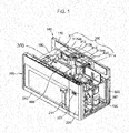
- FIG. 1 is a perspective view illustrating an over-the-range microwave oven according to an exemplary embodiment of the present disclosure in which an upper housing and a lateral side housing are removed
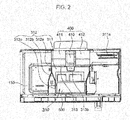
- FIG. 2 is a top view of FIG. 1
- FIG. 3 is a view illustrating an air flow in the over-the-range microwave oven according to the exemplary embodiment of the present disclosure.
- the exemplary embodiment may widely include a housing 100, a cooking unit 200, a duct unit 300, and an air discharge unit 400, and may further include a filter unit 500.
- the housing 100 defines an external appearance of the over-the-range microwave oven, and may be made of a metallic material or a nonmetallic material.
- the housing 100 may widely include an upper housing and a lateral side housing, which are not illustrated, and a rear housing 110 and a lower housing 120, which are illustrated.
- the respective housings 100 may be integrally formed or may be detachably coupled to each other.
- the housing 100 may further include a partition housing 130 which may vertically partition the interior of the housing 100 into the cooking unit 200 and the duct unit 300.
- the partition housing 130 may be formed integrally with the housing 100, or may be fastened to the housing 100 by bolting.
- the housing 100 may be formed as an outer wall of the duct unit 300 which will be described below.
- the cooking unit 200 is disposed in the housing 100, and may include a cooking chamber, and an electric equipment chamber.
- a door 210 may be disposed in the front of the cooking chamber.
- the door 210 may be hingedly coupled to the housing 100 so as to be closed and opened toward one side, and a handle 211 may be disposed on the door 210 so as to allow a user to easily open and close the door 210.
- the door 210 may further include a transparent window 212 made of tempered glass which is disposed at a center of the door 210.
- the cooking unit 200 may be provided with a control panel 220 at one side of the door 210.
- the control panel 220 may include buttons, a touch panel, or a dial so as to allow the user to control the cooking unit 200, and may include a display unit 221 so as to allow the user to confirm various types of information of the over-the-range microwave oven according to the exemplary embodiment with the naked eye.
- control panel 220 may include buttons, a touch panel, or a dial so as to allow the user to operate the duct unit 300 which will be described below.
- the duct unit 300 may be disposed in the housing 100. Specifically, the duct unit 300 is disposed between the housing 100 and the cooking unit 200 so as to form a flow path, and may be widely divided into an upper duct unit 310, and a lateral side duct unit 320.
- the lateral side duct unit 320 is formed between the cooking unit 200 and the lateral side housing (not illustrated) or between the control panel 220 and the lateral side housing (not illustrated).
- the housing 100 may be formed as an outer wall of the duct unit 300.
- the lateral side duct unit 320 includes a first inlet port 321 which is opened at the lower housing 120 and into which outside air flows, and guides air flowing from the first inlet port 321 to flow to the upper duct unit 310 which will be described below.
- a plurality of first inlet ports 321 may be formed.
- the upper duct unit 310 may be disposed at an upper side of the cooking unit 200, and may include a first plate 311, second plates 312, and/or a third plate 313.
- the exemplary embodiment may efficiently form an air discharge flow path from a rear side toward a front side, and may implement a hood and an over-the-range microwave oven which may reduce the occurrence of turbulent flows, electric power consumption, and noise even though a larger amount of driving power is used.
- the first plate 311 may be disposed between the housing 100 and the cooking unit 200, may form a flow path, and may form a bottom surface of the duct unit 310.
- the first plate 311 is disposed in the housing 100 so as to form a bottom surface of the upper duct unit, and may be disposed at an upper side of the cooking unit 200 by being disposed at an upper side of the partition housing 130.
- the first plate 311 may be integrally formed as an upper surface of the partition housing 130.
- the first plate 311 includes second inlet ports 311 a, at a rear side thereof, through which air flowing from the lateral side duct unit 320 flows into the upper duct unit 310.
- the second inlet ports 311 a may be formed at both sides at the rear side of the first plate 311, respectively, so as to correspond to a first impeller 411 and a second impeller 412 which will be described below.
- the first plate 311 may be made of a metallic material or a plastic material.
- At least a pair of second plates 312 may be disposed at both lateral sides of the first plate 311, and formed so that an interval therebetween is decreased from one side end toward the other side end.
- two second plates 312 are disposed as a pair between the first plate 311 and the housing 100 so as to form both lateral side surfaces of the upper duct unit, thereby partitioning the interior of the upper duct unit 310.
- the pair of second plates 312 may be formed so that an interval therebetween is decreased in a direction from a portion, into which air flows, toward a portion where air is discharged. Specifically, the pair of second plates 312 may be formed to be symmetrically disposed so that an interval therebetween is decreased toward the front side.
- the pair of second plates 312 may include a pair of first portions 312a which is disposed at both sides of the third plate 313 which will be described below, respectively, and parallel with each other, a pair of inclined portions 312b which is extended from the pair of first portions 312a, respectively, and has an interval therebetween that is gradually decreased, and a pair of second portions 312c which is extended from the pair of inclined portions 312b, respectively, and parallel with each other.
- the flow path which is formed symmetrically and becomes narrower toward the front side, may greatly improve flow efficiency of the air discharge flow path compared to the related art, and may reduce the occurrence of noise.
- a connecting surface between the first portion 312a and the inclined portion 312b or a connecting surface between the inclined portion 312b and the second portion 312c may be tapered or rounded, thereby more efficiently forming an air discharge flow path.
- the third plate 313 is disposed at the rear of the pair of second plates 312, and may have inlet holes 313aa and 313ab into which air flows.
- air may pass through the first inlet port 321 formed at the lower side or at the lateral side, and the second inlet ports 311a formed in the first plate 311, may pass through the impellers 411 and 412 which will be described below, may flow into the inlet holes 313aa and 313ab, and then may be discharged to the outside through a flow path formed by the first plate 311, the second plates 312, and the upper housing 100.
- the third plate 313 may include the first inlet hole 313aa which corresponds to the first impeller 411 which will be described below, and the second inlet hole 313ab which corresponds to the second impeller 412 which will be described below, thereby more effectively implementing an air flow.
- the third plate 313 may further include a bent portion 313b, which is formed between the first inlet hole 313aa and the second inlet hole 313ab so as to protrude forward, thereby more efficiently implementing an air flow.
- the bent portion 313b may be formed in various shapes that become narrower toward the front side.
- the bent portion 313b may be formed in a trapezoidal shape.
- the air discharge unit 400 is disposed between the third plate 313 and a rear surface of the housing 100, and allows air to flow into the inlet holes 313aa and 313ab.
- the air discharge unit 400 may include an air discharge motor 410, and the impellers 411 and 412 which are operated by the air discharge motor 410 and allow air to flow into the inlet holes 313aa and 313ab.
- the impellers 411 and 412 include the first impeller 411 which is disposed at one side of the air discharge motor 410, and the second impeller 412 which is disposed at the other side of the air discharge motor 410. Both ends of the first impeller 411 and the second impeller 412 are disposed to correspond to the aforementioned second inlet ports 311 a, respectively, thereby allowing air sucked from the outside to flow into a space formed by the housing 100, the first plate 311, and the second plates 312.
- the filter unit 500 may be disposed at the front side of the pair of second plates 312, and specifically, may be disposed on the second portion 312c.
- the filter unit 500 may be implemented as a charcoal filter, may filter air that is finally discharged to the outside, and may be disposed detachably.
- the air discharge unit 400 is operated using the buttons, the touch panel, or the dial disposed on the control panel 220.
- the air discharge motor 410 is operated by being supplied with external electric power such that both of the impellers 411 and 412 are axially rotated, and outside air flows from the first inlet port 321 of the lateral side housing into the over-the-range microwave oven according to the exemplary embodiment, and then flows into the impellers 411 and 412 through the second inlet ports 311a formed in the first plate 311.
- air flowing into the impellers 411 and 412 is discharged at a high speed, and then flows into a duct, which is formed by the housing 100, the first plate 311, and the second plates 312, through the inlet holes 313aa and 313ab of the third plate 313.
- the bent portion 313b formed on the third plate 313 guides the air flow toward the front side while preventing the occurrence of a turbulent flow of air flowing from the respective impellers 411 and 412.
- the shape of the second plates 312, which is symmetrically formed to become narrower, may allow air to be quickly discharged to the outside.
- the filter is disposed between the second horizontal portions 312c that form the narrowest flow path, thereby effectively filtering contaminants.
- the operated air discharge unit 400 air around a gas range or air flowing by a drive unit of a microwave oven may be discharged through the upper duct unit 310, which is disposed between the housing 100 and the cooking unit 200 and forms a flow path, and which includes the first plate 311 which is disposed at the upper side of the cooking unit 200, the pair of second plates 312 which is disposed between the first plate 311 and the housing 100 and disposed symmetrically so that an interval therebetween is decreased toward the front side, and the third plate 313 which is disposed at the rear of the pair of second plates 312 and has the inlet holes 313aa and 313ab into which air flows.
- the exemplary embodiment of the present disclosure disposes the air discharge unit 400 at the rear side so as to guide air from the rear side toward the front side, and provides the flow path which is symmetrically formed to become narrower toward the discharge port in order to further increase the aforementioned effect.
Landscapes
- Engineering & Computer Science (AREA)
- Chemical & Material Sciences (AREA)
- Combustion & Propulsion (AREA)
- Mechanical Engineering (AREA)
- General Engineering & Computer Science (AREA)
- Physics & Mathematics (AREA)
- Electromagnetism (AREA)
- Electric Ovens (AREA)
Description
- The present disclosure relates to an over-the-range microwave oven in which a structure of an air discharge flow path of an air discharge duct is improved.
- In general, an over-the-range microwave oven refers to a microwave oven that has a function of discharging air, and the over-the-range microwave oven is disposed to be spaced apart from an upper side of a gas range in order to implement the aforementioned function.
- Recently, in the over-the-range microwave oven, an air discharge unit is provided in an air discharge duct so that a conveying flow rate of air is typically about 680 m3/h (= 400 CFM).
- However, when performance of the air discharge unit is increased in order to improve efficiency of air discharge performance, there is a problem in that a turbulent flow occurs in the air discharge unit, noise is increased, or electric power is excessively consumed, and as a result, efficiency of the over-the-range microwave oven deteriorates.
- The prior art documents
KR 2013 0036415 A US 4 886 046 A andUS 2008/156793 A1 disclose over-the-range microwave ovens showing the features of the preamble of claim 1. They obviously suffer from the problems discussed above. - Therefore, it is urgently needed to develop an over-the-range microwave oven which may effectively convey air, may be excellent in terms of electric power consumption characteristics, and may have a flow path that reduces noise, even though performance of the air discharge unit is increased.
- The present disclosure has been made in an effort to provide a hood or an over-the-range microwave oven which is excellent in terms of electric power consumption characteristics, and has an improved structure that reduces noise, by preventing the occurrence of a turbulent flow in a duct even though output of an air discharge unit is increased.
- This object is achieved by an over-the-range microwave oven according to claim 1 including: a housing which defines an external appearance; a cooking unit which is disposed in the housing; a duct unit which is disposed in the housing; a first plate which is disposed between the housing and the cooking unit, forms a flow path, and forms a bottom surface of the duct unit; and at least a pair of second plates which is disposed at both lateral sides of the first plate and disposed so that an interval therebetween is decreased from one side end toward the other side end.
- In addition, the over-the-range microwave oven further includes an air discharge unit which is disposed at the rear of the housing and allows air to flow into the inlet hole, in which the air discharge unit includes an air discharge motor, and an impeller which is operated by the air discharge motor and allows air to flow into the inlet hole.
- In addition, the over-the-range microwave oven further includes a third plate which is disposed at the rear of the pair of second plates and has an inlet hole into which air flows.
- In addition, the third plate includes a first inlet hole, and a second inlet hole, and the impeller includes a first impeller which is disposed at one side of the air discharge motor so as to allow air to flow into the first inlet hole, and a second impeller which is disposed at the other side of the air discharge motor so as to allow air to flow into the second inlet hole.
- In addition, the third plate further includes a bent portion which protrudes forward between the first inlet hole and the second inlet hole.
- According to a preferred embodiment of the invention the bent portion may be formed to become narrower toward the front side.
- According 2 a further preferred embodiment of the invention the bent portion may be formed in a trapezoidal shape.
- In addition, the pair of second plates may preferably include: a pair of first portions which is disposed at both sides of the third plate, respectively, and parallel with each other; a pair of inclined portions which is extended from the pair of first portions, respectively, and has an interval therebetween that is gradually decreased; and a pair of second portions which is extended from the pair of inclined portions, respectively, and parallel with each other.
- In addition, a connecting surface between the first portion and the inclined portion or a connecting surface between the inclined portion and the second portion may preferably be tapered or rounded.
- According to a further preferred embodiment of the invention the pair of second plates may be formed symmetrically.
- In addition, a filter may preferably be disposed in front of the pair of second plates.
- According to the present disclosure, the air discharge unit is disposed so as to allow air to flow from the rear side to the front side, a protruding portion of the third plate is provided, and a duct structure of the second plates, which is symmetrically formed to become narrower, is provided, such that the occurrence of a turbulent flow is prevented regardless of output of the air discharge unit, thereby providing the over-the-range microwave oven that is excellent in terms of electric power consumption characteristics, and reducing noise.
- The foregoing summary is illustrative only and is not intended to be in any way limiting. In addition to the illustrative aspects, embodiments, and features described above, further aspects, embodiments, and features will become apparent by reference to the drawings and the following detailed description.
-
-
FIG. 1 is a perspective view illustrating an over-the-range microwave oven according to an exemplary embodiment of the present disclosure in which an upper housing and a lateral side housing are removed. -
FIG. 2 is a top view ofFIG. 1 . -
FIG. 3 is a view illustrating air flows in the over-the-range microwave oven according to the exemplary embodiment of the present disclosure. - In the following detailed description, reference is made to the accompanying drawing, which forms a part hereof.
- Hereinafter, an exemplary embodiment of the present disclosure will be described in detail with reference to the accompanying drawings.
-
FIG. 1 is a perspective view illustrating an over-the-range microwave oven according to an exemplary embodiment of the present disclosure in which an upper housing and a lateral side housing are removed,FIG. 2 is a top view ofFIG. 1 , andFIG. 3 is a view illustrating an air flow in the over-the-range microwave oven according to the exemplary embodiment of the present disclosure. - Referring to
FIGS. 1 and2 , the exemplary embodiment may widely include ahousing 100, acooking unit 200, aduct unit 300, and anair discharge unit 400, and may further include afilter unit 500. - The
housing 100 defines an external appearance of the over-the-range microwave oven, and may be made of a metallic material or a nonmetallic material. Thehousing 100 may widely include an upper housing and a lateral side housing, which are not illustrated, and arear housing 110 and alower housing 120, which are illustrated. Therespective housings 100 may be integrally formed or may be detachably coupled to each other. - In addition, the
housing 100 may further include apartition housing 130 which may vertically partition the interior of thehousing 100 into thecooking unit 200 and theduct unit 300. Thepartition housing 130 may be formed integrally with thehousing 100, or may be fastened to thehousing 100 by bolting. - In addition, the
housing 100 may be formed as an outer wall of theduct unit 300 which will be described below. - The
cooking unit 200 is disposed in thehousing 100, and may include a cooking chamber, and an electric equipment chamber. - A
door 210 may be disposed in the front of the cooking chamber. Thedoor 210 may be hingedly coupled to thehousing 100 so as to be closed and opened toward one side, and ahandle 211 may be disposed on thedoor 210 so as to allow a user to easily open and close thedoor 210. In addition, in order to allow the user to easily observe the interior of the cooking chamber, thedoor 210 may further include a transparent window 212 made of tempered glass which is disposed at a center of thedoor 210. - In addition, the
cooking unit 200 may be provided with acontrol panel 220 at one side of thedoor 210. Thecontrol panel 220 may include buttons, a touch panel, or a dial so as to allow the user to control thecooking unit 200, and may include adisplay unit 221 so as to allow the user to confirm various types of information of the over-the-range microwave oven according to the exemplary embodiment with the naked eye. - In addition, the
control panel 220 may include buttons, a touch panel, or a dial so as to allow the user to operate theduct unit 300 which will be described below. - The
duct unit 300 may be disposed in thehousing 100. Specifically, theduct unit 300 is disposed between thehousing 100 and thecooking unit 200 so as to form a flow path, and may be widely divided into anupper duct unit 310, and a lateralside duct unit 320. - The lateral
side duct unit 320 is formed between thecooking unit 200 and the lateral side housing (not illustrated) or between thecontrol panel 220 and the lateral side housing (not illustrated). In this case, thehousing 100 may be formed as an outer wall of theduct unit 300. - Here, the lateral
side duct unit 320 includes afirst inlet port 321 which is opened at thelower housing 120 and into which outside air flows, and guides air flowing from thefirst inlet port 321 to flow to theupper duct unit 310 which will be described below. A plurality offirst inlet ports 321 may be formed. - Meanwhile, the
upper duct unit 310 may be disposed at an upper side of thecooking unit 200, and may include afirst plate 311,second plates 312, and/or athird plate 313. By virtue of theupper duct unit 310, the exemplary embodiment may efficiently form an air discharge flow path from a rear side toward a front side, and may implement a hood and an over-the-range microwave oven which may reduce the occurrence of turbulent flows, electric power consumption, and noise even though a larger amount of driving power is used. - The
first plate 311 may be disposed between thehousing 100 and thecooking unit 200, may form a flow path, and may form a bottom surface of theduct unit 310. - Specifically, the
first plate 311 is disposed in thehousing 100 so as to form a bottom surface of the upper duct unit, and may be disposed at an upper side of thecooking unit 200 by being disposed at an upper side of thepartition housing 130. In addition, thefirst plate 311 may be integrally formed as an upper surface of thepartition housing 130. - In addition, the
first plate 311 includessecond inlet ports 311 a, at a rear side thereof, through which air flowing from the lateralside duct unit 320 flows into theupper duct unit 310. Thesecond inlet ports 311 a may be formed at both sides at the rear side of thefirst plate 311, respectively, so as to correspond to afirst impeller 411 and asecond impeller 412 which will be described below. - The
first plate 311 may be made of a metallic material or a plastic material. - At least a pair of
second plates 312 may be disposed at both lateral sides of thefirst plate 311, and formed so that an interval therebetween is decreased from one side end toward the other side end. - Specifically, two
second plates 312 are disposed as a pair between thefirst plate 311 and thehousing 100 so as to form both lateral side surfaces of the upper duct unit, thereby partitioning the interior of theupper duct unit 310. - The pair of
second plates 312 may be formed so that an interval therebetween is decreased in a direction from a portion, into which air flows, toward a portion where air is discharged. Specifically, the pair ofsecond plates 312 may be formed to be symmetrically disposed so that an interval therebetween is decreased toward the front side. - Specifically, the pair of
second plates 312 may include a pair offirst portions 312a which is disposed at both sides of thethird plate 313 which will be described below, respectively, and parallel with each other, a pair ofinclined portions 312b which is extended from the pair offirst portions 312a, respectively, and has an interval therebetween that is gradually decreased, and a pair ofsecond portions 312c which is extended from the pair ofinclined portions 312b, respectively, and parallel with each other. - The flow path, which is formed symmetrically and becomes narrower toward the front side, may greatly improve flow efficiency of the air discharge flow path compared to the related art, and may reduce the occurrence of noise.
- Here, a connecting surface between the
first portion 312a and theinclined portion 312b or a connecting surface between theinclined portion 312b and thesecond portion 312c may be tapered or rounded, thereby more efficiently forming an air discharge flow path. - The
third plate 313 is disposed at the rear of the pair ofsecond plates 312, and may have inlet holes 313aa and 313ab into which air flows. - That is, referring to
FIG. 3 , according to the air discharge flow path according to the exemplary embodiment, air may pass through thefirst inlet port 321 formed at the lower side or at the lateral side, and thesecond inlet ports 311a formed in thefirst plate 311, may pass through theimpellers first plate 311, thesecond plates 312, and theupper housing 100. - In addition, the
third plate 313 may include the first inlet hole 313aa which corresponds to thefirst impeller 411 which will be described below, and the second inlet hole 313ab which corresponds to thesecond impeller 412 which will be described below, thereby more effectively implementing an air flow. - In addition, the
third plate 313 may further include abent portion 313b, which is formed between the first inlet hole 313aa and the second inlet hole 313ab so as to protrude forward, thereby more efficiently implementing an air flow. - Therefore, in order to efficiently implement a functional feature of preventing a turbulent flow, the
bent portion 313b may be formed in various shapes that become narrower toward the front side. For example, thebent portion 313b may be formed in a trapezoidal shape. - The
air discharge unit 400 is disposed between thethird plate 313 and a rear surface of thehousing 100, and allows air to flow into the inlet holes 313aa and 313ab. Specifically, theair discharge unit 400 may include anair discharge motor 410, and theimpellers air discharge motor 410 and allow air to flow into the inlet holes 313aa and 313ab. - Here, the
impellers first impeller 411 which is disposed at one side of theair discharge motor 410, and thesecond impeller 412 which is disposed at the other side of theair discharge motor 410. Both ends of thefirst impeller 411 and thesecond impeller 412 are disposed to correspond to the aforementionedsecond inlet ports 311 a, respectively, thereby allowing air sucked from the outside to flow into a space formed by thehousing 100, thefirst plate 311, and thesecond plates 312. - The
filter unit 500 may be disposed at the front side of the pair ofsecond plates 312, and specifically, may be disposed on thesecond portion 312c. Thefilter unit 500 may be implemented as a charcoal filter, may filter air that is finally discharged to the outside, and may be disposed detachably. - A method of using the over-the-range microwave will be described below.
- First, the
air discharge unit 400 is operated using the buttons, the touch panel, or the dial disposed on thecontrol panel 220. - Then, the
air discharge motor 410 is operated by being supplied with external electric power such that both of theimpellers first inlet port 321 of the lateral side housing into the over-the-range microwave oven according to the exemplary embodiment, and then flows into theimpellers second inlet ports 311a formed in thefirst plate 311. - Thereafter, air flowing into the
impellers housing 100, thefirst plate 311, and thesecond plates 312, through the inlet holes 313aa and 313ab of thethird plate 313. - In this case, the
bent portion 313b formed on thethird plate 313 guides the air flow toward the front side while preventing the occurrence of a turbulent flow of air flowing from therespective impellers second plates 312, which is symmetrically formed to become narrower, may allow air to be quickly discharged to the outside. - In addition, the filter is disposed between the second
horizontal portions 312c that form the narrowest flow path, thereby effectively filtering contaminants. - That is, by the operated
air discharge unit 400, air around a gas range or air flowing by a drive unit of a microwave oven may be discharged through theupper duct unit 310, which is disposed between thehousing 100 and thecooking unit 200 and forms a flow path, and which includes thefirst plate 311 which is disposed at the upper side of thecooking unit 200, the pair ofsecond plates 312 which is disposed between thefirst plate 311 and thehousing 100 and disposed symmetrically so that an interval therebetween is decreased toward the front side, and thethird plate 313 which is disposed at the rear of the pair ofsecond plates 312 and has the inlet holes 313aa and 313ab into which air flows. - In summary, the exemplary embodiment of the present disclosure disposes the
air discharge unit 400 at the rear side so as to guide air from the rear side toward the front side, and provides the flow path which is symmetrically formed to become narrower toward the discharge port in order to further increase the aforementioned effect.
Claims (7)
- An over-the-range microwave oven comprising:a housing (100) which defines an external appearance;a cooking unit (200) which is disposed in the housing (100);a duct unit (300) which is disposed in the housing (100) which duct unit (300) includes an upper duct unit (310) and a lateral site duct unit (320);a first plate (311) which is disposed between the housing (100) and the cooking unit (200), forms a flow path, and forms a bottom surface of the upper duct unit (310); andat least a pair of second plates (312) which is disposed at both lateral sides of the first plate (311) and disposed so that an interval therebetween is decreased from one side end toward the other side end;an air discharge unit (400) which is disposed at the rear of the housing (100) and allows air to flow into an inlet hole (321),wherein the air discharge unit (400) includes an air discharge motor (410), and an impeller (411, 412) which is operated by the air discharge motor (410) and allows air to flow into the inlet hole (321);a third plate (313) which is disposed at the rear of the pair of second plates (312), wherein the third plate (313) includes a first inlet hole (313aa), and a second inlet hole (313ab), and the impeller includes a first impeller (411) which is disposed at one side of the air discharge motor (410) so as to allow air to flow into the first inlet hole (313aa), and a second impeller (412) which is disposed at the other side of the air discharge motor (410) so as to allow air to flow into the second inlet hole (313ab);characterized in that the third plate (313) further includes a bent portion (313b) which protrudes forward between the first inlet hole (313aa) and the second inlet hole (313ab).
- The over-the-range microwave oven of claim 1, characterized in that the bent portion (313b) becomes narrower toward the front side.
- The over-the-range microwave oven of claim 1, characterized in that the bent portion (313b) is formed in a trapezoidal shape.
- The over-the-range microwave oven of claim 1, characterized in that the pair of second plates (312) includes:a pair of first portions (312a) which is disposed at both sides of the third plate (313), respectively, and parallel with each other;a pair of inclined portions (312b) which is extended from the pair of first portions (312a), respectively, and has an interval therebetween that is gradually decreased; anda pair of second portions (312c) which is extended from the pair of inclined portions (312b), respectively, and parallel with each other.
- The over-the-range microwave oven of claim 4, characterized in that a connecting surface between the first portion (312a) and the inclined portion (312b) or a connecting surface between the inclined portion (312b) and the second portion (312c) is tapered or rounded.
- The over-the-range microwave oven of claim 1, characterized in that the pair of second plates (312) is formed to be symmetrically disposed.
- The over-the-range microwave oven of claim 1, characterized in that a filter (500) is disposed in front of the pairs of second plates (312a, 312b, 312c).
Applications Claiming Priority (1)
| Application Number | Priority Date | Filing Date | Title |
|---|---|---|---|
| KR1020140174470A KR101646400B1 (en) | 2014-12-05 | 2014-12-05 | Over the range and method of use thereof |
Publications (2)
| Publication Number | Publication Date |
|---|---|
| EP3030045A1 EP3030045A1 (en) | 2016-06-08 |
| EP3030045B1 true EP3030045B1 (en) | 2017-07-05 |
Family
ID=53385470
Family Applications (1)
| Application Number | Title | Priority Date | Filing Date |
|---|---|---|---|
| EP15169720.8A Not-in-force EP3030045B1 (en) | 2014-12-05 | 2015-05-28 | Over-the-range microwave oven and method of using the same |
Country Status (4)
| Country | Link |
|---|---|
| US (1) | US10070486B2 (en) |
| EP (1) | EP3030045B1 (en) |
| KR (1) | KR101646400B1 (en) |
| CN (1) | CN105864842B (en) |
Families Citing this family (1)
| Publication number | Priority date | Publication date | Assignee | Title |
|---|---|---|---|---|
| US12177955B2 (en) * | 2021-10-11 | 2024-12-24 | Whirlpool Corporation | High flow cavity ventilation |
Family Cites Families (14)
| Publication number | Priority date | Publication date | Assignee | Title |
|---|---|---|---|---|
| US4886046A (en) | 1987-10-26 | 1989-12-12 | Whirlpool Corporation | Motor control circuit for an eye level range |
| KR200219832Y1 (en) | 1998-12-08 | 2001-05-02 | 전주범 | Air guide for food and microwave |
| KR20020032199A (en) * | 2000-10-26 | 2002-05-03 | 윤종용 | Microwave oven |
| EP1221828B1 (en) * | 2000-11-30 | 2008-01-16 | Lg Electronics Inc. | Heating apparatus of microwave oven |
| KR200232523Y1 (en) * | 2000-12-30 | 2001-09-29 | 엘지전자 주식회사 | Structure of ventilation of cavity for microwave oven |
| KR100437383B1 (en) * | 2000-12-30 | 2004-06-25 | 주식회사 엘지이아이 | The structure of microwave oven |
| KR100492580B1 (en) * | 2002-11-14 | 2005-06-03 | 엘지전자 주식회사 | Noise reducing apparatus of otr |
| KR101291412B1 (en) | 2006-12-27 | 2013-07-30 | 엘지전자 주식회사 | Microwave range having hood |
| KR101304691B1 (en) * | 2007-01-02 | 2013-09-06 | 엘지전자 주식회사 | Microwave range having hood |
| WO2008088131A1 (en) * | 2007-01-17 | 2008-07-24 | Lg Electronics Inc. | A ventilation hooded microwave oven |
| WO2009064149A2 (en) * | 2007-11-16 | 2009-05-22 | Lg Electronics Inc. | A microwave oven |
| KR101689882B1 (en) * | 2009-12-07 | 2016-12-26 | 엘지전자 주식회사 | Microwave oven having hood |
| KR101890433B1 (en) | 2011-10-04 | 2018-08-21 | 엘지전자 주식회사 | Microwave oven having hood |
| KR101645822B1 (en) * | 2014-12-05 | 2016-08-04 | 동부대우전자 주식회사 | Over the range and method of use thereof |
-
2014
- 2014-12-05 KR KR1020140174470A patent/KR101646400B1/en not_active Expired - Fee Related
-
2015
- 2015-01-15 US US14/598,152 patent/US10070486B2/en active Active
- 2015-01-20 CN CN201510028698.2A patent/CN105864842B/en not_active Expired - Fee Related
- 2015-05-28 EP EP15169720.8A patent/EP3030045B1/en not_active Not-in-force
Non-Patent Citations (1)
| Title |
|---|
| None * |
Also Published As
| Publication number | Publication date |
|---|---|
| US10070486B2 (en) | 2018-09-04 |
| KR101646400B1 (en) | 2016-08-05 |
| KR20160068574A (en) | 2016-06-15 |
| CN105864842A (en) | 2016-08-17 |
| EP3030045A1 (en) | 2016-06-08 |
| CN105864842B (en) | 2018-09-25 |
| US20160165675A1 (en) | 2016-06-09 |
Similar Documents
| Publication | Publication Date | Title |
|---|---|---|
| CN110168286B (en) | cooking utensils | |
| US10257891B2 (en) | Microwave oven | |
| EP2977684B1 (en) | Oven | |
| AU2016200086B2 (en) | Cooking appliance | |
| EP2857759B1 (en) | Over-the-range oven | |
| EP3030048B1 (en) | Over-the-range microwave oven and method of using the same | |
| CN116097039B (en) | Cooking utensils | |
| US7671310B2 (en) | Microwave range having hood | |
| EP3438552B1 (en) | Oven | |
| US6818874B2 (en) | Wall-mounted type microwave oven | |
| EP3030047B1 (en) | Over-the-range microwave oven with an integrated duct module | |
| US9854628B2 (en) | Over-the-range microwave oven and method of using the same | |
| EP3030045A1 (en) | Over-the-range microwave oven and method of using the same | |
| US6670594B1 (en) | Wall-mounted type microwave oven | |
| KR20080091607A (en) | Wall-mounted Microwave | |
| KR20080049225A (en) | Wall-mounted Microwave | |
| KR20070114988A (en) | Microwave oven with multiple doors |
Legal Events
| Date | Code | Title | Description |
|---|---|---|---|
| PUAI | Public reference made under article 153(3) epc to a published international application that has entered the european phase |
Free format text: ORIGINAL CODE: 0009012 |
|
| AK | Designated contracting states |
Kind code of ref document: A1 Designated state(s): AL AT BE BG CH CY CZ DE DK EE ES FI FR GB GR HR HU IE IS IT LI LT LU LV MC MK MT NL NO PL PT RO RS SE SI SK SM TR |
|
| AX | Request for extension of the european patent |
Extension state: BA ME |
|
| 17P | Request for examination filed |
Effective date: 20161208 |
|
| RBV | Designated contracting states (corrected) |
Designated state(s): AL AT BE BG CH CY CZ DE DK EE ES FI FR GB GR HR HU IE IS IT LI LT LU LV MC MK MT NL NO PL PT RO RS SE SI SK SM TR |
|
| GRAP | Despatch of communication of intention to grant a patent |
Free format text: ORIGINAL CODE: EPIDOSNIGR1 |
|
| RIC1 | Information provided on ipc code assigned before grant |
Ipc: F24C 7/02 20060101ALI20170125BHEP Ipc: F24C 15/20 20060101ALI20170125BHEP Ipc: F24C 15/00 20060101ALI20170125BHEP Ipc: H05B 6/64 20060101AFI20170125BHEP |
|
| INTG | Intention to grant announced |
Effective date: 20170216 |
|
| GRAS | Grant fee paid |
Free format text: ORIGINAL CODE: EPIDOSNIGR3 |
|
| GRAA | (expected) grant |
Free format text: ORIGINAL CODE: 0009210 |
|
| AK | Designated contracting states |
Kind code of ref document: B1 Designated state(s): AL AT BE BG CH CY CZ DE DK EE ES FI FR GB GR HR HU IE IS IT LI LT LU LV MC MK MT NL NO PL PT RO RS SE SI SK SM TR |
|
| REG | Reference to a national code |
Ref country code: GB Ref legal event code: FG4D |
|
| REG | Reference to a national code |
Ref country code: CH Ref legal event code: EP |
|
| REG | Reference to a national code |
Ref country code: AT Ref legal event code: REF Ref document number: 907432 Country of ref document: AT Kind code of ref document: T Effective date: 20170715 |
|
| REG | Reference to a national code |
Ref country code: IE Ref legal event code: FG4D |
|
| REG | Reference to a national code |
Ref country code: DE Ref legal event code: R096 Ref document number: 602015003398 Country of ref document: DE |
|
| REG | Reference to a national code |
Ref country code: NL Ref legal event code: MP Effective date: 20170705 |
|
| REG | Reference to a national code |
Ref country code: AT Ref legal event code: MK05 Ref document number: 907432 Country of ref document: AT Kind code of ref document: T Effective date: 20170705 |
|
| REG | Reference to a national code |
Ref country code: LT Ref legal event code: MG4D |
|
| PG25 | Lapsed in a contracting state [announced via postgrant information from national office to epo] |
Ref country code: FI Free format text: LAPSE BECAUSE OF FAILURE TO SUBMIT A TRANSLATION OF THE DESCRIPTION OR TO PAY THE FEE WITHIN THE PRESCRIBED TIME-LIMIT Effective date: 20170705 Ref country code: NO Free format text: LAPSE BECAUSE OF FAILURE TO SUBMIT A TRANSLATION OF THE DESCRIPTION OR TO PAY THE FEE WITHIN THE PRESCRIBED TIME-LIMIT Effective date: 20171005 Ref country code: LT Free format text: LAPSE BECAUSE OF FAILURE TO SUBMIT A TRANSLATION OF THE DESCRIPTION OR TO PAY THE FEE WITHIN THE PRESCRIBED TIME-LIMIT Effective date: 20170705 Ref country code: SE Free format text: LAPSE BECAUSE OF FAILURE TO SUBMIT A TRANSLATION OF THE DESCRIPTION OR TO PAY THE FEE WITHIN THE PRESCRIBED TIME-LIMIT Effective date: 20170705 Ref country code: HR Free format text: LAPSE BECAUSE OF FAILURE TO SUBMIT A TRANSLATION OF THE DESCRIPTION OR TO PAY THE FEE WITHIN THE PRESCRIBED TIME-LIMIT Effective date: 20170705 Ref country code: AT Free format text: LAPSE BECAUSE OF FAILURE TO SUBMIT A TRANSLATION OF THE DESCRIPTION OR TO PAY THE FEE WITHIN THE PRESCRIBED TIME-LIMIT Effective date: 20170705 Ref country code: NL Free format text: LAPSE BECAUSE OF FAILURE TO SUBMIT A TRANSLATION OF THE DESCRIPTION OR TO PAY THE FEE WITHIN THE PRESCRIBED TIME-LIMIT Effective date: 20170705 |
|
| PG25 | Lapsed in a contracting state [announced via postgrant information from national office to epo] |
Ref country code: IS Free format text: LAPSE BECAUSE OF FAILURE TO SUBMIT A TRANSLATION OF THE DESCRIPTION OR TO PAY THE FEE WITHIN THE PRESCRIBED TIME-LIMIT Effective date: 20171105 Ref country code: LV Free format text: LAPSE BECAUSE OF FAILURE TO SUBMIT A TRANSLATION OF THE DESCRIPTION OR TO PAY THE FEE WITHIN THE PRESCRIBED TIME-LIMIT Effective date: 20170705 Ref country code: BG Free format text: LAPSE BECAUSE OF FAILURE TO SUBMIT A TRANSLATION OF THE DESCRIPTION OR TO PAY THE FEE WITHIN THE PRESCRIBED TIME-LIMIT Effective date: 20171005 Ref country code: PL Free format text: LAPSE BECAUSE OF FAILURE TO SUBMIT A TRANSLATION OF THE DESCRIPTION OR TO PAY THE FEE WITHIN THE PRESCRIBED TIME-LIMIT Effective date: 20170705 Ref country code: GR Free format text: LAPSE BECAUSE OF FAILURE TO SUBMIT A TRANSLATION OF THE DESCRIPTION OR TO PAY THE FEE WITHIN THE PRESCRIBED TIME-LIMIT Effective date: 20171006 Ref country code: RS Free format text: LAPSE BECAUSE OF FAILURE TO SUBMIT A TRANSLATION OF THE DESCRIPTION OR TO PAY THE FEE WITHIN THE PRESCRIBED TIME-LIMIT Effective date: 20170705 Ref country code: ES Free format text: LAPSE BECAUSE OF FAILURE TO SUBMIT A TRANSLATION OF THE DESCRIPTION OR TO PAY THE FEE WITHIN THE PRESCRIBED TIME-LIMIT Effective date: 20170705 |
|
| REG | Reference to a national code |
Ref country code: DE Ref legal event code: R097 Ref document number: 602015003398 Country of ref document: DE |
|
| PG25 | Lapsed in a contracting state [announced via postgrant information from national office to epo] |
Ref country code: DK Free format text: LAPSE BECAUSE OF FAILURE TO SUBMIT A TRANSLATION OF THE DESCRIPTION OR TO PAY THE FEE WITHIN THE PRESCRIBED TIME-LIMIT Effective date: 20170705 Ref country code: RO Free format text: LAPSE BECAUSE OF FAILURE TO SUBMIT A TRANSLATION OF THE DESCRIPTION OR TO PAY THE FEE WITHIN THE PRESCRIBED TIME-LIMIT Effective date: 20170705 Ref country code: CZ Free format text: LAPSE BECAUSE OF FAILURE TO SUBMIT A TRANSLATION OF THE DESCRIPTION OR TO PAY THE FEE WITHIN THE PRESCRIBED TIME-LIMIT Effective date: 20170705 |
|
| PLBE | No opposition filed within time limit |
Free format text: ORIGINAL CODE: 0009261 |
|
| STAA | Information on the status of an ep patent application or granted ep patent |
Free format text: STATUS: NO OPPOSITION FILED WITHIN TIME LIMIT |
|
| PG25 | Lapsed in a contracting state [announced via postgrant information from national office to epo] |
Ref country code: SK Free format text: LAPSE BECAUSE OF FAILURE TO SUBMIT A TRANSLATION OF THE DESCRIPTION OR TO PAY THE FEE WITHIN THE PRESCRIBED TIME-LIMIT Effective date: 20170705 Ref country code: IT Free format text: LAPSE BECAUSE OF FAILURE TO SUBMIT A TRANSLATION OF THE DESCRIPTION OR TO PAY THE FEE WITHIN THE PRESCRIBED TIME-LIMIT Effective date: 20170705 Ref country code: SM Free format text: LAPSE BECAUSE OF FAILURE TO SUBMIT A TRANSLATION OF THE DESCRIPTION OR TO PAY THE FEE WITHIN THE PRESCRIBED TIME-LIMIT Effective date: 20170705 Ref country code: EE Free format text: LAPSE BECAUSE OF FAILURE TO SUBMIT A TRANSLATION OF THE DESCRIPTION OR TO PAY THE FEE WITHIN THE PRESCRIBED TIME-LIMIT Effective date: 20170705 |
|
| 26N | No opposition filed |
Effective date: 20180406 |
|
| REG | Reference to a national code |
Ref country code: FR Ref legal event code: PLFP Year of fee payment: 4 |
|
| PG25 | Lapsed in a contracting state [announced via postgrant information from national office to epo] |
Ref country code: SI Free format text: LAPSE BECAUSE OF FAILURE TO SUBMIT A TRANSLATION OF THE DESCRIPTION OR TO PAY THE FEE WITHIN THE PRESCRIBED TIME-LIMIT Effective date: 20170705 |
|
| REG | Reference to a national code |
Ref country code: CH Ref legal event code: PL |
|
| REG | Reference to a national code |
Ref country code: BE Ref legal event code: MM Effective date: 20180531 |
|
| PG25 | Lapsed in a contracting state [announced via postgrant information from national office to epo] |
Ref country code: MC Free format text: LAPSE BECAUSE OF FAILURE TO SUBMIT A TRANSLATION OF THE DESCRIPTION OR TO PAY THE FEE WITHIN THE PRESCRIBED TIME-LIMIT Effective date: 20170705 |
|
| REG | Reference to a national code |
Ref country code: IE Ref legal event code: MM4A |
|
| PG25 | Lapsed in a contracting state [announced via postgrant information from national office to epo] |
Ref country code: LI Free format text: LAPSE BECAUSE OF NON-PAYMENT OF DUE FEES Effective date: 20180531 Ref country code: CH Free format text: LAPSE BECAUSE OF NON-PAYMENT OF DUE FEES Effective date: 20180531 |
|
| PG25 | Lapsed in a contracting state [announced via postgrant information from national office to epo] |
Ref country code: LU Free format text: LAPSE BECAUSE OF NON-PAYMENT OF DUE FEES Effective date: 20180528 |
|
| PG25 | Lapsed in a contracting state [announced via postgrant information from national office to epo] |
Ref country code: IE Free format text: LAPSE BECAUSE OF NON-PAYMENT OF DUE FEES Effective date: 20180528 |
|
| PG25 | Lapsed in a contracting state [announced via postgrant information from national office to epo] |
Ref country code: BE Free format text: LAPSE BECAUSE OF NON-PAYMENT OF DUE FEES Effective date: 20180531 |
|
| PGFP | Annual fee paid to national office [announced via postgrant information from national office to epo] |
Ref country code: DE Payment date: 20190514 Year of fee payment: 5 |
|
| PGFP | Annual fee paid to national office [announced via postgrant information from national office to epo] |
Ref country code: FR Payment date: 20190510 Year of fee payment: 5 |
|
| PGFP | Annual fee paid to national office [announced via postgrant information from national office to epo] |
Ref country code: GB Payment date: 20190522 Year of fee payment: 5 |
|
| PG25 | Lapsed in a contracting state [announced via postgrant information from national office to epo] |
Ref country code: MT Free format text: LAPSE BECAUSE OF NON-PAYMENT OF DUE FEES Effective date: 20180528 |
|
| PG25 | Lapsed in a contracting state [announced via postgrant information from national office to epo] |
Ref country code: TR Free format text: LAPSE BECAUSE OF FAILURE TO SUBMIT A TRANSLATION OF THE DESCRIPTION OR TO PAY THE FEE WITHIN THE PRESCRIBED TIME-LIMIT Effective date: 20170705 |
|
| PG25 | Lapsed in a contracting state [announced via postgrant information from national office to epo] |
Ref country code: PT Free format text: LAPSE BECAUSE OF FAILURE TO SUBMIT A TRANSLATION OF THE DESCRIPTION OR TO PAY THE FEE WITHIN THE PRESCRIBED TIME-LIMIT Effective date: 20170705 |
|
| PG25 | Lapsed in a contracting state [announced via postgrant information from national office to epo] |
Ref country code: HU Free format text: LAPSE BECAUSE OF FAILURE TO SUBMIT A TRANSLATION OF THE DESCRIPTION OR TO PAY THE FEE WITHIN THE PRESCRIBED TIME-LIMIT; INVALID AB INITIO Effective date: 20150528 Ref country code: MK Free format text: LAPSE BECAUSE OF NON-PAYMENT OF DUE FEES Effective date: 20170705 Ref country code: CY Free format text: LAPSE BECAUSE OF FAILURE TO SUBMIT A TRANSLATION OF THE DESCRIPTION OR TO PAY THE FEE WITHIN THE PRESCRIBED TIME-LIMIT Effective date: 20170705 |
|
| PG25 | Lapsed in a contracting state [announced via postgrant information from national office to epo] |
Ref country code: AL Free format text: LAPSE BECAUSE OF FAILURE TO SUBMIT A TRANSLATION OF THE DESCRIPTION OR TO PAY THE FEE WITHIN THE PRESCRIBED TIME-LIMIT Effective date: 20170705 |
|
| REG | Reference to a national code |
Ref country code: DE Ref legal event code: R119 Ref document number: 602015003398 Country of ref document: DE |
|
| GBPC | Gb: european patent ceased through non-payment of renewal fee |
Effective date: 20200528 |
|
| PG25 | Lapsed in a contracting state [announced via postgrant information from national office to epo] |
Ref country code: GB Free format text: LAPSE BECAUSE OF NON-PAYMENT OF DUE FEES Effective date: 20200528 Ref country code: FR Free format text: LAPSE BECAUSE OF NON-PAYMENT OF DUE FEES Effective date: 20200531 |
|
| PG25 | Lapsed in a contracting state [announced via postgrant information from national office to epo] |
Ref country code: DE Free format text: LAPSE BECAUSE OF NON-PAYMENT OF DUE FEES Effective date: 20201201 |