EP3029914A1 - Optical center calibration method and device - Google Patents
Optical center calibration method and device Download PDFInfo
- Publication number
- EP3029914A1 EP3029914A1 EP14831240.8A EP14831240A EP3029914A1 EP 3029914 A1 EP3029914 A1 EP 3029914A1 EP 14831240 A EP14831240 A EP 14831240A EP 3029914 A1 EP3029914 A1 EP 3029914A1
- Authority
- EP
- European Patent Office
- Prior art keywords
- camera
- adjusting
- centre
- orthography
- window
- Prior art date
- Legal status (The legal status is an assumption and is not a legal conclusion. Google has not performed a legal analysis and makes no representation as to the accuracy of the status listed.)
- Granted
Links
Images


Classifications
-
- H—ELECTRICITY
- H04—ELECTRIC COMMUNICATION TECHNIQUE
- H04N—PICTORIAL COMMUNICATION, e.g. TELEVISION
- H04N17/00—Diagnosis, testing or measuring for television systems or their details
- H04N17/002—Diagnosis, testing or measuring for television systems or their details for television cameras
-
- G—PHYSICS
- G01—MEASURING; TESTING
- G01B—MEASURING LENGTH, THICKNESS OR SIMILAR LINEAR DIMENSIONS; MEASURING ANGLES; MEASURING AREAS; MEASURING IRREGULARITIES OF SURFACES OR CONTOURS
- G01B11/00—Measuring arrangements characterised by the use of optical techniques
- G01B11/26—Measuring arrangements characterised by the use of optical techniques for measuring angles or tapers; for testing the alignment of axes
- G01B11/27—Measuring arrangements characterised by the use of optical techniques for measuring angles or tapers; for testing the alignment of axes for testing the alignment of axes
- G01B11/272—Measuring arrangements characterised by the use of optical techniques for measuring angles or tapers; for testing the alignment of axes for testing the alignment of axes using photoelectric detection means
-
- G—PHYSICS
- G01—MEASURING; TESTING
- G01M—TESTING STATIC OR DYNAMIC BALANCE OF MACHINES OR STRUCTURES; TESTING OF STRUCTURES OR APPARATUS, NOT OTHERWISE PROVIDED FOR
- G01M11/00—Testing of optical apparatus; Testing structures by optical methods not otherwise provided for
- G01M11/02—Testing optical properties
- G01M11/0221—Testing optical properties by determining the optical axis or position of lenses
-
- G—PHYSICS
- G02—OPTICS
- G02B—OPTICAL ELEMENTS, SYSTEMS OR APPARATUS
- G02B27/00—Optical systems or apparatus not provided for by any of the groups G02B1/00 - G02B26/00, G02B30/00
- G02B27/62—Optical apparatus specially adapted for adjusting optical elements during the assembly of optical systems
-
- G—PHYSICS
- G06—COMPUTING OR CALCULATING; COUNTING
- G06T—IMAGE DATA PROCESSING OR GENERATION, IN GENERAL
- G06T7/00—Image analysis
- G06T7/80—Analysis of captured images to determine intrinsic or extrinsic camera parameters, i.e. camera calibration
-
- H—ELECTRICITY
- H04—ELECTRIC COMMUNICATION TECHNIQUE
- H04M—TELEPHONIC COMMUNICATION
- H04M1/00—Substation equipment, e.g. for use by subscribers
- H04M1/02—Constructional features of telephone sets
- H04M1/0202—Portable telephone sets, e.g. cordless phones, mobile phones or bar type handsets
-
- H—ELECTRICITY
- H04—ELECTRIC COMMUNICATION TECHNIQUE
- H04N—PICTORIAL COMMUNICATION, e.g. TELEVISION
- H04N23/00—Cameras or camera modules comprising electronic image sensors; Control thereof
- H04N23/50—Constructional details
-
- H—ELECTRICITY
- H04—ELECTRIC COMMUNICATION TECHNIQUE
- H04N—PICTORIAL COMMUNICATION, e.g. TELEVISION
- H04N23/00—Cameras or camera modules comprising electronic image sensors; Control thereof
- H04N23/57—Mechanical or electrical details of cameras or camera modules specially adapted for being embedded in other devices
Definitions
- the present disclosure relates to the field of mobile communication, and more particularly, to a method and a device for adjusting an optical centre.
- the mobile phone is generally referred to as cellphone, and camera is a standard configuration widely applied to a variety of mobile phones.
- the camera is categorized into two types: front camera and rear camera which are arranged at a front surface and a rear surface of the cellphone respectively.
- the front camera is used to take self-portraits and implement conference meetings, whereas the rear camera is used for regular photography.
- the rear camera is taken as an example to be explained as follows.
- both a window cover lens and the camera are arranged at a front housing, and both of them are positioned by their individual overall dimensions.
- the window cover lens is a protective glass of a touch screen, and is printed thereon with a display screen area, a camera area, an Icon area, etc., wherein the camera area is also called as an appearance window.
- the embodiments of the present disclosure provide a method and a device for adjusting an optical centre.
- the technical solutions are disclosed as follows.
- a method for adjusting an optical centre is a step of adjusting a position of a camera, which is additionally performed after fixedly installing a window cover lens and pre-installing the camera, the step of adjusting the position of the camera is to adjust a position of an optical centre of the camera on the basis of a centre of an appearance window on the window cover lens, so as to achieve a required concentricity between the optical centre of the camera and the centre of the appearance window.
- the step of adjusting the position of the camera includes:
- an orthography of the optical centre of the camera and an outer diameter of the camera in a main view direction is obtained, and an orthography of the centre of the appearance window and an outer diameter of the appearance window in the main view direction is obtained.
- the adjusting target is a circle which is concentric with the orthography of the optical centre of the camera in the main view direction, and a diameter of the circle is equal to the outer diameter of the appearance window; and the adjusting area is a circular ring which is concentric with the orthography of the centre of the appearance window in the main view direction, and an outer diameter and an interior diameter of the circular ring are respectively positive and negative position tolerance values of the outer diameter of the appearance window.
- an actual X-direction position and Y-direction position of the camera are adjusted in accordance with a distinction between the circle and the circular ring, until the cycle is located within an area of the circular ring.
- the adjusting target is a circle which is concentric with the orthography of the optical centre of the camera in the main view direction, and the diameter of the circle is equal to the outer diameter of the camera; and the adjusting area is a circular ring which is concentric with the orthography of the centre of the appearance window in the main view direction, and an outer diameter and an interior diameter of the circular ring are respectively positive and negative position tolerance values of the outer diameter of the camera.
- an actual X-direction position and Y-direction position of the camera are adjusted in accordance with a distinction between the circle and the circular ring until the cycle is located within an area of the circular ring.
- a device according to the method for adjusting the optical centre, the device includes: a projector, a computer, and an adjusting assembly, wherein the projector obtains the orthography of the camera and the appearance window in the main view direction; the computer sets the adjusting target and the adjusting area in accordance with the obtained orthography of the camera and the appearance window; and the adjusting assembly adjusts the actual position of the camera.
- the adjusting assembly includes two groups, the two groups of the adjusting assembly are arranged with respect to a horizontal axis and a vertical axis of the optical centre of the camera, the two groups of the adjusting assembly are arranged adjacent to the camera, the two groups of the adjusting assembly contact with the camera.
- Each group of the adjusting assembly includes a screw and an elastic sheet, the screw is fixed in a housing, the screw implements a Z-direction movement with respect to the camera, and when screwing in or out the screw, the elastic sheet is pushed to deform and restore, thereby adjusting the actual position of the camera.
- the elastic sheet has a U shape on the whole, one end of the elastic sheet is fixed at the housing, the other end of the elastic sheet presses against the camera, and a middle portion of the elastic sheet contacts with the screw.
- the device in the embodiments of the present disclosure has the advantage of ease in operation, and each cellphone can achieve an excellent centering performance through the device.
- the present disclosure is not limited to the front camera, and also may be applied to the rear camera.
- FIG. 1 is a flow chart of a method for adjusting an optical centre according to an embodiment of the present disclosure.
- the present embodiment is mainly explained by using FIG. 1 , but FIGs. 2-11 may also be referred to.
- the description to the present embodiment is given by taking a cellphone with a camera 3 (see FIG. 2 ) located at the rear side of the cellphone as an example.
- the method is a step of adjusting a position of the camera 3 (see FIG. 2 ), which is additionally performed after fixedly installing a window cover lens 2 (see FIG. 3 ) and pre-installing the camera 3 (see FIG. 2 ).
- the step of adjusting the position of the camera 3 is to adjust the position of an optical centre of the camera 3 (see FIG.
- the method in the present disclosure achieves the required concentricity between the optical centre of the camera 3 (see FIG. 3 ) and the centre 9 of the appearance window by additionally implementing the step of adjusting the position of the camera 3 (see FIG. 3 ) after fixedly installing the window cover lens 2 (see FIG. 3 ) and pre-installing the camera 3 (see FIG. 3 ).
- each cellphone could achieve an excellent centering effect without scrapping, and the problem of high rejection rate due to a serious concentricity deviation between the optical centre 8 of the camera (see FIG. 6 ) and the centre 9 of the appearance window (see FIG. 6 ) mentioned in the Background may be solved.
- the present disclosure is not limited to the rear camera 3 (see FIG. 3 ), and could also be applied to a front camera 3 (see FIG. 3 ).
- FIG. 1 is a flow chart of a method for adjusting an optical centre according to an embodiment of the present disclosure.
- the step of adjusting the position of the camera 3 includes the following steps.
- step 100 referring to FIG. 5 , an orthography of the camera 3 and the appearance window 4 (see FIG. 2 ) in a main view direction is obtained.
- step 200 referring to FIG. 6 , an adjusting target 10 and an adjusting area 11 are set in accordance with the obtained orthography of the camera 3 (see FIG. 2 ) and the appearance window 4 (see FIG. 2 ).
- step 300 referring to FIG 6 , an actual position of the camera 3 (see FIG. 7 ) is adjusted in accordance with a distinction between the adjusting target 10 and the adjusting area 11, such that the adjusting target 10 is located within the adjusting area 11 as shown in FIG. 9 , thereby satisfying the required concentricity between the optical centre 8 of the camera and the centre 9 of the appearance window.
- the orthography of the optical centre 8 of the camera and an outer diameter of the camera 3 (see FIG. 2 ) in the main view direction is obtained, and the orthography of the centre 9 of the appearance window and an outer diameter of the appearance window 4 (see FIG. 2 ) in the main view direction is obtained.
- the adjusting target 10 is a circle which is concentric with the orthography of the optical centre 8 of the camera in the main view direction, and a diameter of the circle is equal to the outer diameter of the appearance window 4 (see FIG. 2 ).
- the adjusting area 11 is a circular ring which is concentric with the orthography of the centre 9 of the appearance window in the main view direction, and an outer diameter and an interior diameter of the circular ring are respectively positive and negative position tolerance values of the outer diameter of the appearance window 4 (see FIG. 2 ).
- the actual X-direction position and Y-direction position of the camera 3 are adjusted as shown in FIG. 9 , in accordance with a distinction between the circle and the circular ring, until the cycle is located within an area o f the circular ring.
- the adjusting target 10 is a circle which is concentric with the orthography of the optical centre 8 of the camera in the main view direction, and the diameter of the circle is equal to the outer diameter of the camera 3 (see FIG. 2 ).
- the adjusting area 11 is a circular ring which is concentric with the orthography of the centre 9 of the appearance window in the main view direction, and an outer diameter and an interior diameter of the circular ring are respectively positive and negative position tolerance values of the outer diameter of the camera 3 (see FIG. 3 ).
- the actual X-direction position and Y-direction position of the camera 3 are adjusted as shown in FIG. 9 , in accordance with a distinction between the circle and the circular ring, until the cycle is located within an area of the circular ring.
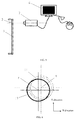
- FIG. 5 is a device which is applied in the method for adjusting the optical centre according to an illustrative embodiment.
- the present embodiment is explained mainly depending on FIG.5 , but FIG. 2-FIG. 9 may be also referred to.
- the device includes a projector 7, a computer 6, and an adjusting assembly 5 (see FIG. 7 ).
- the projector 7 is to obtain an orthography of a camera 3 and an appearance window 4 (see FIG. 2 ) in a main view direction, and transmit the orthography to the computer 6.
- the computer 6 sets an adjusting target 10 (see FIG. 6 ) and an adjusting area 11 (see FIG. 6 ) in accordance with the obtained orthography of the camera 3 and the appearance window 4 (see FIG. 2 ).
- the adjusting assembly 5 (see FIG. 7 ) is to adjust the actual position of the camera 3.
- each cellphone could achieve an excellent centering effect without scrapping, and the problem of high rejection rate due to a serious concentricity deviation between the optical centre 8 of the camera (see FIG. 6 ) and the centre 9 of the appearance window (see FIG. 6 ) mentioned in the Background may be solved.
- the device in the present disclosure could provide an ease in operation, and each cellphone can achieve an excellent centering effect through the device in the present disclosure.
- the adjusting assembly 5 includes two groups, i.e., an X-direction adjusting assembly 5A and a Y-direction adjusting assembly 5B.
- the adjusting assembly 5, i.e., the X-direction adjusting assembly 5A and the Y-direction adjusting assembly 5B are arranged with respect to a horizontal axis and a vertical axis of the optical centre 8 of the camera.
- the adjusting assembly 5, i.e., the X-direction adjusting assembly 5A and the Y-direction adjusting assembly 5B are arranged adjacent to the camera 3.
- the adjusting assembly 5, i.e., the X-direction adjusting assembly 5A and the Y-direction adjusting assembly 5B contact with the camera 3 respectively.
- Each group of the adjusting assembly i.e., both the X-direction adjusting assembly 5A and the Y-direction adjusting assembly 5B include a screw 51 and an elastic sheet 52.
- the screw 51 is fixed in a housing 1. With reference to FIG. 8 , the screw 51 could implement a Z-direction movement with respect to the camera 3.
- an interference amount between a front end of the screw 51 and the elastic sheet 52 changes, which pushes the elastic sheet 52 to deform and restore, thereby adjusting the actual position of the camera 3.
- the elastic sheet 52 has a U-shape on the whole.
- One end of the elastic sheet 52 is fixed at the housing 1, and the other end of which presses against the camera 3.
- a middle portion of the elastic sheet 52 contacts with the screw 51.
- the camera 3 moves toward the right side along the X-direction when screwing in the screw 51. Conversely, the camera 3 moves toward the left side along the X-direction when screwing out the screw 51.
- the "left” and “right” in the present embodiment is the left and right defined on the basis of FIG. 8 .
- the X-direction adjusting assembly 5A and the Y-direction adjusting assembly 5B are adjusted until the adjusting target 10 is located within the adjusting area 11 as shown in FIG. 9 , thereby achieving the required concentricity between the optical centre 8 of the camera and the centre 9 of the appearance window.
- serial numbers of the above embodiments of the present disclosure are only used for depiction, but not for indicating the superiority and inferiority of the embodiments.
Landscapes
- Engineering & Computer Science (AREA)
- Physics & Mathematics (AREA)
- Signal Processing (AREA)
- General Physics & Mathematics (AREA)
- Multimedia (AREA)
- Health & Medical Sciences (AREA)
- Biomedical Technology (AREA)
- General Health & Medical Sciences (AREA)
- Optics & Photonics (AREA)
- Chemical & Material Sciences (AREA)
- Analytical Chemistry (AREA)
- Theoretical Computer Science (AREA)
- Computer Vision & Pattern Recognition (AREA)
- Lens Barrels (AREA)
- Studio Devices (AREA)
- Length Measuring Devices By Optical Means (AREA)
- Accessories Of Cameras (AREA)
- Camera Bodies And Camera Details Or Accessories (AREA)
- Testing, Inspecting, Measuring Of Stereoscopic Televisions And Televisions (AREA)
- Telephone Function (AREA)
Abstract
Description
- This application is based on and claims priority from Chinese Patent Application No.
201310331948.0, filed on August 1, 2013 - The present disclosure relates to the field of mobile communication, and more particularly, to a method and a device for adjusting an optical centre.
- The mobile phone is generally referred to as cellphone, and camera is a standard configuration widely applied to a variety of mobile phones. The camera is categorized into two types: front camera and rear camera which are arranged at a front surface and a rear surface of the cellphone respectively. The front camera is used to take self-portraits and implement conference meetings, whereas the rear camera is used for regular photography. The rear camera is taken as an example to be explained as follows.
- In the rear camera, both a window cover lens and the camera are arranged at a front housing, and both of them are positioned by their individual overall dimensions. The window cover lens is a protective glass of a touch screen, and is printed thereon with a display screen area, a camera area, an Icon area, etc., wherein the camera area is also called as an appearance window. With the user's increasing requirement for the mobile phone appearance, there is a higher demand in the required concentricity between the optical centre of the camera and the centre of the appearance window. Moreover, there are more and more negative user experiences because of camera deviation, i.e., inconcentricity.
- With the restriction by the above techniques, and the unavoidable machining tolerance of each component during the processing, in order to avoid the phenomenon of a serious concentricity deviation between the optical centre of the camera and the centre of the appearance window, it is necessary to increase the machining accuracy and decrease the machining tolerance. The phenomenon of concentricity deviation can be only reduced, but can not be avoided. In a mass production processing, there shows specific regularities of distribution suggesting that some products machined have an excellent yield rate; instead, others may not be well. Once the assembling is completed, the status of the concentricity deviation is fixed and cannot be adjusted. Those products only have to be scraped or remanufactured when there has a high concentricity deviation, which will cause a high rejection rate.
- In order to solve the problem of high rejection rate due to a serious concentricity deviation between the optical centre of the camera and the centre of the appearance window mentioned in the Background, the embodiments of the present disclosure provide a method and a device for adjusting an optical centre. The technical solutions are disclosed as follows.
- According to a first aspect of the embodiments of the present disclosure, there is provided a method for adjusting an optical centre, the method is a step of adjusting a position of a camera, which is additionally performed after fixedly installing a window cover lens and pre-installing the camera, the step of adjusting the position of the camera is to adjust a position of an optical centre of the camera on the basis of a centre of an appearance window on the window cover lens, so as to achieve a required concentricity between the optical centre of the camera and the centre of the appearance window.
- Preferably in the present embodiment, the step of adjusting the position of the camera includes:
-
step 100, obtaining an orthography of the camera and the appearance window in a main view direction; -
step 200, setting an adjusting target and an adjusting area in accordance with the orthography of the camera and the appearance window; and -
step 300, adjusting an actual position of the camera in accordance with a distinction between the adjusting target and the adjusting area so as to make the adjusting target to be located in the adjusting area, whereby achieving the required concentricity between the optical centre of the camera and the centre of the appearance window. - Preferably in the present embodiment, in the
step 100, an orthography of the optical centre of the camera and an outer diameter of the camera in a main view direction is obtained, and an orthography of the centre of the appearance window and an outer diameter of the appearance window in the main view direction is obtained. - Preferably in the present embodiment, in the
step 200, the adjusting target is a circle which is concentric with the orthography of the optical centre of the camera in the main view direction, and a diameter of the circle is equal to the outer diameter of the appearance window; and the adjusting area is a circular ring which is concentric with the orthography of the centre of the appearance window in the main view direction, and an outer diameter and an interior diameter of the circular ring are respectively positive and negative position tolerance values of the outer diameter of the appearance window. - Preferably in the present embodiment, in the
step 300, an actual X-direction position and Y-direction position of the camera are adjusted in accordance with a distinction between the circle and the circular ring, until the cycle is located within an area of the circular ring. - Preferably in the present embodiment, in the
step 200, the adjusting target is a circle which is concentric with the orthography of the optical centre of the camera in the main view direction, and the diameter of the circle is equal to the outer diameter of the camera; and the adjusting area is a circular ring which is concentric with the orthography of the centre of the appearance window in the main view direction, and an outer diameter and an interior diameter of the circular ring are respectively positive and negative position tolerance values of the outer diameter of the camera. - Preferably in the present embodiment, in the
step 300, an actual X-direction position and Y-direction position of the camera are adjusted in accordance with a distinction between the circle and the circular ring until the cycle is located within an area of the circular ring. - According to a second aspect of the embodiments of the present disclosure, there is provided a device according to the method for adjusting the optical centre, the device includes: a projector, a computer, and an adjusting assembly, wherein the projector obtains the orthography of the camera and the appearance window in the main view direction; the computer sets the adjusting target and the adjusting area in accordance with the obtained orthography of the camera and the appearance window; and the adjusting assembly adjusts the actual position of the camera.
- Preferably in the present embodiment, the adjusting assembly includes two groups, the two groups of the adjusting assembly are arranged with respect to a horizontal axis and a vertical axis of the optical centre of the camera, the two groups of the adjusting assembly are arranged adjacent to the camera, the two groups of the adjusting assembly contact with the camera.
- Each group of the adjusting assembly includes a screw and an elastic sheet, the screw is fixed in a housing, the screw implements a Z-direction movement with respect to the camera, and when screwing in or out the screw, the elastic sheet is pushed to deform and restore, thereby adjusting the actual position of the camera.
- Preferably in the present embodiment, the elastic sheet has a U shape on the whole, one end of the elastic sheet is fixed at the housing, the other end of the elastic sheet presses against the camera, and a middle portion of the elastic sheet contacts with the screw.
- The technical solutions provided by the embodiments of the present disclosure may have the following beneficial effects:
- The method provided by the embodiments in the present disclosure may achieve the required concentricity between the optical centre of the camera and the centre of the appearance window by additionally implementing the step of adjusting the position of the camera after fixedly installing the window cover lens and pre-installing the camera. Hence, each cellphone could achieve an excellent centering effect without scrapping, and the problem of high rejection rate due to a serious concentricity deviation between the optical centre of the camera and the centre of the appearance window mentioned in the Background may be solved.
- In addition, the device in the embodiments of the present disclosure has the advantage of ease in operation, and each cellphone can achieve an excellent centering performance through the device.
- Furthermore, the present disclosure is not limited to the front camera, and also may be applied to the rear camera.
- It should be understood that both the foregoing general description and the following detailed description are exemplary and explanatory only and are not restrictive of the present disclosure, as claimed.
- In order to explain the technical solutions in the embodiments of the present disclosure more apparently, a simple introduction to the drawings required for describing the embodiments will be given below. Obviously, the drawings described below only illustrate some embodiments of the present disclosure, and for those skilled in the art, other drawings may be obtained based on these drawings without inventive labor.
-
FIG. 1 is a flow chart of a method for adjusting an optical centre according to an embodiment of the present disclosure; -
FIG. 2 is a front view of a cellphone according to an embodiment of the present disclosure; -
FIG. 3 is a side view of the cellphone according to the embodiment of the present disclosure; -
FIG. 4 is a back view showing that an adjusting assembly is applied to the cellphone according to an embodiment of the present disclosure; -
FIG. 5 is a structural schematic diagram showing that a device is applied to the cellphone according to an embodiment of the present disclosure; -
FIG. 6 is a view showing a state of an adjusting target and an adjusting area before implementing an adjustment according to an embodiment of the present disclosure; -
FIG. 7 is an enlarged view of the adjusting assembly and a camera according to an embodiment of the present disclosure; -
FIG. 8 is a view along a A-direction without the adjusting assembly arranged along a Y-direction inFIG. 7 ; -
FIG. 9 is a view showing a state of the adjusting target and the adjusting area after implementing the adjustment according to the embodiment of the present disclosure. - The meanings indicated by the signs shown in
FIGs. 2-9 are as follows: - 1 housing; 2 window cover lens; 3 camera; 4 appearance window; 5 adjusting assembly; 5A X-direction adjusting assembly; 5B Y-direction adjusting assembly; 51 screw; 52 elastic sheet; 6 computer; 7 projector; 8 optical centre of camera; 9 centre of appearance window; 10 adjusting target; 11 adjusting area.
- These drawings are incorporated into and constitute a part of the specification, illustrate embodiments in accordance with the present disclosure, and serve to explain the principle of the present disclosure together with the description.
- In order to make the purposes, the technical solutions and the advantages of the present disclosure more apparent, the embodiments of the present disclosure will be further described in detail below with reference to the accompanying drawings.
-
FIG. 1 is a flow chart of a method for adjusting an optical centre according to an embodiment of the present disclosure. The present embodiment is mainly explained by usingFIG. 1 , butFIGs. 2-11 may also be referred to. The description to the present embodiment is given by taking a cellphone with a camera 3 (seeFIG. 2 ) located at the rear side of the cellphone as an example. The method is a step of adjusting a position of the camera 3 (seeFIG. 2 ), which is additionally performed after fixedly installing a window cover lens 2 (seeFIG. 3 ) and pre-installing the camera 3 (seeFIG. 2 ). The step of adjusting the position of the camera 3 (seeFIG. 2 ) is to adjust the position of an optical centre of the camera 3 (seeFIG. 2 ) on the basis of a centre 9 of an appearance window (seeFIG. 6 ) on the window cover lens 2 (seeFIG. 3 ), so as to satisfy a required concentricity between the optical centre 8 of the camera (seeFIG. 6 ) and the centre 9 of the appearance window (seeFIG. 6 ). - The method in the present disclosure achieves the required concentricity between the optical centre of the camera 3 (see
FIG. 3 ) and the centre 9 of the appearance window by additionally implementing the step of adjusting the position of the camera 3 (seeFIG. 3 ) after fixedly installing the window cover lens 2 (seeFIG. 3 ) and pre-installing the camera 3 (seeFIG. 3 ). Hence, each cellphone could achieve an excellent centering effect without scrapping, and the problem of high rejection rate due to a serious concentricity deviation between the optical centre 8 of the camera (seeFIG. 6 ) and the centre 9 of the appearance window (seeFIG. 6 ) mentioned in the Background may be solved. - Apparently, the person skilled in the art could understand that the present disclosure is not limited to the rear camera 3 (see
FIG. 3 ), and could also be applied to a front camera 3 (seeFIG. 3 ). -
FIG. 1 is a flow chart of a method for adjusting an optical centre according to an embodiment of the present disclosure. The step of adjusting the position of thecamera 3 includes the following steps. - In
step 100, referring toFIG. 5 , an orthography of thecamera 3 and the appearance window 4 (seeFIG. 2 ) in a main view direction is obtained. - In
step 200, referring toFIG. 6 , an adjustingtarget 10 and an adjustingarea 11 are set in accordance with the obtained orthography of the camera 3 (seeFIG. 2 ) and the appearance window 4 (seeFIG. 2 ). - In
step 300, referring toFIG 6 , an actual position of the camera 3 (seeFIG. 7 ) is adjusted in accordance with a distinction between the adjustingtarget 10 and the adjustingarea 11, such that the adjustingtarget 10 is located within the adjustingarea 11 as shown inFIG. 9 , thereby satisfying the required concentricity between the optical centre 8 of the camera and the centre 9 of the appearance window. - Referring to
FIG. 1 , for instance, in thestep 100, the orthography of the optical centre 8 of the camera and an outer diameter of the camera 3 (seeFIG. 2 ) in the main view direction is obtained, and the orthography of the centre 9 of the appearance window and an outer diameter of the appearance window 4 (seeFIG. 2 ) in the main view direction is obtained. - For instance, as shown in
FIG. 6 , in thestep 200, the adjustingtarget 10 is a circle which is concentric with the orthography of the optical centre 8 of the camera in the main view direction, and a diameter of the circle is equal to the outer diameter of the appearance window 4 (seeFIG. 2 ). The adjustingarea 11 is a circular ring which is concentric with the orthography of the centre 9 of the appearance window in the main view direction, and an outer diameter and an interior diameter of the circular ring are respectively positive and negative position tolerance values of the outer diameter of the appearance window 4 (seeFIG. 2 ). - Still referring to
FIG. 6 , in thestep 300, the actual X-direction position and Y-direction position of the camera 3 (seeFIG. 7 ) are adjusted as shown inFIG. 9 , in accordance with a distinction between the circle and the circular ring, until the cycle is located within an area o f the circular ring. - As shown in
FIG. 6 , in thestep 200, the adjustingtarget 10 is a circle which is concentric with the orthography of the optical centre 8 of the camera in the main view direction, and the diameter of the circle is equal to the outer diameter of the camera 3 (seeFIG. 2 ). The adjustingarea 11 is a circular ring which is concentric with the orthography of the centre 9 of the appearance window in the main view direction, and an outer diameter and an interior diameter of the circular ring are respectively positive and negative position tolerance values of the outer diameter of the camera 3 (seeFIG. 3 ). - Referring to
FIG. 6 , in thestep 300, the actual X-direction position and Y-direction position of the camera 3 (seeFIG. 7 ) are adjusted as shown inFIG. 9 , in accordance with a distinction between the circle and the circular ring, until the cycle is located within an area of the circular ring. -
FIG. 5 is a device which is applied in the method for adjusting the optical centre according to an illustrative embodiment. The present embodiment is explained mainly depending onFIG.5 , butFIG. 2-FIG. 9 may be also referred to. The device includes a projector 7, a computer 6, and an adjusting assembly 5 (seeFIG. 7 ). The projector 7 is to obtain an orthography of acamera 3 and an appearance window 4 (seeFIG. 2 ) in a main view direction, and transmit the orthography to the computer 6. The computer 6 sets an adjusting target 10 (seeFIG. 6 ) and an adjusting area 11 (seeFIG. 6 ) in accordance with the obtained orthography of thecamera 3 and the appearance window 4 (seeFIG. 2 ). The adjusting assembly 5 (seeFIG. 7 ) is to adjust the actual position of thecamera 3. - With the device in the present disclosure, each cellphone could achieve an excellent centering effect without scrapping, and the problem of high rejection rate due to a serious concentricity deviation between the optical centre 8 of the camera (see
FIG. 6 ) and the centre 9 of the appearance window (seeFIG. 6 ) mentioned in the Background may be solved. Also, the device in the present disclosure could provide an ease in operation, and each cellphone can achieve an excellent centering effect through the device in the present disclosure. - Apparently, the person skilled in the art could understand that the present disclosure is not limited to the rear camera 3 (see
FIG. 3 ), and could also be applied to a front camera. - For instance, as shown in
FIG. 7 , the adjustingassembly 5 includes two groups, i.e., an X-direction adjusting assembly 5A and a Y-direction adjusting assembly 5B. The adjustingassembly 5, i.e., the X-direction adjusting assembly 5A and the Y-direction adjusting assembly 5B are arranged with respect to a horizontal axis and a vertical axis of the optical centre 8 of the camera. The adjustingassembly 5, i.e., the X-direction adjusting assembly 5A and the Y-direction adjusting assembly 5B are arranged adjacent to thecamera 3. The adjustingassembly 5, i.e., the X-direction adjusting assembly 5A and the Y-direction adjusting assembly 5B contact with thecamera 3 respectively. - Each group of the adjusting assembly, i.e., both the X-direction adjusting assembly 5A and the Y-
direction adjusting assembly 5B include ascrew 51 and anelastic sheet 52. Thescrew 51 is fixed in a housing 1. With reference toFIG. 8 , thescrew 51 could implement a Z-direction movement with respect to thecamera 3. When screwing in or out thescrew 51, an interference amount between a front end of thescrew 51 and theelastic sheet 52 changes, which pushes theelastic sheet 52 to deform and restore, thereby adjusting the actual position of thecamera 3. - In the present embodiment, as shown in
FIG. 8 , theelastic sheet 52 has a U-shape on the whole. One end of theelastic sheet 52 is fixed at the housing 1, and the other end of which presses against thecamera 3. In addition, a middle portion of theelastic sheet 52 contacts with thescrew 51. - In the present embodiment, the
camera 3 moves toward the right side along the X-direction when screwing in thescrew 51. Conversely, thecamera 3 moves toward the left side along the X-direction when screwing out thescrew 51. The "left" and "right" in the present embodiment is the left and right defined on the basis ofFIG. 8 . - With reference to
FIG. 8 , the X-direction adjusting assembly 5A and the Y-direction adjusting assembly 5B are adjusted until the adjustingtarget 10 is located within the adjustingarea 11 as shown inFIG. 9 , thereby achieving the required concentricity between the optical centre 8 of the camera and the centre 9 of the appearance window. - The serial numbers of the above embodiments of the present disclosure are only used for depiction, but not for indicating the superiority and inferiority of the embodiments.
- The above depictions are only for the preferred embodiments of the present disclosure, which are not used to limit the present disclosure. Any variations, equivalent substitutions, and improvements made within the spirit and principles of the present disclosure shall be encompassed within the scope of the present disclosure.
Claims (10)
- A method for adjusting an optical centre, characterized in that the method is a step of adjusting a position of a camera, which is additionally performed after fixedly installing a window cover lens and pre-installing the camera, the step of adjusting the position of the camera is to adjust a position of an optical centre of the camera on the basis of a centre of an appearance window on the window cover lens, so as to achieve a required concentricity between the optical centre of the camera and the centre of the appearance window.
- The method as claimed in claim 1, characterized in that said step of adjusting the position of the camera comprises:step 100, obtaining an orthography of the camera and the appearance window in a main view direction;step 200, setting an adjusting target and an adjusting area in accordance with the orthography of the camera and the appearance window; andstep 300, adjusting an actual position of the camera in accordance with a distinction between the adjusting target and the adjusting area to make the adjusting target to be located in the adjusting area, whereby achieving the required concentricity between the optical centre of the camera and the centre of the appearance window.
- The method as claimed in claim 2, characterized in that in said step 100, an orthography of the optical centre of the camera and an outer diameter of the camera in a main view direction is obtained, and an orthography of the centre of the appearance window and an outer diameter of the appearance window in the main view direction is obtained.
- The method as claimed in claim 3, characterized in that in said step 200, the adjusting target is a circle which is concentric with the orthography of the optical centre of the camera in the main view direction, and a diameter of the circle is equal to the outer diameter of the appearance window; and the adjusting area is a circular ring which is concentric with the orthography of the centre of the appearance window in the main view direction, and an outer diameter and an interior diameter of the circular ring are respectively positive and negative position tolerance values of the outer diameter of the appearance window.
- The method as claimed in claim 4, characterized in that in said step 300, an actual X-direction position and Y-direction position of the camera are adjusted in accordance with a distinction between the circle and the circular ring, until the cycle is located within an area of the circular ring.
- The method as claimed in claim 3, characterized in that in said step 200, the adjusting target is a circle which is concentric with the orthography of the optical centre of the camera in the main view direction, and the diameter of the circle is equal to the outer diameter of the camera; and the adjusting area is a circular ring which is concentric with the orthography of the centre of the appearance window in the main view direction, and an outer diameter and an interior diameter of the circular ring are respectively positive and negative position tolerance values of the outer diameter of the camera.
- The method as claimed in claim 6, characterized in that in said step 300, an actual X-direction position and Y-direction position of the camera are adjusted in accordance with a distinction between the circle and the circular ring until the cycle is located within an area of the circular ring.
- A device for the method for adjusting the optical centre as claimed in any one of claims 2-7, characterized in that said device comprises a projector, a computer, and an adjusting assembly, wherein
the projector obtains the orthography of the camera and the appearance window in the main view direction;
the computer sets the adjusting target and the adjusting area in accordance with the obtained orthography of the camera and the appearance window; and
the adjusting assembly adjusts the actual position of the camera. - The device as claimed in claim 8, characterized in that the adjusting assembly comprises two groups, the two groups of the adjusting assembly are arranged with respect to a horizontal axis and a vertical axis of the optical centre of the camera, the two groups of the adjusting assembly are arranged adjacent to the camera, the two groups of the adjusting assembly contact with the camera,
wherein each group of the adjusting assembly comprises a screw and an elastic sheet, the screw is fixed in a housing, the screw implements a Z-direction movement with respect to the camera, and when screwing in or out the screw, the elastic sheet is pushed to deform and restore, thereby adjusting the actual position of the camera. - The device as claimed in claim 9, characterized in that the elastic sheet has a U shape on the whole, one end of the elastic sheet is fixed at the housing, the other end of the elastic sheet presses against the camera, and a middle portion of the elastic sheet contacts with the screw.
Applications Claiming Priority (2)
| Application Number | Priority Date | Filing Date | Title |
|---|---|---|---|
| CN201310331948.0A CN103402116B (en) | 2013-08-01 | 2013-08-01 | A kind of optical center calibration method and device |
| PCT/CN2014/072283 WO2015014119A1 (en) | 2013-08-01 | 2014-02-20 | Optical center calibration method and device |
Publications (3)
| Publication Number | Publication Date |
|---|---|
| EP3029914A1 true EP3029914A1 (en) | 2016-06-08 |
| EP3029914A4 EP3029914A4 (en) | 2017-03-29 |
| EP3029914B1 EP3029914B1 (en) | 2019-08-28 |
Family
ID=49565622
Family Applications (1)
| Application Number | Title | Priority Date | Filing Date |
|---|---|---|---|
| EP14831240.8A Active EP3029914B1 (en) | 2013-08-01 | 2014-02-20 | Optical center calibration method and device |
Country Status (9)
| Country | Link |
|---|---|
| US (1) | US9549117B2 (en) |
| EP (1) | EP3029914B1 (en) |
| JP (1) | JP6228987B2 (en) |
| KR (1) | KR101670466B1 (en) |
| CN (1) | CN103402116B (en) |
| BR (1) | BR112015015296A2 (en) |
| MX (1) | MX345774B (en) |
| RU (1) | RU2615792C2 (en) |
| WO (1) | WO2015014119A1 (en) |
Cited By (1)
| Publication number | Priority date | Publication date | Assignee | Title |
|---|---|---|---|---|
| US12432290B2 (en) | 2021-10-07 | 2025-09-30 | Samsung Electronics Co., Ltd. | Electronic device with camera module and sliding assembly |
Families Citing this family (14)
| Publication number | Priority date | Publication date | Assignee | Title |
|---|---|---|---|---|
| CN103402116B (en) | 2013-08-01 | 2016-01-13 | 小米科技有限责任公司 | A kind of optical center calibration method and device |
| CN104197830B (en) * | 2014-08-06 | 2017-04-19 | 青岛歌尔声学科技有限公司 | Method and system for correcting optical test fixture |
| CN105965250B (en) * | 2016-04-21 | 2018-05-25 | 珠海上富电技股份有限公司 | Camera central shaft adjusting machine |
| CN107492126B (en) * | 2017-08-03 | 2019-11-05 | 厦门云感科技有限公司 | Calibration method, device, system, medium and the equipment of camera central axis |
| CN107707906B (en) * | 2017-09-29 | 2019-06-25 | 中国科学院长春光学精密机械与物理研究所 | A kind of the ground caliberating device and method of optical lens defocusing amount under high altitude conditions |
| CN110824722B (en) * | 2018-08-07 | 2021-10-15 | 宁波舜宇光电信息有限公司 | Structured light projection module assembly device and projection module assembly and detection method |
| CN111355873B (en) * | 2018-12-21 | 2022-03-11 | 余姚舜宇智能光学技术有限公司 | Camera module assembly method |
| CN110248183A (en) * | 2019-05-31 | 2019-09-17 | 广州聚美视觉科技有限公司 | A kind of camera optical center test method |
| CN110262058B (en) * | 2019-06-19 | 2021-11-23 | 中国工程物理研究院应用电子学研究所 | Auxiliary pupil optical axis adjusting device and method |
| CN111708172B (en) * | 2020-05-08 | 2022-06-21 | 宁波傲视智绘光电科技有限公司 | Light spot position adjusting method and system of laser emitting end |
| RU2749180C1 (en) * | 2020-09-25 | 2021-06-07 | Федеральное государственное унитарное предприятие "Центральный аэрогидродинамический институт имени профессора Н.Е. Жуковского" (ФГУП "ЦАГИ") | Optical device for determining the displacement relative to each other of holes of adjacent surfaces |
| US11277941B1 (en) | 2020-10-02 | 2022-03-15 | Google Llc | Thermal-control system of a video-recording doorbell and associated video-recording doorbells |
| JP7692476B2 (en) | 2020-10-02 | 2025-06-13 | グーグル エルエルシー | Image capture doorbell device |
| EP4381729A1 (en) | 2021-08-02 | 2024-06-12 | Google LLC | Asymmetric camera sensor positioning for enhanced package detection |
Family Cites Families (31)
| Publication number | Priority date | Publication date | Assignee | Title |
|---|---|---|---|---|
| JPH0453912A (en) * | 1990-06-22 | 1992-02-21 | Nec Corp | Optical axis aligning method for photodetecting module |
| JP3208902B2 (en) * | 1993-03-11 | 2001-09-17 | ミノルタ株式会社 | Lens system optical axis adjusting device and lens system optical axis adjusting method |
| JP3376069B2 (en) * | 1993-12-30 | 2003-02-10 | キヤノン株式会社 | Ophthalmic equipment |
| JPH087769A (en) * | 1994-06-15 | 1996-01-12 | Hitachi Ltd | Color CRT Color Purity Adjuster |
| JP2000149472A (en) * | 1998-11-07 | 2000-05-30 | Mitsubishi Electric Corp | Magnetic disk drive and method of manufacturing the same |
| JP4354076B2 (en) * | 2000-03-13 | 2009-10-28 | オリンパス株式会社 | Image frame centering adjustment method and imaging apparatus |
| US7016551B1 (en) * | 2000-04-10 | 2006-03-21 | Fuji Xerox Co., Ltd. | Image reader |
| TW476216B (en) * | 2000-08-25 | 2002-02-11 | Elecvision Inc | Method for positioning image in a digital image capturing device |
| TW512478B (en) * | 2000-09-14 | 2002-12-01 | Olympus Optical Co | Alignment apparatus |
| JP2004287304A (en) * | 2003-03-25 | 2004-10-14 | Nidec Copal Corp | Imaging device mounting apparatus |
| US7539340B2 (en) * | 2003-04-25 | 2009-05-26 | Topcon Corporation | Apparatus and method for three-dimensional coordinate measurement |
| JP2005276639A (en) * | 2004-03-25 | 2005-10-06 | Jeol Ltd | Method for adjusting position of objective lens diaphragm in scanning electron beam apparatus |
| US7773799B2 (en) * | 2004-04-02 | 2010-08-10 | The Boeing Company | Method for automatic stereo measurement of a point of interest in a scene |
| JP2006157736A (en) * | 2004-11-30 | 2006-06-15 | Seiko Precision Inc | Imaging module |
| KR100741733B1 (en) * | 2005-05-10 | 2007-07-23 | 엠텍비젼 주식회사 | Lens center positioning method and imaging device performing the method |
| KR100723218B1 (en) * | 2005-12-09 | 2007-05-29 | 삼성전기주식회사 | Camera module with improved optical axis alignment |
| US7727009B2 (en) * | 2007-02-15 | 2010-06-01 | Tyco Electronics Canada Ulc | Panel mount light emitting element assembly |
| JP2008209662A (en) * | 2007-02-26 | 2008-09-11 | Nec Saitama Ltd | Electronic device having lens unit mounting structure and photographing function in electronic device |
| WO2009069925A1 (en) * | 2007-11-30 | 2009-06-04 | Nanophotonics Co., Ltd. | Lens holder capable of adjusting location of optical axis of lens |
| CN101459102B (en) * | 2007-12-13 | 2010-08-11 | 中芯国际集成电路制造(上海)有限公司 | Wafer positioning method |
| US8060330B2 (en) * | 2008-12-12 | 2011-11-15 | Lam Research Corporation | Method and system for centering wafer on chuck |
| JP2011112880A (en) * | 2009-11-27 | 2011-06-09 | Nikon Corp | microscope |
| US8610822B2 (en) * | 2010-04-19 | 2013-12-17 | Apple Inc. | Camera alignment and mounting structures |
| CN201757830U (en) * | 2010-07-14 | 2011-03-09 | 张承权 | Camera detecting device capable of rapidly aligning to central position |
| US8467177B2 (en) * | 2010-10-29 | 2013-06-18 | Apple Inc. | Displays with polarizer windows and opaque masking layers for electronic devices |
| US9124873B2 (en) * | 2010-12-08 | 2015-09-01 | Cognex Corporation | System and method for finding correspondence between cameras in a three-dimensional vision system |
| CN201994977U (en) * | 2011-01-12 | 2011-09-28 | 深圳市同洲电子股份有限公司 | Device for accepting front camera and mobile terminal |
| JP2013142850A (en) * | 2012-01-12 | 2013-07-22 | Seiko Epson Corp | Fixation member of optical component and projector |
| CN102810205B (en) * | 2012-07-09 | 2015-08-05 | 深圳泰山在线科技有限公司 | The scaling method of a kind of shooting or photographic means |
| CN203086550U (en) * | 2013-03-25 | 2013-07-24 | 广东欧珀移动通信有限公司 | Assembly structure of mobile phone camera |
| CN103402116B (en) * | 2013-08-01 | 2016-01-13 | 小米科技有限责任公司 | A kind of optical center calibration method and device |
-
2013
- 2013-08-01 CN CN201310331948.0A patent/CN103402116B/en active Active
-
2014
- 2014-02-20 MX MX2015007005A patent/MX345774B/en active IP Right Grant
- 2014-02-20 JP JP2015543297A patent/JP6228987B2/en active Active
- 2014-02-20 WO PCT/CN2014/072283 patent/WO2015014119A1/en not_active Ceased
- 2014-02-20 RU RU2015122142A patent/RU2615792C2/en active
- 2014-02-20 EP EP14831240.8A patent/EP3029914B1/en active Active
- 2014-02-20 KR KR1020157014032A patent/KR101670466B1/en active Active
- 2014-02-20 BR BR112015015296A patent/BR112015015296A2/en active Search and Examination
- 2014-04-29 US US14/264,063 patent/US9549117B2/en active Active
Cited By (1)
| Publication number | Priority date | Publication date | Assignee | Title |
|---|---|---|---|---|
| US12432290B2 (en) | 2021-10-07 | 2025-09-30 | Samsung Electronics Co., Ltd. | Electronic device with camera module and sliding assembly |
Also Published As
| Publication number | Publication date |
|---|---|
| JP6228987B2 (en) | 2017-11-08 |
| KR101670466B1 (en) | 2016-10-27 |
| BR112015015296A2 (en) | 2017-07-11 |
| MX2015007005A (en) | 2015-09-28 |
| CN103402116A (en) | 2013-11-20 |
| MX345774B (en) | 2017-02-14 |
| RU2615792C2 (en) | 2017-04-11 |
| KR20150079878A (en) | 2015-07-08 |
| EP3029914A4 (en) | 2017-03-29 |
| EP3029914B1 (en) | 2019-08-28 |
| RU2015122142A (en) | 2017-01-10 |
| WO2015014119A1 (en) | 2015-02-05 |
| JP2016505875A (en) | 2016-02-25 |
| CN103402116B (en) | 2016-01-13 |
| US20150036036A1 (en) | 2015-02-05 |
| US9549117B2 (en) | 2017-01-17 |
Similar Documents
| Publication | Publication Date | Title |
|---|---|---|
| EP3029914B1 (en) | Optical center calibration method and device | |
| US11095812B2 (en) | Image processing method, apparatus, and device | |
| CN205210492U (en) | Lens module | |
| US9746635B2 (en) | Lens module | |
| TWI623787B (en) | Imaging lens set with plastic lens element, imaging lens module and electronic device | |
| US9817205B2 (en) | Lens module | |
| US9746634B2 (en) | Lens module | |
| CN107343066B (en) | Cameras and Terminals | |
| US20150323756A1 (en) | Optical lens and a method for manufacturing the same | |
| CN106662724A (en) | Mobile terminal | |
| TW201901211A (en) | Secondary molded ring-shaped optical element, imaging lens set, imaging device, and electronic device | |
| US20200057237A1 (en) | Lens module | |
| CN211263914U (en) | Optical lenses, cameras and mobile terminals | |
| CN210016495U (en) | Mobile terminal | |
| US20170139173A1 (en) | Lens Module | |
| TW202014752A (en) | Imaging lens assembly with metal retainer, camera module including same assembly and electronic device including same module | |
| CN110278359A (en) | Electronic device and method of assembling the same | |
| CN110312012A (en) | Electronic equipment | |
| CN115412653A (en) | Optical lens and camera module | |
| WO2020259404A1 (en) | Cover plate assembly, display device, and electronic equipment | |
| CN206339747U (en) | Camera lens module | |
| CN216052402U (en) | Macro lens module, image acquisition device and mobile terminal | |
| CN204613480U (en) | For many eyeglasses camera lens of mobile communication terminal | |
| CN209964154U (en) | Electronic device | |
| CN219162456U (en) | Multi-aperture lens structure |
Legal Events
| Date | Code | Title | Description |
|---|---|---|---|
| PUAI | Public reference made under article 153(3) epc to a published international application that has entered the european phase |
Free format text: ORIGINAL CODE: 0009012 |
|
| 17P | Request for examination filed |
Effective date: 20160301 |
|
| AK | Designated contracting states |
Kind code of ref document: A1 Designated state(s): AL AT BE BG CH CY CZ DE DK EE ES FI FR GB GR HR HU IE IS IT LI LT LU LV MC MK MT NL NO PL PT RO RS SE SI SK SM TR |
|
| AX | Request for extension of the european patent |
Extension state: BA ME |
|
| DAX | Request for extension of the european patent (deleted) | ||
| A4 | Supplementary search report drawn up and despatched |
Effective date: 20170223 |
|
| RIC1 | Information provided on ipc code assigned before grant |
Ipc: H04M 1/02 20060101AFI20170218BHEP Ipc: H04N 17/00 20060101ALI20170218BHEP |
|
| STAA | Information on the status of an ep patent application or granted ep patent |
Free format text: STATUS: EXAMINATION IS IN PROGRESS |
|
| 17Q | First examination report despatched |
Effective date: 20180328 |
|
| GRAP | Despatch of communication of intention to grant a patent |
Free format text: ORIGINAL CODE: EPIDOSNIGR1 |
|
| STAA | Information on the status of an ep patent application or granted ep patent |
Free format text: STATUS: GRANT OF PATENT IS INTENDED |
|
| INTG | Intention to grant announced |
Effective date: 20190430 |
|
| GRAS | Grant fee paid |
Free format text: ORIGINAL CODE: EPIDOSNIGR3 |
|
| GRAA | (expected) grant |
Free format text: ORIGINAL CODE: 0009210 |
|
| STAA | Information on the status of an ep patent application or granted ep patent |
Free format text: STATUS: THE PATENT HAS BEEN GRANTED |
|
| AK | Designated contracting states |
Kind code of ref document: B1 Designated state(s): AL AT BE BG CH CY CZ DE DK EE ES FI FR GB GR HR HU IE IS IT LI LT LU LV MC MK MT NL NO PL PT RO RS SE SI SK SM TR |
|
| REG | Reference to a national code |
Ref country code: GB Ref legal event code: FG4D |
|
| REG | Reference to a national code |
Ref country code: CH Ref legal event code: EP |
|
| REG | Reference to a national code |
Ref country code: AT Ref legal event code: REF Ref document number: 1173857 Country of ref document: AT Kind code of ref document: T Effective date: 20190915 |
|
| REG | Reference to a national code |
Ref country code: IE Ref legal event code: FG4D |
|
| REG | Reference to a national code |
Ref country code: DE Ref legal event code: R096 Ref document number: 602014052688 Country of ref document: DE |
|
| REG | Reference to a national code |
Ref country code: NL Ref legal event code: MP Effective date: 20190828 |
|
| REG | Reference to a national code |
Ref country code: LT Ref legal event code: MG4D |
|
| PG25 | Lapsed in a contracting state [announced via postgrant information from national office to epo] |
Ref country code: NO Free format text: LAPSE BECAUSE OF FAILURE TO SUBMIT A TRANSLATION OF THE DESCRIPTION OR TO PAY THE FEE WITHIN THE PRESCRIBED TIME-LIMIT Effective date: 20191128 Ref country code: SE Free format text: LAPSE BECAUSE OF FAILURE TO SUBMIT A TRANSLATION OF THE DESCRIPTION OR TO PAY THE FEE WITHIN THE PRESCRIBED TIME-LIMIT Effective date: 20190828 Ref country code: HR Free format text: LAPSE BECAUSE OF FAILURE TO SUBMIT A TRANSLATION OF THE DESCRIPTION OR TO PAY THE FEE WITHIN THE PRESCRIBED TIME-LIMIT Effective date: 20190828 Ref country code: FI Free format text: LAPSE BECAUSE OF FAILURE TO SUBMIT A TRANSLATION OF THE DESCRIPTION OR TO PAY THE FEE WITHIN THE PRESCRIBED TIME-LIMIT Effective date: 20190828 Ref country code: LT Free format text: LAPSE BECAUSE OF FAILURE TO SUBMIT A TRANSLATION OF THE DESCRIPTION OR TO PAY THE FEE WITHIN THE PRESCRIBED TIME-LIMIT Effective date: 20190828 Ref country code: PT Free format text: LAPSE BECAUSE OF FAILURE TO SUBMIT A TRANSLATION OF THE DESCRIPTION OR TO PAY THE FEE WITHIN THE PRESCRIBED TIME-LIMIT Effective date: 20191230 Ref country code: BG Free format text: LAPSE BECAUSE OF FAILURE TO SUBMIT A TRANSLATION OF THE DESCRIPTION OR TO PAY THE FEE WITHIN THE PRESCRIBED TIME-LIMIT Effective date: 20191128 Ref country code: NL Free format text: LAPSE BECAUSE OF FAILURE TO SUBMIT A TRANSLATION OF THE DESCRIPTION OR TO PAY THE FEE WITHIN THE PRESCRIBED TIME-LIMIT Effective date: 20190828 |
|
| PG25 | Lapsed in a contracting state [announced via postgrant information from national office to epo] |
Ref country code: AL Free format text: LAPSE BECAUSE OF FAILURE TO SUBMIT A TRANSLATION OF THE DESCRIPTION OR TO PAY THE FEE WITHIN THE PRESCRIBED TIME-LIMIT Effective date: 20190828 Ref country code: LV Free format text: LAPSE BECAUSE OF FAILURE TO SUBMIT A TRANSLATION OF THE DESCRIPTION OR TO PAY THE FEE WITHIN THE PRESCRIBED TIME-LIMIT Effective date: 20190828 Ref country code: ES Free format text: LAPSE BECAUSE OF FAILURE TO SUBMIT A TRANSLATION OF THE DESCRIPTION OR TO PAY THE FEE WITHIN THE PRESCRIBED TIME-LIMIT Effective date: 20190828 Ref country code: GR Free format text: LAPSE BECAUSE OF FAILURE TO SUBMIT A TRANSLATION OF THE DESCRIPTION OR TO PAY THE FEE WITHIN THE PRESCRIBED TIME-LIMIT Effective date: 20191129 Ref country code: IS Free format text: LAPSE BECAUSE OF FAILURE TO SUBMIT A TRANSLATION OF THE DESCRIPTION OR TO PAY THE FEE WITHIN THE PRESCRIBED TIME-LIMIT Effective date: 20191228 Ref country code: RS Free format text: LAPSE BECAUSE OF FAILURE TO SUBMIT A TRANSLATION OF THE DESCRIPTION OR TO PAY THE FEE WITHIN THE PRESCRIBED TIME-LIMIT Effective date: 20190828 |
|
| REG | Reference to a national code |
Ref country code: AT Ref legal event code: MK05 Ref document number: 1173857 Country of ref document: AT Kind code of ref document: T Effective date: 20190828 |
|
| PG25 | Lapsed in a contracting state [announced via postgrant information from national office to epo] |
Ref country code: TR Free format text: LAPSE BECAUSE OF FAILURE TO SUBMIT A TRANSLATION OF THE DESCRIPTION OR TO PAY THE FEE WITHIN THE PRESCRIBED TIME-LIMIT Effective date: 20190828 |
|
| PG25 | Lapsed in a contracting state [announced via postgrant information from national office to epo] |
Ref country code: IT Free format text: LAPSE BECAUSE OF FAILURE TO SUBMIT A TRANSLATION OF THE DESCRIPTION OR TO PAY THE FEE WITHIN THE PRESCRIBED TIME-LIMIT Effective date: 20190828 Ref country code: RO Free format text: LAPSE BECAUSE OF FAILURE TO SUBMIT A TRANSLATION OF THE DESCRIPTION OR TO PAY THE FEE WITHIN THE PRESCRIBED TIME-LIMIT Effective date: 20190828 Ref country code: DK Free format text: LAPSE BECAUSE OF FAILURE TO SUBMIT A TRANSLATION OF THE DESCRIPTION OR TO PAY THE FEE WITHIN THE PRESCRIBED TIME-LIMIT Effective date: 20190828 Ref country code: PL Free format text: LAPSE BECAUSE OF FAILURE TO SUBMIT A TRANSLATION OF THE DESCRIPTION OR TO PAY THE FEE WITHIN THE PRESCRIBED TIME-LIMIT Effective date: 20190828 Ref country code: EE Free format text: LAPSE BECAUSE OF FAILURE TO SUBMIT A TRANSLATION OF THE DESCRIPTION OR TO PAY THE FEE WITHIN THE PRESCRIBED TIME-LIMIT Effective date: 20190828 Ref country code: AT Free format text: LAPSE BECAUSE OF FAILURE TO SUBMIT A TRANSLATION OF THE DESCRIPTION OR TO PAY THE FEE WITHIN THE PRESCRIBED TIME-LIMIT Effective date: 20190828 |
|
| PG25 | Lapsed in a contracting state [announced via postgrant information from national office to epo] |
Ref country code: CZ Free format text: LAPSE BECAUSE OF FAILURE TO SUBMIT A TRANSLATION OF THE DESCRIPTION OR TO PAY THE FEE WITHIN THE PRESCRIBED TIME-LIMIT Effective date: 20190828 Ref country code: IS Free format text: LAPSE BECAUSE OF FAILURE TO SUBMIT A TRANSLATION OF THE DESCRIPTION OR TO PAY THE FEE WITHIN THE PRESCRIBED TIME-LIMIT Effective date: 20200224 Ref country code: SM Free format text: LAPSE BECAUSE OF FAILURE TO SUBMIT A TRANSLATION OF THE DESCRIPTION OR TO PAY THE FEE WITHIN THE PRESCRIBED TIME-LIMIT Effective date: 20190828 Ref country code: SK Free format text: LAPSE BECAUSE OF FAILURE TO SUBMIT A TRANSLATION OF THE DESCRIPTION OR TO PAY THE FEE WITHIN THE PRESCRIBED TIME-LIMIT Effective date: 20190828 |
|
| REG | Reference to a national code |
Ref country code: DE Ref legal event code: R097 Ref document number: 602014052688 Country of ref document: DE |
|
| PLBE | No opposition filed within time limit |
Free format text: ORIGINAL CODE: 0009261 |
|
| STAA | Information on the status of an ep patent application or granted ep patent |
Free format text: STATUS: NO OPPOSITION FILED WITHIN TIME LIMIT |
|
| PG2D | Information on lapse in contracting state deleted |
Ref country code: IS |
|
| 26N | No opposition filed |
Effective date: 20200603 |
|
| PG25 | Lapsed in a contracting state [announced via postgrant information from national office to epo] |
Ref country code: SI Free format text: LAPSE BECAUSE OF FAILURE TO SUBMIT A TRANSLATION OF THE DESCRIPTION OR TO PAY THE FEE WITHIN THE PRESCRIBED TIME-LIMIT Effective date: 20190828 |
|
| REG | Reference to a national code |
Ref country code: CH Ref legal event code: PL |
|
| REG | Reference to a national code |
Ref country code: BE Ref legal event code: MM Effective date: 20200229 |
|
| PG25 | Lapsed in a contracting state [announced via postgrant information from national office to epo] |
Ref country code: MC Free format text: LAPSE BECAUSE OF FAILURE TO SUBMIT A TRANSLATION OF THE DESCRIPTION OR TO PAY THE FEE WITHIN THE PRESCRIBED TIME-LIMIT Effective date: 20190828 Ref country code: LU Free format text: LAPSE BECAUSE OF NON-PAYMENT OF DUE FEES Effective date: 20200220 |
|
| PG25 | Lapsed in a contracting state [announced via postgrant information from national office to epo] |
Ref country code: LI Free format text: LAPSE BECAUSE OF NON-PAYMENT OF DUE FEES Effective date: 20200229 Ref country code: CH Free format text: LAPSE BECAUSE OF NON-PAYMENT OF DUE FEES Effective date: 20200229 |
|
| PG25 | Lapsed in a contracting state [announced via postgrant information from national office to epo] |
Ref country code: IE Free format text: LAPSE BECAUSE OF NON-PAYMENT OF DUE FEES Effective date: 20200220 |
|
| PG25 | Lapsed in a contracting state [announced via postgrant information from national office to epo] |
Ref country code: BE Free format text: LAPSE BECAUSE OF NON-PAYMENT OF DUE FEES Effective date: 20200229 |
|
| PG25 | Lapsed in a contracting state [announced via postgrant information from national office to epo] |
Ref country code: MT Free format text: LAPSE BECAUSE OF FAILURE TO SUBMIT A TRANSLATION OF THE DESCRIPTION OR TO PAY THE FEE WITHIN THE PRESCRIBED TIME-LIMIT Effective date: 20190828 Ref country code: CY Free format text: LAPSE BECAUSE OF FAILURE TO SUBMIT A TRANSLATION OF THE DESCRIPTION OR TO PAY THE FEE WITHIN THE PRESCRIBED TIME-LIMIT Effective date: 20190828 |
|
| PG25 | Lapsed in a contracting state [announced via postgrant information from national office to epo] |
Ref country code: MK Free format text: LAPSE BECAUSE OF FAILURE TO SUBMIT A TRANSLATION OF THE DESCRIPTION OR TO PAY THE FEE WITHIN THE PRESCRIBED TIME-LIMIT Effective date: 20190828 |
|
| P01 | Opt-out of the competence of the unified patent court (upc) registered |
Effective date: 20230523 |
|
| PGFP | Annual fee paid to national office [announced via postgrant information from national office to epo] |
Ref country code: GB Payment date: 20260224 Year of fee payment: 13 |
|
| PGFP | Annual fee paid to national office [announced via postgrant information from national office to epo] |
Ref country code: DE Payment date: 20260223 Year of fee payment: 13 |
|
| PGFP | Annual fee paid to national office [announced via postgrant information from national office to epo] |
Ref country code: FR Payment date: 20260224 Year of fee payment: 13 |