EP3029568A1 - Remote update of software components - Google Patents
Remote update of software components Download PDFInfo
- Publication number
- EP3029568A1 EP3029568A1 EP15003140.9A EP15003140A EP3029568A1 EP 3029568 A1 EP3029568 A1 EP 3029568A1 EP 15003140 A EP15003140 A EP 15003140A EP 3029568 A1 EP3029568 A1 EP 3029568A1
- Authority
- EP
- European Patent Office
- Prior art keywords
- version
- component type
- software component
- software
- component
- Prior art date
- Legal status (The legal status is an assumption and is not a legal conclusion. Google has not performed a legal analysis and makes no representation as to the accuracy of the status listed.)
- Granted
Links
Images




Classifications
-
- G—PHYSICS
- G06—COMPUTING OR CALCULATING; COUNTING
- G06F—ELECTRIC DIGITAL DATA PROCESSING
- G06F8/00—Arrangements for software engineering
- G06F8/60—Software deployment
- G06F8/65—Updates
-
- G—PHYSICS
- G06—COMPUTING OR CALCULATING; COUNTING
- G06F—ELECTRIC DIGITAL DATA PROCESSING
- G06F8/00—Arrangements for software engineering
- G06F8/60—Software deployment
- G06F8/65—Updates
- G06F8/656—Updates while running
-
- G—PHYSICS
- G06—COMPUTING OR CALCULATING; COUNTING
- G06F—ELECTRIC DIGITAL DATA PROCESSING
- G06F8/00—Arrangements for software engineering
- G06F8/60—Software deployment
- G06F8/61—Installation
- G06F8/62—Uninstallation
-
- H—ELECTRICITY
- H04—ELECTRIC COMMUNICATION TECHNIQUE
- H04L—TRANSMISSION OF DIGITAL INFORMATION, e.g. TELEGRAPHIC COMMUNICATION
- H04L67/00—Network arrangements or protocols for supporting network services or applications
- H04L67/01—Protocols
- H04L67/10—Protocols in which an application is distributed across nodes in the network
Definitions
- processing devices have decreased dramatically in recent years. Consequently, the use of processing devices is envisioned in scenarios which would have previously been cost- or space-prohibitive. In one such scenario, many devices are deployed in different places and operational areas, for example in a collection of processing plants. The primary task of these devices may be to measure sensor values, process and persist the data, as well as to forward the data to a backend system. The backend system consolidates the data received from all devices and provides an interface through which the collected data may be consumed by various applications.
- FIG. 1 is a block diagram of system 100 according to some embodiments.
- System 100 includes connectors 110, devices 120, core 130, workbench 140, database 150 and applications 160.
- connectors 110 devices 120, core 130, workbench 140, database 150 and applications 160.
- system 100 provide an efficient mechanism to automatically update software components of numerous and highly-distributed devices.
- Each of connectors 110, core 130, and workbench 140 consists of processor-executable program code and/or data.
- the code and data are stored in memory and executed by a processor of a respective hardware device.
- each of connectors 110 may comprise program code executed by a processor of a respective hardware device
- core 130 may consist of program code providing the functions illustrated therein, which is executed by a hardware server.
- Each connector 110 is in communication with and manages one or more devices 120.
- a device 120 may comprise a sensor, an actuator, a programmable logic controller, or other type of device.
- a connector 110 receives data from and/or transmits data to its one or more corresponding devices 120. Accordingly, a connector 110 is typically in proximity of its corresponding devices 120.
- Each connector 110 also establishes connections to core 130.
- a connector 110 uses these connections for receiving its device configuration as well as sending processed data to core 120.
- Each connector 110 is a software container onto which software components 112A-112C can be deployed.
- components may comprise device adapters, data processors and network modules.
- the container may comprise an Open Service Gateway initiative (OSGi) container, in which case each deployed component may comprise an OSGi component implemented in, for example, Java.
- OSGi Open Service Gateway initiative
- Embodiments are not limited to the foregoing protocol or language.
- the OSGi framework provides a general-purpose, secure and managed container for Java applications that enables the deployment of extensible software components.
- these components are known as bundles. Bundles are self-contained applications that can be downloaded and installed within an OSGi container. If a bundle is no longer required, it can be removed from the container. Lifecycle events, such as installing, starting, stopping and uninstalling, can be executed while a bundle is executing.
- a bundle may be packaged and deployed as a Java archive (JAR) file and provides functionality to the application. Besides a collection of class files for the Java programming language, a bundle may also contain other resources such as Extensible Markup Language (XML) files or graphics as well as a bundle documentation. Furthermore, each bundle contains an extensible manifest file.
- the manifest file describes the content of the JAR file and consists of several key-value pairs, called Manifest Headers.
- a Manifest Header specifies a bundle's attributes and its dependencies. When the bundle is loaded, the OSGi framework first inspects this manifest file and proceeds loading and running if the stated requirements on other resources are fulfilled.
- the manifest file below states the manifest version which the following specified headers are based on.
- the manifest declares a symbolic name and version. The latter two attributes are used to make the bundle identifiable.
- the Bundle-Activator header sets the name of the Java class which is called to start and stop the bundle.
- the manifest file can also list specific execution environments or other dependent bundles required to run the bundle.
- the Export-Package header declares which packages of the bundle will be made available to other bundles.
- the Import-Package header declares which packages to retrieve from other bundles.
- Bundle-ManifestVersion 2 Bundle-Name: Sample Bundle Bundle-Description: This is a sample bundle.
- Device adapters manage data communication to and from devices 120.
- Data processors manipulate inbound and outbound data by performing operations such as filtering, transforming, aggregating and packaging. Data processors may also be responsible for data persistency, since data may not be transferred to core 130 immediately.
- Network modules manage the data communication between a connector 110 and core 130 by providing various implementations of network protocols such as WebSocket or Message Queue Telemetry Transport.
- a connector 110 may also provide functions for device onboarding and availability monitoring.
- Core 130 provides an onboarding service for admission of newly-deployed devices, a device control service, a device configuration service and a device messaging service. Each of these services may be implemented in a server-compatible language such as Javascript. Core 130 may be implemented in a local database system and/or in the cloud.
- Core 130 executes the device control service to issue commands to a connector 110.
- the device configuration service enables modeling of the device landscape and transmission of configuration parameters.
- the messaging service is responsible for handling voluminous upstream data payload from connectors 110. This upstream data may be persisted and written into database 150. From the persistence, the data can be consumed by various applications 160 in order to be analyzed, processed or visualized.
- Core 130 also includes a software repository of packages which may be retrieved and installed on connectors 110.
- the software packages may comprise different versions of the connector framework itself as well as many components and versions thereof to run within a connector 110.
- Database 150 may implement an "in-memory" database, in which volatile (e.g., non-disk-based) storage (e.g., Random Access Memory) is used both for cache memory and for storing the full database during operation, and persistent storage (e.g., one or more fixed disks) is used for offline persistency and maintenance of database snapshots.
- volatile storage may be used as cache memory for storing recently-used data, while persistent storage stores the full database.
- data of database 150 comprises one or more of conventional tabular data, row-based data stored in row format, column-based data stored in columnar format, and object-based data.
- Workbench 140 may comprise a web application running on top of core 130.
- Workbench 140 provides a user interface that allows an extensive management of deployed devices.
- the web application enables an administrator to enroll new connectors 110 as well as to define configurations for them and their respective components.
- workbench 140 allows an administrator to start, stop, reset and monitor the states of connectors 110 and their components.
- each component may be packaged in a JAR file containing at least a valid manifest file as well as an activator class which implements a start and a stop method.
- the framework of connector 110 expects a component's JAR file to contain three interface specifications that are used to integrate a component into system 100. These three interface specifications are: 1) a definition of the component's configuration parameters; 2) a list of message types the component is able to consume and produce; and 3) a user interface (UI) which enables an administrator to configure the component's parameters.
- UI user interface
- the definition of a component's configuration parameters is realized by an Extensible Markup Language Schema Definition (XSD) file.
- XSD Extensible Markup Language Schema Definition
- the XSD file formally describes and constrains the contents of XML documents.
- each well-formed XML document that is validated against a component's schema definition can be used as a configuration for the component.
- Via a marshalling method the configuration XML document is transformed into an internal Java object representation such that the configuration parameters can be used at runtime.
- Components share information by sending messages to each other.
- the list of message types defines the interface used by the components for these messages.
- the communication utilizes the service layer of the OSGi framework.
- a routine registers a service with the service registry of the service layer that subscribes for messages of the specified message types.
- Each message type indicates its structure and data types.
- the aforementioned UI specification is delivered with the component type's JAR file and is integrated into workbench 140 when a corresponding component needs to be configured.
- the UI specification may be based on a UI framework for developing rich user interfaces for web applications.
- the UI of a component type's JAR file may consist of a model (i.e., a configuration XML document validated against a configuration XSD), a controller (i.e., code to manipulate the XML document), and a view (i.e., code to generate an output representation from the XML document).
- FIG. 2 comprises a flow diagram of process 200 according to some embodiments.
- Process 200 may be executed in some embodiments to enable a remote update of components running on top of distributed connectors.
- a processor of core 130 executes its device configuration service to perform process 200.
- Process 200 and all other processes mentioned herein may be embodied in processor-executable program code read from one or more of non-transitory computer-readable media, such as a floppy disk, a CD-ROM, a DVD-ROM, a Flash drive, and a magnetic tape, and then stored in a compressed, uncompiled and/or encrypted format.
- non-transitory computer-readable media such as a floppy disk, a CD-ROM, a DVD-ROM, a Flash drive, and a magnetic tape
- hard-wired circuitry may be used in place of, or in combination with, program code for implementation of processes according to some embodiments. Embodiments are therefore not limited to any specific combination of hardware and software.
- an update request may include any of the optional filters Organizations, Locations, Connectors, Components and OriginalComponentTypeVersion. Values for each of these filters may be specified using identifiers of the corresponding entities.
- Mandatory filters of the update request may include ComponentType and TargetComponentTypeVersion.
- ComponentType specifies an identifier of a component type to which the selected components will be updated, and TargetComponentTypeVersion is used to specify a component type version to which the selected components will be updated.
- a corresponding serialized format of an update request using the above attributes is as follows:
- the following request intends to update all components of the organizations with identifiers 1 and 2 to their newest available versions.
- the request also intends to update all components of component type 2 that are deployed on connectors that belong to the organization with identifier 3 and are located at location 1 to version 5.
- the update request is received and validated at S205.
- the device configuration service of core 130 receives an incoming update request and validates the update request to the corresponding connectors 110.
- S205 is intended to ensure that only valid update requests are passed to connectors 110.
- the update request is deserialized and parsed. If the update request does not comply with the defined interface specification, flow proceeds to S255. In some embodiments, the entire update request is refused and an error message is sent back to the sender of the update request at S255.
- validation may fail if the serialized message of the update request is parsed and its content violates the grammatical rules of the serialization format defined in the interface specification. These errors occur, for example, if the serialized update request contains undefined attributes, does not instantiate mandatory attributes or contains delimiter symbols, such as brackets or commas, in a wrong order.
- interpretation of the update request may result in semantic errors. That is, though the update request is syntactically correct, its meaning is inconsistent with the restrictions of the interface specification or the current state of the framework. A semantic error would occur, for example, if an update request contains multiple selection sets and thereby requests to update a single component to different component type versions at the same time.
- Validation of the update request may include interpreting the filtering attributes of the update request. This in turn includes constructing the actual set of selected components by querying the database of the device configuration service.
- the elements of the selection set do not necessarily have to be of the same component type. As a result, for each element of the selection set, either the newest-available component type (or a specific version specified in the filters) is selected and buffered in a temporary storage for the subsequent steps of process 200.
- a first one of the buffered components is retrieved at S210, and its dependencies are validated at S215.
- Components typically have dependencies on other resources, and these dependencies might change during an update. For example, a new component type version might require a newer software version of the connector framework before it can be started. Accordingly, before updating a component, it is necessary to check whether the dependencies of the targeted component type version can be satisfied.
- a component might require, as already mentioned in the above example, a specific version or version range of the connector framework.
- components might depend on other components that are responsible for providing their input or consuming their outbound messages.
- the configuration XSD defines the parameters of a component.
- the parameters are specified within an XML document and are loaded when the component is activated on the connector.
- the following are examples of a component's configuration XSD and a component's configuration XML.
- Comparison of configuration schemas may be facilitated by versioning the configuration XSDs.
- Versioning concept of the configuration XSD decouples version changes of a component from version changes of its configuration XSD. If, for instance, the implementation of a component changes but its configuration XSD remains constant, only the version number of the component needs to be increased. Then, when updating to the new component version, there is no need to transform the configuration because the version of the configuration XSD has not changed.
- an internal schema version attribute is added at the start of each XML schema definition as follows:
- a configuration XSD should maintain a version number according to the format MAJOR.MINOR.PATCH.
- each component specifies which XSD version it expects for instantiated configuration documents.
- the manifest file of an component adds the following custom attribute:
- the configuration is transformed at S235 if it is determined at S220 that the updated version of the component defines a new configuration XSD that differs from the configuration XSD of the component that is being updated.
- extensible Style Sheet (XSLT) document 315 is provided for version changes of the configuration XSD.
- XSLT processor 305 uses document 315 to transform XML configuration document 310 into XML configuration document 320 at S235.
- XSD validator 324 validates XML configuration document 320 against the desired XSD version 330 at S240.
- One source of errors are faulty transformations that are created by the developer of the new component type version. The validation would also fail, if, for example, an appropriate composition of mappings building the transformation path from the original version to the desired version could not be found.
- update locks are acquired for the ongoing update request in order to prevent concurrent write access to the configuration, prevent multiple concurrent update requests, and prevent the deletion of the JAR file of the desired component type version.
- a lock on the configuration of a component is used to prevent a user of workbench 140 from reconfiguring the component being updated. Since the update has not been persisted at this point, the application logic of workbench 140 still produces XML configurations according to the previously-effective configuration schema version.
- Coarse-grained locks that fully refuse concurrent update requests may be used to exclude interference with other update requests.
- Locks at the connector level may assure that one update request per connector is handled at a time. Using the latter locks, an update request asking to update multiple components on one device can still be performed without interference. At the same time, other update requests asking to update components on different connectors can be executed in parallel.
- the third lock prevents the deletion of the JAR file of the desired component type version while an update request is in process. This ensures that a connector device can effectively retrieve the JAR file from the repository after it receives the update notification. The period between the time the update command is issued and the time the connector receives the notification can vary greatly. For this reason, the lock on a JAR file is active until the last connector confirms the update that was asked to update components to the version this JAR file provides.
- process 200 waits for the release of the lock and retries acquiring it at a later point in time.
- the maximal waiting period may be limited by a timeout. In case the timeout time expires, the single update or the whole update process may be cancelled.
- the collected update information as well as the state of the update process are persisted within core 130 at S230. Both the transformed XML configuration and the desired component type version of the component may be persisted. The data to be persisted may also include information about the current state of the ongoing update.
- the configuration service may check each write request on the configuration to determine whether a reconfiguration which was, for example, triggered by a user of workbench 140, complies with the configuration schema version of the currently-persisted component type version. If not, the write request is refused. This will allow reconfigurations during the update process but will ensure their validity.
- the update is issued to the corresponding connectors at S260.
- the update commands may be sent using a pull- or push-based communication channel between the configuration service of the core 130 and the connector 110.
- a new atomic update command is introduced to update a component. Instead of sending a sequence of existing commands, only one command is sent to trigger an update on the connector.
- the table below shows the attribute specification of the new update command UPDATE_COMPONENT_TYPE.
- Attribute Description ID Identifier of the component to be updated SYMBOLIC_NAME Identifier of the targeted component type VERSION Identifier of the targeted component type version CONFIGURATION XML Configuration for the updated IoT Component if it has changed, empty otherwise REMOVED_MESSAGE_TYPES List of removed message types ADDED_MESSAGE_TYPES List of added message types REMOVED_SUPPORTED_MESSAGE_TYPES List of removed supported message types ADDED_SUPPORTED_MESSAGE_TYPES List of added supported message types EXECUTION_TIME Point in time when to perform the update if desired, empty otherwise
- UPDATE_COMPONENT_TYPES may be introduced to allow the update of multiple components on a single connector within one update process.
- the structure of this command is as follows: The body contains a list of updates according to the specification of the above table. If no execution time is specified, or if multiple elements of the list specify the same point in time, then the order of the list indicates the order of execution, i.e., the first element of the list is executed first.
- the connector framework informs the configuration service about the result of each command execution.
- a connector does not confirm an update command within a timeout period.
- another command may be sent to the connector that requests a reset of the connector.
- the state information of the component in the persistent storage is reset. Then, it is determined whether all updates that had been sent to a single connector were confirmed. If so, the update lock on this connector can be released at S270. Once all updates have been confirmed, the locks that prevent the deletion of the JAR files of the desired component type versions can be released.
- a connector framework receives and interprets incoming update commands and performs the desired updates at the specified point in time and in the given order of execution.
- Process 400 may be executed by connector 110 to perform an update according to some embodiments. Initially, a new version of a component type specified by the received update message is installed.
- Components communicate with each other using defined interfaces.
- the defined interfaces are the message types each component supports.
- the developer of a component type indicates which message types a component type expects as an input (i.e., incoming message types) and which it will produce as output (i.e., outgoing message types). Accordingly, at S420, supported message types of the new component version are registered.
- the new version of the component is started in the connector framework at S430.
- the started component type subscribes to messages of message types that have been declared as incoming.
- the instantiated component type is also able to publish messages of the message types that have been declared as outgoing.
- This architecture conforms to the publish-subscribe pattern.
- a component can be publisher and subscriber at the same time, and the OSGi event bus is responsible for the delivery of published messages to the corresponding list of subscribers.
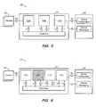
- FIG. 5 illustrates this approach for a typical deployment scenario in which device adapter 512A, data processor 512B and network module 512C build the processing chain of connector 510.
- arrows pointing from a component to the event bus indicate the flow of published messages, and the opposite direction indicates the message flow of subscribed message types.
- data processor 512B publishes messages of type Y and subscribes messages of type X and Z.
- the new version of the component is started at S430. Notably, the new version is started before the old version instance is stopped. Because the new version instance subscribes to messages of the same type as the old version instance, messages will not get lost when the old instance is stopped. Instead, the new version instance takes over the receiving and processing of the subscribed-to messages.
- the old version instance is stopped "gracefully" at S440.
- Graceful stoppage indicates that no new incoming messages that would create new jobs are accepted, while already-accepted messages are allowed to be processed completely.
- the old version instance stops requesting or accepting new jobs from other channels.
- device adapter 512A requests data from a connected sensor device 520.
- the old version instance of device adapter 512A stops requesting data from sensor device 520.
- a new version instance of device adapter 512A takes over this task.
- graceful shutdown might last several seconds.
- the old version instance is stopped after all accepted messages and jobs have been processed, and the supported message types of the old component type version are deregistered at S450.
- the old version of the component type is uninstalled at S460.
- FIG. 6 illustrates process 400 according to some embodiments, based on the deployment scenario of FIG. 5 .
- FIG. 6 illustrates a dynamic software update of data processor 512B.
- the new version of data processor 512B' is loaded and started on connector 510 (e.g., at S410), it subscribes to the same message types X and Z as original data processor 512B (e.g., at S420).
- original data processor 512B starts to a graceful shutdown and stops receiving new jobs by unsubscribing to messages of type X.
- Original data processor 512B does not unsubscribe to those message types that are needed to complete the graceful shutdown.
- Original data processor 512B is able to publish messages of type Y until all of its existing jobs have completed. Next, original data processor 512B is removed, leaving future jobs to be processed by updated data processor 512B'.
- Process 400 advantageously ensures that no messages are dropped, and that the internal processing queue of a component is not lost during an update.
- each component uses a dedicated protected storage to persist temporal data. This ensures the data integrity of the persistent storage for each component instance. Also, components may exchange information only by sending messages to each other over the event bus. The component developer may avoid using shared memory to exchange information because this type of exchange would require a synchronization of concurrent memory accesses.
- an additional attribute of the manifest file of each component type should contain a Boolean value specifying whether the corresponding components technically support the dynamic software update. For example: x-Bundle-SupportsDynamicSoftwareUpdate: ⁇ Boolean>
- the above-mentioned manifest attribute is mapped to the attribute isDynamicUpdateSupported of the component's class instance by using the class constructor. This attribute can be read by calling the appropriate getter method.
- the new version of the component begins subscribing to incoming jobs shortly before the old version of the component unsubscribes from them. Since these two actions cannot be implemented atomically, both the old version and the new version may occasionally receive the same jobs. This may cause a duplication of job processing and therefore double the resource consumption on the connector's hardware device.
- the duplicate jobs may also cause data inconsistencies, for example, to cause an actuator device to perform a mechanical action twice.
- Some embodiments of process 400 may be unable to transfer a state between the old version of a component and the new version of the component. While some components, such as device adapters or network modules, might not have an internal state besides their current processing queue, and can therefore be regarded as stateless, other components, such as data processors, may maintain certain state information. For example, a data processor might aggregate data over multiple incoming messages and therefore requires access to historical data. In the event of an update, the new instance should take over this data from the original instance in order to continue processing.
- FIG. 8 is a sequence diagram illustrating an implementation of process 400 including such handover mechanisms according to some embodiments.
- a connector requests the new component type version from the core repository and initiates the local update procedure updateComponentType().
- This procedure creates and activates the component A' of the new component type version.
- the activation induces the new component to subscribe to incoming messages and, if applicable, to start requesting input from other communication channels.
- the parameter false requests the component to buffer the jobs instead of processing them directly.
- the connector then sends a command to the old version of the component to perform a graceful shutdown.
- the graceful shutdown process immediately deregisters the component from the event bus and the method stopRequestingInput() causes the component to stop requesting new jobs from other communication channels. From this moment on, the old version of the component only handles jobs which it has already received. Once these jobs are complete, the old version of the component sends a handover message to the new version of the component including information on the completed jobs and, optionally, further state information needed by the new component to take over the processing. The new component then applies the state information, removes the completed jobs from its buffer and continues processing. The old version of the component also notifies the connector that it has finished processing, and, in response, the connector deactivates and removes the old component.
- the handover message may contain serialized state information, for example, a list of values representing the state.
- it may contain information on the jobs completed by the old component version. In the general case, this may be a list of identifiers of the completed jobs. If the old component version and the new component version receive jobs in the same order, it is sufficient to only send the identifier of the latest job completed by the old component version.
- the connector or the preprocessing procedure of the core checks the compatibility of the two component versions with respect to their handover message formats before initiating the above-described update process.
- FIG. 9 illustrates a state diagram of components according to some embodiments. Internally, the new state is represented by the attribute isPerformingGraceful-Shutdown.
- the methods updateSubscriptions() and stopRequestingInput() are called to unsubscribe new messages from the event bus and to stop requesting new jobs from other communication channels, if they exist.
- a task of particular relevance is to identify the point in time when all jobs have been processed.
- the component type calls the method checkFinishedAndNotify() every time a job finishes. This method, in turn, checks whether the component is in the state GRACEFUL SHUTDOWN. If so, it calls the method isFinished(), which checks whether all jobs have been processed.
- the subroutine is responsible to publish the handover message by calling sendHandover(S, J) and to notify the connector that the graceful shutdown is finished.
- the method handleHandover(S, J) calls the subroutines applyState(S), remove-Jobs(J) and startProcessing() to take over the state, drop already-processed jobs and continue the processing.
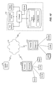
- FIG. 10 is a block diagram of hardware system 1000 according to some embodiments.
- System 1000 includes connector devices 1010A and 1010B, core device 1030 and operator device 1040.
- Each of connector devices 1010A and 1010B includes a processor to execute program code to provide a connector as described above.
- Devices 1010A and 1010B also include software components to execute in their respective containers and to be updated as described herein.
- Devices 1010A and 1010B are connected to respective sensors and actuators according to some embodiments.
- Operator device 1040 may provide user interfaces of a workbench for initiating component updates as described herein.
- operator device 1040 may communicate via World Wide Web 1050 to core device 1030 to request an update of one or more software components.
- Core device 1030 may comprise a computer server including a processor which executes program code of a device configuration service to process an update request as described above with respect to FIG. 2 .
- All systems and processes discussed herein may be embodied in program code stored on one or more computer-readable non-transitory media.
- Such media non-transitory media may include, for example, a fixed disk, a floppy disk, a CD-ROM, a DVD-ROM, a Flash drive, magnetic tape, and solid state RAM or ROM storage units. Embodiments are therefore not limited to any specific combination of hardware and software.
Landscapes
- Engineering & Computer Science (AREA)
- Software Systems (AREA)
- General Engineering & Computer Science (AREA)
- Theoretical Computer Science (AREA)
- Physics & Mathematics (AREA)
- General Physics & Mathematics (AREA)
- Computer Security & Cryptography (AREA)
- Computer Networks & Wireless Communication (AREA)
- Signal Processing (AREA)
- Stored Programmes (AREA)
Abstract
Description
- The cost and the size of basic processing devices have decreased dramatically in recent years. Consequently, the use of processing devices is envisioned in scenarios which would have previously been cost- or space-prohibitive. In one such scenario, many devices are deployed in different places and operational areas, for example in a collection of processing plants. The primary task of these devices may be to measure sensor values, process and persist the data, as well as to forward the data to a backend system. The backend system consolidates the data received from all devices and provides an interface through which the collected data may be consumed by various applications.
- Even if the exact task of a device is fixed upon deployment, it may eventually be desirable to update the software running on the device. For example, updates may be desired to fix detected software bugs, optimize performance of the software and/or the device, or add new features to the software. Depending on the usage scenario, it may be necessary to update the software of thousand of devices simultaneously. Manual intervention is often not feasible due to the sheer number of deployed devices, having different configurations, as well as the geographical distribution of the devices.
-
-
FIG. 1 is a block diagram of a software architecture according to some embodiments. -
FIG. 2 is a flow diagram according to some embodiments. -
FIG. 3 illustrates transformation of a configuration according to some embodiments. -
FIG. 4 is a flow diagram according to some embodiments. -
FIG. 5 is a block diagram of a software architecture according to some embodiments. -
FIG. 6 is a block diagram of a software architecture illustrating updating of a component according to some embodiments. -
FIG. 7 is a class diagram according to some embodiments. -
FIG. 8 is a sequence diagram of a component update according to some embodiments. -
FIG. 9 is a state diagram of a software component according to some embodiments. -
FIG. 10 is a block diagram of a hardware system according to some embodiments. - The following description is provided to enable any person in the art to make and use the described embodiments. Various modifications, however, will remain readily apparent to those in the art.
-
FIG. 1 is a block diagram ofsystem 100 according to some embodiments.System 100 includesconnectors 110,devices 120,core 130,workbench 140,database 150 andapplications 160. As will be described below, some embodiments ofsystem 100 provide an efficient mechanism to automatically update software components of numerous and highly-distributed devices. - Each of
connectors 110,core 130, andworkbench 140 consists of processor-executable program code and/or data. The code and data are stored in memory and executed by a processor of a respective hardware device. For example, each ofconnectors 110 may comprise program code executed by a processor of a respective hardware device,core 130 may consist of program code providing the functions illustrated therein, which is executed by a hardware server. - Each
connector 110 is in communication with and manages one ormore devices 120. Adevice 120 may comprise a sensor, an actuator, a programmable logic controller, or other type of device. Aconnector 110 receives data from and/or transmits data to its one or morecorresponding devices 120. Accordingly, aconnector 110 is typically in proximity of itscorresponding devices 120. - Each
connector 110 also establishes connections tocore 130. Aconnector 110 uses these connections for receiving its device configuration as well as sending processed data tocore 120. - Each
connector 110 is a software container onto whichsoftware components 112A-112C can be deployed. In some embodiments, components may comprise device adapters, data processors and network modules. The container may comprise an Open Service Gateway initiative (OSGi) container, in which case each deployed component may comprise an OSGi component implemented in, for example, Java. Embodiments are not limited to the foregoing protocol or language. - The OSGi framework provides a general-purpose, secure and managed container for Java applications that enables the deployment of extensible software components. In the context of OSGi, these components are known as bundles. Bundles are self-contained applications that can be downloaded and installed within an OSGi container. If a bundle is no longer required, it can be removed from the container. Lifecycle events, such as installing, starting, stopping and uninstalling, can be executed while a bundle is executing.
- A bundle may be packaged and deployed as a Java archive (JAR) file and provides functionality to the application. Besides a collection of class files for the Java programming language, a bundle may also contain other resources such as Extensible Markup Language (XML) files or graphics as well as a bundle documentation. Furthermore, each bundle contains an extensible manifest file. The manifest file describes the content of the JAR file and consists of several key-value pairs, called Manifest Headers. A Manifest Header specifies a bundle's attributes and its dependencies. When the bundle is loaded, the OSGi framework first inspects this manifest file and proceeds loading and running if the stated requirements on other resources are fulfilled.
- The manifest file below states the manifest version which the following specified headers are based on. In addition to a readable name and description of the bundle, the manifest declares a symbolic name and version. The latter two attributes are used to make the bundle identifiable. The Bundle-Activator header sets the name of the Java class which is called to start and stop the bundle. In addition, the manifest file can also list specific execution environments or other dependent bundles required to run the bundle. The Export-Package header declares which packages of the bundle will be made available to other bundles. Likewise, the Import-Package header declares which packages to retrieve from other bundles.
Bundle-ManifestVersion: 2
Bundle-Name: Sample Bundle
Bundle-Description: This is a sample bundle.
Bundle-SymbolicName: com.example.samplebundle
Bundle-Version: 1.0.0
Bundle-Activator: com.example.Activator
Bundle-RequiredExecutionEnvironment: JavaSE-1.6
Require-Bundle: com.example.requiredbundle; bundle-version = "1.1.0"
Export-Package: com.example.samplebundle; version = "1.0.0"
Import-Package: org.osgi.service.io; version = "1.4"
x-customHeader: true - Device adapters manage data communication to and from
devices 120. Data processors manipulate inbound and outbound data by performing operations such as filtering, transforming, aggregating and packaging. Data processors may also be responsible for data persistency, since data may not be transferred tocore 130 immediately. Network modules manage the data communication between aconnector 110 andcore 130 by providing various implementations of network protocols such as WebSocket or Message Queue Telemetry Transport. In addition to the container, aconnector 110 may also provide functions for device onboarding and availability monitoring. -
Core 130 provides an onboarding service for admission of newly-deployed devices, a device control service, a device configuration service and a device messaging service. Each of these services may be implemented in a server-compatible language such as Javascript.Core 130 may be implemented in a local database system and/or in the cloud. -
Core 130 executes the device control service to issue commands to aconnector 110. The device configuration service enables modeling of the device landscape and transmission of configuration parameters. The messaging service is responsible for handling voluminous upstream data payload fromconnectors 110. This upstream data may be persisted and written intodatabase 150. From the persistence, the data can be consumed byvarious applications 160 in order to be analyzed, processed or visualized. -
Core 130 also includes a software repository of packages which may be retrieved and installed onconnectors 110. The software packages may comprise different versions of the connector framework itself as well as many components and versions thereof to run within aconnector 110. -
Database 150 may implement an "in-memory" database, in which volatile (e.g., non-disk-based) storage (e.g., Random Access Memory) is used both for cache memory and for storing the full database during operation, and persistent storage (e.g., one or more fixed disks) is used for offline persistency and maintenance of database snapshots. Alternatively, volatile storage may be used as cache memory for storing recently-used data, while persistent storage stores the full database. In some embodiments, data ofdatabase 150 comprises one or more of conventional tabular data, row-based data stored in row format, column-based data stored in columnar format, and object-based data. -
Workbench 140 may comprise a web application running on top ofcore 130.Workbench 140 provides a user interface that allows an extensive management of deployed devices. Particularly, the web application enables an administrator to enrollnew connectors 110 as well as to define configurations for them and their respective components. In addition,workbench 140 allows an administrator to start, stop, reset and monitor the states ofconnectors 110 and their components. - Returning to components such as
components 112A-1112C, each component may be packaged in a JAR file containing at least a valid manifest file as well as an activator class which implements a start and a stop method. Furthermore, the framework ofconnector 110 expects a component's JAR file to contain three interface specifications that are used to integrate a component intosystem 100. These three interface specifications are: 1) a definition of the component's configuration parameters; 2) a list of message types the component is able to consume and produce; and 3) a user interface (UI) which enables an administrator to configure the component's parameters. - The definition of a component's configuration parameters is realized by an Extensible Markup Language Schema Definition (XSD) file. The XSD file formally describes and constrains the contents of XML documents. As will be described below, each well-formed XML document that is validated against a component's schema definition can be used as a configuration for the component. Via a marshalling method, the configuration XML document is transformed into an internal Java object representation such that the configuration parameters can be used at runtime.
- Components share information by sending messages to each other. The list of message types defines the interface used by the components for these messages. According to some embodiments, the communication utilizes the service layer of the OSGi framework. When a component is loaded, a routine registers a service with the service registry of the service layer that subscribes for messages of the specified message types. Each message type indicates its structure and data types.
- The aforementioned UI specification is delivered with the component type's JAR file and is integrated into
workbench 140 when a corresponding component needs to be configured. The UI specification may be based on a UI framework for developing rich user interfaces for web applications. The UI of a component type's JAR file may consist of a model (i.e., a configuration XML document validated against a configuration XSD), a controller (i.e., code to manipulate the XML document), and a view (i.e., code to generate an output representation from the XML document). -
FIG. 2 comprises a flow diagram ofprocess 200 according to some embodiments.Process 200 may be executed in some embodiments to enable a remote update of components running on top of distributed connectors. In some embodiments, a processor ofcore 130 executes its device configuration service to performprocess 200. -
Process 200 and all other processes mentioned herein may be embodied in processor-executable program code read from one or more of non-transitory computer-readable media, such as a floppy disk, a CD-ROM, a DVD-ROM, a Flash drive, and a magnetic tape, and then stored in a compressed, uncompiled and/or encrypted format. In some embodiments, hard-wired circuitry may be used in place of, or in combination with, program code for implementation of processes according to some embodiments. Embodiments are therefore not limited to any specific combination of hardware and software. - Prior to process 400, it is assumed that new component type versions (e.g., JAR files) have already been uploaded to the repository of the
core 130. To trigger a component update, an administrator operatesworkbench 140 to filter a subset of the managed devices and specify the execution time of the update. Depending on the reason for the update, the deployment scenario and the size of the infrastructure, an update might only be applied to a single component 112 running on oneconnector 110 or to a more specific selection of devices. For example,workbench 140 may allow an administrator to trigger an update for components 112 of allconnectors 110 that are located in a specific area. To allow such filters,workbench 140 is aware of the current deployment state of its managed devices. - According to some embodiments, an update request may include any of the optional filters Organizations, Locations, Connectors, Components and OriginalComponentTypeVersion. Values for each of these filters may be specified using identifiers of the corresponding entities. Mandatory filters of the update request may include ComponentType and TargetComponentTypeVersion. ComponentType specifies an identifier of a component type to which the selected components will be updated, and TargetComponentTypeVersion is used to specify a component type version to which the selected components will be updated.
- A corresponding serialized format of an update request using the above attributes is as follows:
        [{
               Connector: [10]
               OriginalComponentTypeVersion: [2, 3]
               ComponentType: 1,
               TargetComponentTypeVersion: 4
        }]
        [{
               Organizations: [1, 2],
               ComponentType: null,
               TargetComponentTypeVersion: null
        },
               Organizations: [3],
               Location: [1],
               ComponentType: 2,
               TargetComponentTypeVersion: 5
       }]
 <?xml version="1.0" encoding="UTF-8" ?>
 <xs:schema xmlns:xs="http://www.w3.org/2001/XMLSchema">
     <xs:element name=" SampleConfiguration ">
         <xs:complexType>
              <xs:all>
                  <xs:element name="param0" type="xs:integer"/>
              </xs:all>
         </xs:complexType>
     </xs:element>
 </xs:schema>
 <?xml version="1.0" encoding="UTF-8"?>
 <SampleConfiguration>
        <param0>2</param0>
 </SampleConfiguration>
- <xs:schema xmlns:xs="http://www.w3.org/2001/XMLSchema" version="MAJOR.MINOR.PATCH">
- x-Bundle-Configuration-Version: <MAJOR.MINOR.PATCH>
| Attribute | Description |
| ID | Identifier of the component to be updated |
| SYMBOLIC_NAME | Identifier of the targeted component type |
| VERSION | Identifier of the targeted component type version |
| CONFIGURATION | XML Configuration for the updated IoT Component if it has changed, empty otherwise |
| REMOVED_MESSAGE_TYPES | List of removed message types |
| ADDED_MESSAGE_TYPES | List of added message types |
| REMOVED_SUPPORTED_MESSAGE_TYPES | List of removed supported message types |
| ADDED_SUPPORTED_MESSAGE_TYPES | List of added supported message types |
| EXECUTION_TIME | Point in time when to perform the update if desired, empty otherwise |
Claims (15)
- A system comprising:a processor; anda memory storing processor-executable process steps executable by the processor to cause the system to:execute a first version of a software component type within a software container;during execution of the first version of the software component type, install a second version of the software component type in the software container;during execution of the first version of the software component type, register supported message types of the second version of the software component type;during execution of the first version of the software component type, execute the second version of the software component type in the software container; andexecute the first version of the software component type to stop accepting incoming messages, to complete processing of jobs associated with already-accepted messages, and to transmit a handover message to the second version of the software component type comprising information associated with the completed jobs.
- A system according to Claim 1, wherein the process steps are further executable by the processor to cause the system to:execute the second version of the software component type to receive the handover message and to remove the completed jobs from a buffer associated with the second version of the software component type.
- A system according to Claim 1 or 2, wherein the handover message further comprises state information of the first version of the software component type.
- A system according to Claim 3, wherein the process steps are further executable by the processor to cause the system to:execute the second version of the software component type to receive the handover message, to update a state of the second version of the software component type based on the state information, and to remove the completed jobs from a buffer associated with the second version of the software component type.
- A system according to any one of Claims 1-4, the process steps further executable by the processor to cause the system to:after transmission of the handover message, deregister supported message types of the first version of the software component type and un-install the second version of the software component type from the software container.
- A system according to any one of Claims 1-5, the process steps further executable by the processor to cause the system to:execute a first version of a second software component type within the software container;during execution of the first version of the second software component type, install a second version of the second software component type in the software container;during execution of the first version of the second software component type, register supported message types of the second version of the second software component type;during execution of the first version of the second software component type, execute the second version of the second software component type in the software container; andexecute the first version of the second software component type to stop accepting incoming messages, to complete processing of second jobs associated with messages already-accepted by the first version of the second software component type, and to transmit a second handover message to the second version of the second software component type comprising information associated with the second completed jobs.
- A system according to Claim 6, wherein the second handover message further comprises second state information of the first version of the second software component type, and wherein the process steps are further executable by the processor to cause the system to:execute the second version of the second software component type to receive the second handover message, to update a second state of the second version of the software component type based on the second state information, and to remove the second completed jobs from a buffer associated with the second version of the second software component type.
- A method implemented by a computing system in response to execution of program code by a processor of the computing system, the method comprising:executing a first version of a software component type within a software container;during execution of the first version of the software component type, installing a second version of the software component type in the software container;during execution of the first version of the software component type, registering supported message types of the second version of the software component type;during execution of the first version of the software component type, executing the second version of the software component type in the software container; andexecuting the first version of the software component type to stop accepting incoming messages, to complete processing of jobs associated with already-accepted messages, and to transmit a handover message to the second version of the software component type comprising information associated with the completed jobs.
- A method according to Claim 8, further comprising
executing the second version of the software component type to receive the handover message and to remove the completed jobs from a buffer associated with the second version of the software component type. - A method according to Claim 8 or 9, wherein the handover message further comprises state information of the first version of the software component type.
- A method according to Claim 10, further comprising:executing the second version of the software component type to receive the handover message, to update a state of the second version of the software component type based on the state information, and to remove the completed jobs from a buffer associated with the second version of the software component type.
- A method according to any one of Claims 8-11, further comprising:after transmission of the handover message, deregistering supported message types of the first version of the software component type and un-installing the second version of the software component type from the software container.
- A method according to any one of Claims 8-12, further comprising:executing a first version of a second software component type within the software container;during execution of the first version of the second software component type, installing a second version of the second software component type in the software container;during execution of the first version of the second software component type, registering supported message types of the second version of the second software component type;during execution of the first version of the second software component type, executing the second version of the second software component type in the software container; andexecuting the first version of the second software component type to stop accepting incoming messages, to complete processing of second jobs associated with messages already-accepted by the first version of the second software component type, and to transmit a second handover message to the second version of the second software component type comprising information associated with the second completed jobs.
- A method according to Claim 13, wherein the second handover message further comprises second state information of the first version of the second software component type, and further comprising:executing the second version of the second software component type to receive the second handover message, to update a second state of the second version of the software component type based on the second state information, and to remove the second completed jobs from a buffer associated with the second version of the second software component type.
- A non-transitory computer-readable medium storing program code, the program code executable by a processor of a computing system to cause the computing system to perform a method according to any one of claims 8-14.
Applications Claiming Priority (1)
| Application Number | Priority Date | Filing Date | Title |
|---|---|---|---|
| US14/561,903 US20160162277A1 (en) | 2014-12-05 | 2014-12-05 | Remote update of software components |
Publications (2)
| Publication Number | Publication Date |
|---|---|
| EP3029568A1 true EP3029568A1 (en) | 2016-06-08 |
| EP3029568B1 EP3029568B1 (en) | 2022-01-05 |
Family
ID=54365931
Family Applications (1)
| Application Number | Title | Priority Date | Filing Date |
|---|---|---|---|
| EP15003140.9A Active EP3029568B1 (en) | 2014-12-05 | 2015-11-03 | Remote update of software components |
Country Status (2)
| Country | Link |
|---|---|
| US (1) | US20160162277A1 (en) |
| EP (1) | EP3029568B1 (en) |
Cited By (2)
| Publication number | Priority date | Publication date | Assignee | Title |
|---|---|---|---|---|
| CN109710275A (en) * | 2018-12-19 | 2019-05-03 | 中科曙光国际信息产业有限公司 | A kind of the software uninstalling system and method for distributed type assemblies |
| WO2022156056A1 (en) * | 2021-01-19 | 2022-07-28 | 南京大学 | Program source code reslicing-based software dynamic update hot patch synthesis method |
Families Citing this family (12)
| Publication number | Priority date | Publication date | Assignee | Title |
|---|---|---|---|---|
| US9652220B2 (en) * | 2015-05-11 | 2017-05-16 | Sap Portals Israel Ltd. | Zero down-time deployment of new application versions |
| DE102018204188A1 (en) * | 2018-03-20 | 2019-09-26 | Audi Ag | A method for updating a software application in a device that is in operation, and device and motor vehicle |
| CN109343860A (en) * | 2018-08-23 | 2019-02-15 | 腾讯科技(深圳)有限公司 | A method, device, server and medium for cleaning game patches |
| US10956139B2 (en) * | 2018-11-26 | 2021-03-23 | Sap Se | Integration process to integration adapter connector |
| US11288053B2 (en) | 2019-08-15 | 2022-03-29 | Microstrategy Incorporated | Conversion and restoration of computer environments to container-based implementations |
| US11829742B2 (en) * | 2019-08-15 | 2023-11-28 | Microstrategy Incorporated | Container-based server environments |
| US11106455B2 (en) | 2019-08-15 | 2021-08-31 | Microstrategy Incorporated | Integration of containers with external elements |
| US11128736B2 (en) | 2019-09-09 | 2021-09-21 | Google Llc | Dynamically configurable client application activity |
| US11836158B2 (en) | 2020-02-03 | 2023-12-05 | Microstrategy Incorporated | Deployment of container-based computer environments |
| EP3968150A1 (en) * | 2020-09-09 | 2022-03-16 | Siemens Aktiengesellschaft | Embedded control device, computer program product and method of controlling a control target |
| US11954473B2 (en) | 2021-09-20 | 2024-04-09 | Microstrategy Incorporated | Deployment architecture for multi-tenant cloud computing systems |
| US11861342B2 (en) | 2022-01-28 | 2024-01-02 | Microstrategy Incorporated | Enhanced cloud-computing environment deployment |
Citations (2)
| Publication number | Priority date | Publication date | Assignee | Title |
|---|---|---|---|---|
| US6385770B1 (en) * | 1999-01-29 | 2002-05-07 | Telefonaktiebolaget Lm Ericsson (Publ) | Software upgrade |
| US20130277969A1 (en) * | 2012-04-20 | 2013-10-24 | Kaj Skov Nielsen | Wind park control system |
Family Cites Families (2)
| Publication number | Priority date | Publication date | Assignee | Title |
|---|---|---|---|---|
| US8140687B2 (en) * | 2008-11-13 | 2012-03-20 | Hughes Network Systems, Llc | Performance enhancing proxy handover |
| US8863111B2 (en) * | 2009-06-26 | 2014-10-14 | Oracle International Corporation | System and method for providing a production upgrade of components within a multiprotocol gateway |
-
2014
- 2014-12-05 US US14/561,903 patent/US20160162277A1/en not_active Abandoned
-
2015
- 2015-11-03 EP EP15003140.9A patent/EP3029568B1/en active Active
Patent Citations (2)
| Publication number | Priority date | Publication date | Assignee | Title |
|---|---|---|---|---|
| US6385770B1 (en) * | 1999-01-29 | 2002-05-07 | Telefonaktiebolaget Lm Ericsson (Publ) | Software upgrade |
| US20130277969A1 (en) * | 2012-04-20 | 2013-10-24 | Kaj Skov Nielsen | Wind park control system |
Cited By (3)
| Publication number | Priority date | Publication date | Assignee | Title |
|---|---|---|---|---|
| CN109710275A (en) * | 2018-12-19 | 2019-05-03 | 中科曙光国际信息产业有限公司 | A kind of the software uninstalling system and method for distributed type assemblies |
| CN109710275B (en) * | 2018-12-19 | 2022-01-28 | 中科曙光国际信息产业有限公司 | Software unloading system and method for distributed cluster |
| WO2022156056A1 (en) * | 2021-01-19 | 2022-07-28 | 南京大学 | Program source code reslicing-based software dynamic update hot patch synthesis method |
Also Published As
| Publication number | Publication date |
|---|---|
| EP3029568B1 (en) | 2022-01-05 |
| US20160162277A1 (en) | 2016-06-09 |
Similar Documents
| Publication | Publication Date | Title |
|---|---|---|
| EP3029568B1 (en) | Remote update of software components | |
| US11373127B2 (en) | Connection multiplexing for a parallel processing environment | |
| US8762929B2 (en) | System and method for exclusion of inconsistent objects from lifecycle management processes | |
| US8689179B2 (en) | Transportable refactoring object | |
| CN100407154C (en) | Systems and methods for modeling and dynamically deploying services in a distributed network architecture | |
| US9253265B2 (en) | Hot pluggable extensions for access management system | |
| US8533230B2 (en) | Expressing manageable resource topology graphs as dynamic stateful resources | |
| EP1934822A2 (en) | Interfaces for a productivity suite application and a hosted user interface | |
| KR20120098859A (en) | Lock resolution for distributed durable instances | |
| CN113179269A (en) | Internet of things-based protocol data analysis method, system, medium, and program product | |
| WO2025200526A1 (en) | Cache processing method and apparatus, storage medium and electronic device | |
| US20150295984A1 (en) | Multi Web Application Management Framework System and Method | |
| US7778965B2 (en) | Systems and methods for common instance handling of providers in a plurality of frameworks | |
| US20070124740A1 (en) | Systems and methods for adapting procedure calls to service providers | |
| US9665416B1 (en) | Asynchronous execution of computer operations | |
| US10152490B2 (en) | Sequential replication with limited number of objects | |
| US20070174697A1 (en) | Generic, WSRF-compliant checkpointing for WS-Resources | |
| CN115373886A (en) | Service group container shutdown method, device, computer equipment and storage medium | |
| CN108920683A (en) | A method, device and storage medium for downloading external resources on a cloud computing platform | |
| US20170052803A1 (en) | Dynamically provisioning, managing, and executing tasks | |
| CN115016800A (en) | Software development automation processing method and device for continuous integrated deployment | |
| EP2746938A1 (en) | System and method for activating a software module | |
| Ribeiro | Safe Api Evolution in a Microservice Architecture with a Pluggable and Transactionless Solution | |
| Anandan et al. | Spring Cloud Stream Reference Guide | |
| CN118466991A (en) | Node management component upgrading method and device, electronic equipment and storage medium |
Legal Events
| Date | Code | Title | Description |
|---|---|---|---|
| PUAI | Public reference made under article 153(3) epc to a published international application that has entered the european phase |
Free format text: ORIGINAL CODE: 0009012 |
|
| AK | Designated contracting states |
Kind code of ref document: A1 Designated state(s): AL AT BE BG CH CY CZ DE DK EE ES FI FR GB GR HR HU IE IS IT LI LT LU LV MC MK MT NL NO PL PT RO RS SE SI SK SM TR |
|
| AX | Request for extension of the european patent |
Extension state: BA ME |
|
| STAA | Information on the status of an ep patent application or granted ep patent |
Free format text: STATUS: REQUEST FOR EXAMINATION WAS MADE |
|
| 17P | Request for examination filed |
Effective date: 20161207 |
|
| RBV | Designated contracting states (corrected) |
Designated state(s): AL AT BE BG CH CY CZ DE DK EE ES FI FR GB GR HR HU IE IS IT LI LT LU LV MC MK MT NL NO PL PT RO RS SE SI SK SM TR |
|
| STAA | Information on the status of an ep patent application or granted ep patent |
Free format text: STATUS: EXAMINATION IS IN PROGRESS |
|
| 17Q | First examination report despatched |
Effective date: 20190206 |
|
| REG | Reference to a national code |
Ref country code: DE Ref legal event code: R079 Ref document number: 602015076179 Country of ref document: DE Free format text: PREVIOUS MAIN CLASS: G06F0009445000 Ipc: G06F0008656000 |
|
| RIC1 | Information provided on ipc code assigned before grant |
Ipc: G06F 8/656 20180101AFI20210429BHEP |
|
| GRAP | Despatch of communication of intention to grant a patent |
Free format text: ORIGINAL CODE: EPIDOSNIGR1 |
|
| STAA | Information on the status of an ep patent application or granted ep patent |
Free format text: STATUS: GRANT OF PATENT IS INTENDED |
|
| INTG | Intention to grant announced |
Effective date: 20210618 |
|
| GRAS | Grant fee paid |
Free format text: ORIGINAL CODE: EPIDOSNIGR3 |
|
| GRAA | (expected) grant |
Free format text: ORIGINAL CODE: 0009210 |
|
| STAA | Information on the status of an ep patent application or granted ep patent |
Free format text: STATUS: THE PATENT HAS BEEN GRANTED |
|
| AK | Designated contracting states |
Kind code of ref document: B1 Designated state(s): AL AT BE BG CH CY CZ DE DK EE ES FI FR GB GR HR HU IE IS IT LI LT LU LV MC MK MT NL NO PL PT RO RS SE SI SK SM TR |
|
| REG | Reference to a national code |
Ref country code: GB Ref legal event code: FG4D |
|
| REG | Reference to a national code |
Ref country code: CH Ref legal event code: EP |
|
| REG | Reference to a national code |
Ref country code: AT Ref legal event code: REF Ref document number: 1461177 Country of ref document: AT Kind code of ref document: T Effective date: 20220115 |
|
| REG | Reference to a national code |
Ref country code: DE Ref legal event code: R096 Ref document number: 602015076179 Country of ref document: DE |
|
| REG | Reference to a national code |
Ref country code: IE Ref legal event code: FG4D |
|
| REG | Reference to a national code |
Ref country code: LT Ref legal event code: MG9D |
|
| REG | Reference to a national code |
Ref country code: NL Ref legal event code: MP Effective date: 20220105 |
|
| REG | Reference to a national code |
Ref country code: AT Ref legal event code: MK05 Ref document number: 1461177 Country of ref document: AT Kind code of ref document: T Effective date: 20220105 |
|
| PG25 | Lapsed in a contracting state [announced via postgrant information from national office to epo] |
Ref country code: NL Free format text: LAPSE BECAUSE OF FAILURE TO SUBMIT A TRANSLATION OF THE DESCRIPTION OR TO PAY THE FEE WITHIN THE PRESCRIBED TIME-LIMIT Effective date: 20220105 |
|
| PG25 | Lapsed in a contracting state [announced via postgrant information from national office to epo] |
Ref country code: SE Free format text: LAPSE BECAUSE OF FAILURE TO SUBMIT A TRANSLATION OF THE DESCRIPTION OR TO PAY THE FEE WITHIN THE PRESCRIBED TIME-LIMIT Effective date: 20220105 Ref country code: RS Free format text: LAPSE BECAUSE OF FAILURE TO SUBMIT A TRANSLATION OF THE DESCRIPTION OR TO PAY THE FEE WITHIN THE PRESCRIBED TIME-LIMIT Effective date: 20220105 Ref country code: PT Free format text: LAPSE BECAUSE OF FAILURE TO SUBMIT A TRANSLATION OF THE DESCRIPTION OR TO PAY THE FEE WITHIN THE PRESCRIBED TIME-LIMIT Effective date: 20220505 Ref country code: NO Free format text: LAPSE BECAUSE OF FAILURE TO SUBMIT A TRANSLATION OF THE DESCRIPTION OR TO PAY THE FEE WITHIN THE PRESCRIBED TIME-LIMIT Effective date: 20220405 Ref country code: LT Free format text: LAPSE BECAUSE OF FAILURE TO SUBMIT A TRANSLATION OF THE DESCRIPTION OR TO PAY THE FEE WITHIN THE PRESCRIBED TIME-LIMIT Effective date: 20220105 Ref country code: HR Free format text: LAPSE BECAUSE OF FAILURE TO SUBMIT A TRANSLATION OF THE DESCRIPTION OR TO PAY THE FEE WITHIN THE PRESCRIBED TIME-LIMIT Effective date: 20220105 Ref country code: ES Free format text: LAPSE BECAUSE OF FAILURE TO SUBMIT A TRANSLATION OF THE DESCRIPTION OR TO PAY THE FEE WITHIN THE PRESCRIBED TIME-LIMIT Effective date: 20220105 Ref country code: BG Free format text: LAPSE BECAUSE OF FAILURE TO SUBMIT A TRANSLATION OF THE DESCRIPTION OR TO PAY THE FEE WITHIN THE PRESCRIBED TIME-LIMIT Effective date: 20220405 |
|
| PG25 | Lapsed in a contracting state [announced via postgrant information from national office to epo] |
Ref country code: PL Free format text: LAPSE BECAUSE OF FAILURE TO SUBMIT A TRANSLATION OF THE DESCRIPTION OR TO PAY THE FEE WITHIN THE PRESCRIBED TIME-LIMIT Effective date: 20220105 Ref country code: LV Free format text: LAPSE BECAUSE OF FAILURE TO SUBMIT A TRANSLATION OF THE DESCRIPTION OR TO PAY THE FEE WITHIN THE PRESCRIBED TIME-LIMIT Effective date: 20220105 Ref country code: GR Free format text: LAPSE BECAUSE OF FAILURE TO SUBMIT A TRANSLATION OF THE DESCRIPTION OR TO PAY THE FEE WITHIN THE PRESCRIBED TIME-LIMIT Effective date: 20220406 Ref country code: FI Free format text: LAPSE BECAUSE OF FAILURE TO SUBMIT A TRANSLATION OF THE DESCRIPTION OR TO PAY THE FEE WITHIN THE PRESCRIBED TIME-LIMIT Effective date: 20220105 Ref country code: AT Free format text: LAPSE BECAUSE OF FAILURE TO SUBMIT A TRANSLATION OF THE DESCRIPTION OR TO PAY THE FEE WITHIN THE PRESCRIBED TIME-LIMIT Effective date: 20220105 |
|
| PG25 | Lapsed in a contracting state [announced via postgrant information from national office to epo] |
Ref country code: IS Free format text: LAPSE BECAUSE OF FAILURE TO SUBMIT A TRANSLATION OF THE DESCRIPTION OR TO PAY THE FEE WITHIN THE PRESCRIBED TIME-LIMIT Effective date: 20220505 |
|
| REG | Reference to a national code |
Ref country code: DE Ref legal event code: R097 Ref document number: 602015076179 Country of ref document: DE |
|
| PG25 | Lapsed in a contracting state [announced via postgrant information from national office to epo] |
Ref country code: SM Free format text: LAPSE BECAUSE OF FAILURE TO SUBMIT A TRANSLATION OF THE DESCRIPTION OR TO PAY THE FEE WITHIN THE PRESCRIBED TIME-LIMIT Effective date: 20220105 Ref country code: SK Free format text: LAPSE BECAUSE OF FAILURE TO SUBMIT A TRANSLATION OF THE DESCRIPTION OR TO PAY THE FEE WITHIN THE PRESCRIBED TIME-LIMIT Effective date: 20220105 Ref country code: RO Free format text: LAPSE BECAUSE OF FAILURE TO SUBMIT A TRANSLATION OF THE DESCRIPTION OR TO PAY THE FEE WITHIN THE PRESCRIBED TIME-LIMIT Effective date: 20220105 Ref country code: EE Free format text: LAPSE BECAUSE OF FAILURE TO SUBMIT A TRANSLATION OF THE DESCRIPTION OR TO PAY THE FEE WITHIN THE PRESCRIBED TIME-LIMIT Effective date: 20220105 Ref country code: DK Free format text: LAPSE BECAUSE OF FAILURE TO SUBMIT A TRANSLATION OF THE DESCRIPTION OR TO PAY THE FEE WITHIN THE PRESCRIBED TIME-LIMIT Effective date: 20220105 Ref country code: CZ Free format text: LAPSE BECAUSE OF FAILURE TO SUBMIT A TRANSLATION OF THE DESCRIPTION OR TO PAY THE FEE WITHIN THE PRESCRIBED TIME-LIMIT Effective date: 20220105 |
|
| PLBE | No opposition filed within time limit |
Free format text: ORIGINAL CODE: 0009261 |
|
| STAA | Information on the status of an ep patent application or granted ep patent |
Free format text: STATUS: NO OPPOSITION FILED WITHIN TIME LIMIT |
|
| PG25 | Lapsed in a contracting state [announced via postgrant information from national office to epo] |
Ref country code: AL Free format text: LAPSE BECAUSE OF FAILURE TO SUBMIT A TRANSLATION OF THE DESCRIPTION OR TO PAY THE FEE WITHIN THE PRESCRIBED TIME-LIMIT Effective date: 20220105 |
|
| 26N | No opposition filed |
Effective date: 20221006 |
|
| PG25 | Lapsed in a contracting state [announced via postgrant information from national office to epo] |
Ref country code: SI Free format text: LAPSE BECAUSE OF FAILURE TO SUBMIT A TRANSLATION OF THE DESCRIPTION OR TO PAY THE FEE WITHIN THE PRESCRIBED TIME-LIMIT Effective date: 20220105 |
|
| PG25 | Lapsed in a contracting state [announced via postgrant information from national office to epo] |
Ref country code: MC Free format text: LAPSE BECAUSE OF FAILURE TO SUBMIT A TRANSLATION OF THE DESCRIPTION OR TO PAY THE FEE WITHIN THE PRESCRIBED TIME-LIMIT Effective date: 20220105 |
|
| REG | Reference to a national code |
Ref country code: CH Ref legal event code: PL |
|
| REG | Reference to a national code |
Ref country code: BE Ref legal event code: MM Effective date: 20221130 |
|
| PG25 | Lapsed in a contracting state [announced via postgrant information from national office to epo] |
Ref country code: LI Free format text: LAPSE BECAUSE OF NON-PAYMENT OF DUE FEES Effective date: 20221130 Ref country code: IT Free format text: LAPSE BECAUSE OF FAILURE TO SUBMIT A TRANSLATION OF THE DESCRIPTION OR TO PAY THE FEE WITHIN THE PRESCRIBED TIME-LIMIT Effective date: 20220105 Ref country code: CH Free format text: LAPSE BECAUSE OF NON-PAYMENT OF DUE FEES Effective date: 20221130 |
|
| PG25 | Lapsed in a contracting state [announced via postgrant information from national office to epo] |
Ref country code: LU Free format text: LAPSE BECAUSE OF NON-PAYMENT OF DUE FEES Effective date: 20221103 |
|
| PG25 | Lapsed in a contracting state [announced via postgrant information from national office to epo] |
Ref country code: IE Free format text: LAPSE BECAUSE OF NON-PAYMENT OF DUE FEES Effective date: 20221103 |
|
| PG25 | Lapsed in a contracting state [announced via postgrant information from national office to epo] |
Ref country code: BE Free format text: LAPSE BECAUSE OF NON-PAYMENT OF DUE FEES Effective date: 20221130 |
|
| PG25 | Lapsed in a contracting state [announced via postgrant information from national office to epo] |
Ref country code: HU Free format text: LAPSE BECAUSE OF FAILURE TO SUBMIT A TRANSLATION OF THE DESCRIPTION OR TO PAY THE FEE WITHIN THE PRESCRIBED TIME-LIMIT; INVALID AB INITIO Effective date: 20151103 |
|
| PG25 | Lapsed in a contracting state [announced via postgrant information from national office to epo] |
Ref country code: CY Free format text: LAPSE BECAUSE OF FAILURE TO SUBMIT A TRANSLATION OF THE DESCRIPTION OR TO PAY THE FEE WITHIN THE PRESCRIBED TIME-LIMIT Effective date: 20220105 |
|
| PG25 | Lapsed in a contracting state [announced via postgrant information from national office to epo] |
Ref country code: MK Free format text: LAPSE BECAUSE OF FAILURE TO SUBMIT A TRANSLATION OF THE DESCRIPTION OR TO PAY THE FEE WITHIN THE PRESCRIBED TIME-LIMIT Effective date: 20220105 |
|
| PG25 | Lapsed in a contracting state [announced via postgrant information from national office to epo] |
Ref country code: TR Free format text: LAPSE BECAUSE OF FAILURE TO SUBMIT A TRANSLATION OF THE DESCRIPTION OR TO PAY THE FEE WITHIN THE PRESCRIBED TIME-LIMIT Effective date: 20220105 |
|
| PG25 | Lapsed in a contracting state [announced via postgrant information from national office to epo] |
Ref country code: MT Free format text: LAPSE BECAUSE OF FAILURE TO SUBMIT A TRANSLATION OF THE DESCRIPTION OR TO PAY THE FEE WITHIN THE PRESCRIBED TIME-LIMIT Effective date: 20220105 |
|
| PGFP | Annual fee paid to national office [announced via postgrant information from national office to epo] |
Ref country code: DE Payment date: 20251119 Year of fee payment: 11 |
|
| PGFP | Annual fee paid to national office [announced via postgrant information from national office to epo] |
Ref country code: GB Payment date: 20251121 Year of fee payment: 11 |
|
| PGFP | Annual fee paid to national office [announced via postgrant information from national office to epo] |
Ref country code: FR Payment date: 20251125 Year of fee payment: 11 |