EP3029534A1 - Teaching apparatus used for operation of industrial robot - Google Patents
Teaching apparatus used for operation of industrial robot Download PDFInfo
- Publication number
- EP3029534A1 EP3029534A1 EP15003042.7A EP15003042A EP3029534A1 EP 3029534 A1 EP3029534 A1 EP 3029534A1 EP 15003042 A EP15003042 A EP 15003042A EP 3029534 A1 EP3029534 A1 EP 3029534A1
- Authority
- EP
- European Patent Office
- Prior art keywords
- robot
- teaching apparatus
- manipulating portion
- welding
- face
- Prior art date
- Legal status (The legal status is an assumption and is not a legal conclusion. Google has not performed a legal analysis and makes no representation as to the accuracy of the status listed.)
- Granted
Links
Images


Classifications
-
- B—PERFORMING OPERATIONS; TRANSPORTING
- B25—HAND TOOLS; PORTABLE POWER-DRIVEN TOOLS; MANIPULATORS
- B25J—MANIPULATORS; CHAMBERS PROVIDED WITH MANIPULATION DEVICES
- B25J9/00—Programme-controlled manipulators
- B25J9/16—Programme controls
- B25J9/1656—Programme controls characterised by programming, planning systems for manipulators
-
- B—PERFORMING OPERATIONS; TRANSPORTING
- B25—HAND TOOLS; PORTABLE POWER-DRIVEN TOOLS; MANIPULATORS
- B25J—MANIPULATORS; CHAMBERS PROVIDED WITH MANIPULATION DEVICES
- B25J13/00—Controls for manipulators
- B25J13/06—Control stands, e.g. consoles, switchboards
-
- G—PHYSICS
- G05—CONTROLLING; REGULATING
- G05B—CONTROL OR REGULATING SYSTEMS IN GENERAL; FUNCTIONAL ELEMENTS OF SUCH SYSTEMS; MONITORING OR TESTING ARRANGEMENTS FOR SUCH SYSTEMS OR ELEMENTS
- G05B19/00—Programme-control systems
- G05B19/02—Programme-control systems electric
- G05B19/18—Numerical control [NC], i.e. automatically operating machines, in particular machine tools, e.g. in a manufacturing environment, so as to execute positioning, movement or co-ordinated operations by means of programme data in numerical form
- G05B19/409—Numerical control [NC], i.e. automatically operating machines, in particular machine tools, e.g. in a manufacturing environment, so as to execute positioning, movement or co-ordinated operations by means of programme data in numerical form characterised by using manual input [MDI] or by using control panel, e.g. controlling functions with the panel; characterised by control panel details, by setting parameters
-
- G—PHYSICS
- G05—CONTROLLING; REGULATING
- G05B—CONTROL OR REGULATING SYSTEMS IN GENERAL; FUNCTIONAL ELEMENTS OF SUCH SYSTEMS; MONITORING OR TESTING ARRANGEMENTS FOR SUCH SYSTEMS OR ELEMENTS
- G05B19/00—Programme-control systems
- G05B19/02—Programme-control systems electric
- G05B19/42—Recording and playback systems, i.e. in which the programme is recorded from a cycle of operations, e.g. the cycle of operations being manually controlled, after which this record is played back on the same machine
- G05B19/425—Teaching successive positions by numerical control, i.e. commands being entered to control the positioning servo of the tool head or end effector
-
- G—PHYSICS
- G05—CONTROLLING; REGULATING
- G05B—CONTROL OR REGULATING SYSTEMS IN GENERAL; FUNCTIONAL ELEMENTS OF SUCH SYSTEMS; MONITORING OR TESTING ARRANGEMENTS FOR SUCH SYSTEMS OR ELEMENTS
- G05B2219/00—Program-control systems
- G05B2219/30—Nc systems
- G05B2219/36—Nc in input of data, input key till input tape
- G05B2219/36162—Pendant control box
-
- G—PHYSICS
- G05—CONTROLLING; REGULATING
- G05B—CONTROL OR REGULATING SYSTEMS IN GENERAL; FUNCTIONAL ELEMENTS OF SUCH SYSTEMS; MONITORING OR TESTING ARRANGEMENTS FOR SUCH SYSTEMS OR ELEMENTS
- G05B2219/00—Program-control systems
- G05B2219/30—Nc systems
- G05B2219/39—Robotics, robotics to robotics hand
- G05B2219/39443—Portable, adapted to handpalm, with joystick, function keys, display
-
- Y—GENERAL TAGGING OF NEW TECHNOLOGICAL DEVELOPMENTS; GENERAL TAGGING OF CROSS-SECTIONAL TECHNOLOGIES SPANNING OVER SEVERAL SECTIONS OF THE IPC; TECHNICAL SUBJECTS COVERED BY FORMER USPC CROSS-REFERENCE ART COLLECTIONS [XRACs] AND DIGESTS
- Y10—TECHNICAL SUBJECTS COVERED BY FORMER USPC
- Y10S—TECHNICAL SUBJECTS COVERED BY FORMER USPC CROSS-REFERENCE ART COLLECTIONS [XRACs] AND DIGESTS
- Y10S901/00—Robots
- Y10S901/02—Arm motion controller
- Y10S901/03—Teaching system
- Y10S901/05—Machine driven lead through
Definitions
- the present invention relates to a teaching apparatus used for operation of an industrial robot.
- an operation for checking welding parameters is performed by moving the robot prior to actual welding operation.
- Such a checking operation is performed for optimizing the shape and the penetration of the bead by changing welding parameters, such as welding current, arc voltage, and welding speed, through a teaching apparatus.
- welding parameters such as welding current, arc voltage, and welding speed
- the checking operation the operator needs to check the state of the welded part during the welding operation and therefore performs the checking operation near the arm tip of the robot where arc is generated.
- the checking operation is performed in a manual mode in which the robot is moved manually.
- ISO International Organization of Standardization
- the hold-to-run function is a function that permits the robot to move only when the function is operated manually with a hand of an operator, and stops the robot when the hand is released from the function.
- the operator changes any of the welding parameters while pressing both a switch (an enabling switch) of an enabling device that starts electrification of the robot and a button that permits the robot to move.
- An exemplary known teaching apparatus includes an enabling switch provided on the back face thereof and other operation buttons provided on the front face thereof.
- a one-handed teaching apparatus includes, on the front face thereof, a manipulation-key switch that controls the state of movement of a teaching-object apparatus during an operation of teaching the teaching-object apparatus; and, on the back face thereof, an enabling switch that activates the teaching-object apparatus when a pressing force is applied thereto by an operator gripping the teaching apparatus.
- the enabling switch of the teaching apparatus includes an enabling-switch operating portion provided on an enabling-switch holding portion.
- the enabling-switch operating portion extends obliquely from a position near a sidewall of the teaching apparatus.
- a portable manipulation apparatus includes a casing and a plurality of manipulation switches provided on a front surface of the casing.
- the casing has, at a predetermined position, a plate-like thumb-supporting portion that catches the thumb of the left hand of the operator.
- the present invention provides a teaching apparatus exhibiting improved ease of operation that allows the operator to easily change settings regarding the movement of a robot.
- a teaching apparatus that is connected to a control apparatus controlling a robot and outputs a command intended for the robot to the control apparatus.
- the teaching apparatus includes a setting-manipulating portion provided on a first face of the teaching apparatus and accepting an operation of changing a setting that defines a movement of the robot; an enabling switch provided on a second face of the teaching apparatus that is opposite the first face, the enabling switch accepting an operation of changing a state of electrification of the robot; and a robot-movement-manipulating portion provided on the second face and accepting an operation of executing the movement of the robot.
- the setting-manipulating portion provided on the first face is positioned on a left side or a right side with respect to a center of the teaching apparatus, and the enabling switch and the robot-movement-manipulating portion provided on the second face are positioned on a same side as the setting-manipulating portion.
- a side face extending between the first face and the second face have a width that allows an operator to hold the teaching apparatus with one hand
- the enabling switch be positioned in such a manner as to be operable with the one hand that is holding the teaching apparatus, the setting-manipulating portion be positioned within a reach of a thumb of the one hand in a state where the enabling switch is operated with at least any one of second, third, and fourth fingers of the one hand, and the robot-movement-manipulating portion be positioned within a reach of the first finger of the one hand in the state where the enabling switch is operated with at least any one of the second, third, and fourth fingers of the one hand.
- the teaching apparatus may include a display provided on the first face, and it is preferable that the setting-manipulating portion include a first button that accepts an operation of displaying, on the display, a screen for changing any of parameters defining a welding operation performed by the robot; a second button that accepts an operation of selecting one of the parameters displayed on the screen; and a third button that accepts an operation of changing a value of the selected parameter.
- the enabling switch and the robot-movement-manipulating portion be each provided at a position excluding a surface of the teaching apparatus that comes into contact with a flat surface if the teaching apparatus is placed on the flat surface with the second face facing the flat surface.
- the teaching apparatus may include a plate-like supporting portion provided between the enabling switch and the robot-movement-manipulating portion, the supporting portion supporting a first finger of one of operator's hands that is holding the teaching apparatus.
- the robot-movement-manipulating portion be positioned on a surface sloping at an angle of 5 degrees to 30 degrees with respect to a horizontal direction in a state where the teaching apparatus is placed on a flat surface with the second face facing the flat surface.
- the teaching apparatus it is preferable that the teaching apparatus have a weight of 1.2 kg or less and a thickness of 5 cm or smaller, the thickness corresponding to a width of a side face extending between the first face and the second face.
- an interval between the enabling switch and the robot-movement-manipulating portion be 5 cm or smaller.
- a teaching apparatus that is connected to a control apparatus controlling a robot and outputs a command intended for the robot to the control apparatus.
- the teaching apparatus includes a setting-manipulating portion that accepts an operation of changing a setting that defines a movement of the robot, an enabling switch that accepts an operation of changing a state of electrification of the robot, and a robot-movement-manipulating portion that accepts an operation of executing the movement of the robot.
- the enabling switch is positioned on one of two lateral sides with respect to a center of the teaching apparatus and in such a manner as to be operable with one of operator's hands that is holding the teaching apparatus.
- the setting-manipulating portion and the robot-movement-manipulating portion are each positioned within a reach of at least any one of a thumb and fingers of the one hand.
- a teaching apparatus exhibiting improved ease of operation that allows the operator to easily change settings regarding the movement of a robot is provided.
- FIG. 1 illustrates an exemplary outline configuration of the welding robot system 1 according to the embodiment.
- the welding robot system 1 includes a welding robot (manipulator) 10 that performs welding on a welding object (workpiece) by using an electrode, and a control apparatus (controller) 20 that controls the welding robot 10.
- the welding robot system 1 further includes a welding power source 30 that supplies, for a welding operation, power to the welding robot 10 and to the electrode held by a welding torch 11, and a teaching apparatus (teaching pendant) 40 that is used for purposes such as the creation of a teaching program that defines the movement of the welding robot 10, and the determination of settings of the welding operation.
- the control apparatus 20 is connected to the welding robot 10, the welding power source 30, and the teaching apparatus 40 over a network.
- the communication between the control apparatus 20 and the teaching apparatus 40 over the network may be either wired or wireless.
- the welding robot 10 includes an arm having a plurality of articulations and performs various operations relating to welding in accordance with teaching programs.
- the arm of the welding robot 10 is provided at the tip thereof with the welding torch 11 with which welding is performed on a workpiece W.
- the control apparatus 20 reads a pre-taught teaching program and controls the movement of the welding robot 10.
- the teaching program is created by, for example, the teaching apparatus 40 or a separately prepared teaching-program-creating apparatus (not illustrated).
- the control apparatus 20 receives the teaching program over data communication.
- the teaching program may be provided to the control apparatus 20 in the form of a removable storage medium such as a memory card.
- the welding power source 30 supplies power to the electrode held by the welding torch 11. With the power supplied from the welding power source 30, the electrode on the welding torch 11 included in the welding robot 10 generates an arc.
- the teaching apparatus 40 has various buttons with which an operator creates a teaching program by inputting information such as welding parameters and welding paths, or makes various settings regarding the welding operation. On the basis of such manipulation performed by the operator, the teaching apparatus 40 outputs commands for moving the welding robot 10 to the control apparatus 20.
- a checking operation is performed in which the movement of the welding robot 10 that is to be made in the welding operation is checked in advance.
- the welding robot 10 moves in accordance with the pre-taught teaching program, and the operator checks whether or not the welding robot 10 moves by following teaching points that are preset for the welding operation, whether or not the welding operation is properly performed by the welding torch 11, and so forth. Then, if necessary, the operator corrects the teaching program by changing associated welding parameters so that the welding robot 10 performs the welding operation properly.
- the welding parameters that are to be changed include, for example, welding current, arc voltage, welding speed, weaving amplitude, weaving frequency, weaving stop time, the amount of shift in the weld line, and so forth.
- Welding current refers to a current flowing between the electrode and the workpiece W during the welding operation.
- Arc voltage refers to a voltage applied between the electrode and the workpiece W during the welding operation.
- Welding speed refers to a speed at which the welding robot 10 moves.
- Weaving amplitude refers to an amplitude at which the welding torch 11 weaves.
- Weaving frequency refers to the frequency of weaving per unit time.
- Weaving stop time refers to a time period for which the electrode stops on each of two sides between which the electrode weaves.
- the amount of shift in the weld line relates to multi-pass welding and refers to the amount by which the teaching point is shifted in the welding area.
- Fig. 2 is a perspective view of the teaching apparatus 40 and illustrates an exemplary front appearance thereof.
- Fig. 3 is a perspective view of the teaching apparatus 40 and illustrates an exemplary rear appearance thereof.
- Fig. 4 illustrates the exemplary front appearance of the teaching apparatus 40.
- Fig. 5 illustrates the exemplary rear appearance of the teaching apparatus 40.
- the vertical direction represented by the X axis in Figs. 2 to 5 corresponds to the longitudinal direction, i.e., the vertical direction, of the teaching apparatus 40.
- the lateral direction represented by the Y axis in Figs. 2 to 5 corresponds to the width direction, i.e., the lateral direction, of the teaching apparatus 40.
- the front face of the teaching apparatus 40 corresponds to an exemplary first face
- the back face of the teaching apparatus 40 corresponds to an exemplary second face.
- the teaching apparatus 40 has a T shape and includes a casing having a certain thickness in the depth direction of Figs. 4 and 5 .
- a strap 41 that helps the operator hold the teaching apparatus 40 is provided on a portion of the side face extending between the front face and the back face of the teaching apparatus 40.
- the width of the side face, i.e., the thickness of the teaching apparatus 40 is set such that the operator can hold the teaching apparatus 40.
- the operator holds the teaching apparatus 40 with the left hand placed under the strap 41.
- the center of gravity of the teaching apparatus 40 is set at the center of the teaching apparatus 40 or at a position on the left side, in Fig. 4 , with respect to the center of the teaching apparatus 40.
- a connector 42 is provided on a lower left portion, in front view, of the side face of the teaching apparatus 40.
- a cable for connection to the control apparatus 20 is to be inserted into the connector 42.
- the teaching apparatus 40 is connected to the control apparatus 20.
- the teaching apparatus 40 alone can be carried around.
- a display 43 is provided on the front face of the teaching apparatus 40 in a portion of the T shape that has the larger width. Information on the movement of the welding robot 10, information on a teaching operation, and so forth are displayed on the display 43.
- the display 43 may be a touch-panel display.
- An emergency stop button 44 is provided on the upper right of the front face of the teaching apparatus 40. The emergency stop button 44 is provided for stopping the welding robot 10 in case of emergency. When the emergency stop button 44 is pressed by the operator, a command for emergency stop of the welding robot 10 is issued. In response to the command, the control apparatus 20 stops the driving of a motor of the welding robot 10, and the movement of the welding robot 10 is stopped. Referring to Fig.
- a stop key 45 is provided on the left side of the display 43.
- the stop key 45 is provided for pausing the welding robot 10.
- the control apparatus 20 decelerates the movement of the welding robot 10 while keeping the motor driving the welding robot 10, and eventually stops the welding robot 10.
- the teaching apparatus 40 includes a button-providing area 46 in a portion of the T shape thereof that has the smaller width, i.e., a portion below the display 43 in front view as illustrated in Fig. 4 .
- Buttons for performing operations are provided in the button-providing area 46.
- the buttons provided in the button-providing area 46 may be of any type but are each preferably a sheet-type button so that the operator can operate the button quickly, with the depth to which the button is depressed being small. Nevertheless, to prevent the occurrence of operational errors, the buttons each preferably provide a tactile pressing sensation when pressed with a certain level of force.
- buttons provided in the button-providing area 46 include, for example, a screen change key 47, a change key 48a, a change key 48b, a change key 48c, a change key 48d (hereinafter collectively denoted as change keys 48 if there is no need to distinguish them from one another), an advance key 50, and a reverse key 51.
- the screen change key 47 is provided for changing the screen that appears on the display 43 and is used for displaying, for example, a screen for changing welding parameters on the display 43.
- the change keys 48 are provided for changing welding parameters in the checking operation.
- the operator presses the screen change key 47, whereby the screen for changing welding parameters is displayed on the display 43. If the operator observing the movement of the welding robot 10 has determined that any of the welding parameters needs to be changed, the operator presses any of the change keys 48 and changes that welding parameter.
- the change keys 48 are arranged in a crisscross pattern and include four buttons representing four directions, respectively.
- the change key 48a represents the upward direction.
- the change key 48b represents the downward direction.
- the change key 48c represents the leftward direction.
- the change key 48d represents the rightward direction.
- the operator presses the change key 48a representing the upward direction or the change key 48b representing the downward direction, thereby selecting an item whose value is desired to be changed among a plurality of items corresponding to the respective welding parameters.
- the operator changes the value of a welding parameter.
- the screen change key 47 and the change keys 48 are collectively referred to as a welding-parameter-manipulating portion 49.
- the welding-parameter-manipulating portion 49 is used for changing settings, such as welding parameters, regarding the movement of the welding robot 10.
- the welding-parameter-manipulating portion 49 is provided in a portion on the left side, in front view, with respect to the center of the teaching apparatus 40.
- the welding-parameter-manipulating portion 49 is positioned within the reach of the thumb of the operator's left hand placed under the strap 41 of the teaching apparatus 40, and within an area where the operator can move the thumb freely with no discomfort.
- the welding-parameter-manipulating portion 49 according to the embodiment is an exemplary setting-manipulating portion.
- the screen change key 47 is an exemplary first button
- the change key 48a and the change key 48b are exemplary second buttons
- the change key 48c and the change key 48d are exemplary third buttons.
- the advance key 50 advances the teaching program and executes the movement of the welding robot 10 in accordance with the teaching program.
- the reverse key 51 reverses the teaching program and causes the welding robot 10 to move in the reverse way.
- the teaching apparatus 40 has a recess in the back face, opposite the front face, thereof in a portion of the T shape that has the smaller width.
- An enabling switch 52a, an enabling switch 52b (hereinafter collectively denoted as enabling switches 52 if there is no need to distinguish them from each other), a robot-manipulating portion 53, and a supporting portion 54 are provided in the recess.
- the enabling switches 52 are provided for changing the state of electrification of the welding robot 10. To manually move the welding robot 10 in the checking operation, the operator needs to keep pressing the enabling switch 52a or the enabling switch 52b so that the welding robot 10 is kept electrified.
- the enabling switches 52 are each positioned on one of two lateral sides with respect to the center of the teaching apparatus 40.
- the enabling switch 52a is on the right side, in rear view, with respect to the center of the teaching apparatus 40, that is, on the same side as the welding-parameter-manipulating portion 49 provided on the front face of the teaching apparatus 40.
- the enabling switch 52b is provided on the left side, in rear view, with respect to the center of the teaching apparatus 40. That is, the enabling switch 52a is positioned in such a manner as to be operable with the operator's left hand holding the teaching apparatus 40.
- each of the enabling switches 52 is not specifically limited but is preferably a rectangular parallelepiped shape with a surface on which the operator's fingers are to be placed being flat so that the operator can easily press the enabling switch 52 with a plurality of fingers.
- the enabling switches 52 are each provided on a sloping surface that slopes with respect to the Y-axis direction. More specifically, in a state where the teaching apparatus 40 is placed face up on a flat surface, the enabling switches 52 are each not provided on a surface that comes into contact with the flat surface but are each provided on a surface sloping with respect to the surface of contact extending in the horizontal direction (the Y-axis direction).
- each of the enabling switches 52 on a sloping surface makes it easier for the operator who is holding the teaching apparatus 40 with the left hand to keep pressing the enabling switch 52a than in a configuration in which, for example, the enabling switch 52a is provided on a flat surface extending in the Y-axis direction.
- the enabling switches 52 are each provided on a flat surface extending in the Y-axis direction.
- the enabling switches 52 may be pressed accidentally.
- the enabling switches 52 are each provided on a sloping surface.
- Each of the enabling switches 52 can be depressed to a plurality of depths.
- the welding robot 10 is electrified as described above.
- the enabling switch 52 is depressed further to a second depth by the operator, a command for pausing the welding robot 10 is issued.
- the robot-manipulating portion 53 is provided for advancing the teaching program and thus executing the movement of the welding robot 10 in accordance with the teaching program. That is, the robot-manipulating portion 53 has the same function as the advance key 50.
- the operator needs to keep pressing both the enabling switch 52 and a button for advancing the teaching program (i.e., the advance key 50 or the robot-manipulating portion 53). If the operator is holding the teaching apparatus 40 with the left hand, the operator has to use the right hand to press the advance key 50 but can use the left hand to press the robot-manipulating portion 53. Hence, the operator moves the welding robot 10 by pressing both the enabling switch 52a and the robot-manipulating portion 53 with the left hand.
- the robot-manipulating portion 53 is provided above the enabling switch 52a and on the right side, in rear view, with respect to the center of the teaching apparatus 40, that is, on the same side as the welding-parameter-manipulating portion 49 provided on the front face of the teaching apparatus 40.
- the robot-manipulating portion 53 is positioned within the reach of the left first finger of the operator who is holding the teaching apparatus 40 with the left hand placed under the strap 41 and is pressing the enabling switch 52a with at least any one of the left second, third, and fourth fingers.
- the welding-parameter-manipulating portion 49 is positioned within the reach of the left thumb of the operator who is holding the teaching apparatus 40 with the left hand placed under the strap 41 and is pressing the enabling switch 52a with at least any one of the left second, third, and fourth fingers. That is, the operator holding the teaching apparatus 40 with the left hand can press the welding-parameter-manipulating portion 49 with the left thumb while pressing the robot-manipulating portion 53 with the left first finger and the enabling switch 52a with at least any one of the left second, third, and fourth fingers.
- the robot-manipulating portion 53 is provided on a sloping surface that slopes with respect to the Y-axis direction, as with the enabling switches 52. More specifically, in the state where the teaching apparatus 40 is placed face up on a flat surface, the robot-manipulating portion 53 is not provided on a surface that comes into contact with the flat surface but is provided on a surface sloping with respect to the surface of contact extending in the horizontal direction.
- Providing the robot-manipulating portion 53 on a sloping surface makes it easier for the operator who is holding the teaching apparatus 40 with the left hand to keep pressing the robot-manipulating portion 53 than in a configuration in which, for example, the robot-manipulating portion 53 is provided on a flat surface extending in the Y-axis direction. Furthermore, as with the case of the enabling switch 52, providing the robot-manipulating portion 53 on a sloping surface prevents an operational error that may occur when the teaching apparatus 40 is placed somewhere.
- the robot-manipulating portion 53 is preferably provided on a surface sloping at an angle from 5 degrees to 30 degrees with respect to the Y axis. If the angle of slope of the surface falls below 5 degrees, the difference between the angle of bend in the first finger pressing the robot-manipulating portion 53 and the angle of bend in the finger (any of the second, third, and fourth fingers) pressing the enabling switch 52a becomes large. If the operator keeps pressing the robot-manipulating portion 53 for a long time in such a state, the fatigue that the first finger suffers increases. On the other hand, if the angle of slope of the surface exceeds 30 degrees, the angle of bend in the first finger becomes too large.
- the preferable angle of slope of the robot-manipulating portion 53 with respect to the Y axis is 15 degrees.
- the robot-manipulating portion 53 Designing the robot-manipulating portion 53 so as to be depressible deeply by the operator or employing, as the robot-manipulating portion 53, a button that is turned on by being depressed only shallowly reduces the burden imposed on the first finger of the operator and makes it easier for the operator to keep pressing the robot-manipulating portion 53.
- the robot-manipulating portion 53 is employed as an exemplary robot-movement-manipulating portion.
- the supporting portion 54 has a plate-like shape and is provided between the robot-manipulating portion 53 and the enabling switch 52a.
- the operator presses the robot-manipulating portion 53 with the first finger being supported by the supporting portion 54. More specifically, since the robot-manipulating portion 53 is provided in the recess of the teaching apparatus 40, the robot-manipulating portion 53 is surrounded by walls of the recess on the upper side and the right side and the supporting portion 54, whereby a space for receiving the first finger is provided at the robot-manipulating portion 53. Hence, the operator can place the first finger on the supporting portion 54.
- the operator can press the robot-manipulating portion 53 more easily and the fatigue that the first finger suffers becomes smaller than in a case where, for example, the supporting portion 54 is not provided. Furthermore, providing the supporting portion 54 allows the operator to easily find the position of the robot-manipulating portion 53 without checking it visually but only by feeling around with the first finger. In addition, the supporting portion 54 can be used as a rest for the first finger when there is no need for the operator holding the teaching apparatus 40 to press the robot-manipulating portion 53.
- FIG. 6 illustrates an exemplary front appearance of the teaching apparatus 40 that is held by a hand of the operator.
- Fig. 7 illustrates an exemplary rear appearance of the teaching apparatus 40 that is held by the hand of the operator.
- the operator holds the teaching apparatus 40 with the left hand placed under the strap 41 and presses the enabling switch 52 and the robot-manipulating portion 53 that are provided on the back face of the teaching apparatus 40.
- a pre-taught teaching program is executed by the control apparatus 20, whereby the welding robot 10 starts to move.
- the operator presses the welding-parameter-manipulating portion 49 provided on the front face of the teaching apparatus 40 while pressing the enabling switch 52 and the robot-manipulating portion 53.
- buttons of the teaching apparatus 40 are arranged such that the operator can easily operate the buttons with one hand.
- the operator holds the teaching apparatus 40 with the left hand, presses the enabling switch 52a with at least any one of the left second, third, and fourth fingers, and presses the robot-manipulating portion 53 with the left first finger, thereby advancing the movement of the welding robot 10.
- the operator keeps pressing the enabling switch 52a and the robot-manipulating portion 53 with the left hand, the operator changes welding parameters by pressing buttons provided in the welding-parameter-manipulating portion 49 with the left thumb.
- the operator presses the screen change key 47 provided in the welding-parameter-manipulating portion 49 with the left thumb while pressing the enabling switch 52a and the robot-manipulating portion 53.
- the screen change key 47 is pressed, a screen for changing welding parameters appears.
- the operator presses any of the change keys 48 with the left thumb while pressing the enabling switch 52a and the robot-manipulating portion 53, thereby increasing or decreasing the value of the welding parameter of interest, with the welding robot 10 moving.
- the width of the side face of the teaching apparatus 40 i.e., the thickness of the teaching apparatus 40
- the width of the side face of the teaching apparatus 40 is preferably 5 cm or smaller, for example. If the thickness of the teaching apparatus 40 exceeds 5 cm, it becomes difficult for the operator's fingers to reach any of the enabling switch 52a, the robot-manipulating portion 53, and the welding-parameter-manipulating portion 49 and to press the three buttons simultaneously. In contrast, if the thickness of the teaching apparatus 40 falls below 0.5 cm, it becomes difficult to hold the teaching apparatus 40. Hence, in terms of ease of holding, the thickness of the teaching apparatus 40 is preferably determined within the range of 0.5 cm to 5 cm. Furthermore, the weight of the teaching apparatus 40 is preferably 1.2 kg or less, for example. If the weight of the teaching apparatus 40 exceeds 1.2 kg, it becomes difficult for the operator to hold the teaching apparatus 40 for a long time with one hand. There is no lower limit for the weight of the teaching apparatus 40 because the lighter, the better.
- the enabling switch 52a and the robot-manipulating portion 53 are preferably positioned close to each other with an interval of, for example, 5 cm or smaller. If the interval between the two buttons exceeds 5 cm, it becomes difficult for the operator to press the enabling switch 52a with any of the second, third, and fourth fingers while pressing the robot-manipulating portion 53 with the first finger.
- Fig. 8 illustrates an exemplary screen for changing values of the welding parameters.
- Fig. 9 illustrates an exemplary screen for setting the increment/decrement of each of the welding parameters.
- the screen illustrated in Fig. 8 appears after the checking operation is started and when the operator who has confirmed the generation of an arc has pressed the screen change key 47 with the thumb.
- This screen provides a list of the welding parameters whose values are changeable.
- the welding parameters include welding current, arc voltage, welding speed, weaving amplitude, weaving frequency, and weaving stop time.
- the current values of the respective welding parameters are set as follows: welding current is 350 ampere (unit symbol: A), arc voltage is 100%, welding speed is 35 cm/min, weaving amplitude is 3 mm, weaving frequency is 100 times/min, and weaving stop time is 0.1 sec.
- welding current is 350 ampere (unit symbol: A)
- arc voltage 100%
- welding speed is 35 cm/min
- weaving amplitude is 3 mm
- weaving frequency is 100 times/min
- weaving stop time is 0.1 sec.
- an integrated adjustment method is employed in which, when a value is set for welding current, a value for arc voltage that corresponds to the set welding current is automatically set.
- the voltage that is most suitable for the set welding current is represented as 100%.
- the operator presses the change key 48a or the change key 48b so as to select a welding parameter whose value is desired to be changed.
- the item "welding current" enclosed by a frame 61 is currently selected. If the operator presses the change key 48b once, the frame 61 moves down by one item to arc voltage. If the operator presses the change key 48a once with the item "arc voltage" being selected, the frame 61 moves up by one item to welding current. For example, in a state where welding current is selected, the operator changes the value of welding current by pressing the change key 48c or the change key 48d. For example, when the operator presses the change key 48c, the value of welding current increases. When the operator presses the change key 48d, the value of welding current decreases. If the operator changes any values, the welding robot 10 moves in accordance with the changed values and the checking operation continues.
- the screen illustrated in Fig. 9 provides the increment/decrement by which each of the welding parameters is increased or decreased.
- the increment/decrement is set for each of the welding parameters by the operator in advance, for example, prior to the checking operation.
- the current increments/decrements for the respective welding parameters listed on the exemplary screen illustrated in Fig. 9 are as follows: 5 A for welding current, 1% for arc voltage, 1.0 cm/min for welding speed, 1 mm for weaving amplitude, one time/min for weaving frequency, and 0.1 sec for weaving stop time.
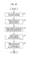
- FIG. 10 is a flowchart illustrating an exemplary process of changing a welding parameter during the checking operation. Assume that, in the checking operation, the operator holds and operates the teaching apparatus 40 with the left hand while holding a welding protection mask with the right hand.
- step 101 the operator presses any button provided in the button-providing area 46 of the teaching apparatus 40 and thus calls up a teaching program that has been taught to the welding robot 10 by the teaching apparatus 40.
- step 102 the operator holding the teaching apparatus 40 with the left hand presses the enabling switch 52a with at least any one of the left second, third, and fourth fingers and simultaneously presses the robot-manipulating portion 53 with the left first finger. If the operator keeps pressing the enabling switch 52a and the robot-manipulating portion 53, the teaching apparatus 40 sequentially advances the teaching program called up in step 101 and thus executes the program.
- the teaching apparatus 40 transmits the content of the program to be executed to the control apparatus 20, and the control apparatus 20 moves the welding robot 10 in accordance with the program received.
- step 103 after the operator has confirmed that an arc has been generated from the electrode at the welding start position that is set for the welding robot 10, the operator presses the screen change key 47 with the left thumb while keeping pressing the enabling switch 52a and the robot-manipulating portion 53.
- the screen change key 47 When the operator presses the screen change key 47, the screen illustrated in Fig. 8 appears on the display 43. Then, the operator changes the value of a welding parameter of interest, according to need, while observing the movement of the welding robot 10 that is executed in accordance with the teaching program.
- the operator To change a welding parameter, the operator first presses the change key 48a or the change key 48b in step 104 and thus selects a welding parameter the value of which the operator wants to change. After the operator has selected a welding parameter, the process proceeds to step 105 in which the operator presses the change key 48c or the change key 48d and thus change the value of the selected welding parameter. Then, the process ends.
- the operator changes the values of any welding parameters according to need while observing the movement of the welding robot 10. Subsequently, the actual welding operation is executed in accordance with the teaching program whose welding parameters have been adjusted such that an appropriate welding operation is executed.
- the teaching apparatus 40 includes the enabling switch 52a and the robot-manipulating portion 53 that are provided on the back face thereof, and the welding-parameter-manipulating portion 49 that is provided on the front face thereof. These buttons are arranged such that the operator can press all of them simultaneously with one hand. Even if the operator needs to hold a welding protection mask, the operator can hold the welding protection mask with the right hand while holding the teaching apparatus 40 with the left hand. Therefore, for example, the safety problem occurring in the teaching apparatus that needs to be operated with both hands is solved.
- the enabling switches 52 and the robot-manipulating portion 53 are each provided on a sloping surface. Furthermore, the width of the side face, i.e., the thickness of the teaching apparatus 40, is set such that the operator can easily hold the teaching apparatus 40, and the weight of the teaching apparatus 40 is set such that the operator can hold the teaching apparatus 40 for a long time with one hand. Such a configuration reduces the fatigue that the operator who has operated the teaching apparatus 40 for a long time suffers.
- the robot-manipulating portion 53 is employed as a button for advancing the teaching program and is provided on the back face of the teaching apparatus 40.
- a plurality of buttons for executing the movement of the welding robot 10, including an additional button for reversing the teaching program may be provided on the back face of the teaching apparatus 40.
- a button for switching the way of execution of the teaching program between the normal way and the reverse way may be provided within the reach of the thumb of the operator's left hand holding the teaching apparatus 40.
- the way of execution of the teaching program that is to be accepted by the robot-manipulating portion 53 is switchable between the normal way and the reverse way. That is, the robot-manipulating portion 53 can accept both the command for advancing the teaching program and the command for reversing the teaching program.
- the embodiment concerns a case where the welding-parameter-manipulating portion 49 includes the screen change key 47 and the change keys 48.
- the present invention is not limited to such a case.
- any buttons, other than the screen change key 47 and the change keys 48, may be included in the welding-parameter-manipulating portion 49 as long as such buttons are provided within the reach of the thumb of the operator's left hand placed under the strap 41 of the teaching apparatus 40 and are intended for changing parameters that define the movement of the welding robot 10.
- the embodiment concerns a case where the plurality of change keys 48 are arranged in a crisscross pattern.
- the present invention is not limited to such a case. Nevertheless, if the change keys 48 are arranged in a crisscross pattern, the operator only needs to press the change key 48a or 48b when selecting a welding parameter of interest, or to press the change key 48c or 48d when increasing or decreasing the value of the parameter. That is, the number of buttons that the operator needs to press is small. Such a configuration contributes to easy operation of the buttons with the thumb. Alternatively, for example, ten buttons representing numbers from 0 to 9, respectively, and allowing the operator to directly input a desired value may be provided as the change keys 48 within the reach of the operator's left thumb.
- the embodiment concerns a case where the strap 41 and the buttons are provided assuming that the operator holds the teaching apparatus 40 with the left hand.
- the present invention is not limited to such a case.
- the teaching apparatus 40 may be configured assuming that the operator holds the teaching apparatus 40 with the right hand.
- the strap 41 is provided on a portion of the right side face, in front view, of the teaching apparatus 40; the welding-parameter-manipulating portion 49 is provided on the right side, in front view, with respect to the center of the teaching apparatus 40; and the enabling switch 52a and the robot-manipulating portion 53 are provided on the left side, in rear view, with respect to the center of the teaching apparatus 40, that is, on the same side as the welding-parameter-manipulating portion 49 provided on the front face.
- the embodiment concerns a case where the welding-parameter-manipulating portion 49 is provided on the front face of the teaching apparatus 40 while the enabling switches 52 and the robot-manipulating portion 53 are provided on the back face of the teaching apparatus 40.
- the present invention is not limited to such a case.
- the teaching apparatus 40 only needs to be configured such that the operator holding the teaching apparatus 40 with one hand can operate the welding-parameter-manipulating portion 49, the enabling switch 52, and the robot-manipulating portion 53 with that hand.
- the teaching apparatus 40 only needs to be configured such that, in a state where the operator holding the teaching apparatus 40 with one hand is pressing the enabling switch 52, the welding-parameter-manipulating portion 49 and the robot-manipulating portion 53 are provided within the reach of at least any one of the fingers of that hand of the operator.
Abstract
Description
- The present invention relates to a teaching apparatus used for operation of an industrial robot.
- In general, when an industrial robot intended for welding is used, an operation for checking welding parameters is performed by moving the robot prior to actual welding operation. Such a checking operation is performed for optimizing the shape and the penetration of the bead by changing welding parameters, such as welding current, arc voltage, and welding speed, through a teaching apparatus. In the checking operation, the operator needs to check the state of the welded part during the welding operation and therefore performs the checking operation near the arm tip of the robot where arc is generated. Hence, in terms of safety, the checking operation is performed in a manual mode in which the robot is moved manually.
- International Organization of Standardization (ISO) provides requirements for performing the checking operation in the manual mode, one of which is specified in ISO 10218-1 5.7.4 as follows: "(the robot shall) provide a pendant conforming to 5.8 with a hold-to-run function in addition to the enabling device that permits robot motion to continue." The hold-to-run function is a function that permits the robot to move only when the function is operated manually with a hand of an operator, and stops the robot when the hand is released from the function. Hence, in the operation for checking the welding parameters, the operator changes any of the welding parameters while pressing both a switch (an enabling switch) of an enabling device that starts electrification of the robot and a button that permits the robot to move.
- An exemplary known teaching apparatus includes an enabling switch provided on the back face thereof and other operation buttons provided on the front face thereof. There are some known technologies that are each based on a consideration for ease of operation of such a teaching apparatus having an enabling switch on the back face thereof. For example, according to
Japanese Unexamined Patent Application Publication No. 2004-122243 Japanese Unexamined Patent Application Publication No. 2003-84864 - To move a robot manually by operating a teaching apparatus during an operation for checking welding parameters, the operator needs to press an enabling switch and a robot-activating button simultaneously. To change a welding parameter during the checking operation, an operation for changing the welding parameters needs to be performed additionally. That is, the operator needs to press a plurality of buttons during the operation of the teaching apparatus and therefore has to use both hands, not one hand. Moreover, to protect the face and other body parts from the arc, the operator occasionally holds a welding protection mask (face shield). In that case, the operator operates the teaching apparatus with the hand holding the welding protection mask. Such a situation is unfavorable in terms of safety.
- The present invention provides a teaching apparatus exhibiting improved ease of operation that allows the operator to easily change settings regarding the movement of a robot.
- According to an aspect of the present invention, there is provided a teaching apparatus that is connected to a control apparatus controlling a robot and outputs a command intended for the robot to the control apparatus. The teaching apparatus includes a setting-manipulating portion provided on a first face of the teaching apparatus and accepting an operation of changing a setting that defines a movement of the robot; an enabling switch provided on a second face of the teaching apparatus that is opposite the first face, the enabling switch accepting an operation of changing a state of electrification of the robot; and a robot-movement-manipulating portion provided on the second face and accepting an operation of executing the movement of the robot. Seen from a side of the first face, the setting-manipulating portion provided on the first face is positioned on a left side or a right side with respect to a center of the teaching apparatus, and the enabling switch and the robot-movement-manipulating portion provided on the second face are positioned on a same side as the setting-manipulating portion.
- In the teaching apparatus, it is preferable that a side face extending between the first face and the second face have a width that allows an operator to hold the teaching apparatus with one hand, the enabling switch be positioned in such a manner as to be operable with the one hand that is holding the teaching apparatus, the setting-manipulating portion be positioned within a reach of a thumb of the one hand in a state where the enabling switch is operated with at least any one of second, third, and fourth fingers of the one hand, and the robot-movement-manipulating portion be positioned within a reach of the first finger of the one hand in the state where the enabling switch is operated with at least any one of the second, third, and fourth fingers of the one hand.
- Furthermore, the teaching apparatus may include a display provided on the first face, and it is preferable that the setting-manipulating portion include a first button that accepts an operation of displaying, on the display, a screen for changing any of parameters defining a welding operation performed by the robot; a second button that accepts an operation of selecting one of the parameters displayed on the screen; and a third button that accepts an operation of changing a value of the selected parameter.
- Furthermore, in the teaching apparatus, it is preferable that the enabling switch and the robot-movement-manipulating portion be each provided at a position excluding a surface of the teaching apparatus that comes into contact with a flat surface if the teaching apparatus is placed on the flat surface with the second face facing the flat surface.
- Furthermore, the teaching apparatus may include a plate-like supporting portion provided between the enabling switch and the robot-movement-manipulating portion, the supporting portion supporting a first finger of one of operator's hands that is holding the teaching apparatus.
- Furthermore, in the teaching apparatus, it is preferable that the robot-movement-manipulating portion be positioned on a surface sloping at an angle of 5 degrees to 30 degrees with respect to a horizontal direction in a state where the teaching apparatus is placed on a flat surface with the second face facing the flat surface.
- Furthermore, in the teaching apparatus, it is preferable that the teaching apparatus have a weight of 1.2 kg or less and a thickness of 5 cm or smaller, the thickness corresponding to a width of a side face extending between the first face and the second face.
- Furthermore, in the teaching apparatus, it is preferable that an interval between the enabling switch and the robot-movement-manipulating portion be 5 cm or smaller.
- According to another aspect of the present invention, there is provided a teaching apparatus that is connected to a control apparatus controlling a robot and outputs a command intended for the robot to the control apparatus. The teaching apparatus includes a setting-manipulating portion that accepts an operation of changing a setting that defines a movement of the robot, an enabling switch that accepts an operation of changing a state of electrification of the robot, and a robot-movement-manipulating portion that accepts an operation of executing the movement of the robot. The enabling switch is positioned on one of two lateral sides with respect to a center of the teaching apparatus and in such a manner as to be operable with one of operator's hands that is holding the teaching apparatus. In a state where the teaching apparatus is held and the enabling switch is operated with the one hand, the setting-manipulating portion and the robot-movement-manipulating portion are each positioned within a reach of at least any one of a thumb and fingers of the one hand.
- According to each of the above aspects of the present invention, a teaching apparatus exhibiting improved ease of operation that allows the operator to easily change settings regarding the movement of a robot is provided.
-
-
Fig. 1 illustrates an exemplary outline configuration of a welding robot system according to an embodiment of the present invention; -
Fig. 2 is a perspective view of a teaching apparatus and illustrates an exemplary front appearance thereof; -
Fig. 3 is a perspective view of the teaching apparatus and illustrates an exemplary rear appearance thereof; -
Fig. 4 illustrates the exemplary front appearance of the teaching apparatus; -
Fig. 5 illustrates the exemplary rear appearance of the teaching apparatus; -
Fig. 6 illustrates an exemplary front appearance of the teaching apparatus that is held by a hand of an operator; -
Fig. 7 illustrates an exemplary rear appearance of the teaching apparatus that is held by the hand of the operator; -
Fig. 8 illustrates an exemplary screen for changing values of welding parameters; -
Fig. 9 illustrates an exemplary screen for setting the increment/decrement of each of the welding parameters; and -
Fig. 10 is a flowchart illustrating an exemplary process of changing a welding parameter during a checking operation. - An embodiment of the present invention will now be described in detail with reference to the accompanying drawings.
- A
welding robot system 1 according to the embodiment will first be described.Fig. 1 illustrates an exemplary outline configuration of thewelding robot system 1 according to the embodiment. - As illustrated in
Fig. 1 , thewelding robot system 1 includes a welding robot (manipulator) 10 that performs welding on a welding object (workpiece) by using an electrode, and a control apparatus (controller) 20 that controls thewelding robot 10. Thewelding robot system 1 further includes awelding power source 30 that supplies, for a welding operation, power to thewelding robot 10 and to the electrode held by awelding torch 11, and a teaching apparatus (teaching pendant) 40 that is used for purposes such as the creation of a teaching program that defines the movement of thewelding robot 10, and the determination of settings of the welding operation. Thecontrol apparatus 20 is connected to thewelding robot 10, thewelding power source 30, and theteaching apparatus 40 over a network. The communication between thecontrol apparatus 20 and theteaching apparatus 40 over the network may be either wired or wireless. - The
welding robot 10 includes an arm having a plurality of articulations and performs various operations relating to welding in accordance with teaching programs. The arm of thewelding robot 10 is provided at the tip thereof with thewelding torch 11 with which welding is performed on a workpiece W. - The
control apparatus 20 reads a pre-taught teaching program and controls the movement of thewelding robot 10. The teaching program is created by, for example, theteaching apparatus 40 or a separately prepared teaching-program-creating apparatus (not illustrated). Thecontrol apparatus 20 receives the teaching program over data communication. The teaching program may be provided to thecontrol apparatus 20 in the form of a removable storage medium such as a memory card. - Under the control of the
control apparatus 20, thewelding power source 30 supplies power to the electrode held by thewelding torch 11. With the power supplied from thewelding power source 30, the electrode on thewelding torch 11 included in thewelding robot 10 generates an arc. - The
teaching apparatus 40 has various buttons with which an operator creates a teaching program by inputting information such as welding parameters and welding paths, or makes various settings regarding the welding operation. On the basis of such manipulation performed by the operator, theteaching apparatus 40 outputs commands for moving thewelding robot 10 to thecontrol apparatus 20. Before the actual welding operation is executed in accordance with the teaching program by using thewelding robot 10, a checking operation is performed in which the movement of thewelding robot 10 that is to be made in the welding operation is checked in advance. In the checking operation, thewelding robot 10 moves in accordance with the pre-taught teaching program, and the operator checks whether or not thewelding robot 10 moves by following teaching points that are preset for the welding operation, whether or not the welding operation is properly performed by thewelding torch 11, and so forth. Then, if necessary, the operator corrects the teaching program by changing associated welding parameters so that thewelding robot 10 performs the welding operation properly. - The welding parameters that are to be changed include, for example, welding current, arc voltage, welding speed, weaving amplitude, weaving frequency, weaving stop time, the amount of shift in the weld line, and so forth. Welding current refers to a current flowing between the electrode and the workpiece W during the welding operation. Arc voltage refers to a voltage applied between the electrode and the workpiece W during the welding operation. Welding speed refers to a speed at which the
welding robot 10 moves. Weaving amplitude refers to an amplitude at which thewelding torch 11 weaves. Weaving frequency refers to the frequency of weaving per unit time. Weaving stop time refers to a time period for which the electrode stops on each of two sides between which the electrode weaves. The amount of shift in the weld line relates to multi-pass welding and refers to the amount by which the teaching point is shifted in the welding area. - A configuration of the
teaching apparatus 40 will now be described in detail.Fig. 2 is a perspective view of theteaching apparatus 40 and illustrates an exemplary front appearance thereof.Fig. 3 is a perspective view of theteaching apparatus 40 and illustrates an exemplary rear appearance thereof.Fig. 4 illustrates the exemplary front appearance of theteaching apparatus 40.Fig. 5 illustrates the exemplary rear appearance of theteaching apparatus 40. The vertical direction represented by the X axis inFigs. 2 to 5 corresponds to the longitudinal direction, i.e., the vertical direction, of theteaching apparatus 40. The lateral direction represented by the Y axis inFigs. 2 to 5 corresponds to the width direction, i.e., the lateral direction, of theteaching apparatus 40. In the embodiment, the front face of theteaching apparatus 40 corresponds to an exemplary first face, and the back face of theteaching apparatus 40 corresponds to an exemplary second face. - As illustrated in
Figs. 2 to 5 , theteaching apparatus 40 has a T shape and includes a casing having a certain thickness in the depth direction ofFigs. 4 and5 . Astrap 41 that helps the operator hold theteaching apparatus 40 is provided on a portion of the side face extending between the front face and the back face of theteaching apparatus 40. The width of the side face, i.e., the thickness of theteaching apparatus 40, is set such that the operator can hold theteaching apparatus 40. The operator holds theteaching apparatus 40 with the left hand placed under thestrap 41. The center of gravity of theteaching apparatus 40 is set at the center of theteaching apparatus 40 or at a position on the left side, inFig. 4 , with respect to the center of theteaching apparatus 40. Thus, the operator holding theteaching apparatus 40 with the left hand can stably operate theteaching apparatus 40. Aconnector 42 is provided on a lower left portion, in front view, of the side face of theteaching apparatus 40. A cable for connection to thecontrol apparatus 20 is to be inserted into theconnector 42. When the cable is inserted into theconnector 42, theteaching apparatus 40 is connected to thecontrol apparatus 20. When the cable is disconnected from theconnector 42, theteaching apparatus 40 alone can be carried around. - As illustrated in
Figs. 2 and4 , adisplay 43 is provided on the front face of theteaching apparatus 40 in a portion of the T shape that has the larger width. Information on the movement of thewelding robot 10, information on a teaching operation, and so forth are displayed on thedisplay 43. Thedisplay 43 may be a touch-panel display. Anemergency stop button 44 is provided on the upper right of the front face of theteaching apparatus 40. Theemergency stop button 44 is provided for stopping thewelding robot 10 in case of emergency. When theemergency stop button 44 is pressed by the operator, a command for emergency stop of thewelding robot 10 is issued. In response to the command, thecontrol apparatus 20 stops the driving of a motor of thewelding robot 10, and the movement of thewelding robot 10 is stopped. Referring toFig. 4 , astop key 45 is provided on the left side of thedisplay 43. Thestop key 45 is provided for pausing thewelding robot 10. When thestop key 45 is pressed by the operator, thecontrol apparatus 20 decelerates the movement of thewelding robot 10 while keeping the motor driving thewelding robot 10, and eventually stops thewelding robot 10. - The
teaching apparatus 40 includes a button-providingarea 46 in a portion of the T shape thereof that has the smaller width, i.e., a portion below thedisplay 43 in front view as illustrated inFig. 4 . Buttons for performing operations, such as the setting of the movement of thewelding robot 10, are provided in the button-providingarea 46. The buttons provided in the button-providingarea 46 may be of any type but are each preferably a sheet-type button so that the operator can operate the button quickly, with the depth to which the button is depressed being small. Nevertheless, to prevent the occurrence of operational errors, the buttons each preferably provide a tactile pressing sensation when pressed with a certain level of force. - The buttons provided in the button-providing
area 46 include, for example, ascreen change key 47, a change key 48a, a change key 48b, a change key 48c, a change key 48d (hereinafter collectively denoted aschange keys 48 if there is no need to distinguish them from one another), anadvance key 50, and areverse key 51. - The
screen change key 47 is provided for changing the screen that appears on thedisplay 43 and is used for displaying, for example, a screen for changing welding parameters on thedisplay 43. - The
change keys 48 are provided for changing welding parameters in the checking operation. - In the checking operation, when the operator has confirmed that the
welding robot 10 has started a welding operation and an arc has been generated, the operator presses thescreen change key 47, whereby the screen for changing welding parameters is displayed on thedisplay 43. If the operator observing the movement of thewelding robot 10 has determined that any of the welding parameters needs to be changed, the operator presses any of thechange keys 48 and changes that welding parameter. - The
change keys 48 are arranged in a crisscross pattern and include four buttons representing four directions, respectively. The change key 48a represents the upward direction. The change key 48b represents the downward direction. The change key 48c represents the leftward direction. The change key 48d represents the rightward direction. To change a welding parameter, for example, the operator presses the change key 48a representing the upward direction or the change key 48b representing the downward direction, thereby selecting an item whose value is desired to be changed among a plurality of items corresponding to the respective welding parameters. Subsequently, the operator presses the change key 48c representing the leftward direction or the change key 48d representing the rightward direction so as to increase or decrease the value of the selected item. Thus, the operator changes the value of a welding parameter. - Hereinafter, the
screen change key 47 and thechange keys 48 are collectively referred to as a welding-parameter-manipulatingportion 49. The welding-parameter-manipulatingportion 49 is used for changing settings, such as welding parameters, regarding the movement of thewelding robot 10. The welding-parameter-manipulatingportion 49 is provided in a portion on the left side, in front view, with respect to the center of theteaching apparatus 40. The welding-parameter-manipulatingportion 49 is positioned within the reach of the thumb of the operator's left hand placed under thestrap 41 of theteaching apparatus 40, and within an area where the operator can move the thumb freely with no discomfort. The welding-parameter-manipulatingportion 49 according to the embodiment is an exemplary setting-manipulating portion. Furthermore, thescreen change key 47 is an exemplary first button, the change key 48a and the change key 48b are exemplary second buttons, and the change key 48c and the change key 48d are exemplary third buttons. - The advance key 50 advances the teaching program and executes the movement of the
welding robot 10 in accordance with the teaching program. - The reverse key 51 reverses the teaching program and causes the
welding robot 10 to move in the reverse way. - Referring to
Figs. 3 and5 , theteaching apparatus 40 has a recess in the back face, opposite the front face, thereof in a portion of the T shape that has the smaller width. An enablingswitch 52a, an enablingswitch 52b (hereinafter collectively denoted as enablingswitches 52 if there is no need to distinguish them from each other), a robot-manipulatingportion 53, and a supportingportion 54 are provided in the recess. - The enabling switches 52 are provided for changing the state of electrification of the
welding robot 10. To manually move thewelding robot 10 in the checking operation, the operator needs to keep pressing the enablingswitch 52a or the enablingswitch 52b so that thewelding robot 10 is kept electrified. The enabling switches 52 are each positioned on one of two lateral sides with respect to the center of theteaching apparatus 40. The enablingswitch 52a is on the right side, in rear view, with respect to the center of theteaching apparatus 40, that is, on the same side as the welding-parameter-manipulatingportion 49 provided on the front face of theteaching apparatus 40. The enablingswitch 52b is provided on the left side, in rear view, with respect to the center of theteaching apparatus 40. That is, the enablingswitch 52a is positioned in such a manner as to be operable with the operator's left hand holding theteaching apparatus 40. - The shape of each of the enabling switches 52 is not specifically limited but is preferably a rectangular parallelepiped shape with a surface on which the operator's fingers are to be placed being flat so that the operator can easily press the enabling
switch 52 with a plurality of fingers. The enabling switches 52 are each provided on a sloping surface that slopes with respect to the Y-axis direction. More specifically, in a state where theteaching apparatus 40 is placed face up on a flat surface, the enabling switches 52 are each not provided on a surface that comes into contact with the flat surface but are each provided on a surface sloping with respect to the surface of contact extending in the horizontal direction (the Y-axis direction). - Providing each of the enabling switches 52 on a sloping surface makes it easier for the operator who is holding the
teaching apparatus 40 with the left hand to keep pressing the enablingswitch 52a than in a configuration in which, for example, the enablingswitch 52a is provided on a flat surface extending in the Y-axis direction. In the configuration in which the enabling switches 52 are each provided on a flat surface extending in the Y-axis direction, if the operator places theteaching apparatus 40 face up on a flat surface, the enabling switches 52 may be pressed accidentally. Hence, the enabling switches 52 are each provided on a sloping surface. Thus, an operational error that may occur when theteaching apparatus 40 is placed somewhere is prevented. - Each of the enabling switches 52 can be depressed to a plurality of depths. When the enabling
switch 52 is depressed to a first depth, thewelding robot 10 is electrified as described above. When the enablingswitch 52 is depressed further to a second depth by the operator, a command for pausing thewelding robot 10 is issued. - The robot-manipulating
portion 53 is provided for advancing the teaching program and thus executing the movement of thewelding robot 10 in accordance with the teaching program. That is, the robot-manipulatingportion 53 has the same function as theadvance key 50. To manually move thewelding robot 10 in the checking operation, the operator needs to keep pressing both the enablingswitch 52 and a button for advancing the teaching program (i.e., theadvance key 50 or the robot-manipulating portion 53). If the operator is holding theteaching apparatus 40 with the left hand, the operator has to use the right hand to press theadvance key 50 but can use the left hand to press the robot-manipulatingportion 53. Hence, the operator moves thewelding robot 10 by pressing both the enablingswitch 52a and the robot-manipulatingportion 53 with the left hand. - The robot-manipulating
portion 53 is provided above the enablingswitch 52a and on the right side, in rear view, with respect to the center of theteaching apparatus 40, that is, on the same side as the welding-parameter-manipulatingportion 49 provided on the front face of theteaching apparatus 40. The robot-manipulatingportion 53 is positioned within the reach of the left first finger of the operator who is holding theteaching apparatus 40 with the left hand placed under thestrap 41 and is pressing the enablingswitch 52a with at least any one of the left second, third, and fourth fingers. Likewise, the welding-parameter-manipulatingportion 49 is positioned within the reach of the left thumb of the operator who is holding theteaching apparatus 40 with the left hand placed under thestrap 41 and is pressing the enablingswitch 52a with at least any one of the left second, third, and fourth fingers. That is, the operator holding theteaching apparatus 40 with the left hand can press the welding-parameter-manipulatingportion 49 with the left thumb while pressing the robot-manipulatingportion 53 with the left first finger and the enablingswitch 52a with at least any one of the left second, third, and fourth fingers. - The robot-manipulating
portion 53 is provided on a sloping surface that slopes with respect to the Y-axis direction, as with the enabling switches 52. More specifically, in the state where theteaching apparatus 40 is placed face up on a flat surface, the robot-manipulatingportion 53 is not provided on a surface that comes into contact with the flat surface but is provided on a surface sloping with respect to the surface of contact extending in the horizontal direction. Providing the robot-manipulatingportion 53 on a sloping surface makes it easier for the operator who is holding theteaching apparatus 40 with the left hand to keep pressing the robot-manipulatingportion 53 than in a configuration in which, for example, the robot-manipulatingportion 53 is provided on a flat surface extending in the Y-axis direction. Furthermore, as with the case of the enablingswitch 52, providing the robot-manipulatingportion 53 on a sloping surface prevents an operational error that may occur when theteaching apparatus 40 is placed somewhere. - The robot-manipulating
portion 53 is preferably provided on a surface sloping at an angle from 5 degrees to 30 degrees with respect to the Y axis. If the angle of slope of the surface falls below 5 degrees, the difference between the angle of bend in the first finger pressing the robot-manipulatingportion 53 and the angle of bend in the finger (any of the second, third, and fourth fingers) pressing the enablingswitch 52a becomes large. If the operator keeps pressing the robot-manipulatingportion 53 for a long time in such a state, the fatigue that the first finger suffers increases. On the other hand, if the angle of slope of the surface exceeds 30 degrees, the angle of bend in the first finger becomes too large. If the operator keeps pressing the robot-manipulatingportion 53 for a long time in such a state, the fatigue that the first finger suffers increases. Moreover, according to an experiment, it has been found that the preferable angle of slope of the robot-manipulatingportion 53 with respect to the Y axis is 15 degrees. - Designing the robot-manipulating
portion 53 so as to be depressible deeply by the operator or employing, as the robot-manipulatingportion 53, a button that is turned on by being depressed only shallowly reduces the burden imposed on the first finger of the operator and makes it easier for the operator to keep pressing the robot-manipulatingportion 53. In the embodiment, the robot-manipulatingportion 53 is employed as an exemplary robot-movement-manipulating portion. - The supporting
portion 54 has a plate-like shape and is provided between the robot-manipulatingportion 53 and the enablingswitch 52a. The operator presses the robot-manipulatingportion 53 with the first finger being supported by the supportingportion 54. More specifically, since the robot-manipulatingportion 53 is provided in the recess of theteaching apparatus 40, the robot-manipulatingportion 53 is surrounded by walls of the recess on the upper side and the right side and the supportingportion 54, whereby a space for receiving the first finger is provided at the robot-manipulatingportion 53. Hence, the operator can place the first finger on the supportingportion 54. Thus, the operator can press the robot-manipulatingportion 53 more easily and the fatigue that the first finger suffers becomes smaller than in a case where, for example, the supportingportion 54 is not provided. Furthermore, providing the supportingportion 54 allows the operator to easily find the position of the robot-manipulatingportion 53 without checking it visually but only by feeling around with the first finger. In addition, the supportingportion 54 can be used as a rest for the first finger when there is no need for the operator holding theteaching apparatus 40 to press the robot-manipulatingportion 53. - How the operator holds the
teaching apparatus 40 will now be described.Fig. 6 illustrates an exemplary front appearance of theteaching apparatus 40 that is held by a hand of the operator.Fig. 7 illustrates an exemplary rear appearance of theteaching apparatus 40 that is held by the hand of the operator. - As illustrated in
Figs. 6 and7 , during the checking operation, the operator holds theteaching apparatus 40 with the left hand placed under thestrap 41 and presses the enablingswitch 52 and the robot-manipulatingportion 53 that are provided on the back face of theteaching apparatus 40. When the operator presses the enablingswitch 52 and the robot-manipulatingportion 53, a pre-taught teaching program is executed by thecontrol apparatus 20, whereby thewelding robot 10 starts to move. To change any welding parameters while the operator is checking the movement of thewelding robot 10, the operator presses the welding-parameter-manipulatingportion 49 provided on the front face of theteaching apparatus 40 while pressing the enablingswitch 52 and the robot-manipulatingportion 53. - The operator occasionally holds a welding protection mask with one hand so as to protect the face and other body parts from the arc generated during the checking operation. Therefore, the buttons of the
teaching apparatus 40 according to the embodiment are arranged such that the operator can easily operate the buttons with one hand. Specifically, the operator holds theteaching apparatus 40 with the left hand, presses the enablingswitch 52a with at least any one of the left second, third, and fourth fingers, and presses the robot-manipulatingportion 53 with the left first finger, thereby advancing the movement of thewelding robot 10. Furthermore, while the operator keeps pressing the enablingswitch 52a and the robot-manipulatingportion 53 with the left hand, the operator changes welding parameters by pressing buttons provided in the welding-parameter-manipulatingportion 49 with the left thumb. - More specifically, to change a welding parameter, the operator presses the
screen change key 47 provided in the welding-parameter-manipulatingportion 49 with the left thumb while pressing the enablingswitch 52a and the robot-manipulatingportion 53. When thescreen change key 47 is pressed, a screen for changing welding parameters appears. Then, the operator presses any of thechange keys 48 with the left thumb while pressing the enablingswitch 52a and the robot-manipulatingportion 53, thereby increasing or decreasing the value of the welding parameter of interest, with thewelding robot 10 moving. - The width of the side face of the
teaching apparatus 40, i.e., the thickness of theteaching apparatus 40, is preferably 5 cm or smaller, for example. If the thickness of theteaching apparatus 40 exceeds 5 cm, it becomes difficult for the operator's fingers to reach any of the enablingswitch 52a, the robot-manipulatingportion 53, and the welding-parameter-manipulatingportion 49 and to press the three buttons simultaneously. In contrast, if the thickness of theteaching apparatus 40 falls below 0.5 cm, it becomes difficult to hold theteaching apparatus 40. Hence, in terms of ease of holding, the thickness of theteaching apparatus 40 is preferably determined within the range of 0.5 cm to 5 cm. Furthermore, the weight of theteaching apparatus 40 is preferably 1.2 kg or less, for example. If the weight of theteaching apparatus 40 exceeds 1.2 kg, it becomes difficult for the operator to hold theteaching apparatus 40 for a long time with one hand. There is no lower limit for the weight of theteaching apparatus 40 because the lighter, the better. - The enabling
switch 52a and the robot-manipulatingportion 53 are preferably positioned close to each other with an interval of, for example, 5 cm or smaller. If the interval between the two buttons exceeds 5 cm, it becomes difficult for the operator to press the enablingswitch 52a with any of the second, third, and fourth fingers while pressing the robot-manipulatingportion 53 with the first finger. - Screens that appear on the
display 43 of theteaching apparatus 40 during the checking operation will now be described.Fig. 8 illustrates an exemplary screen for changing values of the welding parameters.Fig. 9 illustrates an exemplary screen for setting the increment/decrement of each of the welding parameters. - For example, the screen illustrated in
Fig. 8 appears after the checking operation is started and when the operator who has confirmed the generation of an arc has pressed thescreen change key 47 with the thumb. This screen provides a list of the welding parameters whose values are changeable. In the exemplary screen illustrated inFig. 8 , the welding parameters include welding current, arc voltage, welding speed, weaving amplitude, weaving frequency, and weaving stop time. - The current values of the respective welding parameters are set as follows: welding current is 350 ampere (unit symbol: A), arc voltage is 100%, welding speed is 35 cm/min, weaving amplitude is 3 mm, weaving frequency is 100 times/min, and weaving stop time is 0.1 sec. Regarding the settings of welding current and arc voltage, an integrated adjustment method is employed in which, when a value is set for welding current, a value for arc voltage that corresponds to the set welding current is automatically set. The voltage that is most suitable for the set welding current is represented as 100%.
- On the above screen, the operator presses the change key 48a or the change key 48b so as to select a welding parameter whose value is desired to be changed. On the screen illustrated in
Fig. 8 , the item "welding current" enclosed by aframe 61 is currently selected. If the operator presses the change key 48b once, theframe 61 moves down by one item to arc voltage. If the operator presses the change key 48a once with the item "arc voltage" being selected, theframe 61 moves up by one item to welding current. For example, in a state where welding current is selected, the operator changes the value of welding current by pressing the change key 48c or the change key 48d. For example, when the operator presses the change key 48c, the value of welding current increases. When the operator presses the change key 48d, the value of welding current decreases. If the operator changes any values, thewelding robot 10 moves in accordance with the changed values and the checking operation continues. - The screen illustrated in
Fig. 9 provides the increment/decrement by which each of the welding parameters is increased or decreased. When the operator presses the change key 48c or the change key 48d once, the value of the welding parameter increases or decreases by the increment or decrement. The increment/decrement is set for each of the welding parameters by the operator in advance, for example, prior to the checking operation. The current increments/decrements for the respective welding parameters listed on the exemplary screen illustrated inFig. 9 are as follows: 5 A for welding current, 1% for arc voltage, 1.0 cm/min for welding speed, 1 mm for weaving amplitude, one time/min for weaving frequency, and 0.1 sec for weaving stop time. - A process of changing a welding parameter during the checking operation will now be described.
Fig. 10 is a flowchart illustrating an exemplary process of changing a welding parameter during the checking operation. Assume that, in the checking operation, the operator holds and operates theteaching apparatus 40 with the left hand while holding a welding protection mask with the right hand. - First, in
step 101, the operator presses any button provided in the button-providingarea 46 of theteaching apparatus 40 and thus calls up a teaching program that has been taught to thewelding robot 10 by theteaching apparatus 40. Subsequently, instep 102, the operator holding theteaching apparatus 40 with the left hand presses the enablingswitch 52a with at least any one of the left second, third, and fourth fingers and simultaneously presses the robot-manipulatingportion 53 with the left first finger. If the operator keeps pressing the enablingswitch 52a and the robot-manipulatingportion 53, theteaching apparatus 40 sequentially advances the teaching program called up instep 101 and thus executes the program. In this step, theteaching apparatus 40 transmits the content of the program to be executed to thecontrol apparatus 20, and thecontrol apparatus 20 moves thewelding robot 10 in accordance with the program received. - Subsequently, in
step 103, after the operator has confirmed that an arc has been generated from the electrode at the welding start position that is set for thewelding robot 10, the operator presses thescreen change key 47 with the left thumb while keeping pressing the enablingswitch 52a and the robot-manipulatingportion 53. When the operator presses thescreen change key 47, the screen illustrated inFig. 8 appears on thedisplay 43. Then, the operator changes the value of a welding parameter of interest, according to need, while observing the movement of thewelding robot 10 that is executed in accordance with the teaching program. - To change a welding parameter, the operator first presses the change key 48a or the change key 48b in
step 104 and thus selects a welding parameter the value of which the operator wants to change. After the operator has selected a welding parameter, the process proceeds to step 105 in which the operator presses the change key 48c or the change key 48d and thus change the value of the selected welding parameter. Then, the process ends. - As described above, in the checking operation, the operator changes the values of any welding parameters according to need while observing the movement of the
welding robot 10. Subsequently, the actual welding operation is executed in accordance with the teaching program whose welding parameters have been adjusted such that an appropriate welding operation is executed. - To summarize, the
teaching apparatus 40 according to the embodiment includes the enablingswitch 52a and the robot-manipulatingportion 53 that are provided on the back face thereof, and the welding-parameter-manipulatingportion 49 that is provided on the front face thereof. These buttons are arranged such that the operator can press all of them simultaneously with one hand. Even if the operator needs to hold a welding protection mask, the operator can hold the welding protection mask with the right hand while holding theteaching apparatus 40 with the left hand. Therefore, for example, the safety problem occurring in the teaching apparatus that needs to be operated with both hands is solved. - In the
teaching apparatus 40, the enabling switches 52 and the robot-manipulatingportion 53 are each provided on a sloping surface. Furthermore, the width of the side face, i.e., the thickness of theteaching apparatus 40, is set such that the operator can easily hold theteaching apparatus 40, and the weight of theteaching apparatus 40 is set such that the operator can hold theteaching apparatus 40 for a long time with one hand. Such a configuration reduces the fatigue that the operator who has operated theteaching apparatus 40 for a long time suffers. - According to the embodiment, the robot-manipulating
portion 53 is employed as a button for advancing the teaching program and is provided on the back face of theteaching apparatus 40. As a modification, a plurality of buttons for executing the movement of thewelding robot 10, including an additional button for reversing the teaching program, may be provided on the back face of theteaching apparatus 40. Alternatively, for example, a button for switching the way of execution of the teaching program between the normal way and the reverse way may be provided within the reach of the thumb of the operator's left hand holding theteaching apparatus 40. In that case, the way of execution of the teaching program that is to be accepted by the robot-manipulatingportion 53 is switchable between the normal way and the reverse way. That is, the robot-manipulatingportion 53 can accept both the command for advancing the teaching program and the command for reversing the teaching program. - The embodiment concerns a case where the welding-parameter-manipulating
portion 49 includes thescreen change key 47 and thechange keys 48. However, the present invention is not limited to such a case. For example, any buttons, other than thescreen change key 47 and thechange keys 48, may be included in the welding-parameter-manipulatingportion 49 as long as such buttons are provided within the reach of the thumb of the operator's left hand placed under thestrap 41 of theteaching apparatus 40 and are intended for changing parameters that define the movement of thewelding robot 10. - The embodiment concerns a case where the plurality of
change keys 48 are arranged in a crisscross pattern. However, the present invention is not limited to such a case. Nevertheless, if thechange keys 48 are arranged in a crisscross pattern, the operator only needs to press the change key 48a or 48b when selecting a welding parameter of interest, or to press the change key 48c or 48d when increasing or decreasing the value of the parameter. That is, the number of buttons that the operator needs to press is small. Such a configuration contributes to easy operation of the buttons with the thumb. Alternatively, for example, ten buttons representing numbers from 0 to 9, respectively, and allowing the operator to directly input a desired value may be provided as thechange keys 48 within the reach of the operator's left thumb. - The embodiment concerns a case where the
strap 41 and the buttons are provided assuming that the operator holds theteaching apparatus 40 with the left hand. However, the present invention is not limited to such a case. For example, theteaching apparatus 40 may be configured assuming that the operator holds theteaching apparatus 40 with the right hand. In that case, for example, thestrap 41 is provided on a portion of the right side face, in front view, of theteaching apparatus 40; the welding-parameter-manipulatingportion 49 is provided on the right side, in front view, with respect to the center of theteaching apparatus 40; and the enablingswitch 52a and the robot-manipulatingportion 53 are provided on the left side, in rear view, with respect to the center of theteaching apparatus 40, that is, on the same side as the welding-parameter-manipulatingportion 49 provided on the front face. - The embodiment concerns a case where the welding-parameter-manipulating
portion 49 is provided on the front face of theteaching apparatus 40 while the enabling switches 52 and the robot-manipulatingportion 53 are provided on the back face of theteaching apparatus 40. However, the present invention is not limited to such a case. Theteaching apparatus 40 only needs to be configured such that the operator holding theteaching apparatus 40 with one hand can operate the welding-parameter-manipulatingportion 49, the enablingswitch 52, and the robot-manipulatingportion 53 with that hand. That is, theteaching apparatus 40 only needs to be configured such that, in a state where the operator holding theteaching apparatus 40 with one hand is pressing the enablingswitch 52, the welding-parameter-manipulatingportion 49 and the robot-manipulatingportion 53 are provided within the reach of at least any one of the fingers of that hand of the operator. - While an embodiment of the present invention has been described above, the technical scope of the present invention is not limited to the above embodiment. It is obvious to those skilled in the art that the present invention can be modified or embodied in various other ways without departing from the spirit and the scope thereof.
Claims (10)
- A teaching apparatus that is connected to a control apparatus controlling a robot and outputs a command intended for the robot to the control apparatus, the teaching apparatus comprising:a setting-manipulating portion provided on a first face of the teaching apparatus and accepting an operation of changing a setting that defines a movement of the robot;an enabling switch provided on a second face of the teaching apparatus that is opposite the first face, the enabling switch accepting an operation of changing a state of electrification of the robot; anda robot-movement-manipulating portion provided on the second face and accepting an operation of executing the movement of the robot,wherein, seen from a side of the first face, the setting-manipulating portion provided on the first face is positioned on a left side or a right side with respect to a center of the teaching apparatus, and the enabling switch and the robot-movement-manipulating portion provided on the second face are positioned on a same side as the setting-manipulating portion.
- The teaching apparatus according to Claim 1,
wherein a side face extending between the first face and the second face has a width that allows an operator to hold the teaching apparatus with one hand,
wherein the enabling switch is positioned in such a manner as to be operable with the one hand that is holding the teaching apparatus,
wherein the setting-manipulating portion is positioned within a reach of a thumb of the one hand in a state where the enabling switch is operated with at least any one of second, third, and fourth fingers of the one hand, and
wherein the robot-movement-manipulating portion is positioned within a reach of the first finger of the one hand in the state where the enabling switch is operated with at least any one of the second, third, and fourth fingers of the one hand. - The teaching apparatus according to Claim 1, further comprising:a display provided on the first face,wherein the setting-manipulating portion includesa first button that accepts an operation of displaying, on the display, a screen for changing any of parameters defining a welding operation performed by the robot;a second button that accepts an operation of selecting one of the parameters displayed on the screen; anda third button that accepts an operation of changing a value of the selected parameter.
- The teaching apparatus according to Claim 2, further comprising:a display provided on the first face,wherein the setting-manipulating portion includesa first button that accepts an operation of displaying, on the display, a screen for changing any of parameters defining a welding operation performed by the robot;a second button that accepts an operation of selecting one of the parameters displayed on the screen; anda third button that accepts an operation of changing a value of the selected parameter.
- The teaching apparatus according to any of Claims 1 to 4, wherein the enabling switch and the robot-movement-manipulating portion are each provided at a position excluding a surface of the teaching apparatus that comes into contact with a flat surface if the teaching apparatus is placed on the flat surface with the second face facing the flat surface.
- The teaching apparatus according to any of Claims 1 to 4, further comprising a plate-like supporting portion provided between the enabling switch and the robot-movement-manipulating portion, the supporting portion supporting a first finger of one of operator's hands that is holding the teaching apparatus.
- The teaching apparatus according to any of Claims 1 to 4, wherein the robot-movement-manipulating portion is positioned on a surface sloping at an angle of 5 degrees to 30 degrees with respect to a horizontal direction in a state where the teaching apparatus is placed on a flat surface with the second face facing the flat surface.
- The teaching apparatus according to any of Claims 1 to 4, wherein the teaching apparatus has a weight of 1.2 kg or less and a thickness of 5 cm or smaller, the thickness corresponding to a width of a side face extending between the first face and the second face.
- The teaching apparatus according to any of Claims 1 to 4, wherein an interval between the enabling switch and the robot-movement-manipulating portion is 5 cm or smaller.
- A teaching apparatus that is connected to a control apparatus controlling a robot and outputs a command intended for the robot to the control apparatus, the teaching apparatus comprising:a setting-manipulating portion that accepts an operation of changing a setting that defines a movement of the robot;an enabling switch that accepts an operation of changing a state of electrification of the robot; anda robot-movement-manipulating portion that accepts an operation of executing the movement of the robot,wherein the enabling switch is positioned on one of two lateral sides with respect to a center of the teaching apparatus and in such a manner as to be operable with one of operator's hands that is holding the teaching apparatus, andwherein, in a state where the teaching apparatus is held and the enabling switch is operated with the one hand, the setting-manipulating portion and the robot-movement-manipulating portion are each positioned within a reach of at least any one of a thumb and fingers of the one hand.
Applications Claiming Priority (1)
| Application Number | Priority Date | Filing Date | Title |
|---|---|---|---|
| JP2014237038A JP6208114B2 (en) | 2014-11-21 | 2014-11-21 | Teaching device used for operation of industrial robots |
Publications (2)
| Publication Number | Publication Date |
|---|---|
| EP3029534A1 true EP3029534A1 (en) | 2016-06-08 |
| EP3029534B1 EP3029534B1 (en) | 2019-02-13 |
Family
ID=54364952
Family Applications (1)
| Application Number | Title | Priority Date | Filing Date |
|---|---|---|---|
| EP15003042.7A Active EP3029534B1 (en) | 2014-11-21 | 2015-10-23 | Teaching apparatus used for operation of industrial robot |
Country Status (5)
| Country | Link |
|---|---|
| US (1) | US10780580B2 (en) |
| EP (1) | EP3029534B1 (en) |
| JP (1) | JP6208114B2 (en) |
| KR (1) | KR101850191B1 (en) |
| CN (1) | CN105619423B (en) |
Families Citing this family (11)
| Publication number | Priority date | Publication date | Assignee | Title |
|---|---|---|---|---|
| JP6514258B2 (en) * | 2017-03-31 | 2019-05-15 | ファナック株式会社 | Robot system |
| JP6824855B2 (en) * | 2017-09-29 | 2021-02-03 | 株式会社安川電機 | Operation unit and robot |
| JP6937651B2 (en) * | 2017-10-02 | 2021-09-22 | 株式会社ダイヘン | Welding robot operation terminal and welding robot system |
| JP1606242S (en) * | 2017-11-22 | 2018-06-11 | ||
| JP7026495B2 (en) * | 2017-11-28 | 2022-02-28 | 株式会社ダイヘン | Portable operating device |
| CN110000751A (en) * | 2018-01-05 | 2019-07-12 | 天津职业技术师范大学 | A kind of teaching device of mechanical automation industrial robot |
| CN108748167B (en) * | 2018-08-15 | 2024-03-12 | 江苏华途数控科技有限公司 | Industrial robot demonstrator suitable for single-hand operation |
| US20200368904A1 (en) * | 2019-05-20 | 2020-11-26 | Russell Aldridge | Remote robotic welding with a handheld controller |
| CN110293539B (en) * | 2019-06-24 | 2022-09-30 | 佛山智异科技开发有限公司 | Method and device for realizing software architecture of industrial robot demonstrator and demonstrator |
| JP7277294B2 (en) * | 2019-07-09 | 2023-05-18 | ファナック株式会社 | A safety switch device attached to a portable terminal for operating a machine and a machine operation device equipped with the safety switch device |
| CN114619425A (en) * | 2020-12-08 | 2022-06-14 | 山东新松工业软件研究院股份有限公司 | Demonstrator main control board and novel clean robot demonstrator |
Citations (6)
| Publication number | Priority date | Publication date | Assignee | Title |
|---|---|---|---|---|
| EP0909616A1 (en) * | 1997-04-01 | 1999-04-21 | Fanuc Ltd | Teaching control panel for robot |
| US6134102A (en) * | 1995-07-22 | 2000-10-17 | Kuka Roboter Gmbh | Programming device |
| JP2003084864A (en) | 2001-09-10 | 2003-03-19 | Digital Electronics Corp | Portable operation device |
| EP1406139A2 (en) * | 2002-10-04 | 2004-04-07 | COMAU S.p.A. | Portable programming terminal for robots or similar automatic apparatuses |
| JP2004122243A (en) | 2002-09-30 | 2004-04-22 | Yaskawa Electric Corp | One-hand instruction device |
| FR2852442A1 (en) * | 2003-03-11 | 2004-09-17 | Staubli Sa Ets | Multi-axis robot control casing, has push button operated by hand, and two distinct series of control switches controlling displacement of one part of robot translating along one direction or in rotation around geometrical axis |
Family Cites Families (15)
| Publication number | Priority date | Publication date | Assignee | Title |
|---|---|---|---|---|
| JPH0688219B2 (en) * | 1987-10-02 | 1994-11-09 | 株式会社日立製作所 | Portable teaching device |
| JP3263819B2 (en) * | 1991-12-13 | 2002-03-11 | ヤマハ発動機株式会社 | Portable teaching device |
| JP4036246B2 (en) | 1994-08-02 | 2008-01-23 | 任天堂株式会社 | Game console operating device |
| JP3618375B2 (en) * | 1994-09-19 | 2005-02-09 | 株式会社安川電機 | Handheld controller |
| US5874906A (en) * | 1997-09-22 | 1999-02-23 | Wilnel, Inc. | Data entry system |
| AT412176B (en) * | 2001-06-26 | 2004-10-25 | Keba Ag | PORTABLE DEVICE AT LEAST FOR VISUALIZING PROCESS DATA FROM A MACHINE, A ROBOT OR A TECHNICAL PROCESS |
| SE0103251D0 (en) * | 2001-10-01 | 2001-10-01 | Abb Ab | Industrial robot system comprising a programmable unit |
| ITTO20020863A1 (en) | 2002-10-04 | 2004-04-05 | Comau Spa | PORTABLE TERMINAL OF COMMAND, PROGRAMMING AND / OR |
| SE531329C2 (en) * | 2005-06-20 | 2009-02-24 | Yaskawa Denki Seisakusho Kk | Automatic machine system and method for controlling its communication |
| US8669935B2 (en) * | 2009-09-17 | 2014-03-11 | Sony Corporation | Operation device |
| US8258917B2 (en) * | 2010-03-03 | 2012-09-04 | Measurement Systems, Inc. | Intuitive multiple degrees of freedom portable control device |
| JP2012110995A (en) | 2010-11-24 | 2012-06-14 | Kyokko Denki Kk | Operation teaching device which can teach operation by finger touch |
| JP5871372B2 (en) * | 2012-01-12 | 2016-03-01 | 株式会社ダイヘン | Arc welding equipment |
| US10081109B2 (en) * | 2012-09-06 | 2018-09-25 | Fanuc America Corporation | Haptic teach pendant |
| JP5642304B2 (en) * | 2013-02-15 | 2014-12-17 | 株式会社神戸製鋼所 | Robot pendant |
-
2014
- 2014-11-21 JP JP2014237038A patent/JP6208114B2/en active Active
-
2015
- 2015-10-05 US US14/874,699 patent/US10780580B2/en active Active
- 2015-10-23 EP EP15003042.7A patent/EP3029534B1/en active Active
- 2015-11-17 CN CN201510789209.5A patent/CN105619423B/en active Active
- 2015-11-19 KR KR1020150162179A patent/KR101850191B1/en active IP Right Grant
Patent Citations (6)
| Publication number | Priority date | Publication date | Assignee | Title |
|---|---|---|---|---|
| US6134102A (en) * | 1995-07-22 | 2000-10-17 | Kuka Roboter Gmbh | Programming device |
| EP0909616A1 (en) * | 1997-04-01 | 1999-04-21 | Fanuc Ltd | Teaching control panel for robot |
| JP2003084864A (en) | 2001-09-10 | 2003-03-19 | Digital Electronics Corp | Portable operation device |
| JP2004122243A (en) | 2002-09-30 | 2004-04-22 | Yaskawa Electric Corp | One-hand instruction device |
| EP1406139A2 (en) * | 2002-10-04 | 2004-04-07 | COMAU S.p.A. | Portable programming terminal for robots or similar automatic apparatuses |
| FR2852442A1 (en) * | 2003-03-11 | 2004-09-17 | Staubli Sa Ets | Multi-axis robot control casing, has push button operated by hand, and two distinct series of control switches controlling displacement of one part of robot translating along one direction or in rotation around geometrical axis |
Also Published As
| Publication number | Publication date |
|---|---|
| EP3029534B1 (en) | 2019-02-13 |
| US20160144513A1 (en) | 2016-05-26 |
| JP2016097482A (en) | 2016-05-30 |
| US10780580B2 (en) | 2020-09-22 |
| CN105619423B (en) | 2018-11-09 |
| KR101850191B1 (en) | 2018-04-18 |
| CN105619423A (en) | 2016-06-01 |
| JP6208114B2 (en) | 2017-10-04 |
| KR20160061266A (en) | 2016-05-31 |
Similar Documents
| Publication | Publication Date | Title |
|---|---|---|
| US10780580B2 (en) | Teaching apparatus used for operation of industrial robot | |
| EP1405700B1 (en) | Portable terminal for controlling, programming and/or teaching robots or similar automatic apparatuses | |
| EP1406139B1 (en) | System for programming robots or similar automatic apparatuses, comprising a portable programming terminal | |
| US10478965B2 (en) | Robot system | |
| JP6642054B2 (en) | Robot operation device and robot operation program | |
| US20210039185A1 (en) | System for controlling welding parameter of a welding system | |
| CN107486607A (en) | Method and apparatus for setting welding parameter | |
| JP5547457B2 (en) | Motion input device | |
| US9089923B2 (en) | Control system for welder | |
| KR101909226B1 (en) | Arc welding equipment | |
| JPH11262884A (en) | Manual operation device for robot | |
| JP6705091B2 (en) | Thermal processing torch and thermal processing system | |
| US20200198042A1 (en) | Welding torch and welding system | |
| CN107921567B (en) | Welding condition setting method and welding condition setting device | |
| KR101960064B1 (en) | Arc welding equipment | |
| JP6826153B2 (en) | Robot teaching device | |
| KR102256584B1 (en) | Welding machine | |
| JP6851950B2 (en) | Display device, welding torch, wire feeder, and relay device | |
| JP5912054B2 (en) | Robot controller | |
| JP7147302B2 (en) | Thermal processing system and thermal processing torch | |
| WO2018225519A1 (en) | Welding conditions setting device and welding conditions setting method |
Legal Events
| Date | Code | Title | Description |
|---|---|---|---|
| PUAI | Public reference made under article 153(3) epc to a published international application that has entered the european phase |
Free format text: ORIGINAL CODE: 0009012 |
|
| AK | Designated contracting states |
Kind code of ref document: A1 Designated state(s): AL AT BE BG CH CY CZ DE DK EE ES FI FR GB GR HR HU IE IS IT LI LT LU LV MC MK MT NL NO PL PT RO RS SE SI SK SM TR |
|
| AX | Request for extension of the european patent |
Extension state: BA ME |
|
| 17P | Request for examination filed |
Effective date: 20160825 |
|
| RBV | Designated contracting states (corrected) |
Designated state(s): AL AT BE BG CH CY CZ DE DK EE ES FI FR GB GR HR HU IE IS IT LI LT LU LV MC MK MT NL NO PL PT RO RS SE SI SK SM TR |
|
| GRAP | Despatch of communication of intention to grant a patent |
Free format text: ORIGINAL CODE: EPIDOSNIGR1 |
|
| STAA | Information on the status of an ep patent application or granted ep patent |
Free format text: STATUS: GRANT OF PATENT IS INTENDED |
|
| INTG | Intention to grant announced |
Effective date: 20180907 |
|
| GRAS | Grant fee paid |
Free format text: ORIGINAL CODE: EPIDOSNIGR3 |
|
| GRAA | (expected) grant |
Free format text: ORIGINAL CODE: 0009210 |
|
| STAA | Information on the status of an ep patent application or granted ep patent |
Free format text: STATUS: THE PATENT HAS BEEN GRANTED |
|
| AK | Designated contracting states |
Kind code of ref document: B1 Designated state(s): AL AT BE BG CH CY CZ DE DK EE ES FI FR GB GR HR HU IE IS IT LI LT LU LV MC MK MT NL NO PL PT RO RS SE SI SK SM TR |
|
| REG | Reference to a national code |
Ref country code: GB Ref legal event code: FG4D |
|
| REG | Reference to a national code |
Ref country code: CH Ref legal event code: EP Ref country code: AT Ref legal event code: REF Ref document number: 1096580 Country of ref document: AT Kind code of ref document: T Effective date: 20190215 |
|
| REG | Reference to a national code |
Ref country code: IE Ref legal event code: FG4D |
|
| REG | Reference to a national code |
Ref country code: DE Ref legal event code: R096 Ref document number: 602015024511 Country of ref document: DE |
|
| REG | Reference to a national code |
Ref country code: NL Ref legal event code: FP |
|
| REG | Reference to a national code |
Ref country code: LT Ref legal event code: MG4D |
|
| PG25 | Lapsed in a contracting state [announced via postgrant information from national office to epo] |
Ref country code: FI Free format text: LAPSE BECAUSE OF FAILURE TO SUBMIT A TRANSLATION OF THE DESCRIPTION OR TO PAY THE FEE WITHIN THE PRESCRIBED TIME-LIMIT Effective date: 20190213 Ref country code: NO Free format text: LAPSE BECAUSE OF FAILURE TO SUBMIT A TRANSLATION OF THE DESCRIPTION OR TO PAY THE FEE WITHIN THE PRESCRIBED TIME-LIMIT Effective date: 20190513 Ref country code: PT Free format text: LAPSE BECAUSE OF FAILURE TO SUBMIT A TRANSLATION OF THE DESCRIPTION OR TO PAY THE FEE WITHIN THE PRESCRIBED TIME-LIMIT Effective date: 20190613 Ref country code: SE Free format text: LAPSE BECAUSE OF FAILURE TO SUBMIT A TRANSLATION OF THE DESCRIPTION OR TO PAY THE FEE WITHIN THE PRESCRIBED TIME-LIMIT Effective date: 20190213 Ref country code: LT Free format text: LAPSE BECAUSE OF FAILURE TO SUBMIT A TRANSLATION OF THE DESCRIPTION OR TO PAY THE FEE WITHIN THE PRESCRIBED TIME-LIMIT Effective date: 20190213 |
|
| PG25 | Lapsed in a contracting state [announced via postgrant information from national office to epo] |
Ref country code: RS Free format text: LAPSE BECAUSE OF FAILURE TO SUBMIT A TRANSLATION OF THE DESCRIPTION OR TO PAY THE FEE WITHIN THE PRESCRIBED TIME-LIMIT Effective date: 20190213 Ref country code: LV Free format text: LAPSE BECAUSE OF FAILURE TO SUBMIT A TRANSLATION OF THE DESCRIPTION OR TO PAY THE FEE WITHIN THE PRESCRIBED TIME-LIMIT Effective date: 20190213 Ref country code: HR Free format text: LAPSE BECAUSE OF FAILURE TO SUBMIT A TRANSLATION OF THE DESCRIPTION OR TO PAY THE FEE WITHIN THE PRESCRIBED TIME-LIMIT Effective date: 20190213 Ref country code: IS Free format text: LAPSE BECAUSE OF FAILURE TO SUBMIT A TRANSLATION OF THE DESCRIPTION OR TO PAY THE FEE WITHIN THE PRESCRIBED TIME-LIMIT Effective date: 20190613 Ref country code: GR Free format text: LAPSE BECAUSE OF FAILURE TO SUBMIT A TRANSLATION OF THE DESCRIPTION OR TO PAY THE FEE WITHIN THE PRESCRIBED TIME-LIMIT Effective date: 20190514 Ref country code: BG Free format text: LAPSE BECAUSE OF FAILURE TO SUBMIT A TRANSLATION OF THE DESCRIPTION OR TO PAY THE FEE WITHIN THE PRESCRIBED TIME-LIMIT Effective date: 20190513 |
|
| REG | Reference to a national code |
Ref country code: AT Ref legal event code: MK05 Ref document number: 1096580 Country of ref document: AT Kind code of ref document: T Effective date: 20190213 |
|
| PG25 | Lapsed in a contracting state [announced via postgrant information from national office to epo] |
Ref country code: DK Free format text: LAPSE BECAUSE OF FAILURE TO SUBMIT A TRANSLATION OF THE DESCRIPTION OR TO PAY THE FEE WITHIN THE PRESCRIBED TIME-LIMIT Effective date: 20190213 Ref country code: EE Free format text: LAPSE BECAUSE OF FAILURE TO SUBMIT A TRANSLATION OF THE DESCRIPTION OR TO PAY THE FEE WITHIN THE PRESCRIBED TIME-LIMIT Effective date: 20190213 Ref country code: AL Free format text: LAPSE BECAUSE OF FAILURE TO SUBMIT A TRANSLATION OF THE DESCRIPTION OR TO PAY THE FEE WITHIN THE PRESCRIBED TIME-LIMIT Effective date: 20190213 Ref country code: RO Free format text: LAPSE BECAUSE OF FAILURE TO SUBMIT A TRANSLATION OF THE DESCRIPTION OR TO PAY THE FEE WITHIN THE PRESCRIBED TIME-LIMIT Effective date: 20190213 Ref country code: CZ Free format text: LAPSE BECAUSE OF FAILURE TO SUBMIT A TRANSLATION OF THE DESCRIPTION OR TO PAY THE FEE WITHIN THE PRESCRIBED TIME-LIMIT Effective date: 20190213 Ref country code: SK Free format text: LAPSE BECAUSE OF FAILURE TO SUBMIT A TRANSLATION OF THE DESCRIPTION OR TO PAY THE FEE WITHIN THE PRESCRIBED TIME-LIMIT Effective date: 20190213 Ref country code: ES Free format text: LAPSE BECAUSE OF FAILURE TO SUBMIT A TRANSLATION OF THE DESCRIPTION OR TO PAY THE FEE WITHIN THE PRESCRIBED TIME-LIMIT Effective date: 20190213 |
|
| REG | Reference to a national code |
Ref country code: DE Ref legal event code: R097 Ref document number: 602015024511 Country of ref document: DE |
|
| PG25 | Lapsed in a contracting state [announced via postgrant information from national office to epo] |
Ref country code: SM Free format text: LAPSE BECAUSE OF FAILURE TO SUBMIT A TRANSLATION OF THE DESCRIPTION OR TO PAY THE FEE WITHIN THE PRESCRIBED TIME-LIMIT Effective date: 20190213 Ref country code: PL Free format text: LAPSE BECAUSE OF FAILURE TO SUBMIT A TRANSLATION OF THE DESCRIPTION OR TO PAY THE FEE WITHIN THE PRESCRIBED TIME-LIMIT Effective date: 20190213 |
|
| PLBE | No opposition filed within time limit |
Free format text: ORIGINAL CODE: 0009261 |
|
| STAA | Information on the status of an ep patent application or granted ep patent |
Free format text: STATUS: NO OPPOSITION FILED WITHIN TIME LIMIT |
|
| PG25 | Lapsed in a contracting state [announced via postgrant information from national office to epo] |
Ref country code: AT Free format text: LAPSE BECAUSE OF FAILURE TO SUBMIT A TRANSLATION OF THE DESCRIPTION OR TO PAY THE FEE WITHIN THE PRESCRIBED TIME-LIMIT Effective date: 20190213 |
|
| 26N | No opposition filed |
Effective date: 20191114 |
|
| PG25 | Lapsed in a contracting state [announced via postgrant information from national office to epo] |
Ref country code: SI Free format text: LAPSE BECAUSE OF FAILURE TO SUBMIT A TRANSLATION OF THE DESCRIPTION OR TO PAY THE FEE WITHIN THE PRESCRIBED TIME-LIMIT Effective date: 20190213 |
|
| PG25 | Lapsed in a contracting state [announced via postgrant information from national office to epo] |
Ref country code: TR Free format text: LAPSE BECAUSE OF FAILURE TO SUBMIT A TRANSLATION OF THE DESCRIPTION OR TO PAY THE FEE WITHIN THE PRESCRIBED TIME-LIMIT Effective date: 20190213 |
|
| PG25 | Lapsed in a contracting state [announced via postgrant information from national office to epo] |
Ref country code: MC Free format text: LAPSE BECAUSE OF FAILURE TO SUBMIT A TRANSLATION OF THE DESCRIPTION OR TO PAY THE FEE WITHIN THE PRESCRIBED TIME-LIMIT Effective date: 20190213 |
|
| REG | Reference to a national code |
Ref country code: CH Ref legal event code: PL |
|
| PG25 | Lapsed in a contracting state [announced via postgrant information from national office to epo] |
Ref country code: CH Free format text: LAPSE BECAUSE OF NON-PAYMENT OF DUE FEES Effective date: 20191031 Ref country code: LI Free format text: LAPSE BECAUSE OF NON-PAYMENT OF DUE FEES Effective date: 20191031 Ref country code: LU Free format text: LAPSE BECAUSE OF NON-PAYMENT OF DUE FEES Effective date: 20191023 |
|
| REG | Reference to a national code |
Ref country code: BE Ref legal event code: MM Effective date: 20191031 |
|
| PG25 | Lapsed in a contracting state [announced via postgrant information from national office to epo] |
Ref country code: BE Free format text: LAPSE BECAUSE OF NON-PAYMENT OF DUE FEES Effective date: 20191031 |
|
| GBPC | Gb: european patent ceased through non-payment of renewal fee |
Effective date: 20191023 |
|
| PG25 | Lapsed in a contracting state [announced via postgrant information from national office to epo] |
Ref country code: GB Free format text: LAPSE BECAUSE OF NON-PAYMENT OF DUE FEES Effective date: 20191023 Ref country code: IE Free format text: LAPSE BECAUSE OF NON-PAYMENT OF DUE FEES Effective date: 20191023 |
|
| PGFP | Annual fee paid to national office [announced via postgrant information from national office to epo] |
Ref country code: DE Payment date: 20201013 Year of fee payment: 6 |
|
| PG25 | Lapsed in a contracting state [announced via postgrant information from national office to epo] |
Ref country code: CY Free format text: LAPSE BECAUSE OF FAILURE TO SUBMIT A TRANSLATION OF THE DESCRIPTION OR TO PAY THE FEE WITHIN THE PRESCRIBED TIME-LIMIT Effective date: 20190213 |
|
| PG25 | Lapsed in a contracting state [announced via postgrant information from national office to epo] |
Ref country code: MT Free format text: LAPSE BECAUSE OF FAILURE TO SUBMIT A TRANSLATION OF THE DESCRIPTION OR TO PAY THE FEE WITHIN THE PRESCRIBED TIME-LIMIT Effective date: 20190213 Ref country code: HU Free format text: LAPSE BECAUSE OF FAILURE TO SUBMIT A TRANSLATION OF THE DESCRIPTION OR TO PAY THE FEE WITHIN THE PRESCRIBED TIME-LIMIT; INVALID AB INITIO Effective date: 20151023 Ref country code: FR Free format text: LAPSE BECAUSE OF NON-PAYMENT OF DUE FEES Effective date: 20191031 |
|
| REG | Reference to a national code |
Ref country code: DE Ref legal event code: R119 Ref document number: 602015024511 Country of ref document: DE |
|
| PG25 | Lapsed in a contracting state [announced via postgrant information from national office to epo] |
Ref country code: MK Free format text: LAPSE BECAUSE OF FAILURE TO SUBMIT A TRANSLATION OF THE DESCRIPTION OR TO PAY THE FEE WITHIN THE PRESCRIBED TIME-LIMIT Effective date: 20190213 |
|
| PG25 | Lapsed in a contracting state [announced via postgrant information from national office to epo] |
Ref country code: DE Free format text: LAPSE BECAUSE OF NON-PAYMENT OF DUE FEES Effective date: 20220503 |
|
| P01 | Opt-out of the competence of the unified patent court (upc) registered |
Effective date: 20230523 |
|
| PGFP | Annual fee paid to national office [announced via postgrant information from national office to epo] |
Ref country code: NL Payment date: 20230915 Year of fee payment: 9 Ref country code: IT Payment date: 20230913 Year of fee payment: 9 |