EP3029302A1 - Verfahren und vorrichtung zur pulsationskorrektur eines ausgangssignals eines luftmassensensors - Google Patents
Verfahren und vorrichtung zur pulsationskorrektur eines ausgangssignals eines luftmassensensors Download PDFInfo
- Publication number
- EP3029302A1 EP3029302A1 EP15002294.5A EP15002294A EP3029302A1 EP 3029302 A1 EP3029302 A1 EP 3029302A1 EP 15002294 A EP15002294 A EP 15002294A EP 3029302 A1 EP3029302 A1 EP 3029302A1
- Authority
- EP
- European Patent Office
- Prior art keywords
- air mass
- correction factor
- exhaust gas
- output signal
- correction
- Prior art date
- Legal status (The legal status is an assumption and is not a legal conclusion. Google has not performed a legal analysis and makes no representation as to the accuracy of the status listed.)
- Granted
Links
Images


Classifications
-
- F—MECHANICAL ENGINEERING; LIGHTING; HEATING; WEAPONS; BLASTING
- F02—COMBUSTION ENGINES; HOT-GAS OR COMBUSTION-PRODUCT ENGINE PLANTS
- F02D—CONTROLLING COMBUSTION ENGINES
- F02D41/00—Electrical control of supply of combustible mixture or its constituents
- F02D41/0002—Controlling intake air
- F02D41/0007—Controlling intake air for control of turbo-charged or super-charged engines
-
- F—MECHANICAL ENGINEERING; LIGHTING; HEATING; WEAPONS; BLASTING
- F02—COMBUSTION ENGINES; HOT-GAS OR COMBUSTION-PRODUCT ENGINE PLANTS
- F02D—CONTROLLING COMBUSTION ENGINES
- F02D41/00—Electrical control of supply of combustible mixture or its constituents
- F02D41/02—Circuit arrangements for generating control signals
- F02D41/18—Circuit arrangements for generating control signals by measuring intake air flow
- F02D41/187—Circuit arrangements for generating control signals by measuring intake air flow using a hot wire flow sensor
-
- G—PHYSICS
- G01—MEASURING; TESTING
- G01F—MEASURING VOLUME, VOLUME FLOW, MASS FLOW OR LIQUID LEVEL; METERING BY VOLUME
- G01F1/00—Measuring the volume flow or mass flow of fluid or fluent solid material wherein the fluid passes through a meter in a continuous flow
- G01F1/72—Devices for measuring pulsing fluid flows
-
- G—PHYSICS
- G01—MEASURING; TESTING
- G01F—MEASURING VOLUME, VOLUME FLOW, MASS FLOW OR LIQUID LEVEL; METERING BY VOLUME
- G01F15/00—Details of, or accessories for, apparatus of groups G01F1/00 - G01F13/00 insofar as such details or appliances are not adapted to particular types of such apparatus
- G01F15/02—Compensating or correcting for variations in pressure, density or temperature
-
- G—PHYSICS
- G01—MEASURING; TESTING
- G01F—MEASURING VOLUME, VOLUME FLOW, MASS FLOW OR LIQUID LEVEL; METERING BY VOLUME
- G01F1/00—Measuring the volume flow or mass flow of fluid or fluent solid material wherein the fluid passes through a meter in a continuous flow
- G01F1/68—Measuring the volume flow or mass flow of fluid or fluent solid material wherein the fluid passes through a meter in a continuous flow by using thermal effects
- G01F1/696—Circuits therefor, e.g. constant-current flow meters
- G01F1/6965—Circuits therefor, e.g. constant-current flow meters comprising means to store calibration data for flow signal calculation or correction
-
- Y—GENERAL TAGGING OF NEW TECHNOLOGICAL DEVELOPMENTS; GENERAL TAGGING OF CROSS-SECTIONAL TECHNOLOGIES SPANNING OVER SEVERAL SECTIONS OF THE IPC; TECHNICAL SUBJECTS COVERED BY FORMER USPC CROSS-REFERENCE ART COLLECTIONS [XRACs] AND DIGESTS
- Y02—TECHNOLOGIES OR APPLICATIONS FOR MITIGATION OR ADAPTATION AGAINST CLIMATE CHANGE
- Y02T—CLIMATE CHANGE MITIGATION TECHNOLOGIES RELATED TO TRANSPORTATION
- Y02T10/00—Road transport of goods or passengers
- Y02T10/10—Internal combustion engine [ICE] based vehicles
- Y02T10/12—Improving ICE efficiencies
Definitions
- the invention relates to a method for pulsation correction of an output signal of an air mass sensor according to the preamble of claim 1.
- the invention further relates to a device which is adapted to perform the method according to the invention.
- fuel metering systems require precise information about the air mass taken in by the internal combustion engine per stroke. This information is provided by fast-response air mass sensors, which work on the hot-film principle, for example. Due to the high response speed, the output signal of the air mass sensor follows every pulsation in the air flow. Backflowing air masses are detected, albeit with a false sign. As soon as such pulsations occur, the air meter no longer provides correct measured values that would be usable for the mixture preparation.
- the JP-A-56107124 discloses a method for determining air values for the mixture preparation of an internal combustion engine by means of an air mass sensor.
- distortions are bypassed by pulsations by switching to substitute values when the measured value fluctuations resulting from the pulsations are above a certain threshold and the internal combustion engine is in full load operation.
- the substitute values are calculated arithmetically from the corrupted measured value and the size of the measured value fluctuations.
- the DE-A-33 44 276 discloses a further method for correcting measured values of the air mass flow or a base injection time as a function of the magnitude of the pulsation, the rotational speed and the operating state of an internal combustion engine.
- the correction takes place only when the opening angle of the throttle valve is greater than a predetermined angle, so that the internal combustion engine is in the full load range and the internal combustion engine has a stationary operating state.
- the Pulsationskorrekturtex is a basic correction map, which about speed and injection quantity or Speed and torque is clamped, determined. Since in a supercharged internal combustion engine the pulsation behavior can change at a constant speed and a constant injection quantity or speed, the basic correction must be corrected with the aid of further correction factors. For correction, the position of the exhaust gas recirculation (EGR) actuator and the position of the throttle valve are used.
- EGR exhaust gas recirculation
- the corrections are calculated either by means of an interpolation of characteristic fields dependent on the respective actuator position or by scaling the influence of the EGR actuator position and the throttle valve by means of a characteristic diagram.
- different maps are used for the various operating states of the internal combustion engine such as normal operation, heating of the diesel particulate filter, heating for the selective catalytic reduction (SCR), etc.
- a disadvantage of the known Pulsationskorrekturmie is that they do not allow in all operating situations of the vehicle, the determination of an accurate air mass value and the accuracy over the life of the vehicle often changes and thus recalibrations are required.
- Another disadvantage of known Pulsationskorrekturmie is that they are complex, since different maps must be stored for different operating conditions of the internal combustion engine and in addition to the sizes for the basic correction further correction variables, eg. As the positioner, are required.
- the object of the invention is, in particular, to provide a pulsation correction method whose accuracy remains substantially constant over the service life of the internal combustion engine and which is characterized by a simplified process control.
- the method according to the invention for the pulsation correction can be used for the correction of an output signal of an air mass sensor, which is used for air mass detection of the combustion air of a supercharged internal combustion engine, ie an internal combustion engine with turbocharger, is used.
- the air mass sensor supplies measured values which are determined by an air stream pulsating in an intake pipe of the supercharged internal combustion engine, in particular for air mass detection of the combustion air of an internal combustion engine for a motor vehicle, preferably a commercial vehicle.
- a first correction factor is used to correct the output signal of the air mass sensor for pulsation effects, which is determined as a function of a compression ratio of a compressor of an exhaust gas turbocharger.
- the compression ratio of the compressor results from the ratio of intake pressure upstream of the compressor and the charge air pressure downstream of the compressor.
- the first correction factor is preferably a multiplicative correction factor.
- the first correction factor can also be used as an additive correction factor.
- the compression ratio of the compressor of the exhaust gas turbocharger represents a physical quantity that significantly influences the pulsation, and that omitted when using the compression ratio for Pulsationskorrektur on further corrections by actuator positions, etc. can be.
- Another advantage is that thereby the accuracy of the correction method according to the invention over the life of the internal combustion engine remains constant.
- Another advantage of the invention is that the correction is valid for all operating states of the internal combustion engine and thus a mode-dependent switching of maps is not necessary. The calibration only has to be done once.
- a second correction factor is used for the pulsation correction, which is determined as a function of an expansion ratio of the turbine of the exhaust gas turbocharger.
- This embodiment variant is particularly advantageous when using turbochargers with variable turbine geometry.
- the expansion ratio of the turbine of the exhaust gas turbocharger results from the ratio of exhaust pressure upstream of the turbine and the outlet pressure of the turbine.
- an air mass raw signal from the electrical output signal or raw signal of the air mass sensor is determined in accordance with the prior art and then corrects the specific air mass raw signal to Pulsationss bine out.
- the determination of the air mass raw signal from the Output signal or raw signal of the air mass sensor is carried out in a conventional manner, depending on the design of the air mass sensor.
- a current and / or voltage raw signal of the air mass sensor, the z. B. can operate on the principle of a hot wire anemometer, linearized by means of a stored conversion curve and processed through one or more filters to obtain a mass air raw signal.
- the air mass raw signal then indicates a mass of the air flowing through per unit time (the mass flow), but is not yet corrected in order to take into account any pulsations occurring in the air flow, which lead to falsified measured values.
- the first correction factor is determined as a function of the air mass raw signal and of the current compression ratio of a compressor of an exhaust gas turbocharger.
- An advantageous possibility of the implementation according to the invention provides here that the first correction factor is stored in a first Pulsationskorrekturkennfeld having the air mass raw signal as a first input and the second input, the compression ratio of the compressor of the exhaust gas turbocharger.
- the second correction factor for pulsation correction is additionally used, which is determined as a function of an exhaust gas mass flow and the expansion ratio of the turbine of the exhaust gas turbocharger.
- the second correction factor can be stored in a second pulsation correction characteristic map which has the exhaust gas mass flow as the first input variable and the expansion ratio of the turbine of the exhaust gas turbocharger as the second input variable.
- actual values of the compression ratio, the expansion ratio, the air mass raw signal and the exhaust gas mass flow are preferably determined and used.
- the exhaust gas mass flow can be calculated, for example, in a manner known per se from the air mass raw signal and a current fuel injection quantity of the internal combustion engine.
- the output signal of the air mass sensor ie the raw signal of the air mass sensor, which has not yet been converted into a mass flow
- the corrected output signal is converted into an air mass raw signal.
- the correction factor in a corresponding pulsation correction map, the first input variable being the electrical output signal of the air mass sensor and the second input variable the compression ratio of the compressor of the exhaust gas turbocharger has.
- the second correction factor for pulsation correction which is determined as a function of an expansion ratio of the turbine of the exhaust gas turbocharger.
- both the first correction factor and the second correction factor are multiplicative correction factors, whereby again it is possible to interpret these as additive correction factors.
- a compressor correction factor may be used, the value of which is set in dependence on a current compressor operating condition to account for influences of the compressor operating condition on the pulsation that are not due to the compression ratio.
- the compressor correction factor can be used, for example, to correct the air mass raw signal.
- a turbine correction factor may be used whose value is determined as a function of a temperature of the exhaust gas mass flow and / or as a function of an opening state of a turbine of the exhaust gas turbocharger, if the turbine geometry is variably adjustable.
- the turbine correction factor can be used, for example, to correct the exhaust gas mass flow.
- the invention further relates to a device for Pulsationskorrektur an output signal of an air mass sensor for air mass detection of the combustion air of a supercharged internal combustion engine, wherein the device is adapted to receive an output signal of the air mass sensor.
- the apparatus for correcting the output signal for pulsation effects is arranged to perform the method as disclosed herein.
- FIG. 1 shows in a highly simplified representation of a flowchart of a method for Pulsationskorrektur an output signal of an air mass sensor for air mass detection of the combustion air of a supercharged internal combustion engine.
- the method comprises the method steps of determining an air mass raw signal from the output signal of the air mass sensor (step S1) and correcting the air mass raw signal for pulsation effects (step S2).
- FIG. 2 The determination of an air mass raw signal from the output signal of the air mass sensor according to step S1 is in FIG. 2 shown in more detail. It has already been mentioned above that the determination of an air mass raw signal from the output signal or raw signal of the air mass sensor per se is already known from the prior art and will therefore be described only briefly here.
- a raw signal 1 in the form of current measured values of a hot-film principle air mass sensor (hot wire sensor) is sampled in a first processing step, then linearized by means of a conversion curve 4 and then subjected to a sliding window averaging 5, wherein Segment information 3 can be used from the first processing step, which is shown by the dashed line.
- the signal thus obtained is processed via one or more filters 6 in order to obtain an air mass raw signal 7.
- FIG. 3 illustrates a pulsation correction (step S2) according to an embodiment of the invention.
- a first correction factor 10 is used which is determined as a function of the air mass raw signal 7 and of a compression ratio 8 of a compressor of an exhaust gas turbocharger.
- the first correction factor 10 is stored in a first pulsation correction characteristic field 9, which has the air mass raw signal 7 as the first input variable and the compression ratio 8 of the compressor of the exhaust gas turbocharger as the second input variable.
- the first pulsation correction factor 10 results from these two input quantities 7 and 8. It is multiplied by the air mass raw signal 7 and produces the air mass signal 12 corrected for pulsation effects.
- the pulsation correction factor 10 is thus a multiplicative correction factor, which is represented by the multiplication operation denoted by the reference numeral 11 is shown.
- the compression ratio of the compressor is calculated from the ratio of intake pressure upstream of the compressor and the charge air pressure downstream of the compressor, and may be calculated from modeled or calculated signals indicative of intake pressure upstream of the compressor and charge air pressure downstream of the compressor.
- the Pulsationskorrekturkennfeld 9 can be determined empirically for various internal combustion engines on a test bench, wherein a determined by means of a laboratory measuring instrument reference air mass signal with the air mass raw signal 7 for different operating conditions, in particular different compression ratios, is compared. The pulsation correction field 9 can then be determined from the determined comparison data.
- a pulsation correction (step S2) is explained according to a further embodiment of the invention.
- the first correction factor 10 is used, which is determined as a function of the current air mass raw signal 7 and of a current compression ratio 8 of a compressor of an exhaust gas turbocharger.
- the air mass raw signal 7 may be multiplied by a compressor correction factor 8a, the value of which is set in dependence on a current compressor operating condition.
- the first correction factor 10 is again stored in the Pulsationskorrekturkennfeld 9, which has the air mass raw signal 7 as a first input variable and the compression ratio 8 of the compressor of the exhaust gas turbocharger as a second input variable.
- a second correction factor 18 is used to correct the air mass raw signal 7, which is determined as a function of a current exhaust gas mass flow 14 and a current expansion ratio 16 of the turbine of the exhaust gas turbocharger.
- the second correction factor 18 is also stored in a Pulsationskorrekturkennfeld 17, which has the exhaust gas mass flow 14 as a first input variable and the expansion ratio 16 of the turbine of the exhaust gas turbocharger as a second input variable.
- the expansion ratio of the turbine of the exhaust gas turbocharger results from the ratio of exhaust pressure upstream of the turbine and the outlet pressure of the turbine.
- the pulsation correction map 17 can again be determined empirically for various internal combustion engines on a test bench, analogous to that described above for the first pulsation correction map 9.
- the variant enables a further increase in the accuracy of the pulsation correction, in particular when using turbochargers with variable turbine geometry.
- the exhaust gas mass signal 14 is calculated additively from the air mass raw signal 7 and a current fuel injection quantity 13 of the internal combustion engine. This is indicated by the addition processing indicated by the reference numeral 21.
- a turbine correction factor 16a may be used that may be used with a variable turbine geometry turbine to correct for the influence of the turbine's open state on combustion air pulsation or exhaust gas mass flow temperature correction.
- the correction factor can be determined depending on a temperature of the exhaust gas mass flow upstream of the turbine (this can also be a model value) and / or in dependence on an opening state of a turbine of the exhaust gas turbocharger, if the turbine geometry is variably adjustable.
- the expansion ratio of the turbine of the exhaust gas turbocharger results from the ratio of exhaust pressure upstream of the turbine and the outlet pressure of the turbine.
- the two determined correction factors 10 and 18 are then multiplied together and the resulting total correction factor 19 is then multiplied by the air mass raw signal 7 to obtain the corrected air mass signal 20.
- the output signal 1 it is possible to feed the output signal 1 directly into the pulsation correction characteristic diagrams.
- the output from at least one of the pulsation maps is then a corrected, unfiltered air mass signal.
- the known filters can then be applied to the unfiltered air mass signal.
- the proposed pulsation correction method using the compression ratio of the compressor of the exhaust gas turbocharger allows a particularly accurate and valid for all operating conditions of the internal combustion engine pulsation correction, so that can be dispensed with further corrections by actuator positions, etc.
- Another advantage is that thereby the accuracy of the correction method according to the invention over the life of the internal combustion engine remains constant.
- Figure 1 B shows a simplified schematic representation of a device 22 for pulsation correction according to an embodiment of the invention.
- the device may be designed as a separate correction unit or as part of an engine control unit.
- the device 22 is configured to receive an output signal 1 of the air mass sensor 24.
- the device is further configured via the input signal lines 23, z. B. via the CAN data bus to receive other parameters and measurements that contain the previously described sizes 8, 13, 16 or sizes from which the sizes 8, 13, 16 can be calculated.
- the pulsation correction maps 9 and 17 are deposited, and the apparatus is arranged to perform the signal processing as in Figs FIGS. 2 to 4 described to perform pulsation correction.
Landscapes
- Engineering & Computer Science (AREA)
- Chemical & Material Sciences (AREA)
- Combustion & Propulsion (AREA)
- Mechanical Engineering (AREA)
- General Engineering & Computer Science (AREA)
- Physics & Mathematics (AREA)
- Fluid Mechanics (AREA)
- General Physics & Mathematics (AREA)
- Supercharger (AREA)
- Electrical Control Of Air Or Fuel Supplied To Internal-Combustion Engine (AREA)
- Combined Controls Of Internal Combustion Engines (AREA)
- Output Control And Ontrol Of Special Type Engine (AREA)
Abstract
Description
- Die Erfindung betrifft ein Verfahren zur Pulsationskorrektur eines Ausgangssignals eines Luftmassensensors nach dem Oberbegriff des Anspruchs 1. Die Erfindung betrifft ferner eine Vorrichtung, die eingerichtet ist, das erfindungsgemäße Verfahren durchzuführen.
- Zur richtigen Gemischaufbereitung benötigen Kraftstoffzumesssysteme eine genaue Information über die von der Brennkraftmaschine je Hub angesaugte Luftmasse. Diese Informationen erhalten sie über schnell ansprechende Luftmassensensoren, die beispielsweise nach dem Heißfilmprinzip arbeiten. Durch die hohe Ansprechgeschwindigkeit folgt das Ausgangssignal des Luftmassensensors jeder Pulsation im Luftstrom. Auch rückströmende Luftmassen werden - allerdings mit falschem Vorzeichen - erfasst. Sobald solche Pulsationen auftreten, liefert daher der Luftmesser keine korrekten Messwerte mehr, die für die Gemischaufbereitung verwendbar wären.
- Die
JP-A-56107124 - Die
DE-A-33 44 276 offenbart ein weiteres Verfahren zur Korrektur von Messwerten des Luftmassenstroms oder einer Basiseinspritzzeit in Abhängigkeit von der Höhe der Pulsation, der Drehzahl und dem Betriebszustand einer Brennkraftmaschine. Die Korrektur erfolgt aber nur, wenn der Öffnungswinkel der Drosselklappe größer ist als ein vorgegebener Winkel, so dass sich die Brennkraftmaschine im Volllastbereich befindet und die Brennkraftmaschine einen stationären Betriebszustand aufweist. - Aus der Praxis ist ferner bekannt, das Roh-Luftmassensignal des Luftmassensensors, das aus einem linearisierten und gefilterten Rohsignal des Luftmassensensors gewonnen wird, mit Hilfe eines Pulsationskorrekturfaktors zu korrigieren. Hierbei wird der Pulsationskorrekturfaktor über ein Basis-Korrekturkennfeld, welches über Drehzahl und Einspritzmenge bzw. Drehzahl und Drehmoment aufgespannt ist, ermittelt. Da sich bei einer aufgeladenen Verbrennungskraftmaschine das Pulsationsverhalten bei gleichbleibender Drehzahl und gleichbleibender Einspritzmenge bzw. Drehzahl verändern kann, muss mit Hilfe von weiteren Korrekturfaktoren die Basiskorrektur korrigiert werden. Zur Korrektur werden die Position des Abgasrückführungs(AGR)-Stellers und die Position der Drosselklappe herangezogen. Die Korrekturen werden entweder mittels einer von der jeweiligen Stellerposition abhängigen Interpolation von Kennfeldern oder durch Skalierung des Einflusses der AGR-Stellerposition und der Drosselklappe mittels eines Kennfeldes berechnet. Zur weiteren Steigerung der Genauigkeit werden für die verschiedenen Betriebszustände der Verbrennungskraftmaschine wie Normalbetrieb, Heizen des Diesel-Partikelfilters, Heizen für die selektive katalytische Reduktion (SCR) etc. unterschiedliche Kennfelder verwendet.
- Nachteilig an den bekannten Pulsationskorrekturverfahren ist, dass diese nicht in allen Betriebssituationen des Fahrzeugs die Bestimmung eines genauen Luftmassenwerts ermöglichen und sich die Genauigkeit über die Lebensdauer des Fahrzeugs oftmals verändert und folglich Nachkalibrierungen erforderlich sind. Ein weiterer Nachteil bekannter Pulsationskorrekturverfahren ist, dass diese aufwändig sind, da für unterschiedliche Betriebszustände der Verbrennungskraftmaschine unterschiedliche Kennfelder hinterlegt werden müssen und neben den Größen für die Basiskorrektur weitere Korrekturgrößen, z. B. die Stellerposition, erforderlich sind.
- Es ist somit eine Aufgabe der Erfindung, ein verbessertes Pulsationskorrekturverfahren bereitzustellen, mit dem Nachteile herkömmlicher Techniken vermieden werden können. Die Aufgabe der Erfindung ist es insbesondere, ein Pulsationskorrekturverfahren bereitzustellen, dessen Genauigkeit über die Lebensdauer der Verbrennungskraftmaschine im Wesentlichen konstant bleibt und das sich durch eine vereinfachte Verfahrensführung auszeichnet.
- Diese Aufgaben werden durch ein Verfahren mit den Merkmalen des Hauptanspruchs und durch eine Vorrichtung mit den Merkmalen des nebengeordneten Anspruchs gelöst. Vorteilhafte Ausführungsformen und Anwendungen der Erfindung sind Gegenstand der abhängigen Ansprüche und werden in der folgenden Beschreibung unter teilweiser Bezugnahme auf die Figuren näher erläutert.
- Das erfindungsgemäße Verfahren zur Pulsationskorrektur ist zur Korrektur eines Ausgangssignals eines Luftmassensensors einsetzbar, der zur Luftmassenerfassung der Verbrennungsluft einer aufgeladenen Brennkraftmaschine, d. h. einer Brennkraftmaschine mit Abgasturbolader, eingesetzt wird. Der Luftmassensensor liefert Messwerte, die durch einen in einem Ansaugrohr der aufgeladenen Brennkraftmaschine pulsierenden Luftstrom bestimmt sind, insbesondere zur Luftmassenerfassung der Verbrennungsluft einer Brennkraftmaschine für ein Kraftfahrzeug, vorzugsweise ein Nutzfahrzeug.
- Gemäß allgemeinen Gesichtspunkten der Erfindung wird zur Korrektur des Ausgangssignals des Luftmassensensors auf Pulsationseffekte ein erster Korrekturfaktor verwendet, der in Abhängigkeit von einem Verdichtungsverhältnis eines Verdichters eines Abgasturboladers ermittelt wird. Das Verdichtungsverhältnis des Verdichters ergibt sich aus dem Verhältnis aus Ansaugdruck vor dem Verdichter und dem Ladeluftdruck nach dem Verdichter. Der erste Korrekturfaktor ist vorzugsweise ein multiplikativer Korrekturfaktor. Der erste Korrekturfaktor kann jedoch auch als additiver Korrekturfaktor verwendet werden.
- Hierbei ist zu erwähnen, dass von den Erfindern im Rahmen von Prüfstandsmessungen festgestellt wurde, dass das Verdichtungsverhältnis des Verdichters des Abgasturboladers eine physikalische Größe darstellt, die die Pulsation maßgeblich beeinflusst, und dass bei Verwendung des Verdichtungsverhältnisses zur Pulsationskorrektur auf weitere Korrekturen durch Stellerpositionen etc. verzichtet werden kann. Ein weiterer Vorteil ist, dass dadurch die Genauigkeit des erfindungsgemäßen Korrekturverfahrens über die Lebensdauer der Verbrennungskraftmaschine konstant bleibt. Ein weiterer Vorzug der Erfindung liegt darin, dass die Korrektur für alle Betriebszustände der Verbrennungskraftmaschine gültig ist und somit eine Betriebsarten-abhängige Umschaltung von Kennfeldern nicht notwendig ist. Die Kalibrierung muss nur einmalig durchgeführt werden.
- Weiterhin besteht im Rahmen der Erfindung die Möglichkeit, dass zur Pulsationskorrektur ein zweiter Korrekturfaktor verwendet wird, der in Abhängigkeit von einem Expansionsverhältnis der Turbine des Abgasturboladers ermittelt wird. Dadurch kann die Genauigkeit der Pulsationskorrektur weiter verbessert werden. Diese Ausführungsvariante ist besonders vorteilhaft bei der Verwendung von Abgasturboladern mit variabler Turbinengeometrie. Das Expansionsverhältnis der Turbine des Abgasturboladers ergibt sich aus dem Verhältnis aus Abgasdruck vor der Turbine und dem Auslassdruck der Turbine.
- Gemäß einer Ausgestaltungsform der Erfindung wird in Übereinstimmung mit dem Stand der Technik ein Luftmassen-Rohsignal aus dem elektrischen Ausgangssignal bzw. Rohsignal des Luftmassensensors bestimmt und anschließend das bestimmte Luftmassen-Rohsignal auf Pulsationseffekte hin korrigiert. Die Bestimmung des Luftmassen-Rohsignals aus dem Ausgangssignal bzw. Rohsignal des Luftmassensensors erfolgt in an sich bekannter Weise, abhängig von der Bauart des Luftmassensensors. Hierbei wird beispielsweise ein Stromund/oder Spannungs-Rohsignal des Luftmassensensors, der z. B. nach dem Prinzip eines Hitzdrahtanemometers arbeiten kann, mittels einer hinterlegten Konversionskurve linearisiert und über einen oder mehrere Filter aufbereitet, um ein Luftmassen-Rohsignal zu erhalten. Das Luftmassen-Rohsignal gibt dann eine Masse der pro Zeiteinheit durchströmenden Luft (den Massenstrom) an, ist aber noch nicht korrigiert, um evtl. auftretende Pulsationen im Luftstrom, die zu verfälschten Messwerten führen, zu berücksichtigen.
- Gemäß dieser Ausgestaltungsform wird der erste Korrekturfaktor in Abhängigkeit von dem Luftmassen-Rohsignal und von dem aktuellen Verdichtungsverhältnis eines Verdichters eines Abgasturboladers ermittelt. Eine vorteilhafte Möglichkeit der erfindungsgemäßen Realisierung sieht hierbei vor, dass der erste Korrekturfaktor in einem ersten Pulsationskorrekturkennfeld abgelegt ist, das als erste Eingangsgröße das Luftmassen-Rohsignal und als zweite Eingangsgröße das Verdichtungsverhältnis des Verdichters des Abgasturboladers hat.
- Bei einer vorteilhaften Variante dieser Ausgestaltungsform wird zusätzlich der zweite Korrekturfaktor zur Pulsationskorrektur verwendet, der in Abhängigkeit von einem Abgasmassenstrom und dem Expansionsverhältnis der Turbine des Abgasturboladers ermittelt wird. Der zweite Korrekturfaktor kann in einem zweiten Pulsationskorrekturkennfeld abgelegt sein, das als erste Eingangsgröße den Abgasmassenstrom und als zweite Eingangsgröße das Expansionsverhältnis der Turbine des Abgasturboladers hat.
- Zur Pulsationskorrektur werden vorzugsweise wiederum aktuelle Werte des Verdichtungsverhältnisses, des Expansionsverhältnisses, des Luftmassen-Rohsignals und des Abgasmassenstroms bestimmt und verwendet. Der Abgasmassenstrom kann beispielsweise in an sich bekannter Weise aus dem Luftmassen-Rohsignal und einer aktuellen Kraftstoffeinspritzmenge der Brennkraftmaschine berechnet werden.
- Gemäß einer weiteren Ausgestaltungsform der Erfindung wird direkt das Ausgangssignal des Luftmassensensors, d. h. das Rohsignal des Luftmassensensors, das noch nicht in einen Massenstrom umgerechnet wurde, unter Verwendung zumindest des ersten Korrekturfaktors korrigiert und anschließend das korrigierte Ausgangssignal in ein Luftmassen-Rohsignal umgewandelt. Hierbei besteht wieder die Möglichkeit, den Korrekturfaktor in einem entsprechenden Pulsationskorrekturkennfeld zu hinterlegen, das als erste Eingangsgröße das elektrische Ausgangssignal des Luftmassensensors und als zweite Eingangsgröße das Verdichtungsverhältnis des Verdichters des Abgasturboladers hat. Gemäß einer Variante dieser weiteren Ausgestaltungsform besteht im Rahmen der Erfindung wiederum die Möglichkeit, zur Pulsationskorrektur zusätzlich noch den zweiten Korrekturfaktor zu verwenden, der in Abhängigkeit von einem Expansionsverhältnis der Turbine des Abgasturboladers ermittelt wird.
- Ferner sind vorzugsweise bei den vorstehend beschriebenen Varianten sowohl der erste Korrekturfaktor als auch der zweite Korrekturfaktor multiplikative Korrekturfaktoren, wobei auch hier wieder die Möglichkeit besteht, diese als additive Korrekturfaktoren auszulegen.
- Zur weiteren Erhöhung der Genauigkeit der Pulsationskorrektur kann ein Verdichterkorrekturfaktor verwendet werden, dessen Wert in Abhängigkeit von einem aktuellen Verdichterbetriebszustand festgelegt wird, um Einflüsse des Verdichterbetriebszustands auf die Pulsation zu berücksichtigten, die nicht von dem Verdichtungsverhältnis herrühren. Der Verdichterkorrekturfaktor kann beispielsweise zur Korrektur des Luftmassen-Rohsignals verwendet werden. Ferner kann ein Turbinenkorrekturfaktor verwendet werden, dessen Wert in Abhängigkeit von einer Temperatur des Abgasmassenstroms und/oder in Abhängigkeit von einem Öffnungszustand einer Turbine des Abgasturboladers, falls die Turbinengeometrie variabel einstellbar ist, festgelegt wird. Der Turbinenkorrekturfaktor kann beispielsweise zur Korrektur des Abgasmassenstroms verwendet werden.
- Die Erfindung betrifft ferner eine Vorrichtung zur Pulsationskorrektur eines Ausgangssignals eines Luftmassensensors zur Luftmassenerfassung der Verbrennungsluft einer aufgeladenen Brennkraftmaschine, wobei die Vorrichtung eingerichtet ist, ein Ausgangssignal des Luftmassensensors zu empfangen. Gemäß allgemeinen Gesichtspunkten der Erfindung ist die Vorrichtung zur Korrektur des Ausgangssignals auf Pulsationseffekte eingerichtet, das Verfahren wie hierin offenbart durchzuführen.
- Zur Vermeidung von Wiederholungen sollen rein verfahrensgemäß offenbarte Merkmale auch als vorrichtungsgemäß offenbart gelten und beanspruchbar sein. Die vorgenannten Aspekte und erfindungsgemäßen Verfahrensmerkmale gelten somit auch für eine Vorrichtung, die z. B. entsprechend programmtechnisch eingerichtet ist. Die zuvor beschriebenen bevorzugten Ausführungsformen und Merkmale der Erfindung sind beliebig miteinander kombinierbar.
- Weitere Einzelheiten und Vorteile der Erfindung werden im Folgenden unter Bezug auf die beigefügten Zeichnungen beschrieben. Es zeigen:
- Figur 1A
- eine vereinfachte Darstellung der Verfahrensschritte der Erfindung;
- Figur 1B
- eine vereinfachte schematische Darstellung einer Vorrichtung zur Pulsationskorrektur gemäß einer Ausgestaltungsform der Erfindung;
- Figur 2
- eine Bestimmung eines Luftmassen-Rohsignals;
- Figur 3
- eine Pulsationskorrektur gemäß einer Ausgestaltungsform der Erfindung; und
- Figur 4
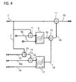
- eine Pulsationskorrektur gemäß einer weiteren Ausgestaltungsform der Erfindung.
- Gleiche oder funktional äquivalente Elemente und Signale sind in allen Figuren mit denselben Bezugszeichen bezeichnet.
-
Figur 1 zeigt in einer stark vereinfachten Darstellung ein Ablaufdiagramm eines Verfahrens zur Pulsationskorrektur eines Ausgangssignals eines Luftmassensensors zur Luftmassenerfassung der Verbrennungsluft einer aufgeladenen Brennkraftmaschine. Das Verfahren umfasst die Verfahrensschritte der Bestimmung eines Luftmassen-Rohsignals aus dem Ausgangssignal des Luftmassensensors (Schritt S1) und des Korrigierens des Luftmassen-Rohsignals auf Pulsationseffekte (Schritt S2). - Die Bestimmung eines Luftmassen-Rohsignals aus dem Ausgangssignal des Luftmassensensors gemäß Schritt S1 ist in
Figur 2 detaillierter dargestellt. Es wurde bereits vorstehend erwähnt, dass die Bestimmung eines Luftmassen-Rohsignals aus dem Ausgangssignal bzw. Rohsignal des Luftmassensensors an sich bereits aus dem Stand der Technik bekannt ist und daher an dieser Stelle nur kurz beschrieben wird. Ein Rohsignal 1 in Form von Strommesswerten eines nach dem Heißfilmprinzip arbeitenden Luftmassensensors (Hitzdraht-Sensor) wird in einem ersten Verarbeitungsschritt abgetastet (gesampled), anschließend mittels einer Konversionskurve 4 linearisiert und dann einer gleitenden Mittelung (engl. sliding window averaging) 5 unterzogen, wobei Segmentinformationen 3 aus dem ersten Verarbeitungsschritt verwendet werden, was durch die gestrichelte Linie dargestellt ist. Das hierdurch erhaltene Signal wird über einen oder mehrere Filter 6 aufbereitet, um ein Luftmassen-Rohsignal 7 zu erhalten. - Es wird betont, dass die vorstehende Beschreibung lediglich beispielhaft eine Bestimmung des Luftmassen-Rohsignals angibt und im Rahmen der Erfindung andere bekannte Ansätze verwendet werden können, um aus den gemessen elektrischen Größen des Luftmassensensors ein Luftmassenrohsignal zu bestimmen.
-
Figur 3 erläutert eine Pulsationskorrektur (Schritt S2) gemäß einer Ausgestaltungsform der Erfindung. - Um die durch eine evtl. auftretende Pulsation im Luftstrom verfälschten Messwerte des Luftmassenrohsignals 7 zu korrigieren, wird ein erster Korrekturfaktor 10 verwendet, der in Abhängigkeit von dem Luftmassen-Rohsignal 7 und von einem Verdichtungsverhältnis 8 eines Verdichters eines Abgasturboladers ermittelt wird. Der erste Korrekturfaktor 10 ist in einem ersten Pulsationskorrekturkennfeld 9 abgelegt, das als erste Eingangsgröße das Luftmassen-Rohsignal 7 und als zweite Eingangsgröße das Verdichtungsverhältnis 8 des Verdichters des Abgasturboladers hat. Aus diesen beiden Eingangsgrößen 7 und 8 ergibt sich der erste Pulsationskorrekturfaktor 10. Dieser wird mit dem Luftmassen-Rohsignal 7 multipliziert und ergibt das auf Pulsationseffekte korrigierte Luftmassensignal 12. Der Pulsationskorrekturfaktor 10 ist somit ein multiplikativer Korrekturfaktor, was durch die mit dem Bezugszeichen 11 gekennzeichnete Multiplikationsoperation dargestellt ist. Das Verdichtungsverhältnis des Verdichters ergibt sich aus dem Verhältnis aus Ansaugdruck vor dem Verdichter und dem Ladeluftdruck nach dem Verdichter und kann aus modellierten oder berechneten Signalen, die den Ansaugdruck vor dem Verdichter und den Ladeluftdruck nach dem Verdichter angeben, berechnet werden.
- Das Pulsationskorrekturkennfeld 9 kann empirisch für verschiedene Brennkraftmaschinen auf einem Prüfstand ermittelt werden, wobei ein mittels eines labortechnischen Messgeräts bestimmtes Referenzluftmassensignal mit dem Luftmassen-Rohsignal 7 für verschieden Betriebszustände, insbesondere verschiedene Verdichtungsverhältnisse, verglichen wird. Aus den ermittelten Vergleichsdaten kann dann das Pulsationskorrekturfeld 9 bestimmt werden.
- In
Figur 4 ist eine Pulsationskorrektur (Schritt S2) gemäß einer weiteren Ausgestaltungsform der Erfindung erläutert. Hierbei wird wiederum der erste Korrekturfaktor 10 verwendet, der in Abhängigkeit von dem aktuellen Luftmassen-Rohsignal 7 und von einem aktuellen Verdichtungsverhältnis 8 eines Verdichters eines Abgasturboladers ermittelt wird. Optional kann das das Luftmassen-Rohsignal 7 mit einem Verdichterkorrekturfaktor 8a multipliziert werden, dessen Wert in Abhängigkeit von einem aktuellen Verdichterbetriebszustand festgelegt wird. Dadurch können Einflüsse des Verdichterbetriebszustands auf die Pulsation berücksichtigt werden, die nicht von dem Verdichtungsverhältnis herrühren. Der erste Korrekturfaktor 10 ist wiederum in dem Pulsationskorrekturkennfeld 9 abgelegt, das als erste Eingangsgröße das Luftmassen-Rohsignal 7 und als zweite Eingangsgröße das Verdichtungsverhältnis 8 des Verdichters des Abgasturboladers hat. - Die Besonderheit dieser Ausführungsvariante liegt darin, dass zur Korrektur des Luftmassen-Rohsignals 7 ein zweiter Korrekturfaktor 18 verwendet wird, der in Abhängigkeit von einem aktuellen Abgasmassenstrom 14 und einem aktuellen Expansionsverhältnis 16 der Turbine des Abgasturboladers ermittelt wird. Hierbei ist der zweite Korrekturfaktor 18 ebenfalls in einem Pulsationskorrekturkennfeld 17 abgelegt ist, das als erste Eingangsgröße den Abgasmassenstrom 14 und als zweite Eingangsgröße das Expansionsverhältnis 16 der Turbine des Abgasturboladers hat. Das Expansionsverhältnis der Turbine des Abgasturboladers ergibt sich aus dem Verhältnis aus Abgasdruck vor der Turbine und dem Auslassdruck der Turbine. Das Pulsationskorrekturkennfeld 17 kann wiederum empirisch für verschiedene Brennkraftmaschinen auf einem Prüfstand, analog wie zuvor für das erste Pulsationskorrekturkennfeld 9 beschrieben, ermittelt werden. Die Variante ermöglicht eine weitere Steigerung der Genauigkeit der Pulsationskorrektur, insbesondere bei der Verwendung von Abgasturboladern mit variabler Turbinengeometrie. Der Abgasmassensignal 14 wird additiv aus dem Luftmassen-Rohsignal 7 und einer aktuellen Kraftstoffeinspritzmenge 13 der Brennkraftmaschine berechnet. Dies ist durch die mit dem Bezugszeichen 21 gekennzeichnete Additions-Verarbeitung gekennzeichnet.
- Optional kann ein Turbinenkorrekturfaktor 16a verwendet werden, der bei einer Turbine mit variabler Turbinengeometrie zur Korrektur des Einflusses des Öffnungszustands der Turbine auf die Pulsation der Verbrennungsluft oder zur Temperaturkorrektur des Abgasmassenstroms verwendet werden kann. Der Korrekturfaktor kann hierfür in Abhängigkeit von einer Temperatur des Abgasmassenstroms vor der Turbine (hierfür kann auch ein Modellwert verwendet werden) und/oder in Abhängigkeit von einem Öffnungszustand einer Turbine des Abgasturboladers, falls die Turbinengeometrie variabel einstellbar ist, festgelegt werden.
- Das Expansionsverhältnis der Turbine des Abgasturboladers ergibt sich aus dem Verhältnis aus Abgasdruck vor der Turbine und dem Auslassdruck der Turbine.
- Die beiden ermittelten Korrekturfaktoren 10 und 18 werden anschließend miteinander multipliziert und der resultierende Gesamtkorrekturfaktor 19 dann mit dem Luftmassen-Rohsignal 7 multipliziert, um das korrigierte Luftmassensignal 20 zu erhalten.
- Wie vorstehend bereits erwähnt, besteht gemäß einer alternativen, nicht dargestellten Ausführungsform die Möglichkeit, das Ausgangssignal 1 direkt in die Pulsationskorrekturkennfelder einzuspeisen. Die Ausgangsgröße aus mindestens einem der Pulsationskennfelder ist dann ein korrigiertes, ungefiltertes Luftmassensignal. Die bekannten Filterungen können anschließend auf das ungefilterte Luftmassensignal angewendet werden.
- Wie vorstehend bereits erwähnt, ermöglicht das vorgeschlagene Pulsationskorrekturverfahren unter Verwendung des Verdichtungsverhältnisses des Verdichters des Abgasturboladers eine besonders genaue und für alle Betriebszustände der Verbrennungskraftmaschine gültige Pulsationskorrektur, so dass auf weitere Korrekturen durch Stellerpositionen etc. verzichtet werden kann. Ein weiterer Vorteil ist, dass dadurch die Genauigkeit des erfindungsgemäßen Korrekturverfahrens über die Lebensdauer der Verbrennungskraftmaschine konstant bleibt.
-
Figur 1 B zeigt eine vereinfachte schematische Darstellung einer Vorrichtung 22 zur Pulsationskorrektur gemäß einer Ausgestaltungsform der Erfindung. Die Vorrichtung kann als eigenständige Korrektureinheit oder als Teil eines Motorsteuergeräts ausgeführt sein. Die Vorrichtung 22 ist eingerichtet, ein Ausgangssignal 1 des Luftmassensensors 24 zu empfangen. Die Vorrichtung ist ferner eingerichtet, über die Eingangssignalleitungen 23, z. B. über den CAN-Datenbus, weitere Parameter und Messwerte zu empfangen, die die zuvor beschriebenen Größen 8, 13, 16 oder Größen, aus denen die Größen 8, 13, 16 berechenbar sind, enthalten. In der Vorrichtung sind ferner die Pulsationskorrekturkennfelder 9 und 17 hinterlegt, und die Vorrichtung ist eingerichtet, die Signalverarbeitung, wie in denFiguren 2 bis 4 beschrieben, zur Pulsationskorrektur durchzuführen. - Die Erfindung ist nicht auf die vorstehend beschriebenen bevorzugten Ausführungsbeispiele beschränkt. Vielmehr ist eine Vielzahl von Varianten und Abwandlungen möglich, die ebenfalls von dem Erfindungsgedanken Gebrauch machen und deshalb in den Schutzbereich fallen. Insbesondere beansprucht die Erfindung auch Schutz für den Gegenstand und die Merkmale der Unteransprüche unabhängig von den in Bezug genommenen Ansprüchen.
-
- 1
- Ausgangssignal Luftmassensensor
- 2
- Abgetastete Rohmesswerte
- 3
- Segmentinformationen
- 4
- Konversionskurve
- 5
- Gleitende Mittelung
- 6
- Filterverarbeitung
- 7
- Luftmassen-Rohsignal
- 8
- Verdichtungsverhältnis
- 8a
- Verdichterkorrekturfaktor
- 9
- Erstes Pulsationskorrekturkennfeld
- 10
- Erster Korrekturfaktor
- 11
- Multiplikationsverarbeitung
- 12
- Korrigiertes Luftmassensignal
- 13
- Kraftstoffeinspritzmenge
- 14
- Abgasmassensignal
- 15
- Korrigiertes Abgasmassensignal
- 16
- Expansionsverhältnis
- 16a
- Turbinenkorrekturfaktor
- 17
- Zweites Pulsationskorrekturkennfeld
- 18
- Zweiter Korrekturfaktor
- 19
- Korrekturfaktor
- 20
- Korrigiertes Luftmassensignal
- 21
- Additive Verarbeitung
- 22
- Vorrichtung zur Pulsationskorrektur
- 23
- Eingangssignale
- 24
- Luftmassensensor
Claims (11)
- Verfahren zur Pulsationskorrektur eines Ausgangssignals (1) eines Luftmassensensors (24) zur Luftmassenerfassung der Verbrennungsluft einer aufgeladenen Brennkraftmaschine, dadurch gekennzeichnet, dass zur Korrektur des Ausgangssignals (1) des Luftmassensensors (24) auf Pulsationseffekte ein erster Korrekturfaktor (10) verwendet wird, der in Abhängigkeit von einem Verdichtungsverhältnis (8) eines Verdichters eines Abgasturboladers ermittelt wird.
- Verfahren nach Anspruch 1, dadurch gekennzeichnet, dass zur Korrektur des Luftmassen-Rohsignals (7) ein zweiter Korrekturfaktor (18) verwendet wird, der in Abhängigkeit von einem Expansionsverhältnis (16) einer Turbine des Abgasturboladers ermittelt wird.
- Verfahren nach Anspruch 1 oder 2, dadurch gekennzeichnet,(a) dass zur Pulsationskorrektur des Ausgangssignals (1) des Luftmassensensors (24) ein Luftmassen-Rohsignal (7) aus dem Ausgangssignal (1) des Luftmassensensors (S1) bestimmt wird (S1) und anschließend das bestimmte Luftmassen-Rohsignal auf Pulsationseffekte unter Verwendung des ersten Korrekturfaktors korrigiert wird (S2); und(b) dass der erste Korrekturfaktor (10) in Abhängigkeit von dem Luftmassen-Rohsignal (7) und von dem Verdichtungsverhältnis (8) des Verdichters ermittelt wird und in einem ersten Pulsationskorrekturkennfeld (9) abgelegt ist, das als erste Eingangsgröße das Luftmassen-Rohsignal (7) und als zweite Eingangsgröße das Verdichtungsverhältnis (8) des Verdichters hat.
- Verfahren nach Anspruch 3, wenn abhängig von Anspruch 2, dadurch gekennzeichnet, dass der zweite Korrekturfaktor (18) in Abhängigkeit von einem Abgasmassenstrom (14) und einem Expansionsverhältnis (16) der Turbine des Abgasturboladers ermittelt wird und in einem zweiten Pulsationskorrekturkennfeld (17) abgelegt ist, das als erste Eingangsgröße den Abgasmassenstrom (14) und als zweite Eingangsgröße das Expansionsverhältnis (16) der Turbine des Abgasturboladers hat.
- Verfahren nach Anspruch 4, dadurch gekennzeichnet, dass der Abgasmassenstrom (14) aus dem Luftmassen-Rohsignal (7) und einer aktuellen Kraftstoffeinspritzmenge (13) der Brennkraftmaschine berechnet wird.
- Verfahren nach Anspruch 1 oder 2, dadurch gekennzeichnet,(a) dass zur Pulsationskorrektur das Ausgangssignals (1) des Luftmassensensors (24) unter Verwendung des ersten Korrekturfaktors korrigiert wird (S2) und das korrigierte Ausgangssignal anschließend in ein Luftmassen-Rohsignal umgewandelt wird; und(b) dass der erste Korrekturfaktor in einem dritten Pulsationskorrekturkennfeld abgelegt ist, das als erste Eingangsgröße das elektrische Ausgangssignal des Luftmassensensors (23) und als zweite Eingangsgröße das Verdichtungsverhältnis (8) des Verdichters des Abgasturboladers hat.
- Verfahren nach einem der vorherigen Ansprüche, dadurch gekennzeichnet, dass der erste Korrekturfaktor (10) ein multiplikativer Korrekturfaktor ist.
- Verfahren nach einem der Ansprüche 2 bis 7, dadurch gekennzeichnet, dass der zweite Korrekturfaktor (18) ein multiplikativer Korrekturfaktor ist.
- Verfahren nach einem der vorherigen Ansprüche, dadurch gekennzeichnet, dass zur Pulsationskorrektur(a) ein Verdichterkorrekturfaktor (8a) verwendet wird, dessen Wert in Abhängigkeit von einem aktuellen Verdichterbetriebszustand festgelegt wird, um Einflüsse des Verdichterbetriebszustands auf die Pulsation zu berücksichtigten, die nicht von dem Verdichtungsverhältnis herrühren; und/oder(b) ein Turbinenkorrekturfaktor (16a) verwendet wird, dessen Wert in Abhängigkeit von einer Temperatur des Abgasmassenstroms und/oder in Abhängigkeit von einem Öffnungszustand einer Turbine des Abgasturboladers, falls die Turbinengeometrie variabel einstellbar ist, festgelegt wird.
- Vorrichtung (22) zur Pulsationskorrektur eines Ausgangssignals (1) eines Luftmassensensors (24) zur Luftmassenerfassung der Verbrennungsluft einer aufgeladenen Brennkraftmaschine, wobei die Vorrichtung (22) eingerichtet ist, ein Ausgangssignal (1) des Luftmassensensors zu empfangen, dadurch gekennzeichnet, dass die Vorrichtung zur Korrektur des Ausgangssignals (1) auf Pulsationseffekte eingerichtet ist, das Verfahren gemäß einem der Ansprüche 1 bis 9 durchzuführen.
- Kraftfahrzeug, insbesondere Nutzfahrzeug, aufweisend eine aufgeladene Brennkraftmaschine und eine Vorrichtung (22) nach Anspruch 10.
Applications Claiming Priority (1)
| Application Number | Priority Date | Filing Date | Title |
|---|---|---|---|
| DE102014016782.8A DE102014016782A1 (de) | 2014-11-13 | 2014-11-13 | Verfahren und Vorrichtung zur Pulsationskorrektur eines Ausgangssignals eines Luftmassensensors |
Publications (2)
| Publication Number | Publication Date |
|---|---|
| EP3029302A1 true EP3029302A1 (de) | 2016-06-08 |
| EP3029302B1 EP3029302B1 (de) | 2017-10-11 |
Family
ID=53836348
Family Applications (1)
| Application Number | Title | Priority Date | Filing Date |
|---|---|---|---|
| EP15002294.5A Active EP3029302B1 (de) | 2014-11-13 | 2015-08-01 | Verfahren und vorrichtung zur pulsationskorrektur eines ausgangssignals eines luftmassensensors |
Country Status (5)
| Country | Link |
|---|---|
| EP (1) | EP3029302B1 (de) |
| CN (1) | CN105604714B (de) |
| BR (1) | BR102015020846B1 (de) |
| DE (1) | DE102014016782A1 (de) |
| RU (1) | RU2702207C2 (de) |
Citations (6)
| Publication number | Priority date | Publication date | Assignee | Title |
|---|---|---|---|---|
| JPS56107124A (en) | 1980-01-30 | 1981-08-25 | Hitachi Ltd | Processing method for signal of hot-wire flow-rate sensor |
| DE3344276A1 (de) | 1982-12-07 | 1984-06-07 | Nippondenso Co., Ltd., Kariya, Aichi | Verfahren zur korrektur einer gesteuerten bzw. geregelten variablen zur steuerung bzw. regelung des luft-brennstoffverhaeltnisses oder des zuendzeitpunktes eines verbrennungsmotors |
| US5191789A (en) * | 1990-11-27 | 1993-03-09 | Japan Electronic Control Systems Co., Ltd. | Method and system for detecting intake air flow rate in internal combustion engine coupled with supercharger |
| FR2854435A1 (fr) * | 2003-04-30 | 2004-11-05 | Bosch Gmbh Robert | Procede et dispositif de gestion d'un moteur a combustion interne |
| JP2006226122A (ja) * | 2005-02-15 | 2006-08-31 | Nissan Diesel Motor Co Ltd | 吸気流量測定装置及び吸気流量測定方法 |
| EP2703626A2 (de) * | 2012-08-28 | 2014-03-05 | Kabushiki Kaisha Toyota Jidoshokki | Steuerverfahren und Steuervorrichtungen für Verbrennungsmotoren |
Family Cites Families (11)
| Publication number | Priority date | Publication date | Assignee | Title |
|---|---|---|---|---|
| JP2528385B2 (ja) * | 1990-11-27 | 1996-08-28 | 株式会社ユニシアジェックス | 過給機付内燃機関の吸入空気量検出装置 |
| JP2622625B2 (ja) * | 1991-02-06 | 1997-06-18 | 株式会社ユニシアジェックス | 内燃機関の吸入空気流量検出装置及び燃料供給制御装置 |
| DE19963358A1 (de) * | 1999-12-28 | 2001-07-12 | Bosch Gmbh Robert | Verfahren und Vorrichtung zur Steuerung einer Brennkraftmaschine mit einem Luftsystem |
| JP3835152B2 (ja) * | 2000-10-05 | 2006-10-18 | 日産自動車株式会社 | 過給機の制御装置 |
| DE10232337B4 (de) * | 2002-07-17 | 2017-05-11 | Robert Bosch Gmbh | Verfahren und Vorrichtung zur Überwachung einer Luftmassenmessvorrichtung |
| JP4595701B2 (ja) * | 2005-06-21 | 2010-12-08 | トヨタ自動車株式会社 | 電動機付き過給機を有する内燃機関の制御装置 |
| JP4254761B2 (ja) * | 2005-08-22 | 2009-04-15 | トヨタ自動車株式会社 | 過給器付き内燃機関の制御装置 |
| JP4782759B2 (ja) * | 2007-10-24 | 2011-09-28 | 株式会社デンソー | 内燃機関制御装置および内燃機関制御システム |
| FR2943727A1 (fr) * | 2009-03-30 | 2010-10-01 | Renault Sas | Procede, pour un turbocompresseur de suralimemntation, de determination d'une consigne de position d'un actionneur de by-pass. |
| EP2615274A4 (de) * | 2010-09-06 | 2015-07-08 | Toyota Motor Co Ltd | Steuerungsvorrichtung für einen verbrennungsmotor |
| US20140326213A1 (en) * | 2011-12-07 | 2014-11-06 | Toyota Jidosha Kabushiki Kaisha | Control device for supercharged engine |
-
2014
- 2014-11-13 DE DE102014016782.8A patent/DE102014016782A1/de not_active Withdrawn
-
2015
- 2015-08-01 EP EP15002294.5A patent/EP3029302B1/de active Active
- 2015-08-20 BR BR102015020846-4A patent/BR102015020846B1/pt active IP Right Grant
- 2015-09-28 RU RU2015141281A patent/RU2702207C2/ru active
- 2015-11-13 CN CN201510773694.7A patent/CN105604714B/zh active Active
Patent Citations (6)
| Publication number | Priority date | Publication date | Assignee | Title |
|---|---|---|---|---|
| JPS56107124A (en) | 1980-01-30 | 1981-08-25 | Hitachi Ltd | Processing method for signal of hot-wire flow-rate sensor |
| DE3344276A1 (de) | 1982-12-07 | 1984-06-07 | Nippondenso Co., Ltd., Kariya, Aichi | Verfahren zur korrektur einer gesteuerten bzw. geregelten variablen zur steuerung bzw. regelung des luft-brennstoffverhaeltnisses oder des zuendzeitpunktes eines verbrennungsmotors |
| US5191789A (en) * | 1990-11-27 | 1993-03-09 | Japan Electronic Control Systems Co., Ltd. | Method and system for detecting intake air flow rate in internal combustion engine coupled with supercharger |
| FR2854435A1 (fr) * | 2003-04-30 | 2004-11-05 | Bosch Gmbh Robert | Procede et dispositif de gestion d'un moteur a combustion interne |
| JP2006226122A (ja) * | 2005-02-15 | 2006-08-31 | Nissan Diesel Motor Co Ltd | 吸気流量測定装置及び吸気流量測定方法 |
| EP2703626A2 (de) * | 2012-08-28 | 2014-03-05 | Kabushiki Kaisha Toyota Jidoshokki | Steuerverfahren und Steuervorrichtungen für Verbrennungsmotoren |
Also Published As
| Publication number | Publication date |
|---|---|
| RU2702207C2 (ru) | 2019-10-04 |
| RU2015141281A3 (de) | 2019-03-01 |
| CN105604714A (zh) | 2016-05-25 |
| BR102015020846B1 (pt) | 2022-07-12 |
| RU2015141281A (ru) | 2017-04-03 |
| EP3029302B1 (de) | 2017-10-11 |
| CN105604714B (zh) | 2020-08-04 |
| BR102015020846A2 (pt) | 2018-03-06 |
| DE102014016782A1 (de) | 2016-05-19 |
Similar Documents
| Publication | Publication Date | Title |
|---|---|---|
| DE10310221B4 (de) | Verfahren zur Begrenzung eines Ladedrucks | |
| DE102014201947B3 (de) | Verfahren und Vorrichtung zur Bestimmung eines Ladeluftmassenstroms | |
| DE102014217591B4 (de) | Verfahren und Vorrichtung zur Ansteuerung eines Abgasrückführventils einer aufgeladenen Brennkraftmaschine mit Abgasrückführung | |
| EP2791493A1 (de) | Verfahren und vorrichtung zur dynamiküberwachung von gas-sensoren | |
| WO2009074400A2 (de) | Verfahren zur bestimmung von adaptierten messwerten und/oder modellparametern zur steuerung des luftpfads von verbrennungsmotoren | |
| EP1272753B1 (de) | Verfahren und vorrichtung zur steuerung einer brennkraftmaschine | |
| EP1623103B1 (de) | Verfahren zur drehzahl überwachung eines bi-turboladers | |
| EP1402240B1 (de) | Verfahren und vorrichtung zur ermittlung einer temperaturgrösse in einer massenstromleitung | |
| EP0197315A2 (de) | Vorrichtung für eine Brennkraftmaschine zur Beeinflussung von Betriebsparametern | |
| EP1999352A1 (de) | Verfahren und vorrichtung zur regelung oder steuerung eines verdichters eines abgas-turboladers | |
| DE102004038733A1 (de) | Verfahren und Vorrichtung zum Betreiben einer Brennkraftmaschine | |
| DE102005004319A1 (de) | Bestimmung des Luftmassenstroms in Kraftfahrzeugen | |
| DE102013209551A1 (de) | Verfahren und Steuereinheit zur Bestimmung eines Massenstroms in einer Hochdruck-Abgas-Rückführung einer Brennkraftmaschine | |
| DE102007012340B3 (de) | Verfahren zum Ermitteln und Einregeln des Luftmassenstroms im Saugrohr eines Verbrennungsmotors sowie zugehöriges Steuergerät | |
| EP3029302B1 (de) | Verfahren und vorrichtung zur pulsationskorrektur eines ausgangssignals eines luftmassensensors | |
| DE19525815B4 (de) | Verfahren zur Erfassung des Lastsignals einer Brennkraftmaschine | |
| EP1609970B1 (de) | Verfahren und Vorrichtung zum Betreiben einer Brennkraftmaschine | |
| DE10160469A1 (de) | Verfahren zur Begrenzung der Drehzahl eines Abgasturboladers für eine Brennkraftmaschine | |
| EP1296029B1 (de) | Verfahren und Vorrichtung zur Steuerung einer Brennkraftmaschine | |
| DE102006022383B4 (de) | Verfahren zur Signalauswertung eines Partikelsensors | |
| DE102016012019A1 (de) | Verfahren zum Ermitteln von Verbrennungsaussetzern einer Verbrennungskraftmaschine | |
| DE102017221624B3 (de) | Verfahren zum Abgleich einer von einem Luftmassensensor eines Verbrennungsmotors erfassten Messgröße sowie Steuereinrichtung zum Durchführen eines solchen Verfahrens | |
| DE102008005800B4 (de) | Verfahren und Vorrichtung zur Ladedruckbegrenzung in einem mit einem Turboladersystem ausgestatteten Verbrennungsmotor | |
| DE102016225739B3 (de) | Verfahren und Vorrichtung zum Bestimmen eines Luftmassenstromes in einem Verbrennungsmotor | |
| DE102017219175A1 (de) | Verfahren zur Bestimmung einer Zylinderfüllung einer Brennkraftmaschine mit einer variablen Ventilhubeinrichtung |
Legal Events
| Date | Code | Title | Description |
|---|---|---|---|
| PUAI | Public reference made under article 153(3) epc to a published international application that has entered the european phase |
Free format text: ORIGINAL CODE: 0009012 |
|
| AK | Designated contracting states |
Kind code of ref document: A1 Designated state(s): AL AT BE BG CH CY CZ DE DK EE ES FI FR GB GR HR HU IE IS IT LI LT LU LV MC MK MT NL NO PL PT RO RS SE SI SK SM TR |
|
| AX | Request for extension of the european patent |
Extension state: BA ME |
|
| STAA | Information on the status of an ep patent application or granted ep patent |
Free format text: STATUS: REQUEST FOR EXAMINATION WAS MADE |
|
| 17P | Request for examination filed |
Effective date: 20161107 |
|
| GRAP | Despatch of communication of intention to grant a patent |
Free format text: ORIGINAL CODE: EPIDOSNIGR1 |
|
| STAA | Information on the status of an ep patent application or granted ep patent |
Free format text: STATUS: GRANT OF PATENT IS INTENDED |
|
| RIC1 | Information provided on ipc code assigned before grant |
Ipc: F02D 41/00 20060101ALI20170131BHEP Ipc: G01F 15/02 20060101ALI20170131BHEP Ipc: G01F 1/696 20060101ALN20170131BHEP Ipc: F02D 41/18 20060101AFI20170131BHEP Ipc: G01F 1/72 20060101ALI20170131BHEP |
|
| INTG | Intention to grant announced |
Effective date: 20170223 |
|
| RIC1 | Information provided on ipc code assigned before grant |
Ipc: F02D 41/00 20060101ALI20170214BHEP Ipc: G01F 15/02 20060101ALI20170214BHEP Ipc: G01F 1/72 20060101ALI20170214BHEP Ipc: G01F 1/696 20060101ALN20170214BHEP Ipc: F02D 41/18 20060101AFI20170214BHEP |
|
| GRAS | Grant fee paid |
Free format text: ORIGINAL CODE: EPIDOSNIGR3 |
|
| GRAJ | Information related to disapproval of communication of intention to grant by the applicant or resumption of examination proceedings by the epo deleted |
Free format text: ORIGINAL CODE: EPIDOSDIGR1 |
|
| GRAL | Information related to payment of fee for publishing/printing deleted |
Free format text: ORIGINAL CODE: EPIDOSDIGR3 |
|
| STAA | Information on the status of an ep patent application or granted ep patent |
Free format text: STATUS: REQUEST FOR EXAMINATION WAS MADE |
|
| INTC | Intention to grant announced (deleted) | ||
| RIC1 | Information provided on ipc code assigned before grant |
Ipc: F02D 41/00 20060101ALI20170711BHEP Ipc: G01F 1/696 20060101ALN20170711BHEP Ipc: G01F 1/72 20060101ALI20170711BHEP Ipc: F02D 41/18 20060101AFI20170711BHEP Ipc: G01F 15/02 20060101ALI20170711BHEP |
|
| GRAR | Information related to intention to grant a patent recorded |
Free format text: ORIGINAL CODE: EPIDOSNIGR71 |
|
| STAA | Information on the status of an ep patent application or granted ep patent |
Free format text: STATUS: GRANT OF PATENT IS INTENDED |
|
| GRAA | (expected) grant |
Free format text: ORIGINAL CODE: 0009210 |
|
| STAA | Information on the status of an ep patent application or granted ep patent |
Free format text: STATUS: THE PATENT HAS BEEN GRANTED |
|
| INTG | Intention to grant announced |
Effective date: 20170830 |
|
| AK | Designated contracting states |
Kind code of ref document: B1 Designated state(s): AL AT BE BG CH CY CZ DE DK EE ES FI FR GB GR HR HU IE IS IT LI LT LU LV MC MK MT NL NO PL PT RO RS SE SI SK SM TR |
|
| REG | Reference to a national code |
Ref country code: GB Ref legal event code: FG4D Free format text: NOT ENGLISH |
|
| REG | Reference to a national code |
Ref country code: CH Ref legal event code: EP |
|
| REG | Reference to a national code |
Ref country code: IE Ref legal event code: FG4D Free format text: LANGUAGE OF EP DOCUMENT: GERMAN |
|
| REG | Reference to a national code |
Ref country code: AT Ref legal event code: REF Ref document number: 936277 Country of ref document: AT Kind code of ref document: T Effective date: 20171115 |
|
| REG | Reference to a national code |
Ref country code: NL Ref legal event code: FP |
|
| REG | Reference to a national code |
Ref country code: DE Ref legal event code: R096 Ref document number: 502015002033 Country of ref document: DE |
|
| REG | Reference to a national code |
Ref country code: SE Ref legal event code: TRGR |
|
| REG | Reference to a national code |
Ref country code: LT Ref legal event code: MG4D |
|
| PG25 | Lapsed in a contracting state [announced via postgrant information from national office to epo] |
Ref country code: ES Free format text: LAPSE BECAUSE OF FAILURE TO SUBMIT A TRANSLATION OF THE DESCRIPTION OR TO PAY THE FEE WITHIN THE PRESCRIBED TIME-LIMIT Effective date: 20171011 Ref country code: FI Free format text: LAPSE BECAUSE OF FAILURE TO SUBMIT A TRANSLATION OF THE DESCRIPTION OR TO PAY THE FEE WITHIN THE PRESCRIBED TIME-LIMIT Effective date: 20171011 Ref country code: NO Free format text: LAPSE BECAUSE OF FAILURE TO SUBMIT A TRANSLATION OF THE DESCRIPTION OR TO PAY THE FEE WITHIN THE PRESCRIBED TIME-LIMIT Effective date: 20180111 Ref country code: LT Free format text: LAPSE BECAUSE OF FAILURE TO SUBMIT A TRANSLATION OF THE DESCRIPTION OR TO PAY THE FEE WITHIN THE PRESCRIBED TIME-LIMIT Effective date: 20171011 |
|
| PG25 | Lapsed in a contracting state [announced via postgrant information from national office to epo] |
Ref country code: IS Free format text: LAPSE BECAUSE OF FAILURE TO SUBMIT A TRANSLATION OF THE DESCRIPTION OR TO PAY THE FEE WITHIN THE PRESCRIBED TIME-LIMIT Effective date: 20180211 Ref country code: HR Free format text: LAPSE BECAUSE OF FAILURE TO SUBMIT A TRANSLATION OF THE DESCRIPTION OR TO PAY THE FEE WITHIN THE PRESCRIBED TIME-LIMIT Effective date: 20171011 Ref country code: GR Free format text: LAPSE BECAUSE OF FAILURE TO SUBMIT A TRANSLATION OF THE DESCRIPTION OR TO PAY THE FEE WITHIN THE PRESCRIBED TIME-LIMIT Effective date: 20180112 Ref country code: RS Free format text: LAPSE BECAUSE OF FAILURE TO SUBMIT A TRANSLATION OF THE DESCRIPTION OR TO PAY THE FEE WITHIN THE PRESCRIBED TIME-LIMIT Effective date: 20171011 Ref country code: BG Free format text: LAPSE BECAUSE OF FAILURE TO SUBMIT A TRANSLATION OF THE DESCRIPTION OR TO PAY THE FEE WITHIN THE PRESCRIBED TIME-LIMIT Effective date: 20180111 Ref country code: LV Free format text: LAPSE BECAUSE OF FAILURE TO SUBMIT A TRANSLATION OF THE DESCRIPTION OR TO PAY THE FEE WITHIN THE PRESCRIBED TIME-LIMIT Effective date: 20171011 |
|
| REG | Reference to a national code |
Ref country code: DE Ref legal event code: R097 Ref document number: 502015002033 Country of ref document: DE |
|
| PG25 | Lapsed in a contracting state [announced via postgrant information from national office to epo] |
Ref country code: DK Free format text: LAPSE BECAUSE OF FAILURE TO SUBMIT A TRANSLATION OF THE DESCRIPTION OR TO PAY THE FEE WITHIN THE PRESCRIBED TIME-LIMIT Effective date: 20171011 Ref country code: EE Free format text: LAPSE BECAUSE OF FAILURE TO SUBMIT A TRANSLATION OF THE DESCRIPTION OR TO PAY THE FEE WITHIN THE PRESCRIBED TIME-LIMIT Effective date: 20171011 Ref country code: SK Free format text: LAPSE BECAUSE OF FAILURE TO SUBMIT A TRANSLATION OF THE DESCRIPTION OR TO PAY THE FEE WITHIN THE PRESCRIBED TIME-LIMIT Effective date: 20171011 Ref country code: CZ Free format text: LAPSE BECAUSE OF FAILURE TO SUBMIT A TRANSLATION OF THE DESCRIPTION OR TO PAY THE FEE WITHIN THE PRESCRIBED TIME-LIMIT Effective date: 20171011 |
|
| PLBE | No opposition filed within time limit |
Free format text: ORIGINAL CODE: 0009261 |
|
| STAA | Information on the status of an ep patent application or granted ep patent |
Free format text: STATUS: NO OPPOSITION FILED WITHIN TIME LIMIT |
|
| REG | Reference to a national code |
Ref country code: FR Ref legal event code: PLFP Year of fee payment: 4 |
|
| PG25 | Lapsed in a contracting state [announced via postgrant information from national office to epo] |
Ref country code: SM Free format text: LAPSE BECAUSE OF FAILURE TO SUBMIT A TRANSLATION OF THE DESCRIPTION OR TO PAY THE FEE WITHIN THE PRESCRIBED TIME-LIMIT Effective date: 20171011 Ref country code: PL Free format text: LAPSE BECAUSE OF FAILURE TO SUBMIT A TRANSLATION OF THE DESCRIPTION OR TO PAY THE FEE WITHIN THE PRESCRIBED TIME-LIMIT Effective date: 20171011 Ref country code: RO Free format text: LAPSE BECAUSE OF FAILURE TO SUBMIT A TRANSLATION OF THE DESCRIPTION OR TO PAY THE FEE WITHIN THE PRESCRIBED TIME-LIMIT Effective date: 20171011 |
|
| 26N | No opposition filed |
Effective date: 20180712 |
|
| PG25 | Lapsed in a contracting state [announced via postgrant information from national office to epo] |
Ref country code: MT Free format text: LAPSE BECAUSE OF FAILURE TO SUBMIT A TRANSLATION OF THE DESCRIPTION OR TO PAY THE FEE WITHIN THE PRESCRIBED TIME-LIMIT Effective date: 20171011 |
|
| PG25 | Lapsed in a contracting state [announced via postgrant information from national office to epo] |
Ref country code: SI Free format text: LAPSE BECAUSE OF FAILURE TO SUBMIT A TRANSLATION OF THE DESCRIPTION OR TO PAY THE FEE WITHIN THE PRESCRIBED TIME-LIMIT Effective date: 20171011 |
|
| PG25 | Lapsed in a contracting state [announced via postgrant information from national office to epo] |
Ref country code: MC Free format text: LAPSE BECAUSE OF FAILURE TO SUBMIT A TRANSLATION OF THE DESCRIPTION OR TO PAY THE FEE WITHIN THE PRESCRIBED TIME-LIMIT Effective date: 20171011 |
|
| REG | Reference to a national code |
Ref country code: CH Ref legal event code: PL |
|
| PG25 | Lapsed in a contracting state [announced via postgrant information from national office to epo] |
Ref country code: CH Free format text: LAPSE BECAUSE OF NON-PAYMENT OF DUE FEES Effective date: 20180831 Ref country code: LU Free format text: LAPSE BECAUSE OF NON-PAYMENT OF DUE FEES Effective date: 20180801 Ref country code: LI Free format text: LAPSE BECAUSE OF NON-PAYMENT OF DUE FEES Effective date: 20180831 |
|
| REG | Reference to a national code |
Ref country code: BE Ref legal event code: MM Effective date: 20180831 |
|
| REG | Reference to a national code |
Ref country code: IE Ref legal event code: MM4A |
|
| PG25 | Lapsed in a contracting state [announced via postgrant information from national office to epo] |
Ref country code: IE Free format text: LAPSE BECAUSE OF NON-PAYMENT OF DUE FEES Effective date: 20180801 |
|
| PG25 | Lapsed in a contracting state [announced via postgrant information from national office to epo] |
Ref country code: BE Free format text: LAPSE BECAUSE OF NON-PAYMENT OF DUE FEES Effective date: 20180831 |
|
| REG | Reference to a national code |
Ref country code: DE Ref legal event code: R081 Ref document number: 502015002033 Country of ref document: DE Owner name: MAN TRUCK & BUS SE, DE Free format text: FORMER OWNER: MAN TRUCK & BUS AG, 80995 MUENCHEN, DE |
|
| PG25 | Lapsed in a contracting state [announced via postgrant information from national office to epo] |
Ref country code: TR Free format text: LAPSE BECAUSE OF FAILURE TO SUBMIT A TRANSLATION OF THE DESCRIPTION OR TO PAY THE FEE WITHIN THE PRESCRIBED TIME-LIMIT Effective date: 20171011 |
|
| GBPC | Gb: european patent ceased through non-payment of renewal fee |
Effective date: 20190801 |
|
| PG25 | Lapsed in a contracting state [announced via postgrant information from national office to epo] |
Ref country code: PT Free format text: LAPSE BECAUSE OF FAILURE TO SUBMIT A TRANSLATION OF THE DESCRIPTION OR TO PAY THE FEE WITHIN THE PRESCRIBED TIME-LIMIT Effective date: 20171011 |
|
| PG25 | Lapsed in a contracting state [announced via postgrant information from national office to epo] |
Ref country code: CY Free format text: LAPSE BECAUSE OF FAILURE TO SUBMIT A TRANSLATION OF THE DESCRIPTION OR TO PAY THE FEE WITHIN THE PRESCRIBED TIME-LIMIT Effective date: 20171011 Ref country code: MK Free format text: LAPSE BECAUSE OF NON-PAYMENT OF DUE FEES Effective date: 20171011 Ref country code: HU Free format text: LAPSE BECAUSE OF FAILURE TO SUBMIT A TRANSLATION OF THE DESCRIPTION OR TO PAY THE FEE WITHIN THE PRESCRIBED TIME-LIMIT; INVALID AB INITIO Effective date: 20150801 |
|
| PG25 | Lapsed in a contracting state [announced via postgrant information from national office to epo] |
Ref country code: AL Free format text: LAPSE BECAUSE OF FAILURE TO SUBMIT A TRANSLATION OF THE DESCRIPTION OR TO PAY THE FEE WITHIN THE PRESCRIBED TIME-LIMIT Effective date: 20171011 |
|
| PG25 | Lapsed in a contracting state [announced via postgrant information from national office to epo] |
Ref country code: GB Free format text: LAPSE BECAUSE OF NON-PAYMENT OF DUE FEES Effective date: 20190801 |
|
| REG | Reference to a national code |
Ref country code: AT Ref legal event code: MM01 Ref document number: 936277 Country of ref document: AT Kind code of ref document: T Effective date: 20200801 |
|
| PG25 | Lapsed in a contracting state [announced via postgrant information from national office to epo] |
Ref country code: AT Free format text: LAPSE BECAUSE OF NON-PAYMENT OF DUE FEES Effective date: 20200801 |
|
| PGFP | Annual fee paid to national office [announced via postgrant information from national office to epo] |
Ref country code: NL Payment date: 20250825 Year of fee payment: 11 |
|
| PGFP | Annual fee paid to national office [announced via postgrant information from national office to epo] |
Ref country code: DE Payment date: 20250827 Year of fee payment: 11 |
|
| PGFP | Annual fee paid to national office [announced via postgrant information from national office to epo] |
Ref country code: IT Payment date: 20250825 Year of fee payment: 11 |
|
| PGFP | Annual fee paid to national office [announced via postgrant information from national office to epo] |
Ref country code: FR Payment date: 20250825 Year of fee payment: 11 |
|
| PGFP | Annual fee paid to national office [announced via postgrant information from national office to epo] |
Ref country code: SE Payment date: 20250825 Year of fee payment: 11 |