EP3028974A1 - Vibrating tray for diverted card inserts - Google Patents
Vibrating tray for diverted card inserts Download PDFInfo
- Publication number
- EP3028974A1 EP3028974A1 EP15193620.0A EP15193620A EP3028974A1 EP 3028974 A1 EP3028974 A1 EP 3028974A1 EP 15193620 A EP15193620 A EP 15193620A EP 3028974 A1 EP3028974 A1 EP 3028974A1
- Authority
- EP
- European Patent Office
- Prior art keywords
- tray
- card
- roller
- moving belt
- cards
- Prior art date
- Legal status (The legal status is an assumption and is not a legal conclusion. Google has not performed a legal analysis and makes no representation as to the accuracy of the status listed.)
- Granted
Links
- 238000000034 method Methods 0.000 claims abstract description 9
- 238000006073 displacement reaction Methods 0.000 claims abstract description 5
- 238000000151 deposition Methods 0.000 claims description 4
- 238000002955 isolation Methods 0.000 claims description 4
- 230000032258 transport Effects 0.000 claims description 3
- 230000000284 resting effect Effects 0.000 claims 3
- 239000000463 material Substances 0.000 description 4
- 239000000853 adhesive Substances 0.000 description 2
- 230000001070 adhesive effect Effects 0.000 description 2
- 238000004519 manufacturing process Methods 0.000 description 2
- 208000027418 Wounds and injury Diseases 0.000 description 1
- 239000011358 absorbing material Substances 0.000 description 1
- 230000006378 damage Effects 0.000 description 1
- 230000002950 deficient Effects 0.000 description 1
- 239000013536 elastomeric material Substances 0.000 description 1
- 208000014674 injury Diseases 0.000 description 1
- 238000003780 insertion Methods 0.000 description 1
- 230000037431 insertion Effects 0.000 description 1
- 238000009434 installation Methods 0.000 description 1
- 238000012545 processing Methods 0.000 description 1
- 230000001681 protective effect Effects 0.000 description 1
- 239000002994 raw material Substances 0.000 description 1
- 238000012546 transfer Methods 0.000 description 1
- 238000011144 upstream manufacturing Methods 0.000 description 1
Images

Classifications
-
- B—PERFORMING OPERATIONS; TRANSPORTING
- B65—CONVEYING; PACKING; STORING; HANDLING THIN OR FILAMENTARY MATERIAL
- B65G—TRANSPORT OR STORAGE DEVICES, e.g. CONVEYORS FOR LOADING OR TIPPING, SHOP CONVEYOR SYSTEMS OR PNEUMATIC TUBE CONVEYORS
- B65G27/00—Jigging conveyors
- B65G27/04—Load carriers other than helical or spiral channels or conduits
-
- B—PERFORMING OPERATIONS; TRANSPORTING
- B07—SEPARATING SOLIDS FROM SOLIDS; SORTING
- B07C—POSTAL SORTING; SORTING INDIVIDUAL ARTICLES, OR BULK MATERIAL FIT TO BE SORTED PIECE-MEAL, e.g. BY PICKING
- B07C5/00—Sorting according to a characteristic or feature of the articles or material being sorted, e.g. by control effected by devices which detect or measure such characteristic or feature; Sorting by manually actuated devices, e.g. switches
- B07C5/36—Sorting apparatus characterised by the means used for distribution
-
- B—PERFORMING OPERATIONS; TRANSPORTING
- B65—CONVEYING; PACKING; STORING; HANDLING THIN OR FILAMENTARY MATERIAL
- B65G—TRANSPORT OR STORAGE DEVICES, e.g. CONVEYORS FOR LOADING OR TIPPING, SHOP CONVEYOR SYSTEMS OR PNEUMATIC TUBE CONVEYORS
- B65G27/00—Jigging conveyors
- B65G27/08—Supports or mountings for load-carriers, e.g. framework, bases, spring arrangements
-
- B—PERFORMING OPERATIONS; TRANSPORTING
- B65—CONVEYING; PACKING; STORING; HANDLING THIN OR FILAMENTARY MATERIAL
- B65G—TRANSPORT OR STORAGE DEVICES, e.g. CONVEYORS FOR LOADING OR TIPPING, SHOP CONVEYOR SYSTEMS OR PNEUMATIC TUBE CONVEYORS
- B65G27/00—Jigging conveyors
- B65G27/10—Applications of devices for generating or transmitting jigging movements
- B65G27/16—Applications of devices for generating or transmitting jigging movements of vibrators, i.e. devices for producing movements of high frequency and small amplitude
- B65G27/18—Mechanical devices
-
- B—PERFORMING OPERATIONS; TRANSPORTING
- B65—CONVEYING; PACKING; STORING; HANDLING THIN OR FILAMENTARY MATERIAL
- B65H—HANDLING THIN OR FILAMENTARY MATERIAL, e.g. SHEETS, WEBS, CABLES
- B65H29/00—Delivering or advancing articles from machines; Advancing articles to or into piles
- B65H29/52—Stationary guides or smoothers
-
- B—PERFORMING OPERATIONS; TRANSPORTING
- B65—CONVEYING; PACKING; STORING; HANDLING THIN OR FILAMENTARY MATERIAL
- B65H—HANDLING THIN OR FILAMENTARY MATERIAL, e.g. SHEETS, WEBS, CABLES
- B65H29/00—Delivering or advancing articles from machines; Advancing articles to or into piles
- B65H29/58—Article switches or diverters
- B65H29/62—Article switches or diverters diverting faulty articles from the main streams
-
- B—PERFORMING OPERATIONS; TRANSPORTING
- B65—CONVEYING; PACKING; STORING; HANDLING THIN OR FILAMENTARY MATERIAL
- B65H—HANDLING THIN OR FILAMENTARY MATERIAL, e.g. SHEETS, WEBS, CABLES
- B65H39/00—Associating, collating, or gathering articles or webs
- B65H39/02—Associating,collating or gathering articles from several sources
- B65H39/06—Associating,collating or gathering articles from several sources from delivery streams
-
- B—PERFORMING OPERATIONS; TRANSPORTING
- B65—CONVEYING; PACKING; STORING; HANDLING THIN OR FILAMENTARY MATERIAL
- B65H—HANDLING THIN OR FILAMENTARY MATERIAL, e.g. SHEETS, WEBS, CABLES
- B65H2301/00—Handling processes for sheets or webs
- B65H2301/40—Type of handling process
- B65H2301/44—Moving, forwarding, guiding material
- B65H2301/441—Moving, forwarding, guiding material by vibrating
-
- B—PERFORMING OPERATIONS; TRANSPORTING
- B65—CONVEYING; PACKING; STORING; HANDLING THIN OR FILAMENTARY MATERIAL
- B65H—HANDLING THIN OR FILAMENTARY MATERIAL, e.g. SHEETS, WEBS, CABLES
- B65H2301/00—Handling processes for sheets or webs
- B65H2301/40—Type of handling process
- B65H2301/44—Moving, forwarding, guiding material
- B65H2301/446—Assisting moving, forwarding or guiding of material
- B65H2301/4462—Assisting moving, forwarding or guiding of material by jogging
-
- B—PERFORMING OPERATIONS; TRANSPORTING
- B65—CONVEYING; PACKING; STORING; HANDLING THIN OR FILAMENTARY MATERIAL
- B65H—HANDLING THIN OR FILAMENTARY MATERIAL, e.g. SHEETS, WEBS, CABLES
- B65H2404/00—Parts for transporting or guiding the handled material
- B65H2404/60—Other elements in face contact with handled material
- B65H2404/69—Other means designated for special purpose
- B65H2404/692—Chute, e.g. inclined surface on which material slides by gravity
- B65H2404/6922—Shaft-like element channel
-
- B—PERFORMING OPERATIONS; TRANSPORTING
- B65—CONVEYING; PACKING; STORING; HANDLING THIN OR FILAMENTARY MATERIAL
- B65H—HANDLING THIN OR FILAMENTARY MATERIAL, e.g. SHEETS, WEBS, CABLES
- B65H2404/00—Parts for transporting or guiding the handled material
- B65H2404/70—Other elements in edge contact with handled material, e.g. registering, orientating, guiding devices
- B65H2404/73—Means for sliding the handled material on a surface, e.g. pushers
- B65H2404/731—Means for sliding the handled material on a surface, e.g. pushers moved in a path enclosing an area
-
- B—PERFORMING OPERATIONS; TRANSPORTING
- B65—CONVEYING; PACKING; STORING; HANDLING THIN OR FILAMENTARY MATERIAL
- B65H—HANDLING THIN OR FILAMENTARY MATERIAL, e.g. SHEETS, WEBS, CABLES
- B65H2701/00—Handled material; Storage means
- B65H2701/10—Handled articles or webs
- B65H2701/19—Specific article or web
- B65H2701/1914—Cards, e.g. telephone, credit and identity cards
Definitions
- the present invention relates to error handling in an automated system for attachment of cards, such as plastic cards, to mail items in a mail production machine.
- a mail insertion system or a "mailpiece inserter” is commonly employed for producing mailpieces intended for mass mail communications.
- Such mailpiece inserters are typically used by organizations such as banks, insurance companies and utility companies for producing a large volume of specific mail communications where the contents of each mailpiece are directed to a particular addressee.
- a typical inserter resembles a manufacturing assembly line.
- Sheets and other raw materials i.e., a web of paper stock, enclosures, and envelopes
- Various modules or workstations in the inserter system work cooperatively to process the sheets until a finished mail piece is produced.
- the precise configuration of each inserter system depends upon the needs of each customer or installation.
- inserter systems prepare mall pieces by arranging preprinted sheets of material into a collation, i.e., the content material of the mail piece, on a transport deck.
- the collation of preprinted sheets may continue to a chassis module where additional sheets or inserts may be added based upon predefined criteria, e.g., an insert being sent to addressees in a particular geographic region.
- predefined criteria e.g., an insert being sent to addressees in a particular geographic region.
- the envelopes are closed, sealed, weighed, and sorted.
- a postage meter may then be used to apply postage indicia based upon the weight and/or size of the mail piece.
- the mailpieces will then be moved to a stacker where mailpieces are collected and stacked, either on edge or laid flat.
- a card such as a credit card, a membership card, or the like, made from a material such as plastic is included in the mail collation.
- individual cards are removed from a stack of cards to be attached to sheets of paper that are them folded and included in a mail collation.
- Cards are typically held in place on the sheets by an adhesive that is deposited on the sheet upstream of the card feeder location.
- the cards are checked to make sure that they conform to the intended mail piece. If the card cannot be properly read, or if it is damaged, or if it appears to be out of sequence, then, rather than shutting down the inserter system, the individual card can be diverted away from normal processing and collected in a reject bin. Alternatively, a problem with some other part of the mail piece might make it necessary to divert the card.
- the proposed tray solves the problems of emptying a reject bin by substituting a tray with a sloped chute that leads out of the equipment. Cards can slide down the chute to an endpoint outside of the covers of the machine, such that the covers don't need to be opened to retrieve the diverted cards. A shaking motion is added to the tray to assist in the movement of cards down the chute. In the preferred embodiment, the shaking motion is supplied without any additional power source or any additional actuating mechanism.
- the invention provides an automated apparatus and method for collecting and dispensing rejected cards in a tray in a card attaching system. Sheets of paper are transported on a moving belt. Cards are fed from a card feeder positioned above the moving belt and cards are deposited onto the sheets of paper transported on the moving belt.
- the rejected card is diverted and deposited in a tray having a sloped chute.
- the tray receives diverted cards from the card feeder at an elevated position over the moving belt.
- the tray includes a sloped chute extending down to a lower position beyond an outside edge of the moving belt.
- the tray is vibrated.
- this vibration is accomplished by supporting the tray on a roller assembly that is positioned to roll on a surface of the moving belt as it passes under the sloped chute.
- the roller is non-circular and/or of an eccentric configuration, such that the axis of the roller will experience a vertical displacement during rotation.
- the roller can includes a circular wheel with at least one flattened side on its perimeter, and/or a circular wheel with an off-center axis of rotation.
- the roller can comprise an oval wheel, or other non-circular shape.
- the tray is connected to the card attaching system with a vibration isolation mounting to minimize vibration transfer to the card attaching system.
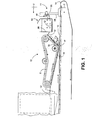
- FIG 1 shows the card attaching system in which the diverter collection tray operates.
- a card depositing feeder 15 receives cards 12 that are individually placed on sheets 13 that are transported on a transport belt 14.
- the paper sheets 13 will typically have an adhesive material placed on them at the position where the cards are to be attached.
- a feeder belt 6 in the feeder 15 moves the cards 12 through the feeder 15 mechanism.
- the cards 12 are released from the feeder 15 and they can be pressed into position on the sheet 13 by a roller 17.
- a diverter mechanism 18 will move to change the path of a rejected card 12 away from the feeder 15 opening, in an upward direction to a diverted card collection tray 10.
- Typical reasons for diverting a card may be that the card is damaged, the card is unreadable, the card is not the expected card for the particular mail piece that is being prepared, or there may be a problem with the sheet 13, such that it cannot accept the card 12.
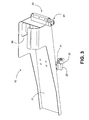
- the diverted card 12 is ejected from the divert path of the feeder 15 into the tray 10, through tray opening 30, as seen in Figures 2 and 3 .
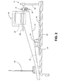
- the tray 10 includes a downward sloped chute 21, that starts above the area of belt 14, where the sheets 13 are transported, and ends at a lower point, preferably away from the moving parts of the device and outside of the apparatus.
- the chute extends through a gap in the protective cover 20 that is usually in place over the moving components.
- the cards 12 that slide down the chute 21 can then be collected by an operator without opening the cover 20, or the cards 12 can be allowed to drop into a receptacle outside the covers 20.
- a jogging or vibrating motion is imparted on to the tray 10 to assist movement of cards 12 down the chute 21.
- the tray 10 is supported from underneath by a mounting assembly 23 and a jogging roller 22.
- the jogging roller 22 rests on top of the belt 14 and rolls along as the belt 14 moves.
- the roller 22 is configured to impart a vertical motion to the tray 10, thereby providing the desired jogging motion to the cards 12 contained therein.
- the roller 22 includes one or more flattened surfaces 31.
- the axis of the roller 22 can be positioned eccentrically (not in the center), so that an uneven vertical motion is generated.
- the roller 22 can also be other non-circular shapes, such as an oval.
- the tray 10 is also supported by vibration mounted hinge 24 that connects to the structure of the card attaching system via vertical member 25 and horizontal member 26.
- a movable mounting mechanism 41 supports a hinge shaft 42 around which the tray hinge mounting 44 can pivot.
- the tray mounting 44 is vibration isolated from the rest of the structure connecting to the card attaching system. Accordingly, in between the hinge shaft 42 and the tray hinge mounting 44, a vibration absorbing material 43 such as rubber, or other elastomeric material, is also used in the mounting 44.
Landscapes
- Engineering & Computer Science (AREA)
- Mechanical Engineering (AREA)
- Feeding Of Articles By Means Other Than Belts Or Rollers (AREA)
Abstract

Description
- The present invention relates to error handling in an automated system for attachment of cards, such as plastic cards, to mail items in a mail production machine.
- A mail insertion system or a "mailpiece inserter" is commonly employed for producing mailpieces intended for mass mail communications. Such mailpiece inserters are typically used by organizations such as banks, insurance companies and utility companies for producing a large volume of specific mail communications where the contents of each mailpiece are directed to a particular addressee.
- In many respects, a typical inserter resembles a manufacturing assembly line. Sheets and other raw materials (i.e., a web of paper stock, enclosures, and envelopes) enter the inserter system as inputs. Various modules or workstations in the inserter system work cooperatively to process the sheets until a finished mail piece is produced. The precise configuration of each inserter system depends upon the needs of each customer or installation.
- Typically, inserter systems prepare mall pieces by arranging preprinted sheets of material into a collation, i.e., the content material of the mail piece, on a transport deck. The collation of preprinted sheets may continue to a chassis module where additional sheets or inserts may be added based upon predefined criteria, e.g., an insert being sent to addressees in a particular geographic region. Once filled, the envelopes are closed, sealed, weighed, and sorted. A postage meter may then be used to apply postage indicia based upon the weight and/or size of the mail piece. The mailpieces will then be moved to a stacker where mailpieces are collected and stacked, either on edge or laid flat.
- In one particular implementation of an inserter system, a card, such as a credit card, a membership card, or the like, made from a material such as plastic is included in the mail collation. In such systems, individual cards are removed from a stack of cards to be attached to sheets of paper that are them folded and included in a mail collation. Cards are typically held in place on the sheets by an adhesive that is deposited on the sheet upstream of the card feeder location.
- Before they are attached to the sheets, the cards are checked to make sure that they conform to the intended mail piece. If the card cannot be properly read, or if it is damaged, or if it appears to be out of sequence, then, rather than shutting down the inserter system, the individual card can be diverted away from normal processing and collected in a reject bin. Alternatively, a problem with some other part of the mail piece might make it necessary to divert the card.
- Since rejected cards must be periodically emptied from the reject bin, there is a need to provide a safe and efficient means for an operator to get access to the cards, so that the bin does not overflow. In a typical arrangement, the operator would need to open the covers of the inserter system in order to get access to the bin. Opening the covers on this type of equipment exposes the operator to moving parts that could cause an injury. Alternatively, the system can be paused while such an operation is carried out.
- The proposed tray solves the problems of emptying a reject bin by substituting a tray with a sloped chute that leads out of the equipment. Cards can slide down the chute to an endpoint outside of the covers of the machine, such that the covers don't need to be opened to retrieve the diverted cards. A shaking motion is added to the tray to assist in the movement of cards down the chute. In the preferred embodiment, the shaking motion is supplied without any additional power source or any additional actuating mechanism.
- More particularly, the invention provides an automated apparatus and method for collecting and dispensing rejected cards in a tray in a card attaching system. Sheets of paper are transported on a moving belt. Cards are fed from a card feeder positioned above the moving belt and cards are deposited onto the sheets of paper transported on the moving belt.
- When a card rejection condition is detected, a defective card cannot be attached to the sheet. The rejected card is diverted and deposited in a tray having a sloped chute. The tray receives diverted cards from the card feeder at an elevated position over the moving belt. The tray includes a sloped chute extending down to a lower position beyond an outside edge of the moving belt.
- To facilitate movement of the cards down the chute, the tray is vibrated. In the preferred embodiment this vibration is accomplished by supporting the tray on a roller assembly that is positioned to roll on a surface of the moving belt as it passes under the sloped chute. To impart the vibration, the roller is non-circular and/or of an eccentric configuration, such that the axis of the roller will experience a vertical displacement during rotation.
- In preferred embodiments, the roller can includes a circular wheel with at least one flattened side on its perimeter, and/or a circular wheel with an off-center axis of rotation. Alternatively, the roller can comprise an oval wheel, or other non-circular shape.
- In another preferred embodiment, the tray is connected to the card attaching system with a vibration isolation mounting to minimize vibration transfer to the card attaching system.
-
Figure 1 shows a side view of the card attaching system with the divert tray. -
Figure 2 shows positioning of the vibrating tray above the moving belt from an end view of the card attaching system. -
Figure 3 is an isometric view of the tray assembly. -
Figure 4 shows details of the tray mounting mechanism to the card attaching system. -
Figure 1 shows the card attaching system in which the diverter collection tray operates. Acard depositing feeder 15 receivescards 12 that are individually placed onsheets 13 that are transported on atransport belt 14. Thepaper sheets 13 will typically have an adhesive material placed on them at the position where the cards are to be attached. Afeeder belt 6 in thefeeder 15 moves thecards 12 through thefeeder 15 mechanism. Thecards 12 are released from thefeeder 15 and they can be pressed into position on thesheet 13 by aroller 17. - In some cases, it will be determined that a
card 12 cannot be placed on asheet 13, and adiverter mechanism 18 will move to change the path of a rejectedcard 12 away from thefeeder 15 opening, in an upward direction to a divertedcard collection tray 10. Typical reasons for diverting a card may be that the card is damaged, the card is unreadable, the card is not the expected card for the particular mail piece that is being prepared, or there may be a problem with thesheet 13, such that it cannot accept thecard 12. - The diverted
card 12 is ejected from the divert path of thefeeder 15 into thetray 10, through tray opening 30, as seen inFigures 2 and3 . Thetray 10 includes a downwardsloped chute 21, that starts above the area ofbelt 14, where thesheets 13 are transported, and ends at a lower point, preferably away from the moving parts of the device and outside of the apparatus. - As seen in
Fig. 2 , in a preferred embodiment the chute extends through a gap in theprotective cover 20 that is usually in place over the moving components. Thecards 12 that slide down thechute 21 can then be collected by an operator without opening thecover 20, or thecards 12 can be allowed to drop into a receptacle outside thecovers 20. - In the preferred embodiment, a jogging or vibrating motion is imparted on to the
tray 10 to assist movement ofcards 12 down thechute 21. To this end, thetray 10 is supported from underneath by amounting assembly 23 and ajogging roller 22. Thejogging roller 22 rests on top of thebelt 14 and rolls along as thebelt 14 moves. Theroller 22 is configured to impart a vertical motion to thetray 10, thereby providing the desired jogging motion to thecards 12 contained therein. An advantage of using thejogging roller 22 in combination with thetray 10 is that no additional power source or actuator is needed to provide this desired motion. - In one embodiment, the
roller 22 includes one or moreflattened surfaces 31. Alternatively, the axis of theroller 22 can be positioned eccentrically (not in the center), so that an uneven vertical motion is generated. Theroller 22 can also be other non-circular shapes, such as an oval. - As seen in
Figures 2 ,3 , and4 , thetray 10 is also supported by vibration mountedhinge 24 that connects to the structure of the card attaching system viavertical member 25 andhorizontal member 26. Amovable mounting mechanism 41 supports ahinge shaft 42 around which the tray hinge mounting 44 can pivot. In the preferred embodiment, thetray mounting 44 is vibration isolated from the rest of the structure connecting to the card attaching system. Accordingly, in between thehinge shaft 42 and the tray hinge mounting 44, avibration absorbing material 43 such as rubber, or other elastomeric material, is also used in the mounting 44. - Although the invention has been described with respect to preferred embodiments thereof, it will be understood by those skilled in the art that the foregoing and various other changes, omissions and deviations in the form and detail thereof may be made without departing from the scope of this invention defined in the claims.
Claims (15)
- A tray for collecting and dispensing diverted cards in a card attaching system, wherein the card attaching system includes a card feeder positioned above a moving belt for depositing cards onto sheets of paper transported on the moving belt, and wherein the card feeder includes a divert mechanism for diverting rejected cards onto an alternate card path so that the rejected cards are not deposited, and are collected in the tray, the tray comprising:a sloped chute positioned to receive diverted cards from the card feeder at an elevated position over the moving belt and extending down to a lower position beyond an outside edge of the moving belt; anda chute support extending from the chute to a surface of the moving belt; the chute support resting on a roller that is positioned to roll on a surface of the moving belt as it passes under the sloped chute;wherein the roller has a configuration selected from one or more of a non-circular or an eccentric configuration, such that the axis of the roller will experience a vertical displacement as the roller rotates, imparting a vertical jogging motion on the chute support and the sloped chute.
- The tray of claim 1 wherein the roller configuration includes a circular wheel with at least one flattened side on its perimeter.
- The tray of claim 1 or claim 2 wherein the roller configuration includes a circular wheel with an off-center axis of rotation.
- The tray of claim 1 wherein the roller configuration includes an oval wheel.
- The tray of any preceding claim, further including a support bracket for supporting the tray on the card attaching system, and wherein the support bracket uses a vibration isolation mounting to connect to the card attaching system.
- A card attaching system with a tray for collecting and dispensing diverted cards, including:a moving belt that transports sheets of paper on which cards will be deposited;a card feeder positioned above the moving belt and depositing cards onto sheets of paper transported on the moving belt, the card feeder including a divert mechanism for diverting rejected cards onto an alternate card path to a tray, so that the rejected cards are not deposited;wherein the tray comprises:a sloped chute positioned to receive diverted cards from the card feeder at an elevated position over the moving belt and extending down to a lower position beyond an outside edge of the moving belt; anda chute support extending from the chute to a surface of the moving belt; the chute support resting on a roller that is positioned to roll on a surface of the moving belt as it passes under the sloped chute;wherein the roller has a configuration selected from one or more of a non-circular or an eccentric configuration, such that the axis of the roller will experience a vertical displacement as the roller rotates, imparting a vertical jogging motion on the chute support and the sloped chute.
- The card attaching system of claim 6 wherein the roller configuration includes a circular wheel with at least one flattened side on its perimeter.
- The card attaching system of claim 6 or claim 7 wherein the roller configuration includes a circular wheel with an off-center axis of rotation.
- The card attaching system of claim 6 wherein the roller configuration includes an oval wheel.
- The card attaching system of any of claims 6 to 9 further including a support bracket for supporting the tray on the card attaching system, and wherein the support bracket uses a vibration isolation mounting to connect to the card attaching system.
- A method of collecting and dispensing rejected cards in a tray in a card attaching system, the method including:transporting sheets of paper on a moving belt;feeding cards from a card feeder positioned above the moving belt and depositing cards onto the sheets of paper transported on the moving belt;detecting a condition that requires diverting a rejected card prior to being deposited on the sheets of paper;diverting the rejected card to a tray having a sloped chute positioned to receive diverted cards from the card feeder at an elevated position over the moving belt and extending down to a lower position beyond an outside edge of the moving belt;vibrating the tray by supporting the tray on a chute support resting on a roller that is positioned to roll on a surface of the moving belt as it passes under the sloped chute and wherein the roller has a configuration selected from one or more of a non-circular or an eccentric configuration, such that the axis of the roller will experience a vertical displacement as the roller rotates, imparting a vertical jogging motion on the chute support and the sloped chute.
- The method of claim 11 wherein the roller configuration includes a circular wheel with at least one flattened side on its perimeter.
- The method of claim 11 or claim 12 wherein the roller configuration includes a circular wheel with an off-center axis of rotation.
- The method of claim 11 wherein the roller configuration includes an oval wheel.
- The method of any of claims 11 to 14 further including step of supporting the tray on the card attaching system with a vibration isolation mounting to connect to the card attaching system.
Applications Claiming Priority (1)
| Application Number | Priority Date | Filing Date | Title |
|---|---|---|---|
| US14/561,653 US9511944B2 (en) | 2014-12-05 | 2014-12-05 | Vibrating tray for diverted card inserts |
Publications (2)
| Publication Number | Publication Date |
|---|---|
| EP3028974A1 true EP3028974A1 (en) | 2016-06-08 |
| EP3028974B1 EP3028974B1 (en) | 2017-07-05 |
Family
ID=54477931
Family Applications (1)
| Application Number | Title | Priority Date | Filing Date |
|---|---|---|---|
| EP15193620.0A Not-in-force EP3028974B1 (en) | 2014-12-05 | 2015-11-09 | A tray, a card attaching system, and a method of collecting and dispensing rejected cards |
Country Status (2)
| Country | Link |
|---|---|
| US (1) | US9511944B2 (en) |
| EP (1) | EP3028974B1 (en) |
Citations (2)
| Publication number | Priority date | Publication date | Assignee | Title |
|---|---|---|---|---|
| GB866154A (en) * | 1958-04-17 | 1961-04-26 | Ibm | Card stacking device |
| US20040089706A1 (en) * | 2001-02-22 | 2004-05-13 | Hill Gregory S | Card package production system having multidirectinal card package distribution module with stacker and reject gate and method |
Family Cites Families (3)
| Publication number | Priority date | Publication date | Assignee | Title |
|---|---|---|---|---|
| US2570288A (en) * | 1949-05-03 | 1951-10-09 | Howard Paper Mills Inc | Photoelectric inspection of sheet materials |
| GB2102758B (en) * | 1981-07-10 | 1985-02-27 | Pa Management Consult | Packaging goods in pocketed trays |
| US20090152177A1 (en) * | 2006-05-12 | 2009-06-18 | Hanaar Corp. | Optical paper sorting system, method and apparatus |
-
2014
- 2014-12-05 US US14/561,653 patent/US9511944B2/en not_active Expired - Fee Related
-
2015
- 2015-11-09 EP EP15193620.0A patent/EP3028974B1/en not_active Not-in-force
Patent Citations (2)
| Publication number | Priority date | Publication date | Assignee | Title |
|---|---|---|---|---|
| GB866154A (en) * | 1958-04-17 | 1961-04-26 | Ibm | Card stacking device |
| US20040089706A1 (en) * | 2001-02-22 | 2004-05-13 | Hill Gregory S | Card package production system having multidirectinal card package distribution module with stacker and reject gate and method |
Also Published As
| Publication number | Publication date |
|---|---|
| US20160159576A1 (en) | 2016-06-09 |
| US9511944B2 (en) | 2016-12-06 |
| EP3028974B1 (en) | 2017-07-05 |
Similar Documents
| Publication | Publication Date | Title |
|---|---|---|
| EP1587640B1 (en) | Method for sorting flat postal items according to the order of distribution | |
| JP2006527076A (en) | Mail processing method | |
| US9914600B2 (en) | Method for automated filling of a mail tray from a vertical stacker | |
| KR101929927B1 (en) | Automatic apparatus for treating returned postal matters | |
| US6386537B1 (en) | Sheet accumulator with diverting mechanisms | |
| KR20070059092A (en) | Mail classification method and apparatus | |
| US9511944B2 (en) | Vibrating tray for diverted card inserts | |
| US5626001A (en) | Shingled material roll feed for mail insertion system | |
| EP1792862B1 (en) | Apparatus for handling mailpieces | |
| US6793212B2 (en) | On-edge envelope stacker adjustable for different sized articles | |
| US6840384B2 (en) | Gate assembly for diverting articles and the like | |
| US9573709B2 (en) | Inter-machine buffer for mailpiece fabrication system | |
| KR100367332B1 (en) | Mail sorter | |
| US8215629B2 (en) | System and method for producing and arranging sheet material for use in a mailpiece inserter | |
| EP1371589B1 (en) | Flat article transport and aligner system | |
| JP4281321B2 (en) | Non-standard-size mail sorting, sorting and stamping processing equipment | |
| US20130318929A1 (en) | Method and apparatus for automated filling of mail trays | |
| US20050242005A1 (en) | Gate assembly for diverting articles and the like | |
| GB2212483A (en) | Mailing machine; sensing thickness | |
| EP1728745B1 (en) | Cut sheet feeder | |
| US8327993B2 (en) | Safety device for a linear actuation system | |
| EP2172408A2 (en) | Item transport system with air divert module | |
| AU2009332839B2 (en) | Postal sorting machine including a manual feeding station | |
| CA2548710C (en) | Platen for cut sheet feeder | |
| EP3693306B1 (en) | Method for franking mail items fed to a franking machine, and device for executing the method |
Legal Events
| Date | Code | Title | Description |
|---|---|---|---|
| PUAI | Public reference made under article 153(3) epc to a published international application that has entered the european phase |
Free format text: ORIGINAL CODE: 0009012 |
|
| AK | Designated contracting states |
Kind code of ref document: A1 Designated state(s): AL AT BE BG CH CY CZ DE DK EE ES FI FR GB GR HR HU IE IS IT LI LT LU LV MC MK MT NL NO PL PT RO RS SE SI SK SM TR |
|
| AX | Request for extension of the european patent |
Extension state: BA ME |
|
| 17P | Request for examination filed |
Effective date: 20161012 |
|
| RBV | Designated contracting states (corrected) |
Designated state(s): AL AT BE BG CH CY CZ DE DK EE ES FI FR GB GR HR HU IE IS IT LI LT LU LV MC MK MT NL NO PL PT RO RS SE SI SK SM TR |
|
| GRAP | Despatch of communication of intention to grant a patent |
Free format text: ORIGINAL CODE: EPIDOSNIGR1 |
|
| INTG | Intention to grant announced |
Effective date: 20170327 |
|
| GRAS | Grant fee paid |
Free format text: ORIGINAL CODE: EPIDOSNIGR3 |
|
| GRAA | (expected) grant |
Free format text: ORIGINAL CODE: 0009210 |
|
| AK | Designated contracting states |
Kind code of ref document: B1 Designated state(s): AL AT BE BG CH CY CZ DE DK EE ES FI FR GB GR HR HU IE IS IT LI LT LU LV MC MK MT NL NO PL PT RO RS SE SI SK SM TR |
|
| REG | Reference to a national code |
Ref country code: GB Ref legal event code: FG4D |
|
| REG | Reference to a national code |
Ref country code: CH Ref legal event code: EP |
|
| REG | Reference to a national code |
Ref country code: AT Ref legal event code: REF Ref document number: 906447 Country of ref document: AT Kind code of ref document: T Effective date: 20170715 |
|
| REG | Reference to a national code |
Ref country code: IE Ref legal event code: FG4D |
|
| REG | Reference to a national code |
Ref country code: DE Ref legal event code: R096 Ref document number: 602015003432 Country of ref document: DE |
|
| REG | Reference to a national code |
Ref country code: NL Ref legal event code: MP Effective date: 20170705 |
|
| REG | Reference to a national code |
Ref country code: AT Ref legal event code: MK05 Ref document number: 906447 Country of ref document: AT Kind code of ref document: T Effective date: 20170705 |
|
| REG | Reference to a national code |
Ref country code: LT Ref legal event code: MG4D Ref country code: FR Ref legal event code: PLFP Year of fee payment: 3 |
|
| PG25 | Lapsed in a contracting state [announced via postgrant information from national office to epo] |
Ref country code: SE Free format text: LAPSE BECAUSE OF FAILURE TO SUBMIT A TRANSLATION OF THE DESCRIPTION OR TO PAY THE FEE WITHIN THE PRESCRIBED TIME-LIMIT Effective date: 20170705 Ref country code: FI Free format text: LAPSE BECAUSE OF FAILURE TO SUBMIT A TRANSLATION OF THE DESCRIPTION OR TO PAY THE FEE WITHIN THE PRESCRIBED TIME-LIMIT Effective date: 20170705 Ref country code: NO Free format text: LAPSE BECAUSE OF FAILURE TO SUBMIT A TRANSLATION OF THE DESCRIPTION OR TO PAY THE FEE WITHIN THE PRESCRIBED TIME-LIMIT Effective date: 20171005 Ref country code: AT Free format text: LAPSE BECAUSE OF FAILURE TO SUBMIT A TRANSLATION OF THE DESCRIPTION OR TO PAY THE FEE WITHIN THE PRESCRIBED TIME-LIMIT Effective date: 20170705 Ref country code: LT Free format text: LAPSE BECAUSE OF FAILURE TO SUBMIT A TRANSLATION OF THE DESCRIPTION OR TO PAY THE FEE WITHIN THE PRESCRIBED TIME-LIMIT Effective date: 20170705 Ref country code: NL Free format text: LAPSE BECAUSE OF FAILURE TO SUBMIT A TRANSLATION OF THE DESCRIPTION OR TO PAY THE FEE WITHIN THE PRESCRIBED TIME-LIMIT Effective date: 20170705 Ref country code: HR Free format text: LAPSE BECAUSE OF FAILURE TO SUBMIT A TRANSLATION OF THE DESCRIPTION OR TO PAY THE FEE WITHIN THE PRESCRIBED TIME-LIMIT Effective date: 20170705 |
|
| PG25 | Lapsed in a contracting state [announced via postgrant information from national office to epo] |
Ref country code: LV Free format text: LAPSE BECAUSE OF FAILURE TO SUBMIT A TRANSLATION OF THE DESCRIPTION OR TO PAY THE FEE WITHIN THE PRESCRIBED TIME-LIMIT Effective date: 20170705 Ref country code: BG Free format text: LAPSE BECAUSE OF FAILURE TO SUBMIT A TRANSLATION OF THE DESCRIPTION OR TO PAY THE FEE WITHIN THE PRESCRIBED TIME-LIMIT Effective date: 20171005 Ref country code: IS Free format text: LAPSE BECAUSE OF FAILURE TO SUBMIT A TRANSLATION OF THE DESCRIPTION OR TO PAY THE FEE WITHIN THE PRESCRIBED TIME-LIMIT Effective date: 20171105 Ref country code: ES Free format text: LAPSE BECAUSE OF FAILURE TO SUBMIT A TRANSLATION OF THE DESCRIPTION OR TO PAY THE FEE WITHIN THE PRESCRIBED TIME-LIMIT Effective date: 20170705 Ref country code: GR Free format text: LAPSE BECAUSE OF FAILURE TO SUBMIT A TRANSLATION OF THE DESCRIPTION OR TO PAY THE FEE WITHIN THE PRESCRIBED TIME-LIMIT Effective date: 20171006 Ref country code: PL Free format text: LAPSE BECAUSE OF FAILURE TO SUBMIT A TRANSLATION OF THE DESCRIPTION OR TO PAY THE FEE WITHIN THE PRESCRIBED TIME-LIMIT Effective date: 20170705 Ref country code: RS Free format text: LAPSE BECAUSE OF FAILURE TO SUBMIT A TRANSLATION OF THE DESCRIPTION OR TO PAY THE FEE WITHIN THE PRESCRIBED TIME-LIMIT Effective date: 20170705 |
|
| REG | Reference to a national code |
Ref country code: DE Ref legal event code: R097 Ref document number: 602015003432 Country of ref document: DE |
|
| PG25 | Lapsed in a contracting state [announced via postgrant information from national office to epo] |
Ref country code: CZ Free format text: LAPSE BECAUSE OF FAILURE TO SUBMIT A TRANSLATION OF THE DESCRIPTION OR TO PAY THE FEE WITHIN THE PRESCRIBED TIME-LIMIT Effective date: 20170705 Ref country code: RO Free format text: LAPSE BECAUSE OF FAILURE TO SUBMIT A TRANSLATION OF THE DESCRIPTION OR TO PAY THE FEE WITHIN THE PRESCRIBED TIME-LIMIT Effective date: 20170705 Ref country code: DK Free format text: LAPSE BECAUSE OF FAILURE TO SUBMIT A TRANSLATION OF THE DESCRIPTION OR TO PAY THE FEE WITHIN THE PRESCRIBED TIME-LIMIT Effective date: 20170705 |
|
| PLBE | No opposition filed within time limit |
Free format text: ORIGINAL CODE: 0009261 |
|
| STAA | Information on the status of an ep patent application or granted ep patent |
Free format text: STATUS: NO OPPOSITION FILED WITHIN TIME LIMIT |
|
| PG25 | Lapsed in a contracting state [announced via postgrant information from national office to epo] |
Ref country code: EE Free format text: LAPSE BECAUSE OF FAILURE TO SUBMIT A TRANSLATION OF THE DESCRIPTION OR TO PAY THE FEE WITHIN THE PRESCRIBED TIME-LIMIT Effective date: 20170705 Ref country code: SM Free format text: LAPSE BECAUSE OF FAILURE TO SUBMIT A TRANSLATION OF THE DESCRIPTION OR TO PAY THE FEE WITHIN THE PRESCRIBED TIME-LIMIT Effective date: 20170705 Ref country code: SK Free format text: LAPSE BECAUSE OF FAILURE TO SUBMIT A TRANSLATION OF THE DESCRIPTION OR TO PAY THE FEE WITHIN THE PRESCRIBED TIME-LIMIT Effective date: 20170705 Ref country code: IT Free format text: LAPSE BECAUSE OF FAILURE TO SUBMIT A TRANSLATION OF THE DESCRIPTION OR TO PAY THE FEE WITHIN THE PRESCRIBED TIME-LIMIT Effective date: 20170705 |
|
| 26N | No opposition filed |
Effective date: 20180406 |
|
| PG25 | Lapsed in a contracting state [announced via postgrant information from national office to epo] |
Ref country code: MC Free format text: LAPSE BECAUSE OF FAILURE TO SUBMIT A TRANSLATION OF THE DESCRIPTION OR TO PAY THE FEE WITHIN THE PRESCRIBED TIME-LIMIT Effective date: 20170705 |
|
| PG25 | Lapsed in a contracting state [announced via postgrant information from national office to epo] |
Ref country code: LU Free format text: LAPSE BECAUSE OF NON-PAYMENT OF DUE FEES Effective date: 20171109 Ref country code: SI Free format text: LAPSE BECAUSE OF FAILURE TO SUBMIT A TRANSLATION OF THE DESCRIPTION OR TO PAY THE FEE WITHIN THE PRESCRIBED TIME-LIMIT Effective date: 20170705 |
|
| REG | Reference to a national code |
Ref country code: BE Ref legal event code: MM Effective date: 20171130 |
|
| REG | Reference to a national code |
Ref country code: IE Ref legal event code: MM4A |
|
| PG25 | Lapsed in a contracting state [announced via postgrant information from national office to epo] |
Ref country code: MT Free format text: LAPSE BECAUSE OF NON-PAYMENT OF DUE FEES Effective date: 20171109 |
|
| PG25 | Lapsed in a contracting state [announced via postgrant information from national office to epo] |
Ref country code: IE Free format text: LAPSE BECAUSE OF NON-PAYMENT OF DUE FEES Effective date: 20171109 |
|
| PG25 | Lapsed in a contracting state [announced via postgrant information from national office to epo] |
Ref country code: BE Free format text: LAPSE BECAUSE OF NON-PAYMENT OF DUE FEES Effective date: 20171130 |
|
| PGFP | Annual fee paid to national office [announced via postgrant information from national office to epo] |
Ref country code: DE Payment date: 20181128 Year of fee payment: 4 |
|
| PGFP | Annual fee paid to national office [announced via postgrant information from national office to epo] |
Ref country code: FR Payment date: 20181127 Year of fee payment: 4 |
|
| PG25 | Lapsed in a contracting state [announced via postgrant information from national office to epo] |
Ref country code: HU Free format text: LAPSE BECAUSE OF FAILURE TO SUBMIT A TRANSLATION OF THE DESCRIPTION OR TO PAY THE FEE WITHIN THE PRESCRIBED TIME-LIMIT; INVALID AB INITIO Effective date: 20151109 |
|
| REG | Reference to a national code |
Ref country code: CH Ref legal event code: PL |
|
| PG25 | Lapsed in a contracting state [announced via postgrant information from national office to epo] |
Ref country code: CH Free format text: LAPSE BECAUSE OF NON-PAYMENT OF DUE FEES Effective date: 20181130 Ref country code: LI Free format text: LAPSE BECAUSE OF NON-PAYMENT OF DUE FEES Effective date: 20181130 |
|
| PG25 | Lapsed in a contracting state [announced via postgrant information from national office to epo] |
Ref country code: CY Free format text: LAPSE BECAUSE OF FAILURE TO SUBMIT A TRANSLATION OF THE DESCRIPTION OR TO PAY THE FEE WITHIN THE PRESCRIBED TIME-LIMIT Effective date: 20170705 |
|
| PG25 | Lapsed in a contracting state [announced via postgrant information from national office to epo] |
Ref country code: MK Free format text: LAPSE BECAUSE OF FAILURE TO SUBMIT A TRANSLATION OF THE DESCRIPTION OR TO PAY THE FEE WITHIN THE PRESCRIBED TIME-LIMIT Effective date: 20170705 |
|
| PG25 | Lapsed in a contracting state [announced via postgrant information from national office to epo] |
Ref country code: TR Free format text: LAPSE BECAUSE OF FAILURE TO SUBMIT A TRANSLATION OF THE DESCRIPTION OR TO PAY THE FEE WITHIN THE PRESCRIBED TIME-LIMIT Effective date: 20170705 |
|
| PG25 | Lapsed in a contracting state [announced via postgrant information from national office to epo] |
Ref country code: PT Free format text: LAPSE BECAUSE OF FAILURE TO SUBMIT A TRANSLATION OF THE DESCRIPTION OR TO PAY THE FEE WITHIN THE PRESCRIBED TIME-LIMIT Effective date: 20170705 |
|
| REG | Reference to a national code |
Ref country code: DE Ref legal event code: R119 Ref document number: 602015003432 Country of ref document: DE |
|
| PG25 | Lapsed in a contracting state [announced via postgrant information from national office to epo] |
Ref country code: AL Free format text: LAPSE BECAUSE OF FAILURE TO SUBMIT A TRANSLATION OF THE DESCRIPTION OR TO PAY THE FEE WITHIN THE PRESCRIBED TIME-LIMIT Effective date: 20170705 |
|
| GBPC | Gb: european patent ceased through non-payment of renewal fee |
Effective date: 20191109 |
|
| PG25 | Lapsed in a contracting state [announced via postgrant information from national office to epo] |
Ref country code: GB Free format text: LAPSE BECAUSE OF NON-PAYMENT OF DUE FEES Effective date: 20191109 Ref country code: DE Free format text: LAPSE BECAUSE OF NON-PAYMENT OF DUE FEES Effective date: 20200603 Ref country code: FR Free format text: LAPSE BECAUSE OF NON-PAYMENT OF DUE FEES Effective date: 20191130 |