EP3028967A1 - Paper feeding apparatus and image forming apparatus - Google Patents
Paper feeding apparatus and image forming apparatus Download PDFInfo
- Publication number
- EP3028967A1 EP3028967A1 EP14833067.3A EP14833067A EP3028967A1 EP 3028967 A1 EP3028967 A1 EP 3028967A1 EP 14833067 A EP14833067 A EP 14833067A EP 3028967 A1 EP3028967 A1 EP 3028967A1
- Authority
- EP
- European Patent Office
- Prior art keywords
- friction pad
- pickup roller
- state
- paper
- curvature
- Prior art date
- Legal status (The legal status is an assumption and is not a legal conclusion. Google has not performed a legal analysis and makes no representation as to the accuracy of the status listed.)
- Withdrawn
Links
Images


Classifications
-
- B—PERFORMING OPERATIONS; TRANSPORTING
- B65—CONVEYING; PACKING; STORING; HANDLING THIN OR FILAMENTARY MATERIAL
- B65H—HANDLING THIN OR FILAMENTARY MATERIAL, e.g. SHEETS, WEBS, CABLES
- B65H3/00—Separating articles from piles
- B65H3/46—Supplementary devices or measures to assist separation or prevent double feed
- B65H3/52—Friction retainers acting on under or rear side of article being separated
- B65H3/5207—Non-driven retainers, e.g. movable retainers being moved by the motion of the article
- B65H3/5215—Non-driven retainers, e.g. movable retainers being moved by the motion of the article the retainers positioned under articles separated from the top of the pile
- B65H3/5223—Retainers of the pad-type, e.g. friction pads
-
- B—PERFORMING OPERATIONS; TRANSPORTING
- B65—CONVEYING; PACKING; STORING; HANDLING THIN OR FILAMENTARY MATERIAL
- B65H—HANDLING THIN OR FILAMENTARY MATERIAL, e.g. SHEETS, WEBS, CABLES
- B65H3/00—Separating articles from piles
- B65H3/02—Separating articles from piles using friction forces between articles and separator
- B65H3/06—Rollers or like rotary separators
- B65H3/0638—Construction of the rollers or like rotary separators
-
- B—PERFORMING OPERATIONS; TRANSPORTING
- B65—CONVEYING; PACKING; STORING; HANDLING THIN OR FILAMENTARY MATERIAL
- B65H—HANDLING THIN OR FILAMENTARY MATERIAL, e.g. SHEETS, WEBS, CABLES
- B65H2404/00—Parts for transporting or guiding the handled material
- B65H2404/10—Rollers
- B65H2404/11—Details of cross-section or profile
- B65H2404/114—Built-up elements
- B65H2404/1141—Built-up elements covering a part of the periphery
Definitions
- the present invention relates to a paper feeding apparatus and an image forming apparatus, and more particularly, it relates to a paper feeding apparatus and an image forming apparatus each including a pickup roller.
- a paper feeding apparatus including a pickup roller is known in general (refer to Patent Document 1, for example).
- a paper feeding apparatus including a rotatable pickup roller including a paper feed portion that picks up stacked paper while contacting with a surface of the stacked paper in a first state where the paper is to be picked up and a hub that contacts with the surface of the paper picked up in the first state in a second state where the paper is to be transported.
- This paper feeding apparatus includes a separation pad (friction pad) that is arranged to face the pickup roller and suppresses transport of subsequent paper by contacting with the paper subsequent to the paper picked up in the first state.
- the pickup roller is configured such that the paper feed portion is urged (pushed) to the separation pad in the first state and the hub is urged (pushed) to the separation pad in the second state.
- a portion of the hub that faces the separation pad has an area smaller than the area of a portion of the paper feed portion that faces the separation pad.
- Patent Document 1 Japanese Patent No. 4385929
- the portion of the hub of the pickup roller that faces the separation pad has the area smaller than the area of the portion of the paper feed portion that faces the separation pad, and hence in the second state, the hub is urged (pushed) to the separation pad in a state where a contact area between the separation pad and the hub is small.
- the contact area between the separation pad and the hub is small in the second state, and hence pressure applied to the separation pad is large. Consequently, the separation pad easily becomes worn or damaged.
- the present invention has been proposed in order to solve the aforementioned problem, and one object of the present invention is to provide a paper feeding apparatus and an image forming apparatus each capable of suppressing tendency to wear and damage a friction pad.
- a paper feeding apparatus includes a rotatable pickup roller including a first portion that picks up stacked paper while contacting with a surface of the paper in a first state where the paper is to be picked up and a second portion that transports the paper picked up in the first state while contacting with the surface of the paper in a second state where the paper is to be transported and a friction pad that is arranged to face the pickup roller and suppresses transport of paper subsequent to the paper picked up in the first state by contacting with the paper that is subsequent, and the pickup roller is in surface contact such that a contact area between the first portion and the friction pad in the first state and a contact area between the second portion and the friction pad in the second state are substantially equal to each other.
- the pickup roller is configured to be in surface contact such that the contact area between the first portion of the pickup roller and the friction pad in the first state and the contact area between the second portion of the pickup roller and the friction pad in the second state are substantially equal to each other.
- the second portion is urged to the friction pad in a state where the contact area between the friction pad and the second portion in the second state is substantially equal to the contact area between the friction pad and the first portion in the first state, unlike the case where the second portion is urged (pushed) to the friction pad in a state where the contact area between the friction pad and the second portion is smaller in the second state.
- an increase in pressure applied to the friction pad can be suppressed in the second state, and hence tendency to wear and damage the friction pad can be suppressed.
- the first portion of the pickup roller has a first curvature on a cross-sectional surface orthogonal to the rotation axis of the pickup roller
- the second portion of the pickup roller has a second curvature on the cross-sectional surface orthogonal to the rotation axis of the pickup roller
- the first curvature and the second curvature are set so as to bring the pickup roller into surface contact such that the contact area between the first portion and the friction pad in the first state and the contact area between the second portion and the friction pad in the second state are substantially equal to each other.
- the first curvature of the first portion and the second curvature of the second portion are adjusted, whereby surface contact between the friction pad and the first portion and surface contact between the friction pad and the second portion can be easily kept substantially the same as each other in the first state and the second state.
- the aforementioned paper feeding apparatus further includes a single urging member including a first urging portion and a second urging portion having urging force weaker than the urging force of the first urging portion, and the urging member urges the friction pad toward the pickup roller by the first urging portion in the first state and urges the friction pad toward the pickup roller by the second urging portion in the second state.
- the friction pad can be urged by the second urging portion having the urging force weaker than the urging force of the first urging portion in the second state, and hence the pressure applied to the friction pad can be further reduced in the second state than in the first state.
- tendency to wear the friction pad can be easily suppressed.
- the single (one) urging member can serve as both the first urging portion and the second urging portion having the urging force weaker than the urging force of the first urging portion, and hence the structure of the paper feeding apparatus can be simplified while an increase in the number of components can be suppressed, unlike the case where the first urging portion and the second urging portion are provided separately from each other.
- the center of curvature of the first portion and the center of curvature of the second portion are arranged in different positions, as viewed along the axis.
- the first curvature of the first portion and the second curvature of the second portion can be adjusted individually. Consequently, the surface contact between the friction pad and the first portion and the surface contact between the friction pad and the second portion can be more easily kept substantially the same as each other in the first state and the second state.
- the amount of protrusion of the pickup roller toward the friction pad is larger in the first state than in the second state.
- the position of the first portion in the first state can be further moved in a direction toward the friction pad than the position in the second state, and the position of the first portion in the second state can be further moved in a direction away from the friction pad than the position in the first state. Consequently, the paper can be easily picked up in the first state, and the paper can be transported while an increase in the pressure applied to the friction pad is suppressed in the second state.
- the center of curvature of the second portion is arranged closer to the second portion than the center of the pickup roller, and the center of curvature of the first portion is arranged closer to the first portion than the center of the pickup roller, as viewed along the axis, and in the pickup roller, the center of curvature of the second portion coincides with the rotation axis of the pickup roller.
- the position of the first portion in the first state can be further moved in the direction toward the friction pad than the position in the second state, and the position of the first portion in the second state can be further moved in the direction away from the friction pad than the position in the first state.
- the pickup roller Preferably in the aforementioned structure in which the first portion has the first curvature, in the pickup roller, a surface of the first portion having the first curvature and a surface of the second portion having the second curvature are flush with each other. According to this structure, the pickup roller can be smoothly rotated when the paper is picked up and then transported.
- the paper feeding apparatus further includes a first friction pad holding member and a second friction pad holding member that hold the friction pad, the first friction pad holding member is arranged to partition a boundary region between the first urging portion and the second urging portion of the urging member, and the second friction pad holding member is arranged to hold the second urging portion between the first friction pad holding member and the second friction pad holding member.
- the second friction pad holding member (friction pad) can be urged by the second urging portion in a state where application of the urging force of the first urging portion is suppressed in the second state even when the common urging member including the first urging portion and the second urging portion is provided.
- the first friction pad holding member includes a plate-like partition portion, and the partition portion is held between the first urging portion and the second urging portion.
- the second friction pad holding member (friction pad) can be urged by the second urging portion while the application of the urging force of the first urging portion is stably suppressed by the partition portion in the second state even when the common urging member including the first urging portion and the second urging portion is provided.
- the partition portion includes an engaging portion that engages with the urging member. According to this structure, misalignment of the partition portion and the urging member can be suppressed.
- the movement of the first friction pad holding member toward the pickup roller is restricted in the second state, and the second friction pad holding member is urged toward the pickup roller by urging of the second urging portion in a state where the movement of the first friction pad holding member is restricted in the second state.
- the movement of the first friction pad holding member toward the pickup roller is restricted in the second state so that the application of the urging force of the first urging portion can be suppressed, and hence the second friction pad holding member (friction pad) can be more easily urged by the second urging portion.
- the first urging portion of the urging member is a first spring portion
- the second urging portion of the urging member is a coil spring member that is a second spring portion
- the first spring portion has a first pitch
- the second spring portion has a second pitch larger than the first pitch.
- the second friction pad holding member is urged toward the pickup roller by urging of the second spring portion in a state where the first spring portion has a natural length such that the movement of the first friction pad holding member toward the pickup roller is restricted in the second state.
- generation of the urging force of the first spring portion to the first friction pad holding member can be prevented in the second state. Consequently, the movement of the first friction pad holding member toward the pickup roller is restricted so that the application of the urging force of the first urging portion can be easily suppressed.
- the second friction pad holding member is movable relative to the first friction pad holding member.
- the second friction pad holding member can be easily moved independently of the first friction pad holding member in the second state.
- the movement of the first friction pad holding member toward the pickup roller is restricted in the second state so that the application of the urging force of the first urging portion can be further suppressed.
- the first portion of the pickup roller has a first curvature
- the second portion of the pickup roller has a second curvature
- both the first friction pad holding member and the second friction pad holding member linearly move in a direction in which the urging member expands and contracts
- the first curvature of the first portion and the second curvature of the second portion are substantially equal to each other.
- the friction pad can be easily urged by the linear movement of the first friction pad holding member and the second friction pad holding member in the direction in which the urging member expands and contracts.
- the first portion of the pickup roller has a first curvature
- the second portion of the pickup roller has a second curvature
- the second friction pad holding member rotates with respect to the first friction pad holding member
- the first curvature of the first portion and the second curvature of the second portion are different from each other.
- the friction pad can be urged while a space for moving the second friction pad holding member with respect to the first friction pad holding member is further reduced, as compared with the case where the second friction pad holding member is linearly moved with respect to the first friction pad holding member in the direction in which the urging member expands and contracts, and hence a space where the second friction pad holding member is arranged can be reduced (can be compact).
- the pickup roller has a shape formed by connecting a curve having the first curvature and a curve having the second curvature, as viewed along the axis.
- the contact area between the friction pad and the first portion in the first state and the contact area between the friction pad and the second portion in the second state can be easily made substantially equal to each other.
- the first portion of the pickup roller is detachable. According to this structure, only the first portion not the entire pickup roller can be replaced when it is necessary to replace the first portion.
- An image forming apparatus includes a printing portion that prints on paper, a rotatable pickup roller including a first portion that picks up the paper that is stacked while contacting with a surface of the paper in a first state where the paper is to be picked up and a second portion that transports the paper picked up in the first state while contacting with the surface of the paper in a second state where the paper is to be transported, and a friction pad that is arranged to face the pickup roller and suppresses transport of paper subsequent to the paper picked up in the first state by contacting with the paper that is subsequent, and the pickup roller is in surface contact such that a contact area between the first portion and the friction pad in the first state and a contact area between the second portion and the friction pad in the second state are substantially equal to each other.
- the pickup roller is configured to be in surface contact such that the contact area between the first portion of the pickup roller and the friction pad in the first state and the contact area between the second portion of the pickup roller and the friction pad in the second state are substantially equal to each other.
- the second portion is urged to the friction pad in a state where the contact area between the friction pad and the second portion is substantially equal to the contact area between the friction pad and the first portion in the first state, unlike the case where the second portion is urged (pushed) to the friction pad in a state where the contact area between the friction pad and the second portion is smaller in the second state.
- an increase in pressure applied to the friction pad can be suppressed in the second state, and hence tendency to wear and damage the friction pad can be suppressed.
- the first portion of the pickup roller has a first curvature on a cross-sectional surface orthogonal to the rotation axis of the pickup roller
- the second portion of the pickup roller has a second curvature on the cross-sectional surface orthogonal to the rotation axis of the pickup roller
- the first curvature and the second curvature are set so as to bring the pickup roller into surface contact such that the contact area between the first portion and the friction pad in the first state and the contact area between the second portion and the friction pad in the second state are substantially equal to each other.
- the first curvature of the first portion and the second curvature of the second portion are adjusted, whereby surface contact between the friction pad and the first portion and surface contact between the friction pad and the second portion can be easily kept substantially the same as each other in the first state and the second state.
- the structure of a laser printer 100 according to a first embodiment of the present invention is described with reference to Figs. 1 to 9 .
- the laser printer 100 is an example of the "paper feeding apparatus” or the “image forming apparatus” in the present invention.
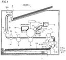
- the laser printer 100 includes a paper feed tray 1 into which paper 150 is loaded, a paper separation portion 2 configured to separate the stacked paper 150 from the paper feed tray 1 and transport the same, transport roller members 3 and 4 configured to transport the paper 150 to a printing position, and paper discharge roller members 5a to 5c configured to discharge the printed paper 150 to a paper discharge tray 6, as shown in Fig. 1 .
- the transport roller members 3 and 4 are respectively provided in pairs.
- the paper discharge roller members 5a to 5c are respectively provided in pairs.
- the laser printer 100 includes a developing device 7 that prints on transported paper 151 and a laser emitting portion 8 configured to apply laser light to a photoreceptor drum 70 of the developing device 7.
- the laser printer 100 includes a heating roller member 9 and a pressurizing roller member 10 configured to fix toner adhering to the transported paper 151.
- the paper feed tray 1 is provided with a push-up plate 11 configured to place the paper 150 to a prescribed height with respect to the paper separation portion 2.
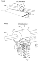
- the paper separation portion 2 is configured to separate and pick up the stacked paper 150 from the paper feed tray 1 in a first state (see Fig. 6 ) described later, as shown in Fig. 2 . Furthermore, the paper separation portion 2 is configured to transport, in a second state (see Fig. 8 ) described later, the paper 151 picked up from the paper feed tray 1 in the first state.
- the paper separation portion 2 includes a pickup roller 21, a friction pad 22, a first friction pad holding member 23, a second friction pad holding member 24, and a spring member 25, as shown in Figs. 3 and 4 .
- the paper separation portion 2 is set on a set portion 26 (see Fig. 1 ).
- the pickup roller 21 is configured to pick up (extract) the stacked paper 150 from the paper feed tray 1 and transport the same toward the developing device 7 (transport roller 4).
- the pickup roller 21 includes a first portion 21a that picks up the paper 150 while contacting with a surface of the stacked paper 150 in the first state (see Fig. 6 ) where the paper 150 is to be picked up and a second portion 21b that transports the paper picked up in the first state while contacting with a surface of the paper 151 in the second state (see Fig. 8 ) where the picked up paper 151 is to be transported, as shown in Fig. 3 .
- the pickup roller 21 includes a shaft portion 21c and is set in a housing 100a (see Fig. 1 ) to be rotatable.
- the shaft portion 21c is arranged in the second portion 21b in a state where the shaft portion 21c is eccentric from the center C of the pickup roller 21 when the pickup roller 21 is taken as a whole, as shown in Fig. 5 .
- the first portion 21a and the second portion 21b are made of rubber (EPDM (ethylene-propylene rubber), for example) having a non-slip function.
- the second portion 21b forms a main body portion of the pickup roller 21.
- the first portion 21a is configured to be detachably (replaceably) fixed to the second portion 21b.
- the pickup roller 21 is configured to operate and pick up the paper 150 from the paper feed tray 1 when the developing device 7 performs printing.
- the first portion 21a of the pickup roller 21 has a first curvature 1/R on a cross-sectional surface orthogonal to the rotation axis (shaft portion 21c) of the pickup roller 21, as shown in Fig. 5 .
- the second portion 21b of the pickup roller 21 has a second curvature 1/R on a cross-sectional surface orthogonal to the rotation axis of the pickup roller 21. More specifically, the pickup roller 21 is configured such that the first curvature 1/R of the first portion 21a and the second curvature 1/R of the second portion 21b are substantially equal to each other.
- the pickup roller 21 is formed asymmetrically, as viewed along the rotation axis (shaft portion 21c).
- the pickup roller 21 has a substantially circular shape (a near-circular shape) as a whole, as viewed along the axis.
- the first portion 21a and the second portion 21b are configured such that the center C1 of curvature of the first portion 21a and the center C2 of curvature of the second portion 21b are located in different positions.
- the rotation center of the shaft portion 21c is arranged to coincide with the center C2 of the second portion 21b.
- the pickup roller 21 is configured such that a surface of the first portion 21a having the first curvature 1/R and a surface of the second portion 21b having the second curvature 1/R are flush with each other.
- the pickup roller 21 is configured such that the center C2 of curvature of the second portion 21b is arranged closer to the second portion 21b than the center C (geometric center C) of the pickup roller 21 and the center C1 of curvature of the first portion 21a is arranged closer to the first portion 21a than the center C of the pickup roller 21, as viewed along the axis. Furthermore, the pickup roller 21 is configured such that the center C2 of curvature of the second portion 21b is eccentric from the center C of the pickup roller 21 and coincides with the rotation axis of the pickup roller 21. Moreover, the pickup roller 21 is configured such that the amount of protrusion toward the friction pad 22 is larger in the first state than in the second state.
- a distance from the rotation axis (the center C2 of curvature) of the pickup roller 21 to the friction pad 22 is D2 in the second state, as shown in Fig. 8 .
- a distance from the rotation axis of the pickup roller 21 to the friction pad 22 is D1 larger than D2 in the first state.
- the friction pad 22 is arranged to face the pickup roller 21 and is configured to suppress transport of paper 152 subsequent to the paper 151 picked up in the first state by contacting with the subsequent paper 152, as shown in Fig. 8 .
- the friction pad 22 is made of rubber (EPDM (ethylene-propylene rubber), for example) having a non-slip function.
- the pickup roller 21 is configured such that a contact area between the first portion 21a and the friction pad 22 in the first state and a contact area between the second portion 21b and the friction pad 22 in the second state are substantially equal to each other, as shown in Figs. 6 to 9 .
- the first curvature 1/R and the second curvature 1/R see Fig.
- the friction pad 22 is in a substantially arcuate shape corresponding to the shape of each of the first portion 21a and the second portion 21b of the pickup roller 21, as viewed along the rotation axis (shaft portion 21c).
- the friction pad 22 and the first portion 21a or the second portion 21b of the pickup roller 21 are configured to be in surface contact with each other.
- the friction pad 22 has substantially the same width W as the first portion 21a of the pickup roller 21 in a direction (direction X) in which the shaft portion 21c extends, as shown in Fig. 4 .
- the pickup roller 21 is configured such that the contact area between the first portion 21a and the friction pad 22 in the first state and the contact area between the second portion 21b and the friction pad 22 in the second state are substantially equal to each other in a state where the friction pad 22 and the first portion 21a or the second portion 21b of the pickup roller 21 are arranged through the transported paper 151.
- the pickup roller 21 is configured such that the contact area between the first portion 21a and the friction pad 22 in the first state and the contact area between the second portion 21b and the friction pad 22 in the second state are substantially equal to each other in a state where the transported paper 151 is held between the friction pad 22 and the first portion 21a or the second portion 21b of the pickup roller 21.
- the first friction pad holding member 23 and the second friction pad holding member 24 are configured to hold the friction pad 22, as shown in Fig. 3 .
- the first friction pad holding member 23 is configured to hold the second friction pad holding member 24 to which the friction pad 22 is fixed.
- the friction pad 22 is configured to be detachably fixed to the second friction pad holding member 24.
- Both the first friction pad holding member 23 and the second friction pad holding member 24 are configured to linearly move (move parallel) in a direction (direction P) in which the spring member 25 expands and contracts, as shown in Fig. 3 .
- the second friction pad holding member 24 is configured to be movable relative to the first friction pad holding member 23.
- the first friction pad holding member 23 is arranged to partition a boundary region 25c between a first spring portion 25a and a second spring portion 25b of the spring member 25, as shown in Figs. 3 and 4 .
- a partition portion 23a provided in the first friction pad holding member 23 that extends in a direction (direction X) substantially orthogonal to the direction (direction P) in which the spring member 25 expands and contracts is arranged in the boundary region 25c between the first spring portion 25a and the second spring portion 25b of the spring member 25.
- the partition portion 23a is plate-like.
- the partition portion 23a has a thickness smaller than a pitch in the vicinity of the boundary region 25c of the spring member 25.
- the partition portion 23a is configured to be held between the first spring portion 25a and the second spring portion 25b.
- the first friction pad holding member 23 (partition portion 23a) includes a fixing portion 23b that suppresses disengagement of the first spring portion 25a (spring member 25).
- the fixing portion 23b is configured to protrude in a direction (direction P2) in which the first spring portion 25a expands or contracts.
- the fixing portion 23b is configured to suppress disengagement of the first spring portion 25a (spring member 25) from the first friction pad holding member 23 by being fitted into an inner diameter portion of the first spring portion 25a (spring member 25). More specifically, the fixing portion 23b serves as an engaging portion that engages with the first spring portion 25a (spring member 25).
- the second friction pad holding member 24 is arranged to hold the second spring portion 25b between the second friction pad holding member 24 and the first friction pad holding member 23, as shown in Figs. 3 and 4 .
- the second friction pad holding member 24 includes a fixing portion 24a that suppresses disengagement of the second spring portion 25b (spring member 25).
- the fixing portion 24a is configured to protrude in the direction (direction P2) in which the first spring portion 25a expands or contracts.
- the fixing portion 24a is configured to suppress disengagement of the second spring portion 25b (spring member 25) from the second friction pad holding member 24 by being fitted into an inner diameter portion of the second spring portion 25b (spring member 25).
- the first friction pad holding member 23 is configured such that movement of the first friction pad holding member 23 toward the pickup roller 21 (in a direction P1) is restricted in the second state, as shown in Figs. 8 and 9 .
- the first friction pad holding member 23 is configured to be movable in the direction in which the spring member 25 expands and contracts in the first state (a state where the paper 151 is arranged between the first portion 21a and the friction pad 22).
- the first friction pad holding member 23 is configured such that the set portion 26 (see Fig.
- the second friction pad holding member 24 is configured to be urged toward the pickup roller 21 by urging of the second spring portion 25b (spring member 25) in a state where the movement of the first friction pad holding member 23 is restricted in the second state.
- the first friction pad holding member 23 and the second friction pad holding member 24 are made of resin.
- the spring member 25 includes a coil spring, for example.
- the spring member 25 includes a single spring member including the first spring portion 25a and the second spring portion 25b having urging force weaker than the urging force of the first spring portion 25a, as shown in Fig. 3 .
- the spring member 25 includes the second spring portion 25b closer to the pickup roller 21 (in the direction P1) and the first spring portion 25a opposite to the pickup roller 21 (in the direction P2).
- the first spring portion 25a having a natural length has a first pitch smaller than a second pitch of the second spring portion 25b having a natural length.
- the spring member 25 is configured to urge the friction pad 22 toward the pickup roller 21 by the first spring portion 25a in the first state and to urge the friction pad 22 toward the pickup roller 21 by the second spring portion 25b in the second state.
- the spring member 25 is configured such that the first spring portion 25a has a natural length in the second state. More specifically, the friction pad 22 is urged toward the pickup roller 21 by the urging force of the second spring portion 25b in the second state.
- the second friction pad holding member 24 is configured to be urged toward the pickup roller 21 by urging of the second spring portion 25b in a state where the first spring portion 25a has a natural length such that the movement of the first friction pad holding member 23 toward the pickup roller 21 is restricted in the second state.
- the spring member 25 is an example of the "urging member” in the present invention.
- the first spring portion 25a is an example of the "first urging portion” in the present invention.
- the second spring portion 25b is an example of the "second urging portion” in the present invention.
- the developing device 7 includes the photoreceptor drum 70 configured to perform printing by causing toner to adhere to the transported paper 151, a developing roller 71 configured to supply the toner to the photoreceptor drum 70, a supply roller 72 configured to supply the toner to the developing roller 71, and a restricting roller 73, as shown in Fig. 1 . All of the developing roller 71, the supply roller 72, and the restricting roller 73 are arranged in a toner carrying region 74.
- the developing device 7 is an example of the "printing portion" in the present invention.
- the developing device 7 also includes a toner supply passage 75 that supplies the toner to the toner carrying region 74, a toner cartridge 76 that stores new toner, and an old toner recovery portion 77 configured to recover old toner adhering to the developing roller 71 or old toner around the developing roller 71.
- the developing device 7 further includes a transfer roller 78 arranged in a position that faces the photoreceptor drum 70, configured to transfer the toner adhering to the photoreceptor drum 70 to the transported paper 151, and a cleaning portion 79 configured to recover toner remaining on the photoreceptor drum 70.
- the photoreceptor drum 70 is configured such that a surface thereof is negatively charged.
- the laser emitting portion 8 first applies laser light to a prescribed surface of the photoreceptor drum 70 along the rotational direction of the photoreceptor drum 70, and negative charge is removed from a surface of a position subjected to the application of the laser light.
- an electrostatic latent image is formed on a region of the surface of the photoreceptor drum 70 from which the negative charge is removed.
- the toner supplied by the developing roller 71 adheres to the electrostatic latent image formed on the photoreceptor drum 70.
- the positively charged transfer roller 78 moves the negatively charged toner from the photoreceptor drum 70 toward the transfer roller 78, whereby the toner is adsorbed (transferred) to the paper 151 transported between the transfer roller 78 and the photoreceptor drum 70. Consequently, an image is printed on the transported paper 151 on the basis of the electrostatic latent image formed on the photoreceptor drum 70.
- the cleaning portion 79 recovers toner remaining on the surface of the photoreceptor drum 70. Finally, an unshown electrode negatively charges the surface of the photoreceptor drum 70 again, so that a printing operation is performed again.
- Figs. 6 and 8 omit the set portion 26 for the convenience of illustration and show the paper separation portion 2 viewed along the rotation axis (shaft portion 21c).
- Figs. 7 and 9 omit the set portion 26 and the first friction pad holding member 23 for the convenience of illustration and show the paper separation portion 2 viewed along the rotation axis (shaft portion 21c).
- a state where the paper 150 stacked on the paper feed tray 1 is picked up (extracted) in the first state is described with reference to Figs. 6 and 7 .
- the pickup roller 21 is rotated in a direction A , whereby the paper 150 stacked on the paper feed tray 1 is held between the first portion 21a and the friction pad 22.
- the spring member 25 (the first spring portion 25a and the second spring portion 25b) is urged opposite to the pickup roller 21 (in the direction P2) until an end 21e of the pickup roller 21 is rotated to a position corresponding to the spring member 25.
- the first spring portion 25a and the second spring portion 25b urge the friction pad 22 toward the pickup roller 21, whereby the pickup roller 21 is rotated in the direction A in a state where the paper is held between the first portion 21a and the friction pad 22. Then, the pickup roller 21 is further rotated in the direction A , whereby a state where the end 21e of the pickup roller 21 is arranged in the position corresponding to the spring member 25 is shifted to the second state.
- a state where the paper 151 picked up (extracted) in the first state is transported toward the developing device 7 in the second state is described with reference to Figs. 8 and 9 .
- the pickup roller 21 is rotated in the direction A , whereby the paper 151 between the first portion 21a and the friction pad 22 is transported.
- the pickup roller 21 is arranged in a position above (in the direction P1) the position in the first state by the eccentric shaft portion 21c.
- the movement of the first friction pad holding member 23 toward the pickup roller 21 (in the direction P1) is restricted, so that the friction pad 22 is urged toward the pickup roller 21 by the second spring portion 25b of the spring member 25.
- the friction pad 22 is urged toward the pickup roller 21 by urging force weaker than urging force (force of holding the paper 150) in the first state, and hence the paper 151 can be transported toward the developing device 7 (transport roller member 4) while the transport of the paper 152 other than the transported paper 151 (simultaneous transport (multi feed) of the paper 151 and the paper 152) is suppressed.
- the pickup roller 21 is configured to be in surface contact such that the contact area between the first portion 21a of the pickup roller 21 and the friction pad 22 in the first state and the contact area between the second portion 21b of the pickup roller 21 and the friction pad 22 in the second state are substantially equal to each other.
- the second portion 21b is urged to the friction pad 22 in a state where the contact area between the friction pad 22 and the second portion 21b in the second state is substantially equal to the contact area between the friction pad 22 and the first portion 21a in the first state, unlike the case where the second portion 21b is urged (pushed) to the friction pad 22 in a state where the contact area between the friction pad 22 and the second portion 21b is smaller in the second state.
- an increase in pressure applied to the friction pad 22 can be suppressed in the second state, and hence tendency to wear and damage the friction pad 22 can be suppressed.
- the first portion 21a of the pickup roller 21 is configured to have the first curvature on the cross-sectional surface orthogonal to the rotation axis of the pickup roller 21
- the second portion 21b of the pickup roller 21 is configured to have the second curvature on the cross-sectional surface orthogonal to the rotation axis of the pickup roller 21
- the first curvature and the second curvature are set so as to bring the pickup roller 21 into surface contact such that the contact area between the first portion 21a and the friction pad 22 in the first state and the contact area between the second portion 21b and the friction pad 22 in the second state are substantially equal to each other.
- surface contact between the friction pad 22 and the first portion 21a and surface contact between the friction pad 22 and the second portion 21b can be easily kept substantially the same as each other in the first state and the second state.
- the single spring member 25 including the first spring portion 25a and the second spring portion 25b having the urging force weaker than the urging force of the first spring portion 25a is provided, and the spring member 25 is configured to urge the friction pad 22 toward the pickup roller 21 by the first spring portion 25a in the first state and to urge the friction pad 22 toward the pickup roller 21 by the second spring portion 25b in the second state.
- the friction pad 22 can be urged by the second spring portion 25b having the urging force weaker than the urging force of the first spring portion 25a in the second state, and hence the pressure applied to the friction pad 22 can be further reduced in the second state than in the first state.
- tendency to wear the friction pad 22 can be easily suppressed.
- the single (one) spring member 25 can serve as both the first spring portion 25a and the second spring portion 25b having the urging force weaker than the urging force of the first spring portion 25a, and hence the structure of the laser printer 100 can be simplified while an increase in the number of components can be suppressed, unlike the case where the first spring portion 25a and the second spring portion 25b are provided separately from each other.
- the pickup roller 21 is configured such that the center C1 of curvature of the first portion 21a and the center C2 of curvature of the second portion 21b are located in the different positions.
- the first curvature 1/R of the first portion 21a and the second curvature 1/R of the second portion 21b can be adjusted individually. Consequently, the surface contact between the friction pad 22 and the first portion 21a and the surface contact between the friction pad 22 and the second portion 21b can be more easily kept substantially the same as each other in the first state and the second state.
- the pickup roller 21 is configured such that the amount of protrusion toward the friction pad 22 is larger in the first state than in the second state.
- the position of the first portion 21a in the first state can be further moved in a direction toward the friction pad 22 than the position in the second state, and the position of the first portion 21a in the second state can be further moved in a direction away from the friction pad 22 than the position in the first state. Consequently, the paper 150 can be easily picked up in the first state, and the paper 22 can be transported while an increase in the pressure applied to the friction pad 22 is suppressed in the second state.
- the pickup roller 21 is configured such that the center C2 of curvature of the second portion 21b is arranged closer to the second portion 21b than the center C of the pickup roller 21 and the center C1 of curvature of the first portion 21a is arranged closer to the first portion 21a than the center C of the pickup roller 21. Furthermore, the pickup roller 21 is configured such that the center C2 of curvature of the second portion 21b coincides with the rotation axis of the pickup roller 21.
- the position of the first portion 21a in the first state can be further moved in the direction toward the friction pad 22 than the position in the second state, and the position of the first portion 21a in the second state can be further moved in the direction away from the friction pad 22 than the position in the first state.
- the pickup roller 21 is configured such that the surface of the first portion 21a having the first curvature 1/R and the surface of the second portion 21b having the second curvature 1/R are flush with each other.
- the pickup roller 21 can be smoothly rotated when the paper 150 is picked up and then transported.
- the first friction pad holding member 23 and the second friction pad holding member 24 that hold the friction pad 22 are provided, the first friction pad holding member 23 is arranged to partition the boundary region between the first spring portion 25a and the second spring portion 25b of the spring member 25, and the second friction pad holding member 24 is arranged to hold the second spring portion 25b between the first friction pad 22 holding member and the second friction pad holding member 24.
- the second friction pad holding member 24 (friction pad 22) can be urged by the second spring portion 25b in a state where application of the urging force of the first spring portion 25a is suppressed in the second state even when the common spring member 25 including the first spring portion 25a and the second spring portion 25b is provided.
- the plate-like partition portion 23a is configured to be held between the first spring portion 25a and the second spring portion 25b.
- the second friction pad holding member 24 can be urged by the second spring portion 25b while the application of the urging force of the first spring portion 25a is stably suppressed by the partition portion 23a in the second state.
- the partition portion 23a is configured to include the fixing portion 23b serving as the engaging portion that engages with the first spring portion 25a.
- the fixing portion 23b serving as the engaging portion that engages with the first spring portion 25a.
- the first friction pad holding member 23 is configured such that the movement of the first friction pad holding member 23 toward the pickup roller 21 is restricted in the second state, and the second friction pad holding member 24 is configured to be urged toward the pickup roller 21 by the urging of the second spring portion 25b in the state where the movement of the first friction pad holding member 23 is restricted in the second state.
- the movement of the first friction pad holding member 23 toward the pickup roller 21 is restricted in the second state so that the application of the urging force of the first spring portion 25a can be suppressed, and hence the second friction pad holding member 24 (friction pad 22) can be more easily urged by the second spring portion 25b.
- the second spring portion 25b is configured to have the second pitch larger than the first pitch of the first spring portion 25a.
- the urging force can be easily changed by the single spring member 25, and hence by the simple structure, the movement of the first friction pad holding member 23 toward the pickup roller 21 is restricted in the second state so that the application of the urging force of the first spring portion 25a can be suppressed.
- the second friction pad holding member 24 is configured to be urged toward the pickup roller 21 by the urging of the second spring portion 25b in the state where the first spring portion 25a has a natural length such that the movement of the first friction pad holding member 23 toward the pickup roller 21 is restricted in the second state.
- generation of the urging force of the first spring portion 25a to the first friction pad holding member 23 can be prevented in the second state. Consequently, the movement of the first friction pad holding member 23 toward the pickup roller 21 is restricted so that the application of the urging force of the first spring portion 25a can be easily suppressed.
- the second friction pad holding member 24 is configured to be movable relative to the first friction pad holding member 23.
- the second friction pad holding member 24 can be easily moved independently of the first friction pad holding member 23 in the second state.
- the first friction pad holding member 23 and the second friction pad holding member 24 are configured to linearly move in the direction in which the spring member 25 expands and contracts, and the pickup roller 21 is configured such that the first curvature of the first portion 21a and the second curvature of the second portion 21b are substantially equal to each other.
- the friction pad 22 can be easily urged by the linear movement of the first friction pad holding member 23 and the second friction pad holding member 24 in the direction in which the spring member 25 expands and contracts.
- the pickup roller 21 is configured to have a shape formed by connecting a curve having the first curvature 1/R and a curve having the second curvature 1/R.
- the contact area between the friction pad 22 and the first portion 21a in the first state and the contact area between the friction pad 22 and the second portion 21b in the second state can be easily made substantially equal to each other.
- the pickup roller 21 is configured such that the first portion 21a is detachable. Thus, only the first portion 21a not the entire pickup roller 21 can be replaced when it is necessary to replace the first portion 21a.
- the structure of a laser printer 200 according to a second embodiment of the present invention is now described with reference to Figs. 10 to 12 .
- the laser printer 200 is an example of the "paper feeding apparatus” or the “image forming apparatus” in the present invention.
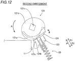
- the laser printer 200 configured such that a second friction pad holding member 124 rotates with respect to a first friction pad holding member 123 is described, unlike the first embodiment in which both the first friction pad holding member 23 and the second friction pad holding member 24 are configured to linearly move in the direction (direction P) in which the spring member 25 expands and contracts.
- a paper separation portion 102 of the laser printer 200 includes a pickup roller 121, a friction pad 22, the first friction pad holding member 123, the second friction pad holding member 124, and a spring member 25.
- the pickup roller 121 includes a first portion 121a that picks up stacked paper 150 while contacting with a surface of the paper 150 in a first state where the paper 150 is to be picked up by the first portion 121a and a second portion 121b that transports paper 151 picked up in the first state while contacting with a surface of the paper 151 in a second state where the picked up paper 151 is to be transported.
- the first portion 121a of the pickup roller 121 is configured to have a first curvature 1/R1 on a cross-sectional surface orthogonal to the rotation axis (shaft portion 121c) of the pickup roller 121, as shown in Fig. 11 .
- the second portion 121b of the pickup roller 121 is configured to have a second curvature 1/R2 on a cross-sectional surface orthogonal to the rotation axis of the pickup roller 121.
- the pickup roller 121 is configured such that the first curvature 1/R1 of the first portion 121a and the second curvature 1/R2 of the second portion 121b are different from each other.
- the pickup roller 121 is configured such that a contact area between the first portion 121a and the friction pad 22 in the first state and a contact area between the second portion 121b and the friction pad 22 in the second state are substantially equal to each other.
- the first curvature 1/R1 and the second curvature 1/R2 are set such that the contact area between the first portion 121a and the friction pad 22 in the first state and the contact area between the second portion 121b and the friction pad 22 in the second state are substantially equal to each other.
- the first friction pad holding member 123 includes a partition portion 123a arranged in a boundary area 25c between a first spring portion 25a and a second spring portion 25b of the spring member 25 and a fixing portion 123b that suppresses disengagement of the first spring portion 25a (spring member 25), as shown in Fig. 10 .
- the second friction pad holding member 124 includes a fixing portion 124a that suppresses disengagement of the second spring portion 25b (spring member 25).
- the second friction pad holding member 124 is configured to rotate with respect to the first friction pad holding member 123, as shown in Fig. 12 .
- the second friction pad holding member 124 is provided with a pair of convex portions 124b on both ends in a direction (direction X) in which the shaft portion 121c extends, as shown in Fig. 10 .
- the pair of convex portions 124b are formed to protrude in the direction in which the shaft portion 121c extends.
- the first friction pad holding member 123 is formed with hole portions 123c in positions corresponding to the convex portions 124b of the second friction pad holding member 124.
- the second friction pad holding member 124 is configured to be rotatable using the convex portions 124b as the center of rotation by fitting of the convex portions 124b into the hole portions 123c of the first friction pad holding member 123. Furthermore, the second friction pad holding member 124 is configured to be rotated toward the pickup roller 121 (in a direction P1) by the urging force of the second spring portion 25b (spring member 25) in a state where movement of the first friction pad holding member 123 is suppressed in the second state.
- the remaining structure of the second embodiment is similar to that of the aforementioned first embodiment.
- the pickup roller 121 is configured to be in surface contact such that the contact area between the first portion 121a of the pickup roller 121 and the friction pad 22 in the first state and the contact area between the second portion 121b of the pickup roller 121 and the friction pad 22 in the second state are substantially equal to each other.
- the second portion 121b is urged to the friction pad 22 in a state where the contact area between the friction pad 22 and the second portion 121b in the second state is substantially equal to the contact area between the friction pad 22 and the first portion 121a in the first state, unlike the case where the second portion 121b is urged (pushed) to the friction pad 22 in a state where the contact area between the friction pad 22 and the second portion 121b is smaller in the second state.
- an increase in pressure applied to the friction pad 22 can be suppressed in the second state, and hence tendency to wear and damage the friction pad 22 can be suppressed.
- the second friction pad holding member 124 is configured to rotate with respect to the first friction pad holding member 123, and the pickup roller 121 is configured such that the first curvature of the first portion 121a and the second curvature of the second portion 121b are different from each other.
- the friction pad 22 can be urged while a space for moving the second friction pad holding member 124 with respect to the first friction pad holding member 123 is further reduced, as compared with the case where the second friction pad holding member 124 is linearly moved with respect to the first friction pad holding member 123 in the direction in which the spring member 25 expands and contracts, and hence a space where the second friction pad holding member 124 is arranged can be reduced (can be compact).
- the present invention is not restricted to this.
- the present invention is also applicable to an ink-jet printer or the like other than the laser printer or another image forming apparatus such as a facsimile.
- the present invention is not restricted to this. According to the present invention, two urging members in which the first urging portion and the second urging portion are provided separately from each other may be provided.
- the present invention is not restricted to this. According to the present invention, an urging member other than the coil spring, such as a leaf spring, or an urging member other than a spring may be used.
- the present invention is not restricted to this. According to the present invention, the shaft portion 21c that is not eccentric as viewed along the rotation axis (shaft portion 21c) in the pickup roller may be provided in the pickup roller.
- first friction pad holding member and the second friction pad holding member separately from each other has been shown in each of the aforementioned first and second embodiments, the present invention is not restricted to this. According to the present invention, the first friction pad holding member and the second friction pad holding member may be integrally provided.
Landscapes
- Engineering & Computer Science (AREA)
- Mechanical Engineering (AREA)
- Sheets, Magazines, And Separation Thereof (AREA)
Abstract
This paper feeding apparatus (100) includes a pickup roller (21) including a first portion (21a) that picks up paper (150) in a first state where the paper is to be picked up and a second portion (21b) that transports, in a second state where the paper is to be transported, the paper picked up in the first state and a friction pad (22) that suppresses transport of paper subsequent to the picked up paper, and the pickup roller is in surface contact such that a contact area between the first portion and the friction pad and a contact area between the second portion and the friction pad are substantially equal to each other.
Description
- The present invention relates to a paper feeding apparatus and an image forming apparatus, and more particularly, it relates to a paper feeding apparatus and an image forming apparatus each including a pickup roller.
- A paper feeding apparatus including a pickup roller is known in general (refer to
Patent Document 1, for example). - In the
aforementioned Patent Document 1, there is disclosed a paper feeding apparatus including a rotatable pickup roller including a paper feed portion that picks up stacked paper while contacting with a surface of the stacked paper in a first state where the paper is to be picked up and a hub that contacts with the surface of the paper picked up in the first state in a second state where the paper is to be transported. This paper feeding apparatus includes a separation pad (friction pad) that is arranged to face the pickup roller and suppresses transport of subsequent paper by contacting with the paper subsequent to the paper picked up in the first state. The pickup roller is configured such that the paper feed portion is urged (pushed) to the separation pad in the first state and the hub is urged (pushed) to the separation pad in the second state. In this pickup roller, a portion of the hub that faces the separation pad has an area smaller than the area of a portion of the paper feed portion that faces the separation pad. - Patent Document 1: Japanese Patent No.
4385929 - In the paper feeding apparatus according to the
aforementioned Patent Document 1, however, the portion of the hub of the pickup roller that faces the separation pad has the area smaller than the area of the portion of the paper feed portion that faces the separation pad, and hence in the second state, the hub is urged (pushed) to the separation pad in a state where a contact area between the separation pad and the hub is small. Thus, the contact area between the separation pad and the hub is small in the second state, and hence pressure applied to the separation pad is large. Consequently, the separation pad easily becomes worn or damaged. - The present invention has been proposed in order to solve the aforementioned problem, and one object of the present invention is to provide a paper feeding apparatus and an image forming apparatus each capable of suppressing tendency to wear and damage a friction pad.
- A paper feeding apparatus according to a first aspect of the present invention includes a rotatable pickup roller including a first portion that picks up stacked paper while contacting with a surface of the paper in a first state where the paper is to be picked up and a second portion that transports the paper picked up in the first state while contacting with the surface of the paper in a second state where the paper is to be transported and a friction pad that is arranged to face the pickup roller and suppresses transport of paper subsequent to the paper picked up in the first state by contacting with the paper that is subsequent, and the pickup roller is in surface contact such that a contact area between the first portion and the friction pad in the first state and a contact area between the second portion and the friction pad in the second state are substantially equal to each other.
- In the paper feeding apparatus according to the first aspect of the present invention, as hereinabove described, the pickup roller is configured to be in surface contact such that the contact area between the first portion of the pickup roller and the friction pad in the first state and the contact area between the second portion of the pickup roller and the friction pad in the second state are substantially equal to each other. Thus, even when the friction pad is urged toward the pickup roller, the second portion is urged to the friction pad in a state where the contact area between the friction pad and the second portion in the second state is substantially equal to the contact area between the friction pad and the first portion in the first state, unlike the case where the second portion is urged (pushed) to the friction pad in a state where the contact area between the friction pad and the second portion is smaller in the second state. Thus, an increase in pressure applied to the friction pad can be suppressed in the second state, and hence tendency to wear and damage the friction pad can be suppressed.
- Preferably in the aforementioned paper feeding apparatus according to the first aspect, the first portion of the pickup roller has a first curvature on a cross-sectional surface orthogonal to the rotation axis of the pickup roller, the second portion of the pickup roller has a second curvature on the cross-sectional surface orthogonal to the rotation axis of the pickup roller, and the first curvature and the second curvature are set so as to bring the pickup roller into surface contact such that the contact area between the first portion and the friction pad in the first state and the contact area between the second portion and the friction pad in the second state are substantially equal to each other. According to this structure, the first curvature of the first portion and the second curvature of the second portion are adjusted, whereby surface contact between the friction pad and the first portion and surface contact between the friction pad and the second portion can be easily kept substantially the same as each other in the first state and the second state.
- Preferably, the aforementioned paper feeding apparatus according to the first aspect further includes a single urging member including a first urging portion and a second urging portion having urging force weaker than the urging force of the first urging portion, and the urging member urges the friction pad toward the pickup roller by the first urging portion in the first state and urges the friction pad toward the pickup roller by the second urging portion in the second state. According to this structure, the friction pad can be urged by the second urging portion having the urging force weaker than the urging force of the first urging portion in the second state, and hence the pressure applied to the friction pad can be further reduced in the second state than in the first state. Thus, tendency to wear the friction pad can be easily suppressed. Furthermore, the single (one) urging member can serve as both the first urging portion and the second urging portion having the urging force weaker than the urging force of the first urging portion, and hence the structure of the paper feeding apparatus can be simplified while an increase in the number of components can be suppressed, unlike the case where the first urging portion and the second urging portion are provided separately from each other.
- Preferably in the aforementioned structure in which the first portion has the first curvature, in the pickup roller, the center of curvature of the first portion and the center of curvature of the second portion are arranged in different positions, as viewed along the axis. According to this structure, the first curvature of the first portion and the second curvature of the second portion can be adjusted individually. Consequently, the surface contact between the friction pad and the first portion and the surface contact between the friction pad and the second portion can be more easily kept substantially the same as each other in the first state and the second state.
- Preferably in the aforementioned structure in which the center of curvature of the first portion and the center of curvature of the second portion are arranged in the different positions, the amount of protrusion of the pickup roller toward the friction pad is larger in the first state than in the second state. According to this structure, the position of the first portion in the first state can be further moved in a direction toward the friction pad than the position in the second state, and the position of the first portion in the second state can be further moved in a direction away from the friction pad than the position in the first state. Consequently, the paper can be easily picked up in the first state, and the paper can be transported while an increase in the pressure applied to the friction pad is suppressed in the second state.
- Preferably in the aforementioned structure in which the amount of protrusion of the pickup roller toward the friction pad is larger in the first state than in the second state, in the pickup roller, the center of curvature of the second portion is arranged closer to the second portion than the center of the pickup roller, and the center of curvature of the first portion is arranged closer to the first portion than the center of the pickup roller, as viewed along the axis, and in the pickup roller, the center of curvature of the second portion coincides with the rotation axis of the pickup roller. According to this structure, by the simple structure, the position of the first portion in the first state can be further moved in the direction toward the friction pad than the position in the second state, and the position of the first portion in the second state can be further moved in the direction away from the friction pad than the position in the first state.
- Preferably in the aforementioned structure in which the first portion has the first curvature, in the pickup roller, a surface of the first portion having the first curvature and a surface of the second portion having the second curvature are flush with each other. According to this structure, the pickup roller can be smoothly rotated when the paper is picked up and then transported.
- Preferably in this case, the paper feeding apparatus further includes a first friction pad holding member and a second friction pad holding member that hold the friction pad, the first friction pad holding member is arranged to partition a boundary region between the first urging portion and the second urging portion of the urging member, and the second friction pad holding member is arranged to hold the second urging portion between the first friction pad holding member and the second friction pad holding member. According to this structure, the second friction pad holding member (friction pad) can be urged by the second urging portion in a state where application of the urging force of the first urging portion is suppressed in the second state even when the common urging member including the first urging portion and the second urging portion is provided.
- Preferably in the aforementioned structure including the first friction pad holding member and the second friction pad holding member, the first friction pad holding member includes a plate-like partition portion, and the partition portion is held between the first urging portion and the second urging portion. According to this structure, the second friction pad holding member (friction pad) can be urged by the second urging portion while the application of the urging force of the first urging portion is stably suppressed by the partition portion in the second state even when the common urging member including the first urging portion and the second urging portion is provided.
- Preferably in the aforementioned structure including the partition portion, the partition portion includes an engaging portion that engages with the urging member. According to this structure, misalignment of the partition portion and the urging member can be suppressed.
- Preferably in the aforementioned structure including the first friction pad holding member and the second friction pad holding member, movement of the first friction pad holding member toward the pickup roller is restricted in the second state, and the second friction pad holding member is urged toward the pickup roller by urging of the second urging portion in a state where the movement of the first friction pad holding member is restricted in the second state. According to this structure, the movement of the first friction pad holding member toward the pickup roller is restricted in the second state so that the application of the urging force of the first urging portion can be suppressed, and hence the second friction pad holding member (friction pad) can be more easily urged by the second urging portion.
- Preferably in the aforementioned case where the movement of the first friction pad holding member toward the pickup roller is restricted in the second state, the first urging portion of the urging member is a first spring portion, the second urging portion of the urging member is a coil spring member that is a second spring portion, the first spring portion has a first pitch, and the second spring portion has a second pitch larger than the first pitch. According to this structure, the urging force can be easily changed by the single spring member, and hence by the simple structure, the movement of the first friction pad holding member toward the pickup roller is restricted in the second state so that the application of the urging force of the first urging portion can be suppressed.
- Preferably in the aforementioned structure including the first spring portion and the second spring portion, the second friction pad holding member is urged toward the pickup roller by urging of the second spring portion in a state where the first spring portion has a natural length such that the movement of the first friction pad holding member toward the pickup roller is restricted in the second state. According to this structure, generation of the urging force of the first spring portion to the first friction pad holding member can be prevented in the second state. Consequently, the movement of the first friction pad holding member toward the pickup roller is restricted so that the application of the urging force of the first urging portion can be easily suppressed.
- Preferably in the aforementioned case where the movement of the first friction pad holding member toward the pickup roller is restricted in the second state, the second friction pad holding member is movable relative to the first friction pad holding member. According to this structure, the second friction pad holding member can be easily moved independently of the first friction pad holding member in the second state. Thus, the movement of the first friction pad holding member toward the pickup roller is restricted in the second state so that the application of the urging force of the first urging portion can be further suppressed.
- Preferably in the aforementioned structure further including the first friction pad holding member and the second friction pad holding member, the first portion of the pickup roller has a first curvature, the second portion of the pickup roller has a second curvature, both the first friction pad holding member and the second friction pad holding member linearly move in a direction in which the urging member expands and contracts, and in the pickup roller, the first curvature of the first portion and the second curvature of the second portion are substantially equal to each other. According to this structure, the friction pad can be easily urged by the linear movement of the first friction pad holding member and the second friction pad holding member in the direction in which the urging member expands and contracts.
- Preferably in the aforementioned structure further including the first friction pad holding member and the second friction pad holding member, the first portion of the pickup roller has a first curvature, the second portion of the pickup roller has a second curvature, the second friction pad holding member rotates with respect to the first friction pad holding member, and in the pickup roller, the first curvature of the first portion and the second curvature of the second portion are different from each other. According to this structure, the friction pad can be urged while a space for moving the second friction pad holding member with respect to the first friction pad holding member is further reduced, as compared with the case where the second friction pad holding member is linearly moved with respect to the first friction pad holding member in the direction in which the urging member expands and contracts, and hence a space where the second friction pad holding member is arranged can be reduced (can be compact).
- Preferably in the aforementioned structure in which the first portion has the first curvature, the pickup roller has a shape formed by connecting a curve having the first curvature and a curve having the second curvature, as viewed along the axis. According to this structure, the contact area between the friction pad and the first portion in the first state and the contact area between the friction pad and the second portion in the second state can be easily made substantially equal to each other.
- Preferably in the aforementioned paper feeding apparatus according to the first aspect, the first portion of the pickup roller is detachable. According to this structure, only the first portion not the entire pickup roller can be replaced when it is necessary to replace the first portion.
- An image forming apparatus according to a second aspect of the present invention includes a printing portion that prints on paper, a rotatable pickup roller including a first portion that picks up the paper that is stacked while contacting with a surface of the paper in a first state where the paper is to be picked up and a second portion that transports the paper picked up in the first state while contacting with the surface of the paper in a second state where the paper is to be transported, and a friction pad that is arranged to face the pickup roller and suppresses transport of paper subsequent to the paper picked up in the first state by contacting with the paper that is subsequent, and the pickup roller is in surface contact such that a contact area between the first portion and the friction pad in the first state and a contact area between the second portion and the friction pad in the second state are substantially equal to each other.
- In the image forming apparatus according to the second aspect of the present invention, as hereinabove described, the pickup roller is configured to be in surface contact such that the contact area between the first portion of the pickup roller and the friction pad in the first state and the contact area between the second portion of the pickup roller and the friction pad in the second state are substantially equal to each other. Thus, even in the second state, the second portion is urged to the friction pad in a state where the contact area between the friction pad and the second portion is substantially equal to the contact area between the friction pad and the first portion in the first state, unlike the case where the second portion is urged (pushed) to the friction pad in a state where the contact area between the friction pad and the second portion is smaller in the second state. Thus, an increase in pressure applied to the friction pad can be suppressed in the second state, and hence tendency to wear and damage the friction pad can be suppressed.
- Preferably in the aforementioned paper feeding apparatus according to the first aspect, the first portion of the pickup roller has a first curvature on a cross-sectional surface orthogonal to the rotation axis of the pickup roller, the second portion of the pickup roller has a second curvature on the cross-sectional surface orthogonal to the rotation axis of the pickup roller, and the first curvature and the second curvature are set so as to bring the pickup roller into surface contact such that the contact area between the first portion and the friction pad in the first state and the contact area between the second portion and the friction pad in the second state are substantially equal to each other. According to this structure, the first curvature of the first portion and the second curvature of the second portion are adjusted, whereby surface contact between the friction pad and the first portion and surface contact between the friction pad and the second portion can be easily kept substantially the same as each other in the first state and the second state.
- According to the present invention, as hereinabove described, tendency to wear and damage the friction pad can be suppressed.
-
- [
Fig. 1 ] A schematic view showing the overall structure of a laser printer according to a first embodiment of the present invention. - [
Fig. 2 ] A perspective view showing a paper separation portion of the laser printer according to the first embodiment of the present invention. - [
Fig. 3 ] An enlarged view showing the paper separation portion of the laser printer according to the first embodiment of the present invention. - [
Fig. 4 ] A diagram of the paper separation portion of the laser printer according to the first embodiment of the present invention, as viewed from a side where a spring member is arranged. - [
Fig. 5 ] A diagram of a pickup roller of the laser printer according to the first embodiment of the present invention, as viewed along an axis. - [
Fig. 6 ] A diagram showing a first friction pad holding member and a second friction pad holding member in a first state of the laser printer according to the first embodiment of the present invention. - [
Fig. 7 ] A diagram showing the spring member in the first state of the laser printer according to the first embodiment of the present invention. - [
Fig. 8 ] A diagram showing the first friction pad holding member and the second friction pad holding member in a second state of the laser printer according to the first embodiment of the present invention. - [
Fig. 9 ] A diagram showing the spring member in the second state of the laser printer according to the first embodiment of the present invention. - [
Fig. 10 ] An enlarged view of a paper separation portion of a laser printer according to a second embodiment of the present invention. - [
Fig. 11 ] A diagram of a pickup roller of the laser printer according to the second embodiment of the present invention, as viewed along an axis. - [
Fig. 12 ] A diagram showing a first friction pad holding member and a second friction pad holding member in a first state of the laser printer according to the second embodiment of the present invention. - Embodiments of the present invention are hereinafter described on the basis of the drawings.
- The structure of a
laser printer 100 according to a first embodiment of the present invention is described with reference toFigs. 1 to 9 . Thelaser printer 100 is an example of the "paper feeding apparatus" or the "image forming apparatus" in the present invention. - The
laser printer 100 includes apaper feed tray 1 into whichpaper 150 is loaded, apaper separation portion 2 configured to separate thestacked paper 150 from thepaper feed tray 1 and transport the same,transport roller members paper 150 to a printing position, and paperdischarge roller members 5a to 5c configured to discharge the printedpaper 150 to a paper discharge tray 6, as shown inFig. 1 . Thetransport roller members discharge roller members 5a to 5c are respectively provided in pairs. Thelaser printer 100 includes a developing device 7 that prints on transportedpaper 151 and alaser emitting portion 8 configured to apply laser light to aphotoreceptor drum 70 of the developing device 7. Thelaser printer 100 includes a heating roller member 9 and a pressurizingroller member 10 configured to fix toner adhering to the transportedpaper 151. Thepaper feed tray 1 is provided with a push-upplate 11 configured to place thepaper 150 to a prescribed height with respect to thepaper separation portion 2. Thepaper separation portion 2 is configured to separate and pick up the stackedpaper 150 from thepaper feed tray 1 in a first state (seeFig. 6 ) described later, as shown inFig. 2 . Furthermore, thepaper separation portion 2 is configured to transport, in a second state (seeFig. 8 ) described later, thepaper 151 picked up from thepaper feed tray 1 in the first state. - According to the first embodiment, the
paper separation portion 2 includes apickup roller 21, afriction pad 22, a first frictionpad holding member 23, a second frictionpad holding member 24, and aspring member 25, as shown inFigs. 3 and4 . Thepaper separation portion 2 is set on a set portion 26 (seeFig. 1 ). - The
pickup roller 21 is configured to pick up (extract) the stackedpaper 150 from thepaper feed tray 1 and transport the same toward the developing device 7 (transport roller 4). Thepickup roller 21 includes afirst portion 21a that picks up thepaper 150 while contacting with a surface of thestacked paper 150 in the first state (seeFig. 6 ) where thepaper 150 is to be picked up and asecond portion 21b that transports the paper picked up in the first state while contacting with a surface of thepaper 151 in the second state (seeFig. 8 ) where the picked uppaper 151 is to be transported, as shown inFig. 3 . Thepickup roller 21 includes ashaft portion 21c and is set in ahousing 100a (seeFig. 1 ) to be rotatable. Theshaft portion 21c is arranged in thesecond portion 21b in a state where theshaft portion 21c is eccentric from the center C of thepickup roller 21 when thepickup roller 21 is taken as a whole, as shown inFig. 5 . Thefirst portion 21a and thesecond portion 21b are made of rubber (EPDM (ethylene-propylene rubber), for example) having a non-slip function. Thesecond portion 21b forms a main body portion of thepickup roller 21. Thefirst portion 21a is configured to be detachably (replaceably) fixed to thesecond portion 21b. Thepickup roller 21 is configured to operate and pick up thepaper 150 from thepaper feed tray 1 when the developing device 7 performs printing. - The
first portion 21a of thepickup roller 21 has afirst curvature 1/R on a cross-sectional surface orthogonal to the rotation axis (shaft portion 21c) of thepickup roller 21, as shown inFig. 5 . Thesecond portion 21b of thepickup roller 21 has asecond curvature 1/R on a cross-sectional surface orthogonal to the rotation axis of thepickup roller 21. More specifically, thepickup roller 21 is configured such that thefirst curvature 1/R of thefirst portion 21a and thesecond curvature 1/R of thesecond portion 21b are substantially equal to each other. Thepickup roller 21 is formed asymmetrically, as viewed along the rotation axis (shaft portion 21c). Thepickup roller 21 has a substantially circular shape (a near-circular shape) as a whole, as viewed along the axis. Thefirst portion 21a and thesecond portion 21b are configured such that the center C1 of curvature of thefirst portion 21a and the center C2 of curvature of thesecond portion 21b are located in different positions. The rotation center of theshaft portion 21c is arranged to coincide with the center C2 of thesecond portion 21b. Thepickup roller 21 is configured such that a surface of thefirst portion 21a having thefirst curvature 1/R and a surface of thesecond portion 21b having thesecond curvature 1/R are flush with each other. Thepickup roller 21 is configured such that the center C2 of curvature of thesecond portion 21b is arranged closer to thesecond portion 21b than the center C (geometric center C) of thepickup roller 21 and the center C1 of curvature of thefirst portion 21a is arranged closer to thefirst portion 21a than the center C of thepickup roller 21, as viewed along the axis. Furthermore, thepickup roller 21 is configured such that the center C2 of curvature of thesecond portion 21b is eccentric from the center C of thepickup roller 21 and coincides with the rotation axis of thepickup roller 21. Moreover, thepickup roller 21 is configured such that the amount of protrusion toward thefriction pad 22 is larger in the first state than in the second state. More specifically, a distance from the rotation axis (the center C2 of curvature) of thepickup roller 21 to thefriction pad 22 is D2 in the second state, as shown inFig. 8 . As shown inFig. 7 , a distance from the rotation axis of thepickup roller 21 to thefriction pad 22 is D1 larger than D2 in the first state. - The
friction pad 22 is arranged to face thepickup roller 21 and is configured to suppress transport ofpaper 152 subsequent to thepaper 151 picked up in the first state by contacting with thesubsequent paper 152, as shown inFig. 8 . Thefriction pad 22 is made of rubber (EPDM (ethylene-propylene rubber), for example) having a non-slip function. Thepickup roller 21 is configured such that a contact area between thefirst portion 21a and thefriction pad 22 in the first state and a contact area between thesecond portion 21b and thefriction pad 22 in the second state are substantially equal to each other, as shown inFigs. 6 to 9 . Specifically, in thepickup roller 21, thefirst curvature 1/R and thesecond curvature 1/R (seeFig. 5 ) are set such that the contact area between thefirst portion 21a and thefriction pad 22 in the first state and the contact area between thesecond portion 21b and thefriction pad 22 in the second state are substantially equal to each other. Thefriction pad 22 is in a substantially arcuate shape corresponding to the shape of each of thefirst portion 21a and thesecond portion 21b of thepickup roller 21, as viewed along the rotation axis (shaft portion 21c). Thefriction pad 22 and thefirst portion 21a or thesecond portion 21b of thepickup roller 21 are configured to be in surface contact with each other. Thefriction pad 22 has substantially the same width W as thefirst portion 21a of thepickup roller 21 in a direction (direction X) in which theshaft portion 21c extends, as shown inFig. 4 . - As shown in
Fig. 8 , thepickup roller 21 is configured such that the contact area between thefirst portion 21a and thefriction pad 22 in the first state and the contact area between thesecond portion 21b and thefriction pad 22 in the second state are substantially equal to each other in a state where thefriction pad 22 and thefirst portion 21a or thesecond portion 21b of thepickup roller 21 are arranged through the transportedpaper 151. In other words, thepickup roller 21 is configured such that the contact area between thefirst portion 21a and thefriction pad 22 in the first state and the contact area between thesecond portion 21b and thefriction pad 22 in the second state are substantially equal to each other in a state where the transportedpaper 151 is held between thefriction pad 22 and thefirst portion 21a or thesecond portion 21b of thepickup roller 21. - According to the first embodiment, the first friction
pad holding member 23 and the second frictionpad holding member 24 are configured to hold thefriction pad 22, as shown inFig. 3 . Specifically, the first frictionpad holding member 23 is configured to hold the second frictionpad holding member 24 to which thefriction pad 22 is fixed. Thefriction pad 22 is configured to be detachably fixed to the second frictionpad holding member 24. - Both the first friction
pad holding member 23 and the second frictionpad holding member 24 are configured to linearly move (move parallel) in a direction (direction P) in which thespring member 25 expands and contracts, as shown inFig. 3 . The second frictionpad holding member 24 is configured to be movable relative to the first frictionpad holding member 23. The first frictionpad holding member 23 is arranged to partition aboundary region 25c between afirst spring portion 25a and asecond spring portion 25b of thespring member 25, as shown inFigs. 3 and4 . Specifically, apartition portion 23a provided in the first frictionpad holding member 23 that extends in a direction (direction X) substantially orthogonal to the direction (direction P) in which thespring member 25 expands and contracts is arranged in theboundary region 25c between thefirst spring portion 25a and thesecond spring portion 25b of thespring member 25. Thepartition portion 23a is plate-like. Thepartition portion 23a has a thickness smaller than a pitch in the vicinity of theboundary region 25c of thespring member 25. Thepartition portion 23a is configured to be held between thefirst spring portion 25a and thesecond spring portion 25b. The first friction pad holding member 23 (partition portion 23a) includes a fixingportion 23b that suppresses disengagement of thefirst spring portion 25a (spring member 25). The fixingportion 23b is configured to protrude in a direction (direction P2) in which thefirst spring portion 25a expands or contracts. The fixingportion 23b is configured to suppress disengagement of thefirst spring portion 25a (spring member 25) from the first frictionpad holding member 23 by being fitted into an inner diameter portion of thefirst spring portion 25a (spring member 25). More specifically, the fixingportion 23b serves as an engaging portion that engages with thefirst spring portion 25a (spring member 25). - The second friction
pad holding member 24 is arranged to hold thesecond spring portion 25b between the second frictionpad holding member 24 and the first frictionpad holding member 23, as shown inFigs. 3 and4 . The second frictionpad holding member 24 includes a fixingportion 24a that suppresses disengagement of thesecond spring portion 25b (spring member 25). The fixingportion 24a is configured to protrude in the direction (direction P2) in which thefirst spring portion 25a expands or contracts. The fixingportion 24a is configured to suppress disengagement of thesecond spring portion 25b (spring member 25) from the second frictionpad holding member 24 by being fitted into an inner diameter portion of thesecond spring portion 25b (spring member 25). - According to the first embodiment, the first friction
pad holding member 23 is configured such that movement of the first frictionpad holding member 23 toward the pickup roller 21 (in a direction P1) is restricted in the second state, as shown inFigs. 8 and 9 . Specifically, the first frictionpad holding member 23 is configured to be movable in the direction in which thespring member 25 expands and contracts in the first state (a state where thepaper 151 is arranged between thefirst portion 21a and the friction pad 22). Furthermore, the first frictionpad holding member 23 is configured such that the set portion 26 (seeFig. 2 ) restricts the movement of the first frictionpad holding member 23 in the direction (toward the pickup roller 21 (in the direction P1)) in which thespring member 25 expands or contracts in the second state (a state where thepaper 151 picked up in the first state is to be transported and thepaper 152 subsequent to the picked uppaper 151 is to be not transported). The second frictionpad holding member 24 is configured to be urged toward thepickup roller 21 by urging of thesecond spring portion 25b (spring member 25) in a state where the movement of the first frictionpad holding member 23 is restricted in the second state. The first frictionpad holding member 23 and the second frictionpad holding member 24 are made of resin. - According to the first embodiment, the
spring member 25 includes a coil spring, for example. Thespring member 25 includes a single spring member including thefirst spring portion 25a and thesecond spring portion 25b having urging force weaker than the urging force of thefirst spring portion 25a, as shown inFig. 3 . Thespring member 25 includes thesecond spring portion 25b closer to the pickup roller 21 (in the direction P1) and thefirst spring portion 25a opposite to the pickup roller 21 (in the direction P2). Thefirst spring portion 25a having a natural length has a first pitch smaller than a second pitch of thesecond spring portion 25b having a natural length. Thespring member 25 is configured to urge thefriction pad 22 toward thepickup roller 21 by thefirst spring portion 25a in the first state and to urge thefriction pad 22 toward thepickup roller 21 by thesecond spring portion 25b in the second state. Thespring member 25 is configured such that thefirst spring portion 25a has a natural length in the second state. More specifically, thefriction pad 22 is urged toward thepickup roller 21 by the urging force of thesecond spring portion 25b in the second state. In other words, the second frictionpad holding member 24 is configured to be urged toward thepickup roller 21 by urging of thesecond spring portion 25b in a state where thefirst spring portion 25a has a natural length such that the movement of the first frictionpad holding member 23 toward thepickup roller 21 is restricted in the second state. Thespring member 25 is an example of the "urging member" in the present invention. Thefirst spring portion 25a is an example of the "first urging portion" in the present invention. Thesecond spring portion 25b is an example of the "second urging portion" in the present invention. - The developing device 7 includes the
photoreceptor drum 70 configured to perform printing by causing toner to adhere to the transportedpaper 151, a developingroller 71 configured to supply the toner to thephotoreceptor drum 70, asupply roller 72 configured to supply the toner to the developingroller 71, and a restrictingroller 73, as shown inFig. 1 . All of the developingroller 71, thesupply roller 72, and the restrictingroller 73 are arranged in atoner carrying region 74. The developing device 7 is an example of the "printing portion" in the present invention. - The developing device 7 also includes a
toner supply passage 75 that supplies the toner to thetoner carrying region 74, atoner cartridge 76 that stores new toner, and an oldtoner recovery portion 77 configured to recover old toner adhering to the developingroller 71 or old toner around the developingroller 71. The developing device 7 further includes atransfer roller 78 arranged in a position that faces thephotoreceptor drum 70, configured to transfer the toner adhering to thephotoreceptor drum 70 to the transportedpaper 151, and a cleaningportion 79 configured to recover toner remaining on thephotoreceptor drum 70. - The
photoreceptor drum 70 is configured such that a surface thereof is negatively charged. In thephotoreceptor drum 70 during printing, thelaser emitting portion 8 first applies laser light to a prescribed surface of thephotoreceptor drum 70 along the rotational direction of thephotoreceptor drum 70, and negative charge is removed from a surface of a position subjected to the application of the laser light. Thus, an electrostatic latent image is formed on a region of the surface of thephotoreceptor drum 70 from which the negative charge is removed. Thereafter, the toner supplied by the developingroller 71 adheres to the electrostatic latent image formed on thephotoreceptor drum 70. Then, the positively chargedtransfer roller 78 moves the negatively charged toner from thephotoreceptor drum 70 toward thetransfer roller 78, whereby the toner is adsorbed (transferred) to thepaper 151 transported between thetransfer roller 78 and thephotoreceptor drum 70. Consequently, an image is printed on the transportedpaper 151 on the basis of the electrostatic latent image formed on thephotoreceptor drum 70. - After the negative charge is removed from the surface of the
photoreceptor drum 70, the cleaningportion 79 recovers toner remaining on the surface of thephotoreceptor drum 70. Finally, an unshown electrode negatively charges the surface of thephotoreceptor drum 70 again, so that a printing operation is performed again. - The operation of the
paper separation portion 2 for separating thestacked paper 150 from thepaper feed tray 1 and transporting the same is now described with reference toFigs. 6 to 9 .Figs. 6 and8 omit the setportion 26 for the convenience of illustration and show thepaper separation portion 2 viewed along the rotation axis (shaft portion 21c).Figs. 7 and9 omit the setportion 26 and the first frictionpad holding member 23 for the convenience of illustration and show thepaper separation portion 2 viewed along the rotation axis (shaft portion 21c). - A state where the
paper 150 stacked on thepaper feed tray 1 is picked up (extracted) in the first state is described with reference toFigs. 6 and 7 . First, thepickup roller 21 is rotated in a direction A, whereby thepaper 150 stacked on thepaper feed tray 1 is held between thefirst portion 21a and thefriction pad 22. Thereafter, the spring member 25 (thefirst spring portion 25a and thesecond spring portion 25b) is urged opposite to the pickup roller 21 (in the direction P2) until anend 21e of thepickup roller 21 is rotated to a position corresponding to thespring member 25. Thefirst spring portion 25a and thesecond spring portion 25b urge thefriction pad 22 toward thepickup roller 21, whereby thepickup roller 21 is rotated in the direction A in a state where the paper is held between thefirst portion 21a and thefriction pad 22. Then, thepickup roller 21 is further rotated in the direction A, whereby a state where theend 21e of thepickup roller 21 is arranged in the position corresponding to thespring member 25 is shifted to the second state. - A state where the
paper 151 picked up (extracted) in the first state is transported toward the developing device 7 in the second state is described with reference toFigs. 8 and 9 . From the state where theend 21e of thepickup roller 21 is arranged in the position corresponding to thespring member 25, thepickup roller 21 is rotated in the direction A, whereby thepaper 151 between thefirst portion 21a and thefriction pad 22 is transported. At this time, thepickup roller 21 is arranged in a position above (in the direction P1) the position in the first state by theeccentric shaft portion 21c. In the second state, the movement of the first frictionpad holding member 23 toward the pickup roller 21 (in the direction P1) is restricted, so that thefriction pad 22 is urged toward thepickup roller 21 by thesecond spring portion 25b of thespring member 25. Thus, in the second state, thefriction pad 22 is urged toward thepickup roller 21 by urging force weaker than urging force (force of holding the paper 150) in the first state, and hence thepaper 151 can be transported toward the developing device 7 (transport roller member 4) while the transport of thepaper 152 other than the transported paper 151 (simultaneous transport (multi feed) of thepaper 151 and the paper 152) is suppressed. - According to the first embodiment, as hereinabove described, the
pickup roller 21 is configured to be in surface contact such that the contact area between thefirst portion 21a of thepickup roller 21 and thefriction pad 22 in the first state and the contact area between thesecond portion 21b of thepickup roller 21 and thefriction pad 22 in the second state are substantially equal to each other. Thus, even when thefriction pad 22 is urged toward thepickup roller 21, thesecond portion 21b is urged to thefriction pad 22 in a state where the contact area between thefriction pad 22 and thesecond portion 21b in the second state is substantially equal to the contact area between thefriction pad 22 and thefirst portion 21a in the first state, unlike the case where thesecond portion 21b is urged (pushed) to thefriction pad 22 in a state where the contact area between thefriction pad 22 and thesecond portion 21b is smaller in the second state. Thus, an increase in pressure applied to thefriction pad 22 can be suppressed in the second state, and hence tendency to wear and damage thefriction pad 22 can be suppressed. - According to the first embodiment, as hereinabove described, the
first portion 21a of thepickup roller 21 is configured to have the first curvature on the cross-sectional surface orthogonal to the rotation axis of thepickup roller 21, thesecond portion 21b of thepickup roller 21 is configured to have the second curvature on the cross-sectional surface orthogonal to the rotation axis of thepickup roller 21, and the first curvature and the second curvature are set so as to bring thepickup roller 21 into surface contact such that the contact area between thefirst portion 21a and thefriction pad 22 in the first state and the contact area between thesecond portion 21b and thefriction pad 22 in the second state are substantially equal to each other. Thus, surface contact between thefriction pad 22 and thefirst portion 21a and surface contact between thefriction pad 22 and thesecond portion 21b can be easily kept substantially the same as each other in the first state and the second state. - According to the first embodiment, as hereinabove described, the
single spring member 25 including thefirst spring portion 25a and thesecond spring portion 25b having the urging force weaker than the urging force of thefirst spring portion 25a is provided, and thespring member 25 is configured to urge thefriction pad 22 toward thepickup roller 21 by thefirst spring portion 25a in the first state and to urge thefriction pad 22 toward thepickup roller 21 by thesecond spring portion 25b in the second state. Thus, thefriction pad 22 can be urged by thesecond spring portion 25b having the urging force weaker than the urging force of thefirst spring portion 25a in the second state, and hence the pressure applied to thefriction pad 22 can be further reduced in the second state than in the first state. Thus, tendency to wear thefriction pad 22 can be easily suppressed. Furthermore, the single (one)spring member 25 can serve as both thefirst spring portion 25a and thesecond spring portion 25b having the urging force weaker than the urging force of thefirst spring portion 25a, and hence the structure of thelaser printer 100 can be simplified while an increase in the number of components can be suppressed, unlike the case where thefirst spring portion 25a and thesecond spring portion 25b are provided separately from each other. - According to the first embodiment, as hereinabove described, the
pickup roller 21 is configured such that the center C1 of curvature of thefirst portion 21a and the center C2 of curvature of thesecond portion 21b are located in the different positions. Thus, thefirst curvature 1/R of thefirst portion 21a and thesecond curvature 1/R of thesecond portion 21b can be adjusted individually. Consequently, the surface contact between thefriction pad 22 and thefirst portion 21a and the surface contact between thefriction pad 22 and thesecond portion 21b can be more easily kept substantially the same as each other in the first state and the second state. - According to the first embodiment, as hereinabove described, the
pickup roller 21 is configured such that the amount of protrusion toward thefriction pad 22 is larger in the first state than in the second state. Thus, the position of thefirst portion 21a in the first state can be further moved in a direction toward thefriction pad 22 than the position in the second state, and the position of thefirst portion 21a in the second state can be further moved in a direction away from thefriction pad 22 than the position in the first state. Consequently, thepaper 150 can be easily picked up in the first state, and thepaper 22 can be transported while an increase in the pressure applied to thefriction pad 22 is suppressed in the second state. - According to the first embodiment, as hereinabove described, the
pickup roller 21 is configured such that the center C2 of curvature of thesecond portion 21b is arranged closer to thesecond portion 21b than the center C of thepickup roller 21 and the center C1 of curvature of thefirst portion 21a is arranged closer to thefirst portion 21a than the center C of thepickup roller 21. Furthermore, thepickup roller 21 is configured such that the center C2 of curvature of thesecond portion 21b coincides with the rotation axis of thepickup roller 21. Thus, by the simple structure, the position of thefirst portion 21a in the first state can be further moved in the direction toward thefriction pad 22 than the position in the second state, and the position of thefirst portion 21a in the second state can be further moved in the direction away from thefriction pad 22 than the position in the first state. - According to the first embodiment, as hereinabove described, the
pickup roller 21 is configured such that the surface of thefirst portion 21a having thefirst curvature 1/R and the surface of thesecond portion 21b having thesecond curvature 1/R are flush with each other. Thus, thepickup roller 21 can be smoothly rotated when thepaper 150 is picked up and then transported. - According to the first embodiment, as hereinabove described, the first friction
pad holding member 23 and the second frictionpad holding member 24 that hold thefriction pad 22 are provided, the first frictionpad holding member 23 is arranged to partition the boundary region between thefirst spring portion 25a and thesecond spring portion 25b of thespring member 25, and the second frictionpad holding member 24 is arranged to hold thesecond spring portion 25b between thefirst friction pad 22 holding member and the second frictionpad holding member 24. Thus, the second friction pad holding member 24 (friction pad 22) can be urged by thesecond spring portion 25b in a state where application of the urging force of thefirst spring portion 25a is suppressed in the second state even when thecommon spring member 25 including thefirst spring portion 25a and thesecond spring portion 25b is provided. - According to the first embodiment, as hereinabove described, the plate-
like partition portion 23a is configured to be held between thefirst spring portion 25a and thesecond spring portion 25b. Thus, the second frictionpad holding member 24 can be urged by thesecond spring portion 25b while the application of the urging force of thefirst spring portion 25a is stably suppressed by thepartition portion 23a in the second state. - According to the first embodiment, as hereinabove described, the
partition portion 23a is configured to include the fixingportion 23b serving as the engaging portion that engages with thefirst spring portion 25a. Thus, misalignment of thepartition portion 23a and thefirst spring portion 25a can be suppressed. - According to the first embodiment, as hereinabove described, the first friction
pad holding member 23 is configured such that the movement of the first frictionpad holding member 23 toward thepickup roller 21 is restricted in the second state, and the second frictionpad holding member 24 is configured to be urged toward thepickup roller 21 by the urging of thesecond spring portion 25b in the state where the movement of the first frictionpad holding member 23 is restricted in the second state. Thus, the movement of the first frictionpad holding member 23 toward thepickup roller 21 is restricted in the second state so that the application of the urging force of thefirst spring portion 25a can be suppressed, and hence the second friction pad holding member 24 (friction pad 22) can be more easily urged by thesecond spring portion 25b. - According to the first embodiment, as hereinabove described, the
second spring portion 25b is configured to have the second pitch larger than the first pitch of thefirst spring portion 25a. Thus, the urging force can be easily changed by thesingle spring member 25, and hence by the simple structure, the movement of the first frictionpad holding member 23 toward thepickup roller 21 is restricted in the second state so that the application of the urging force of thefirst spring portion 25a can be suppressed. - According to the first embodiment, as hereinabove described, the second friction
pad holding member 24 is configured to be urged toward thepickup roller 21 by the urging of thesecond spring portion 25b in the state where thefirst spring portion 25a has a natural length such that the movement of the first frictionpad holding member 23 toward thepickup roller 21 is restricted in the second state. Thus, generation of the urging force of thefirst spring portion 25a to the first frictionpad holding member 23 can be prevented in the second state. Consequently, the movement of the first frictionpad holding member 23 toward thepickup roller 21 is restricted so that the application of the urging force of thefirst spring portion 25a can be easily suppressed. - According to the first embodiment, as hereinabove described, the second friction
pad holding member 24 is configured to be movable relative to the first frictionpad holding member 23. Thus, the second frictionpad holding member 24 can be easily moved independently of the first frictionpad holding member 23 in the second state. - According to the first embodiment, as hereinabove described, the first friction
pad holding member 23 and the second frictionpad holding member 24 are configured to linearly move in the direction in which thespring member 25 expands and contracts, and thepickup roller 21 is configured such that the first curvature of thefirst portion 21a and the second curvature of thesecond portion 21b are substantially equal to each other. Thus, thefriction pad 22 can be easily urged by the linear movement of the first frictionpad holding member 23 and the second frictionpad holding member 24 in the direction in which thespring member 25 expands and contracts. - According to the first embodiment, as hereinabove described, the
pickup roller 21 is configured to have a shape formed by connecting a curve having thefirst curvature 1/R and a curve having thesecond curvature 1/R. Thus, the contact area between thefriction pad 22 and thefirst portion 21a in the first state and the contact area between thefriction pad 22 and thesecond portion 21b in the second state can be easily made substantially equal to each other. - According to the first embodiment, as hereinabove described, the
pickup roller 21 is configured such that thefirst portion 21a is detachable. Thus, only thefirst portion 21a not theentire pickup roller 21 can be replaced when it is necessary to replace thefirst portion 21a. - The structure of a
laser printer 200 according to a second embodiment of the present invention is now described with reference toFigs. 10 to 12 . Thelaser printer 200 is an example of the "paper feeding apparatus" or the "image forming apparatus" in the present invention. - In this second embodiment, the
laser printer 200 configured such that a second frictionpad holding member 124 rotates with respect to a first frictionpad holding member 123 is described, unlike the first embodiment in which both the first frictionpad holding member 23 and the second frictionpad holding member 24 are configured to linearly move in the direction (direction P) in which thespring member 25 expands and contracts. - As shown in
Fig. 10 , apaper separation portion 102 of thelaser printer 200 according to the second embodiment includes apickup roller 121, afriction pad 22, the first frictionpad holding member 123, the second frictionpad holding member 124, and aspring member 25. - According to the second embodiment, the
pickup roller 121 includes afirst portion 121a that picks upstacked paper 150 while contacting with a surface of thepaper 150 in a first state where thepaper 150 is to be picked up by thefirst portion 121a and asecond portion 121b that transportspaper 151 picked up in the first state while contacting with a surface of thepaper 151 in a second state where the picked uppaper 151 is to be transported. - The
first portion 121a of thepickup roller 121 is configured to have afirst curvature 1/R1 on a cross-sectional surface orthogonal to the rotation axis (shaft portion 121c) of thepickup roller 121, as shown inFig. 11 . More specifically, thesecond portion 121b of thepickup roller 121 is configured to have asecond curvature 1/R2 on a cross-sectional surface orthogonal to the rotation axis of thepickup roller 121. More specifically, thepickup roller 121 is configured such that thefirst curvature 1/R1 of thefirst portion 121a and thesecond curvature 1/R2 of thesecond portion 121b are different from each other. Thepickup roller 121 is configured such that a contact area between thefirst portion 121a and thefriction pad 22 in the first state and a contact area between thesecond portion 121b and thefriction pad 22 in the second state are substantially equal to each other. Specifically, in thepickup roller 121, thefirst curvature 1/R1 and thesecond curvature 1/R2 are set such that the contact area between thefirst portion 121a and thefriction pad 22 in the first state and the contact area between thesecond portion 121b and thefriction pad 22 in the second state are substantially equal to each other. - The first friction
pad holding member 123 includes apartition portion 123a arranged in aboundary area 25c between afirst spring portion 25a and asecond spring portion 25b of thespring member 25 and a fixingportion 123b that suppresses disengagement of thefirst spring portion 25a (spring member 25), as shown inFig. 10 . The second frictionpad holding member 124 includes a fixingportion 124a that suppresses disengagement of thesecond spring portion 25b (spring member 25). - According to the second embodiment, the second friction
pad holding member 124 is configured to rotate with respect to the first frictionpad holding member 123, as shown inFig. 12 . Specifically, the second frictionpad holding member 124 is provided with a pair ofconvex portions 124b on both ends in a direction (direction X) in which theshaft portion 121c extends, as shown inFig. 10 . The pair ofconvex portions 124b are formed to protrude in the direction in which theshaft portion 121c extends. The first frictionpad holding member 123 is formed withhole portions 123c in positions corresponding to theconvex portions 124b of the second frictionpad holding member 124. The second frictionpad holding member 124 is configured to be rotatable using theconvex portions 124b as the center of rotation by fitting of theconvex portions 124b into thehole portions 123c of the first frictionpad holding member 123. Furthermore, the second frictionpad holding member 124 is configured to be rotated toward the pickup roller 121 (in a direction P1) by the urging force of thesecond spring portion 25b (spring member 25) in a state where movement of the first frictionpad holding member 123 is suppressed in the second state. - The remaining structure of the second embodiment is similar to that of the aforementioned first embodiment.
- According to the second embodiment, as hereinabove described, the
pickup roller 121 is configured to be in surface contact such that the contact area between thefirst portion 121a of thepickup roller 121 and thefriction pad 22 in the first state and the contact area between thesecond portion 121b of thepickup roller 121 and thefriction pad 22 in the second state are substantially equal to each other. Thus, even when thefriction pad 22 is urged toward thepickup roller 121, thesecond portion 121b is urged to thefriction pad 22 in a state where the contact area between thefriction pad 22 and thesecond portion 121b in the second state is substantially equal to the contact area between thefriction pad 22 and thefirst portion 121a in the first state, unlike the case where thesecond portion 121b is urged (pushed) to thefriction pad 22 in a state where the contact area between thefriction pad 22 and thesecond portion 121b is smaller in the second state. Thus, an increase in pressure applied to thefriction pad 22 can be suppressed in the second state, and hence tendency to wear and damage thefriction pad 22 can be suppressed. - According to the second embodiment, as hereinabove described, the second friction
pad holding member 124 is configured to rotate with respect to the first frictionpad holding member 123, and thepickup roller 121 is configured such that the first curvature of thefirst portion 121a and the second curvature of thesecond portion 121b are different from each other. Thus, thefriction pad 22 can be urged while a space for moving the second frictionpad holding member 124 with respect to the first frictionpad holding member 123 is further reduced, as compared with the case where the second frictionpad holding member 124 is linearly moved with respect to the first frictionpad holding member 123 in the direction in which thespring member 25 expands and contracts, and hence a space where the second frictionpad holding member 124 is arranged can be reduced (can be compact). - The remaining effects of the second embodiment are similar to those of the aforementioned first embodiment.
- The embodiments disclosed this time must be considered as illustrative in all points and not restrictive. The range of the present invention is shown not by the above description of the embodiments but by the scope of claims for patent, and all modifications within the meaning and range equivalent to the scope of claims for patent are further included.
- For example, while the example of applying the present invention to the laser printer as the example of the image forming apparatus has been shown in each of the aforementioned first and second embodiments, the present invention is not restricted to this. For example, the present invention is also applicable to an ink-jet printer or the like other than the laser printer or another image forming apparatus such as a facsimile.
- While the example of providing the single spring member 25 (urging member) including the
first spring portion 25a (first urging portion) and thesecond spring portion 25b (second urging portion) having the urging force weaker than the urging force of thefirst spring portion 25a has been shown in each of the aforementioned first and second embodiments, the present invention is not restricted to this. According to the present invention, two urging members in which the first urging portion and the second urging portion are provided separately from each other may be provided. - While the example of providing the spring member including the coil spring as the urging member according to the present invention has been shown in each of the aforementioned first and second embodiments, the present invention is not restricted to this. According to the present invention, an urging member other than the coil spring, such as a leaf spring, or an urging member other than a spring may be used.
- While the example of providing the
shaft portion 21c that is eccentric as viewed along the rotation axis (shaft portion 21c) in the pickup roller has been shown in each of the aforementioned first and second embodiments, the present invention is not restricted to this. According to the present invention, theshaft portion 21c that is not eccentric as viewed along the rotation axis (shaft portion 21c) in the pickup roller may be provided in the pickup roller. - While the example of forming the first friction pad holding member and the second friction pad holding member separately from each other has been shown in each of the aforementioned first and second embodiments, the present invention is not restricted to this. According to the present invention, the first friction pad holding member and the second friction pad holding member may be integrally provided.
-
- 7 developing device (printing portion)
- 21, 121 pickup roller
- 21a, 121a first portion
- 21b, 121b second portion
- 22 friction pad
- 23, 123 first friction pad holding member
- 23a partition portion
- 24, 124 second friction pad holding member
- 25 spring member (urging member)
- 25a first spring portion (first urging portion)
- 25b second spring portion (second urging portion)
- 25c boundary region
- 100, 200 laser printer (paper feeding apparatus, image forming apparatus)
Claims (20)
- A paper feeding apparatus (100, 200) comprising:a rotatable pickup roller (21, 121) including a first portion (21a, 121a) that picks up stacked paper (150) while contacting with a surface of the paper in a first state where the paper is to be picked up and a second portion (21b, 121b) that transports the paper picked up in the first state while contacting with the surface of the paper in a second state where the paper is to be transported; anda friction pad (22) that is arranged to face the pickup roller and suppresses transport of paper subsequent to the paper picked up in the first state by contacting with the paper that is subsequent, whereinthe pickup roller is in surface contact such that a contact area between the first portion and the friction pad in the first state and a contact area between the second portion and the friction pad in the second state are substantially equal to each other.
- The paper feeding apparatus according to claim 1, wherein
the first portion of the pickup roller has a first curvature on a cross-sectional surface orthogonal to a rotation axis of the pickup roller,
the second portion of the pickup roller has a second curvature on the cross-sectional surface orthogonal to the rotation axis of the pickup roller, and
the first curvature and the second curvature are set so as to bring the pickup roller into surface contact such that the contact area between the first portion and the friction pad in the first state and the contact area between the second portion and the friction pad in the second state are substantially equal to each other. - The paper feeding apparatus according to claim 1, further comprising a single urging member (25) including a first urging portion (25a) and a second urging portion (25b) having urging force weaker than urging force of the first urging portion, wherein
the urging member urges the friction pad toward the pickup roller by the first urging portion in the first state and urges the friction pad toward the pickup roller by the second urging portion in the second state. - The paper feeding apparatus according to claim 2, wherein
in the pickup roller, a center of curvature of the first portion and a center of curvature of the second portion are arranged in different positions, as viewed along the axis. - The paper feeding apparatus according to claim 4, wherein
an amount of protrusion of the pickup roller toward the friction pad is larger in the first state than in the second state. - The paper feeding apparatus according to claim 5, wherein
in the pickup roller, the center of curvature of the second portion is arranged closer to the second portion than a center of the pickup roller, and the center of curvature of the first portion is arranged closer to the first portion than the center of the pickup roller, as viewed along the axis, and
in the pickup roller, the center of curvature of the second portion coincides with the rotation axis of the pickup roller. - The paper feeding apparatus according to claim 2, wherein
in the pickup roller, a surface of the first portion having the first curvature and a surface of the second portion having the second curvature are flush with each other. - The paper feeding apparatus according to claim 3, further comprising a first friction pad holding member (23, 123) and a second friction pad holding member (24, 124) that hold the friction pad, wherein
the first friction pad holding member is arranged to partition a boundary region between the first urging portion and the second urging portion of the urging member, and
the second friction pad holding member is arranged to hold the second urging portion between the first friction pad holding member and the second friction pad holding member. - The paper feeding apparatus according to claim 8, wherein
the first friction pad holding member includes a plate-like partition portion (23a), and
the partition portion is held between the first urging portion and the second urging portion. - The paper feeding apparatus according to claim 9, wherein
the partition portion includes an engaging portion that engages with the urging member. - The paper feeding apparatus according to claim 8, wherein
movement of the first friction pad holding member toward the pickup roller is restricted in the second state, and
the second friction pad holding member is urged toward the pickup roller by urging of the second urging portion in a state where the movement of the first friction pad holding member is restricted in the second state. - The paper feeding apparatus according to claim 11, wherein
the first urging portion of the urging member is a first spring portion (25a), and the second urging portion of the urging member is a coil spring member (25) that is a second spring portion (25b),
the first spring portion has a first pitch, and
the second spring portion has a second pitch larger than the first pitch. - The paper feeding apparatus according to claim 12, wherein
the second friction pad holding member is urged toward the pickup roller by urging of the second spring portion in a state where the first spring portion has a natural length such that the movement of the first friction pad holding member toward the pickup roller is restricted in the second state. - The paper feeding apparatus according to claim 11, wherein
the second friction pad holding member is movable relative to the first friction pad holding member. - The paper feeding apparatus according to claim 14, wherein
the first portion of the pickup roller has a first curvature,
the second portion of the pickup roller has a second curvature,
both the first friction pad holding member and the second friction pad holding member linearly move in a direction in which the urging member expands and contracts, and
in the pickup roller, the first curvature of the first portion and the second curvature of the second portion are substantially equal to each other. - The paper feeding apparatus according to claim 14, wherein
the first portion of the pickup roller has a first curvature,
the second portion of the pickup roller has a second curvature,
the second friction pad holding member rotates with respect to the first friction pad holding member, and
in the pickup roller, the first curvature of the first portion and the second curvature of the second portion are different from each other. - The paper feeding apparatus according to claim 2, wherein
the pickup roller has a shape formed by connecting a curve having the first curvature and a curve having the second curvature, as viewed along the axis. - The paper feeding apparatus according to claim 1, wherein
the first portion of the pickup roller is detachable. - An image forming apparatus (100, 200) comprising:a printing portion (7) that prints on paper;a rotatable pickup roller including a first portion that picks up the paper that is stacked while contacting with a surface of the paper in a first state where the paper is to be picked up and a second portion that transports the paper picked up in the first state while contacting with the surface of the paper in a second state where the paper is to be transported; anda friction pad that is arranged to face the pickup roller and suppresses transport of paper subsequent to the paper picked up in the first state by contacting with the paper that is subsequent, whereinthe pickup roller is in surface contact such that a contact area between the first portion and the friction pad in the first state and a contact area between the second portion and the friction pad in the second state are substantially equal to each other.
- The image forming apparatus according to claim 19, wherein
the first portion of the pickup roller has a first curvature on a cross-sectional surface orthogonal to a rotation axis of the pickup roller,
the second portion of the pickup roller has a second curvature on the cross-sectional surface orthogonal to the rotation axis of the pickup roller, and
the first curvature and the second curvature are set so as to bring the pickup roller into surface contact such that the contact area between the first portion and the friction pad in the first state and the contact area between the second portion and the friction pad in the second state are substantially equal to each other.
Applications Claiming Priority (2)
| Application Number | Priority Date | Filing Date | Title |
|---|---|---|---|
| JP2013156370A JP2015024909A (en) | 2013-07-29 | 2013-07-29 | Paper feeding device and image formation device |
| PCT/JP2014/062243 WO2015015854A1 (en) | 2013-07-29 | 2014-05-07 | Paper feeding apparatus and image forming apparatus |
Publications (1)
| Publication Number | Publication Date |
|---|---|
| EP3028967A1 true EP3028967A1 (en) | 2016-06-08 |
Family
ID=52431401
Family Applications (1)
| Application Number | Title | Priority Date | Filing Date |
|---|---|---|---|
| EP14833067.3A Withdrawn EP3028967A1 (en) | 2013-07-29 | 2014-05-07 | Paper feeding apparatus and image forming apparatus |
Country Status (5)
| Country | Link |
|---|---|
| US (1) | US20160167903A1 (en) |
| EP (1) | EP3028967A1 (en) |
| JP (1) | JP2015024909A (en) |
| CN (1) | CN105408232A (en) |
| WO (1) | WO2015015854A1 (en) |
Families Citing this family (2)
| Publication number | Priority date | Publication date | Assignee | Title |
|---|---|---|---|---|
| KR102753994B1 (en) * | 2019-08-22 | 2025-01-10 | 엘지디스플레이 주식회사 | Display device |
| CN118790778A (en) * | 2024-09-14 | 2024-10-18 | 南通人民彩印有限公司 | A feeding device for paper color printing |
Family Cites Families (13)
| Publication number | Priority date | Publication date | Assignee | Title |
|---|---|---|---|---|
| JPH01111637U (en) * | 1988-01-22 | 1989-07-27 | ||
| JP2518810Y2 (en) * | 1990-08-09 | 1996-11-27 | 理想科学工業株式会社 | Paper feeder |
| JPH082723A (en) * | 1994-06-21 | 1996-01-09 | Canon Inc | Sheet feeding apparatus and image forming apparatus including the same |
| US6055407A (en) * | 1998-03-10 | 2000-04-25 | Canon Kabushiki Kaisha | Sheet feeding device and image forming apparatus having the sheet feeding device |
| JP2002104675A (en) * | 2000-09-29 | 2002-04-10 | Canon Inc | Sheet feeding device and image forming device |
| US6932529B2 (en) * | 2002-08-13 | 2005-08-23 | Hewlett-Packard Development Company, L.P. | Method and systems for accessing a separation pad in a printing device |
| US7614622B2 (en) * | 2004-07-27 | 2009-11-10 | Canon Kabushiki Kaisha | Sheet feeding apparatus and image forming apparatus |
| JP4312697B2 (en) * | 2004-10-28 | 2009-08-12 | 株式会社リコー | Paper feeding device and image forming apparatus |
| JP4385929B2 (en) | 2004-11-09 | 2009-12-16 | 船井電機株式会社 | Paper feeder |
| KR20070087712A (en) * | 2005-06-30 | 2007-08-29 | 삼성전자주식회사 | Paper feeder and paper pickup method, and image forming apparatus employing the same |
| JP2008133078A (en) * | 2006-11-28 | 2008-06-12 | Kyocera Mita Corp | Sheet feeder |
| JP2009120305A (en) * | 2007-11-13 | 2009-06-04 | Oki Electric Ind Co Ltd | Wear detection device |
| KR101521076B1 (en) * | 2008-12-19 | 2015-05-18 | 삼성전자 주식회사 | Image forming apparatus and paper feeding device thereof |
-
2013
- 2013-07-29 JP JP2013156370A patent/JP2015024909A/en not_active Withdrawn
-
2014
- 2014-05-07 US US14/908,213 patent/US20160167903A1/en not_active Abandoned
- 2014-05-07 EP EP14833067.3A patent/EP3028967A1/en not_active Withdrawn
- 2014-05-07 WO PCT/JP2014/062243 patent/WO2015015854A1/en not_active Ceased
- 2014-05-07 CN CN201480042734.4A patent/CN105408232A/en active Pending
Non-Patent Citations (1)
| Title |
|---|
| See references of WO2015015854A1 * |
Also Published As
| Publication number | Publication date |
|---|---|
| WO2015015854A1 (en) | 2015-02-05 |
| CN105408232A (en) | 2016-03-16 |
| US20160167903A1 (en) | 2016-06-16 |
| JP2015024909A (en) | 2015-02-05 |
Similar Documents
| Publication | Publication Date | Title |
|---|---|---|
| US9042764B2 (en) | Power supply apparatus interlocked with attaching and detaching operation of unit | |
| CN100392533C (en) | Imaging equipment and separation components | |
| US8038483B2 (en) | Image forming apparatus and electrode member for the same | |
| JP5250139B2 (en) | Image forming apparatus | |
| US9405213B2 (en) | Optical-writing-head positioner and image forming apparatus incorporating same | |
| JP4715929B2 (en) | Image forming apparatus and sheet conveying apparatus | |
| US9164470B2 (en) | Transfer device and attachment of the transfer device to a cover of an image forming apparatus | |
| US8023856B2 (en) | Image-forming device with a cleaning mechanism | |
| US20160167903A1 (en) | Paper feeding apparatus and image forming apparatus | |
| CN102362228B (en) | Installation guide | |
| US11754963B2 (en) | Image forming apparatus | |
| JP5103821B2 (en) | Image forming apparatus | |
| JP6331659B2 (en) | FEEDING DEVICE, IMAGE FORMING DEVICE HAVING THE SAME, AND IMAGE READING DEVICE | |
| JP6429613B2 (en) | Sheet feeding apparatus and image forming apparatus | |
| CN107145047A (en) | Charging system, the image carrier unit and image processing system for possessing the Charging system | |
| JP2017071495A (en) | Transport device | |
| CN104950652B (en) | Process cartridge and image forming apparatus using the same | |
| CN104570638A (en) | Power supply device and image forming device | |
| EP3042777A1 (en) | Image-forming apparatus | |
| CN111596535A (en) | Program cartridge and image forming apparatus | |
| JP2013073138A (en) | Process cartridge and image forming apparatus | |
| US20180059607A1 (en) | Bearing device and transferring device | |
| JP2012068683A (en) | Electrode | |
| US20240077830A1 (en) | Unit accommodation apparatus and image forming apparatus | |
| JP6520148B2 (en) | Image forming device |
Legal Events
| Date | Code | Title | Description |
|---|---|---|---|
| PUAI | Public reference made under article 153(3) epc to a published international application that has entered the european phase |
Free format text: ORIGINAL CODE: 0009012 |
|
| 17P | Request for examination filed |
Effective date: 20160229 |
|
| AK | Designated contracting states |
Kind code of ref document: A1 Designated state(s): AL AT BE BG CH CY CZ DE DK EE ES FI FR GB GR HR HU IE IS IT LI LT LU LV MC MK MT NL NO PL PT RO RS SE SI SK SM TR |
|
| AX | Request for extension of the european patent |
Extension state: BA ME |
|
| DAX | Request for extension of the european patent (deleted) | ||
| STAA | Information on the status of an ep patent application or granted ep patent |
Free format text: STATUS: THE APPLICATION HAS BEEN WITHDRAWN |
|
| 18W | Application withdrawn |
Effective date: 20161223 |