EP3028944A1 - Cooling system for a center wing tank of an aircraft - Google Patents
Cooling system for a center wing tank of an aircraft Download PDFInfo
- Publication number
- EP3028944A1 EP3028944A1 EP15197436.7A EP15197436A EP3028944A1 EP 3028944 A1 EP3028944 A1 EP 3028944A1 EP 15197436 A EP15197436 A EP 15197436A EP 3028944 A1 EP3028944 A1 EP 3028944A1
- Authority
- EP
- European Patent Office
- Prior art keywords
- cooling system
- temperature
- fuel
- cooling
- control
- Prior art date
- Legal status (The legal status is an assumption and is not a legal conclusion. Google has not performed a legal analysis and makes no representation as to the accuracy of the status listed.)
- Granted
Links
Images

Classifications
-
- B—PERFORMING OPERATIONS; TRANSPORTING
- B60—VEHICLES IN GENERAL
- B60K—ARRANGEMENT OR MOUNTING OF PROPULSION UNITS OR OF TRANSMISSIONS IN VEHICLES; ARRANGEMENT OR MOUNTING OF PLURAL DIVERSE PRIME-MOVERS IN VEHICLES; AUXILIARY DRIVES FOR VEHICLES; INSTRUMENTATION OR DASHBOARDS FOR VEHICLES; ARRANGEMENTS IN CONNECTION WITH COOLING, AIR INTAKE, GAS EXHAUST OR FUEL SUPPLY OF PROPULSION UNITS IN VEHICLES
- B60K15/00—Arrangement in connection with fuel supply of combustion engines or other fuel consuming energy converters, e.g. fuel cells; Mounting or construction of fuel tanks
- B60K15/03—Fuel tanks
-
- B—PERFORMING OPERATIONS; TRANSPORTING
- B64—AIRCRAFT; AVIATION; COSMONAUTICS
- B64C—AEROPLANES; HELICOPTERS
- B64C3/00—Wings
- B64C3/34—Tanks constructed integrally with wings, e.g. for fuel or water
-
- B—PERFORMING OPERATIONS; TRANSPORTING
- B64—AIRCRAFT; AVIATION; COSMONAUTICS
- B64D—EQUIPMENT FOR FITTING IN OR TO AIRCRAFT; FLIGHT SUITS; PARACHUTES; ARRANGEMENT OR MOUNTING OF POWER PLANTS OR PROPULSION TRANSMISSIONS IN AIRCRAFT
- B64D37/00—Arrangements in connection with fuel supply for power plant
- B64D37/02—Tanks
- B64D37/04—Arrangement thereof in or on aircraft
-
- B—PERFORMING OPERATIONS; TRANSPORTING
- B64—AIRCRAFT; AVIATION; COSMONAUTICS
- B64D—EQUIPMENT FOR FITTING IN OR TO AIRCRAFT; FLIGHT SUITS; PARACHUTES; ARRANGEMENT OR MOUNTING OF POWER PLANTS OR PROPULSION TRANSMISSIONS IN AIRCRAFT
- B64D37/00—Arrangements in connection with fuel supply for power plant
- B64D37/32—Safety measures not otherwise provided for, e.g. preventing explosive conditions
-
- B—PERFORMING OPERATIONS; TRANSPORTING
- B64—AIRCRAFT; AVIATION; COSMONAUTICS
- B64D—EQUIPMENT FOR FITTING IN OR TO AIRCRAFT; FLIGHT SUITS; PARACHUTES; ARRANGEMENT OR MOUNTING OF POWER PLANTS OR PROPULSION TRANSMISSIONS IN AIRCRAFT
- B64D37/00—Arrangements in connection with fuel supply for power plant
- B64D37/34—Conditioning fuel, e.g. heating
Definitions
- the disclosed system relates to a system for controlling the fuel temperature of an aircraft and, more particularly, to a cooling system for maintaining the temperature of fuel located within a fuel tank of an aircraft below a control temperature and above a lower limit temperature.
- Fuel tanks may be located within the outboard portion of wings of an aircraft, and are referred to as wing tanks.
- Some types of aircraft may include multiple main tanks and a reserve tank located within each wing.
- the aircraft may also include a center wing tank located within a fuselage of the aircraft.
- the center wing tank may also include an inboard portion of the wings on some aircraft.
- the center wing tank may also be located proximate to a heat source.
- a heat source proximate to the center wing tank is an air conditioning (AC) pack, which is part of an environmental control system (ECS) of the aircraft.
- AC air conditioning
- ECS environmental control system
- the ullage may contain reactive components such as oxygen and fuel vapors. Additionally, the ullage may also contain other gases or vapors from the atmosphere, or that are generated by the aircraft and routed into the fuel tanks.
- the center wing tank's proximity to heat sources, such as the AC packs, may increase the temperature of the fuel as well as the reactive components contained within the center wing tank of the aircraft.
- Some types of aircraft currently available may include an inerting system that provides an inerting gas to the center wing tank as well as the other fuel tanks within the aircraft, thereby altering the ullage gas composition.
- inerting system that provides an inerting gas to the center wing tank as well as the other fuel tanks within the aircraft, thereby altering the ullage gas composition.
- a cooling system for a fuel tank of an aircraft includes a temperature sensor, a cooling system, and a control module.
- the temperature sensor detects a fuel temperature within the fuel tank.
- the cooling system maintains the fuel temperature below a control temperature.
- the cooling system includes a heat exchanger.
- a cooling fluid flows through the heat exchanger and is in thermal communication with a surface of the fuel tank.
- the control module is in signal communication with the temperature sensor and the cooling system.
- the control module includes control logic for monitoring the temperature sensor, determining if the fuel temperature is above the control temperature, and generating an activation signal to activate the cooling system if the fuel temperature is above the control temperature.
- a method of cooling a center wing tank of an aircraft includes detecting a fuel temperature within the center wing tank by a temperature sensor.
- the method also includes monitoring the temperature sensor by a control module.
- the control module is in signal communication with the temperature sensor.
- the method further includes determining if the fuel temperature is above a control temperature by the control module.
- the method also includes generating an activation signal, by the control module, if the fuel temperature is above the control temperature.
- the method includes activating a cooling system if the activation signal is generated.
- the method includes flowing a cooling fluid through a heat exchanger if the cooling system is activated.
- the cooling fluid is in thermal communication with a surface of the center wing tank.
- the disclosed aircraft 10 may include a fuselage 20 and wings 22.
- the aircraft 10 may also include a center wing tank 24 positioned at least partially in the fuselage 20 of the aircraft 10 and adjacent to both the wings 22.
- the center wing tank 24 may be positioned proximate to one or more air conditioning (AC) packs 30 (shown in FIG. 2 ).
- AC air conditioning
- the AC pack 30 is an apparatus responsible for conditioning air drawn from outside the aircraft 10 and supplied to a cabin 34.
- the AC pack 30 may be part of an environmental control system (ECS) 32 of the aircraft 10.
- ECS 32 environmental control system
- the ECS 32 may be used to control various parameters in the cabin 34 located within the fuselage 20 of the aircraft 10 such as, for example, air temperature, pressure, and humidity.
- the center wing tank 24 may be used to contain or hold fuel 40 that is used for eventual consumption by the aircraft 10 ( FIG. 1 ).
- the center wing tank 24 may also contain a volume of gases above the fuel surface, which is referred to as ullage 42.
- ullage 42 a volume of gases above the fuel surface
- the center wing tank 24 may be positioned proximate to the AC pack 30 such that the AC pack 30 acts as a heat source that raises the temperature of the fuel 40 contained within the center wing tank 24.
- Heated fuel 40 may produce fuel vapors 44 within the center wing tank 24, which are evaporated into the ullage 42.
- the fuel 40 may settle along a lowermost surface 50 of the center wing tank 24.
- the lowermost surface 50 of the center wing tank 24 may be positioned adjacent to one or more of the AC packs 30 such that the AC packs 30 may heat and thereby raise the temperature of the fuel 40 settled along the lowermost surface 50 of the center wing tank 24.
- an AC pack 30 is illustrated, it is to be understood that the center wing tank 24 may be exposed to other sources of heat within the aircraft 10 ( FIG. 1 ) instead such as, for example, heat from the cabin 34 ( FIG. 1 ), other fuel tanks located within the aircraft 10, or hydraulic heat exchangers.
- a center wing tank cooling system 60 may be positioned between the lowermost surface 50 of the center wing tank 24 and the AC pack 30.
- a center wing tank 24 is described, the disclosed cooling system may be applied to other types of fuel tanks located within the aircraft 10 ( FIG. 1 ) as well, and that the disclosure should not be limited to only cooling the center wing tank 24.
- the center wing tank cooling system 60 may be used to maintain the temperature of the fuel 40 below a predetermined or control temperature, which is explained in greater detail below.
- the control temperature may be a predetermined amount below a lower flammability limit (LFL) temperature of the fuel 40.
- the control temperature may act as a margin or buffer to ensure that the fuel 40 is maintained below the LFL temperature.
- the LFL temperature may be a function of the flash point of the fuel 40 and fuel tank ullage pressure. In an embodiment where the center wing tank 24 is an open vented tank, the fuel tank ullage pressure is about atmospheric pressure at altitude.
- the control temperature is also based on the flash point of the fuel 40 and fuel tank ullage pressure.
- the control temperature may range from about 10°C (80°F) to about 32°C (88°F).
- these ranges for the predetermined margin are merely exemplary in nature, and may be modified.
- the center wing tank cooling system 60 may include a cooling unit 70 and a control module 72.
- the cooling unit 70 may include a compressor 80, a condenser 82, an expansion valve 84, and a heat exchanger 86.
- the compressor 80, the condenser 82, the expansion valve 84, and the heat exchanger 86 create a phase change cooling system 92.
- the phase change cooling system 92 utilizes a cooling fluid, such as refrigerant 94, that undergoes phase transitions from a liquid to a gas and back again to a liquid in order to provide cooling to the center wing tank 24.
- center wing tank cooling system 60 should not be limited to only a phase change based cooling system where the refrigerant 94 undergoes phase transitions in order to provide cooling to the center wing tank 24.
- phase change cooling system 92 as illustrated in the figures is merely exemplary in nature and that any other type of cooling system may be used as well such as, for example, an air cycle cooling system or a liquid cooling system.
- bleed air extracted from one or more main engines of the aircraft 10 may be used to provide cooling to the center wing tank 24.
- refrigerant 94 is described, it is to be understood that any other type of cooling fluid may be used as well to draw heat from the center wing tank 24 depending on the specific type of cooling system.
- the cooling fluid may be a liquid if the cooling system is a liquid cooling system, or a gas such as air if the cooling system is an air cycle cooling system.
- the exemplary phase change cooling system 92 operates by compressing the refrigerant 94 in gaseous form by the compressor 80, dissipating heat from the gas through the condenser 82 to cause the gas to condense into a fluid, passing the fluid through the expansion valve 84, and allowing the fluid to flow through the heat exchanger 86.
- cooling air 96 may flow over the condenser 82.
- the cooling air 96 may be used to draw heat from the gas flowing through the condenser 82.
- the cooling air 96 may be ram air drawn from outside the aircraft 10 ( FIG. 1 ). Alternatively, in another embodiment, the cooling air 96 may be generated by one or more cooling fans (not illustrated in the figures).
- the heat exchanger 86 may be any type of device that allows for cooling fluid to flow through and draw heat from the surrounding environment.
- heat exchanger 86 is an evaporator that allows the refrigerant 94 to evaporate from liquid form back to gas form, while drawing heat.
- the refrigerant 94 which is in gas form, is transported back to the compressor 80.
- the heat exchanger 86 may be located along the lowermost surface 50 of the center wing tank 24. The heat exchanger 86 may be used to provide cooling to the fuel 40 located within the center wing tank 24.
- the heat exchanger 86 may include a cooling loop 74, an inlet 110 and an outlet 112.
- the refrigerant 94 exiting the expansion valve 84 enters the heat exchanger 86 through the inlet 110 of the cooling loop 74.
- the cooling loop 74 is disposed along the lowermost surface 50 of the center wing tank 24.
- the refrigerant 94 flows through the cooling loop 74 in liquid form and draws heat from the lowermost surface 50 of the center wing tank 24, thereby providing cooling to the fuel 40 of the center wing tank 24 ( FIG. 2 ).
- the refrigerant 94 is in thermal communication with the lowermost surface 50 of the center wing tank 24 and is used to lower and control the temperature of the fuel 40 ( FIG. 2 ) contained within the center wing tank 24.
- refrigerant 94 is discussed, those skilled in the art will readily appreciate that any other type of cooling fluid may be used as well to draw heat from the lowermost surface 50 of the center wing tank 24.
- cooling loop 74 is disposed along the lowermost surface 50 of the center wing tank 24, the cooling loop 74 may be disposed along any other surface of the center wing tank 24 as well. However, placing the cooling loop 74 of the heat exchanger 86 along the lowermost surface 50 may provide the most effective cooling available, since the AC packs 30 ( FIG. 1 ) radiate heat directly below the center wing tank 24.
- the cooling loop 74 of the heat exchanger 86 is arranged in a serpentine configuration along substantially the entire lowermost surface 50 of the center wing tank 24.
- the cooling loop 74 may be arranged in other configurations along the lowermost surface 50 of the center wing tank 24 as well.
- the cooling loop 74 may be arranged in a coil configuration along the lowermost surface 50 of the center wing tank 24.
- FIG. 3 illustrates the cooling loop 74 covering substantially the entire lowermost surface 50 of the center wing tank 24, those skilled in the art will appreciate that the cooling loop 74 may only cover a portion of the lowermost surface 50 of the center wing tank 24 as well.
- the cooling loop 74 contacts the lowermost surface 50 of the center wing tank 24.
- the cooling loop 74 may be embedded or contained within the lowermost surface 50 of the center wing tank 24 as well.
- control module 72 may be in signal communication with both the phase change cooling system 92 and a temperature sensor 140. Additionally, the control module 72 may also be in communication with aircraft signals, switches, or sensors that indicate aircraft altitude, pressure, or fuel quantity within the center wing tank 24. For example, the control module 72 may monitor aircraft altitude using a dedicated pressure sensor, or by communication with an existing airplane altitude signal.
- the temperature sensor 140 detects the temperature of the fuel 40 within the center wing tank 24.
- the temperature sensor 140 may be located along a lowermost portion 142 of the center wing tank 24.
- the temperature sensor 140 may be positioned along the lowermost portion 142 within the center wing tank 24 in order to detect the temperature of the fuel 40 located closest to the AC packs 30. In other words, the temperature sensor 140 may be positioned within the center wing tank 24 (or another type of fuel tank, if applicable) in order to monitor the hottest portion of the fuel 40 located within the center wing tank 24. Those skilled in the art will readily appreciate that the temperature sensor 140 may be a pre-existing sensor that is already part of the center wing tank 24. In other words, the center wing tank cooling system 60 does not require a specialized sensor in order to determine fuel temperature, which in turn reduces the overall cost and complexity of the center wing tank cooling system 60.
- the control module 72 may refer to, or be part of, an application specific integrated circuit (ASIC), an electronic circuit, a combinational logic circuit, a field programmable gate array (FPGA), a processor (shared, dedicated, or group) that executes code, or a combination of some or all of the above, such as in a system-on-chip.
- the control module 72 includes control logic for monitoring the temperature sensor 140. In addition to receiving the temperature of the fuel 40 from the temperature sensor 140, the control module 72 may also receive as input aircraft altitude.
- the control module 72 also includes control logic for selectively activating the phase change cooling system 92 based on a fuel temperature and the aircraft altitude. Specifically, the control module 72 monitors the temperature sensor 140 to determine if the fuel temperature is above or below the control temperature. The control module 72 also includes control logic for monitoring the aircraft altitude to determine the appropriate control temperature for the fuel 40. As explained above, the LFL temperature of the fuel 40 is based on the fuel tank ullage pressure, and the aircraft altitude is indicative of the fuel tank ullage pressure. In the exemplary embodiment as shown in FIG. 2 , the control module 72 is in signal communication with the compressor 80, and activates the phase change cooling system 92 by engaging the compressor 80 based on the fuel temperature and the aircraft altitude. However, those skilled in the art will readily appreciate that if the cooling system is a liquid cooling system or an air cycle cooling system, then the control module 72 may be in communication with other components of the center wing tank cooling system 60 that control the flow of cooling fluid.
- the cooling system is a liquid cooling system or an air cycle cooling system
- the control module 72 includes control logic for sending an activation signal for activating the phase change cooling system 92.
- the compressor 80 is engageable by the activation signal.
- the center wing tank cooling system 60 is operable to provide cooling to the lowermost surface 50 of the center wing tank 24.
- the phase change cooling system 92 is activated and the compressor 80 is engaged, the refrigerant 94 may undergo phase transitions in order to provide cooling to the lowermost surface 50 of the center wing tank 24.
- the control module 72 continues to keep the phase change cooling system 92 activated (i.e., the compressor 80 remains engaged) until the fuel 40 located within the center wing tank 24 has been cooled to a lower limit temperature.
- the lower limit temperature may be a predetermined amount below the control temperature of the fuel.
- the lower limit temperature may range from about 0°C below the control temperature to about 5°C below the control temperature, however it is to be understood that these ranges are merely exemplary in nature and may be modified depending on system constraints.
- the lower limit temperature of the fuel 40 may be set or determined such that any liquid water located within the center wing tank 24 may not freeze.
- the lower limit temperature may be used to ensure that the center wing tank cooling system 60 does not continue to provide cooling to the center wing tank 24 if the lowermost surface 50 has already been cooled sufficiently.
- the control module 72 may send a deactivation signal to deactivate the phase change cooling system 92.
- the deactivation signal may be used to disengage the compressor 80.
- control module 72 may further include forward thinking logic that determines a specific turn-on time as well as a turn-off time of the center wing tank cooling system 60. Specifically, the control module 72 may monitor the heating rate or thermal inertia of the fuel 40 by continuously monitoring the temperature sensor 140 over a specified period of time. The control module 72 may also monitor a fuel level of the fuel 40 within the center wing tank 24 as well by monitoring a liquid level sensor (not illustrated). The control module 72 may then determine the specific turn-on time of the center wing tank cooling system 60 based on the thermal inertia as well as the fuel level of the fuel 40.
- control module 72 may also determine the specific turn-off time of the center wing tank cooling system 60 based on the thermal inertia as well as the fuel level of the fuel 40. Those skilled in the art will readily appreciate that the forward thinking logic of the control module 72 may set the turn-on and the turn-off times of the compressor 80 based on real time trends in the fuel level as well as the heating or cooling rate of the fuel 40, and may ultimately provide a more efficient approach for maintaining the temperature of the fuel 40 below the control temperature.
- FIG. 4 is an alternative embodiment of the center wing tank cooling system 60.
- a heat shield 150 may be placed directly below the heat exchanger 86.
- the heat shield 150 may be used to deflect heat radiated by heat generating components of the center wing tank cooling system 60 such as, for example, the compressor 80 (shown in FIG. 2 ).
- the heat shield 150 may reduce temperature of the fuel 40 located within the center wing tank 24.
- the center wing tank cooling system 60 may be activated less often or for a shorter period of time.
- the center wing tank cooling system 60 may also be smaller and more compact when compared to a cooling system where the heat shield 150 is not included.
- FIG. 5 is yet another embodiment of the center wing tank cooling system 60 including the heat shield 150.
- cooling air 160 may be introduced around the heat generating components of the center wing tank cooling system 60 (i.e., the compressor 80 shown in FIG. 2 ) as well as the AC pack 30.
- the cooling air 160 may be used to dissipate heat radiated by the heat generating components of the center wing tank cooling system 60 as well as the AC pack 30.
- the cooling air 160 may either be ram air drawn from outside the aircraft 10 ( FIG. 1 ), or air generated by a cooling fan (not illustrated in the figures). In the event the cooling air 160 is ram air, it is to be understood that the heat shield 150 may be omitted.
- the cooling air 160 may further reduce temperature of the fuel 40 located within the center wing tank 24.
- the center wing tank cooling system 60 may be activated less often or for a short period of time.
- the center wing tank cooling system 60 may also be smaller and more compact when compared to a cooling system where the cooling air 160 is not used.
- the disclosed center wing tank cooling system may provide a relatively simple approach for maintaining the temperature of fuel located within the center wing tank of the aircraft. Those skilled in the art will readily understand the importance of maintaining the temperature of the fuel within the center wing tank substantially below the LFL temperature.
- the disclosed center wing tank cooling system provides an automated, cost-effective approach for maintaining the temperature of the fuel within the center wing tank at or below the control temperature to ensure the fuel temperature is within a specific range.
Landscapes
- Engineering & Computer Science (AREA)
- Aviation & Aerospace Engineering (AREA)
- Mechanical Engineering (AREA)
- Combustion & Propulsion (AREA)
- Sustainable Energy (AREA)
- Chemical & Material Sciences (AREA)
- Sustainable Development (AREA)
- Transportation (AREA)
- Life Sciences & Earth Sciences (AREA)
- Cooling, Air Intake And Gas Exhaust, And Fuel Tank Arrangements In Propulsion Units (AREA)
- Fuel Cell (AREA)
- Filling Or Discharging Of Gas Storage Vessels (AREA)
- Cooling Or The Like Of Electrical Apparatus (AREA)
- Supplying Secondary Fuel Or The Like To Fuel, Air Or Fuel-Air Mixtures (AREA)
Abstract
Description
- The disclosed system relates to a system for controlling the fuel temperature of an aircraft and, more particularly, to a cooling system for maintaining the temperature of fuel located within a fuel tank of an aircraft below a control temperature and above a lower limit temperature.
- Fuel tanks may be located within the outboard portion of wings of an aircraft, and are referred to as wing tanks. Some types of aircraft may include multiple main tanks and a reserve tank located within each wing. The aircraft may also include a center wing tank located within a fuselage of the aircraft. The center wing tank may also include an inboard portion of the wings on some aircraft. The center wing tank may also be located proximate to a heat source. One example of a heat source proximate to the center wing tank is an air conditioning (AC) pack, which is part of an environmental control system (ECS) of the aircraft. Although the aircraft consumes liquid fuel, the fuel tanks within the aircraft all contain some amount of air and fuel vapor above the upper surface of the fuel, which is commonly referred to as ullage. During relatively long flights a large quantity of fuel may be consumed, which in turn increases the ullage volume in the fuel tanks of the aircraft. The ullage may contain reactive components such as oxygen and fuel vapors. Additionally, the ullage may also contain other gases or vapors from the atmosphere, or that are generated by the aircraft and routed into the fuel tanks.
- The center wing tank's proximity to heat sources, such as the AC packs, may increase the temperature of the fuel as well as the reactive components contained within the center wing tank of the aircraft. Some types of aircraft currently available may include an inerting system that provides an inerting gas to the center wing tank as well as the other fuel tanks within the aircraft, thereby altering the ullage gas composition. However, there exists a continuing need in the art for other types of simple, cost-effective approaches for managing the reactive components within the ullage of an aircraft.
- In one aspect, a cooling system for a fuel tank of an aircraft includes a temperature sensor, a cooling system, and a control module. The temperature sensor detects a fuel temperature within the fuel tank. The cooling system maintains the fuel temperature below a control temperature. The cooling system includes a heat exchanger. A cooling fluid flows through the heat exchanger and is in thermal communication with a surface of the fuel tank. The control module is in signal communication with the temperature sensor and the cooling system. The control module includes control logic for monitoring the temperature sensor, determining if the fuel temperature is above the control temperature, and generating an activation signal to activate the cooling system if the fuel temperature is above the control temperature.
- In another aspect, a method of cooling a center wing tank of an aircraft is disclosed. The method includes detecting a fuel temperature within the center wing tank by a temperature sensor. The method also includes monitoring the temperature sensor by a control module. The control module is in signal communication with the temperature sensor. The method further includes determining if the fuel temperature is above a control temperature by the control module. The method also includes generating an activation signal, by the control module, if the fuel temperature is above the control temperature. The method includes activating a cooling system if the activation signal is generated. Finally, the method includes flowing a cooling fluid through a heat exchanger if the cooling system is activated. The cooling fluid is in thermal communication with a surface of the center wing tank.
- Other objects and advantages of the disclosed method and system will be apparent from the following description, the accompanying drawings and the appended claims.
-
-
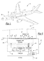
FIG. 1 is an illustration of an aircraft including a center wing tank; -
FIG. 2 is a schematic diagram of the center wing tank shown inFIG. 1 , an air conditioning (AC) pack, and a center wing tank cooling system; -
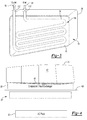
FIG. 3 is a view of a lowermost surface the center wing tank shown inFIG. 2 ; -
FIG. 4 is an alternative embodiment of the center wing tank cooling system shown inFIG. 2 further including a heat shield; and -
FIG. 5 is yet another embodiment of the center wing tank cooling system shown inFIG. 4 , where cooling air may flow between the heat shield and the AC pack. - As shown in
FIG. 1 , the disclosedaircraft 10 may include afuselage 20 andwings 22. Theaircraft 10 may also include acenter wing tank 24 positioned at least partially in thefuselage 20 of theaircraft 10 and adjacent to both thewings 22. Referring to bothFIGS. 1 and 2 , thecenter wing tank 24 may be positioned proximate to one or more air conditioning (AC) packs 30 (shown inFIG. 2 ). Those skilled in the art will readily appreciate that theAC pack 30 is an apparatus responsible for conditioning air drawn from outside theaircraft 10 and supplied to acabin 34. TheAC pack 30 may be part of an environmental control system (ECS) 32 of theaircraft 10. The ECS 32 may be used to control various parameters in thecabin 34 located within thefuselage 20 of theaircraft 10 such as, for example, air temperature, pressure, and humidity. - Turning now to
FIG. 2 , thecenter wing tank 24 may be used to contain or holdfuel 40 that is used for eventual consumption by the aircraft 10 (FIG. 1 ). Thecenter wing tank 24 may also contain a volume of gases above the fuel surface, which is referred to asullage 42. For example, in the embodiment as shown inFIG. 2 , a majority of thefuel 40 contained within thecenter wing tank 24 has been consumed such that thefuel 40 is at aminimum level 48. Accordingly, theullage 42 is at its maximum volume. Thecenter wing tank 24 may be positioned proximate to theAC pack 30 such that theAC pack 30 acts as a heat source that raises the temperature of thefuel 40 contained within thecenter wing tank 24. Heatedfuel 40 may producefuel vapors 44 within thecenter wing tank 24, which are evaporated into theullage 42. In particular, thefuel 40 may settle along alowermost surface 50 of thecenter wing tank 24. Thelowermost surface 50 of thecenter wing tank 24 may be positioned adjacent to one or more of theAC packs 30 such that theAC packs 30 may heat and thereby raise the temperature of thefuel 40 settled along thelowermost surface 50 of thecenter wing tank 24. Although anAC pack 30 is illustrated, it is to be understood that thecenter wing tank 24 may be exposed to other sources of heat within the aircraft 10 (FIG. 1 ) instead such as, for example, heat from the cabin 34 (FIG. 1 ), other fuel tanks located within theaircraft 10, or hydraulic heat exchangers. - In order to reduce the temperature of the
fuel 40 located within thecenter wing tank 24, a center wingtank cooling system 60 may be positioned between thelowermost surface 50 of thecenter wing tank 24 and theAC pack 30. Those skilled in the art will readily appreciate that although acenter wing tank 24 is described, the disclosed cooling system may be applied to other types of fuel tanks located within the aircraft 10 (FIG. 1 ) as well, and that the disclosure should not be limited to only cooling thecenter wing tank 24. - The center wing
tank cooling system 60 may be used to maintain the temperature of thefuel 40 below a predetermined or control temperature, which is explained in greater detail below. The control temperature may be a predetermined amount below a lower flammability limit (LFL) temperature of thefuel 40. The control temperature may act as a margin or buffer to ensure that thefuel 40 is maintained below the LFL temperature. The LFL temperature may be a function of the flash point of thefuel 40 and fuel tank ullage pressure. In an embodiment where thecenter wing tank 24 is an open vented tank, the fuel tank ullage pressure is about atmospheric pressure at altitude. Thus, the control temperature is also based on the flash point of thefuel 40 and fuel tank ullage pressure. For example, if the LFL temperature of one commonly used fuel type is about 38°C (100°F) at a given pressure, then the control temperature may range from about 10°C (80°F) to about 32°C (88°F). However, it is to be understood that these ranges for the predetermined margin are merely exemplary in nature, and may be modified. - The center wing
tank cooling system 60 may include acooling unit 70 and acontrol module 72. In the exemplary embodiment as shown, the coolingunit 70 may include acompressor 80, acondenser 82, anexpansion valve 84, and aheat exchanger 86. Those skilled in the art will appreciate that thecompressor 80, thecondenser 82, theexpansion valve 84, and theheat exchanger 86 create a phasechange cooling system 92. The phasechange cooling system 92 utilizes a cooling fluid, such asrefrigerant 94, that undergoes phase transitions from a liquid to a gas and back again to a liquid in order to provide cooling to thecenter wing tank 24. - It is to be understood that the center wing
tank cooling system 60 should not be limited to only a phase change based cooling system where the refrigerant 94 undergoes phase transitions in order to provide cooling to thecenter wing tank 24. Instead, those skilled in the art will readily appreciate that the phasechange cooling system 92 as illustrated in the figures is merely exemplary in nature and that any other type of cooling system may be used as well such as, for example, an air cycle cooling system or a liquid cooling system. For example, in one approach, bleed air extracted from one or more main engines of theaircraft 10 may be used to provide cooling to thecenter wing tank 24. Moreover, althoughrefrigerant 94 is described, it is to be understood that any other type of cooling fluid may be used as well to draw heat from thecenter wing tank 24 depending on the specific type of cooling system. For example, the cooling fluid may be a liquid if the cooling system is a liquid cooling system, or a gas such as air if the cooling system is an air cycle cooling system. - The exemplary phase
change cooling system 92 operates by compressing the refrigerant 94 in gaseous form by thecompressor 80, dissipating heat from the gas through thecondenser 82 to cause the gas to condense into a fluid, passing the fluid through theexpansion valve 84, and allowing the fluid to flow through theheat exchanger 86. As seen inFIG. 2 , coolingair 96 may flow over thecondenser 82. The coolingair 96 may be used to draw heat from the gas flowing through thecondenser 82. The coolingair 96 may be ram air drawn from outside the aircraft 10 (FIG. 1 ). Alternatively, in another embodiment, the coolingair 96 may be generated by one or more cooling fans (not illustrated in the figures). - The
heat exchanger 86 may be any type of device that allows for cooling fluid to flow through and draw heat from the surrounding environment. For example, in the embodiment as shown inheat exchanger 86 is an evaporator that allows the refrigerant 94 to evaporate from liquid form back to gas form, while drawing heat. In the embodiment as shown inFIG. 2 the refrigerant 94, which is in gas form, is transported back to thecompressor 80. Theheat exchanger 86 may be located along thelowermost surface 50 of thecenter wing tank 24. Theheat exchanger 86 may be used to provide cooling to thefuel 40 located within thecenter wing tank 24. - Turning now to
FIG. 3 , thelowermost surface 50 of thecenter wing tank 24 and theheat exchanger 86 are illustrated. Theheat exchanger 86 may include acooling loop 74, aninlet 110 and anoutlet 112. The refrigerant 94 exiting the expansion valve 84 (FIG. 2 ) enters theheat exchanger 86 through theinlet 110 of thecooling loop 74. As seen inFIG. 3 , the coolingloop 74 is disposed along thelowermost surface 50 of thecenter wing tank 24. The refrigerant 94 flows through thecooling loop 74 in liquid form and draws heat from thelowermost surface 50 of thecenter wing tank 24, thereby providing cooling to thefuel 40 of the center wing tank 24 (FIG. 2 ). In other words, the refrigerant 94 is in thermal communication with thelowermost surface 50 of thecenter wing tank 24 and is used to lower and control the temperature of the fuel 40 (FIG. 2 ) contained within thecenter wing tank 24. As explained above, althoughrefrigerant 94 is discussed, those skilled in the art will readily appreciate that any other type of cooling fluid may be used as well to draw heat from thelowermost surface 50 of thecenter wing tank 24. - Those skilled in the art will also appreciate that while the
cooling loop 74 is disposed along thelowermost surface 50 of thecenter wing tank 24, the coolingloop 74 may be disposed along any other surface of thecenter wing tank 24 as well. However, placing thecooling loop 74 of theheat exchanger 86 along thelowermost surface 50 may provide the most effective cooling available, since the AC packs 30 (FIG. 1 ) radiate heat directly below thecenter wing tank 24. - In the exemplary embodiment as shown in
FIG. 3 , the coolingloop 74 of theheat exchanger 86 is arranged in a serpentine configuration along substantially the entirelowermost surface 50 of thecenter wing tank 24. However, it is to be understood that thecooling loop 74 may be arranged in other configurations along thelowermost surface 50 of thecenter wing tank 24 as well. For example, in another embodiment, the coolingloop 74 may be arranged in a coil configuration along thelowermost surface 50 of thecenter wing tank 24. Moreover, althoughFIG. 3 illustrates thecooling loop 74 covering substantially the entirelowermost surface 50 of thecenter wing tank 24, those skilled in the art will appreciate that thecooling loop 74 may only cover a portion of thelowermost surface 50 of thecenter wing tank 24 as well. Finally, in the embodiment as illustrated in the figures, the coolingloop 74 contacts thelowermost surface 50 of thecenter wing tank 24. However, it is to be understood that in an alternative embodiment, the coolingloop 74 may be embedded or contained within thelowermost surface 50 of thecenter wing tank 24 as well. - Turning back to
FIG. 2 , thecontrol module 72 may be in signal communication with both the phasechange cooling system 92 and atemperature sensor 140. Additionally, thecontrol module 72 may also be in communication with aircraft signals, switches, or sensors that indicate aircraft altitude, pressure, or fuel quantity within thecenter wing tank 24. For example, thecontrol module 72 may monitor aircraft altitude using a dedicated pressure sensor, or by communication with an existing airplane altitude signal. Thetemperature sensor 140 detects the temperature of thefuel 40 within thecenter wing tank 24. Thetemperature sensor 140 may be located along alowermost portion 142 of thecenter wing tank 24. Specifically, it should be appreciated that thetemperature sensor 140 may be positioned along thelowermost portion 142 within thecenter wing tank 24 in order to detect the temperature of thefuel 40 located closest to the AC packs 30. In other words, thetemperature sensor 140 may be positioned within the center wing tank 24 (or another type of fuel tank, if applicable) in order to monitor the hottest portion of thefuel 40 located within thecenter wing tank 24. Those skilled in the art will readily appreciate that thetemperature sensor 140 may be a pre-existing sensor that is already part of thecenter wing tank 24. In other words, the center wingtank cooling system 60 does not require a specialized sensor in order to determine fuel temperature, which in turn reduces the overall cost and complexity of the center wingtank cooling system 60. - The
control module 72 may refer to, or be part of, an application specific integrated circuit (ASIC), an electronic circuit, a combinational logic circuit, a field programmable gate array (FPGA), a processor (shared, dedicated, or group) that executes code, or a combination of some or all of the above, such as in a system-on-chip. Thecontrol module 72 includes control logic for monitoring thetemperature sensor 140. In addition to receiving the temperature of thefuel 40 from thetemperature sensor 140, thecontrol module 72 may also receive as input aircraft altitude. - The
control module 72 also includes control logic for selectively activating the phasechange cooling system 92 based on a fuel temperature and the aircraft altitude. Specifically, thecontrol module 72 monitors thetemperature sensor 140 to determine if the fuel temperature is above or below the control temperature. Thecontrol module 72 also includes control logic for monitoring the aircraft altitude to determine the appropriate control temperature for thefuel 40. As explained above, the LFL temperature of thefuel 40 is based on the fuel tank ullage pressure, and the aircraft altitude is indicative of the fuel tank ullage pressure. In the exemplary embodiment as shown inFIG. 2 , thecontrol module 72 is in signal communication with thecompressor 80, and activates the phasechange cooling system 92 by engaging thecompressor 80 based on the fuel temperature and the aircraft altitude. However, those skilled in the art will readily appreciate that if the cooling system is a liquid cooling system or an air cycle cooling system, then thecontrol module 72 may be in communication with other components of the center wingtank cooling system 60 that control the flow of cooling fluid. - In the event the fuel temperature is above the control temperature, then the
control module 72 includes control logic for sending an activation signal for activating the phasechange cooling system 92. Specifically, in the embodiment as shown inFIG. 2 , thecompressor 80 is engageable by the activation signal. Once thecompressor 80 is engaged, the center wingtank cooling system 60 is operable to provide cooling to thelowermost surface 50 of thecenter wing tank 24. Specifically, if the phasechange cooling system 92 is activated and thecompressor 80 is engaged, the refrigerant 94 may undergo phase transitions in order to provide cooling to thelowermost surface 50 of thecenter wing tank 24. - The
control module 72 continues to keep the phasechange cooling system 92 activated (i.e., thecompressor 80 remains engaged) until thefuel 40 located within thecenter wing tank 24 has been cooled to a lower limit temperature. The lower limit temperature may be a predetermined amount below the control temperature of the fuel. For example, in one embodiment, the lower limit temperature may range from about 0°C below the control temperature to about 5°C below the control temperature, however it is to be understood that these ranges are merely exemplary in nature and may be modified depending on system constraints. In one approach, the lower limit temperature of thefuel 40 may be set or determined such that any liquid water located within thecenter wing tank 24 may not freeze. - The lower limit temperature may be used to ensure that the center wing
tank cooling system 60 does not continue to provide cooling to thecenter wing tank 24 if thelowermost surface 50 has already been cooled sufficiently. Thus, once thetemperature sensor 140 indicates that thefuel 40 is at or below the lower limit temperature, thecontrol module 72 may send a deactivation signal to deactivate the phasechange cooling system 92. Specifically, in the non-limiting embodiment as shown inFIG. 2 , the deactivation signal may be used to disengage thecompressor 80. Once the phasechange cooling system 92 is deactivated, the center wingtank cooling system 60 is no longer operable to provide cooling to thelowermost surface 50 of thecenter wing tank 24. - In one exemplary embodiment, the
control module 72 may further include forward thinking logic that determines a specific turn-on time as well as a turn-off time of the center wingtank cooling system 60. Specifically, thecontrol module 72 may monitor the heating rate or thermal inertia of thefuel 40 by continuously monitoring thetemperature sensor 140 over a specified period of time. Thecontrol module 72 may also monitor a fuel level of thefuel 40 within thecenter wing tank 24 as well by monitoring a liquid level sensor (not illustrated). Thecontrol module 72 may then determine the specific turn-on time of the center wingtank cooling system 60 based on the thermal inertia as well as the fuel level of thefuel 40. Additionally, thecontrol module 72 may also determine the specific turn-off time of the center wingtank cooling system 60 based on the thermal inertia as well as the fuel level of thefuel 40. Those skilled in the art will readily appreciate that the forward thinking logic of thecontrol module 72 may set the turn-on and the turn-off times of thecompressor 80 based on real time trends in the fuel level as well as the heating or cooling rate of thefuel 40, and may ultimately provide a more efficient approach for maintaining the temperature of thefuel 40 below the control temperature. -
FIG. 4 is an alternative embodiment of the center wingtank cooling system 60. In particular, aheat shield 150 may be placed directly below theheat exchanger 86. Theheat shield 150 may be used to deflect heat radiated by heat generating components of the center wingtank cooling system 60 such as, for example, the compressor 80 (shown inFIG. 2 ). Thus, theheat shield 150 may reduce temperature of thefuel 40 located within thecenter wing tank 24. As a result, the center wingtank cooling system 60 may be activated less often or for a shorter period of time. Moreover, the center wingtank cooling system 60 may also be smaller and more compact when compared to a cooling system where theheat shield 150 is not included. -
FIG. 5 is yet another embodiment of the center wingtank cooling system 60 including theheat shield 150. In the embodiment as shown inFIG. 5 , coolingair 160 may be introduced around the heat generating components of the center wing tank cooling system 60 (i.e., thecompressor 80 shown inFIG. 2 ) as well as theAC pack 30. The coolingair 160 may be used to dissipate heat radiated by the heat generating components of the center wingtank cooling system 60 as well as theAC pack 30. The coolingair 160 may either be ram air drawn from outside the aircraft 10 (FIG. 1 ), or air generated by a cooling fan (not illustrated in the figures). In the event the coolingair 160 is ram air, it is to be understood that theheat shield 150 may be omitted. The coolingair 160 may further reduce temperature of thefuel 40 located within thecenter wing tank 24. Thus, the center wingtank cooling system 60 may be activated less often or for a short period of time. Moreover, the center wingtank cooling system 60 may also be smaller and more compact when compared to a cooling system where the coolingair 160 is not used. - Referring generally to the figures, the disclosed center wing tank cooling system may provide a relatively simple approach for maintaining the temperature of fuel located within the center wing tank of the aircraft. Those skilled in the art will readily understand the importance of maintaining the temperature of the fuel within the center wing tank substantially below the LFL temperature. The disclosed center wing tank cooling system provides an automated, cost-effective approach for maintaining the temperature of the fuel within the center wing tank at or below the control temperature to ensure the fuel temperature is within a specific range.
- Further, the disclosure comprises embodiments according to the following clauses:
- Clause 1. A cooling system for a fuel tank of an aircraft, comprising:
- a temperature sensor for detecting a fuel temperature within the fuel tank, wherein the cooling system maintains the fuel temperature below a control temperature;
- a cooling system including a heat exchanger, wherein a cooling fluid flows through the heat exchanger and is in thermal communication with a surface of the fuel tank; and
- a control module in signal communication with the temperature sensor and the cooling system, the control module including control logic for:
- monitoring the temperature sensor;
- determining if the fuel temperature is above the control temperature; and
- generating an activation signal to activate the cooling system if the fuel temperature is above the control temperature.
- Clause 2. The cooling system as recited in clause 1, wherein the control temperature is based on a flash point of a fuel and a ullage pressure of the fuel tank.
- Clause 3. The cooling system as recited in clause 1, wherein the heat exchanger comprises a cooling loop, and wherein the cooling fluid flows through the cooling loop.
- Clause 4. The cooling system as recited in clause 3, wherein the cooling loop contacts a lowermost surface of the fuel tank.
- Clause 5. The cooling system as recited in clause 3, wherein the cooling loop is embedded within a lowermost surface of the fuel tank.
- Clause 6. The cooling system as recited in clause 3, wherein the cooling loop is arranged in a serpentine configuration along a lowermost surface of the fuel tank.
- Clause 7. The cooling system as recited in clause 1, wherein the control temperature is a predetermined margin below a lower flammability limit (LFL) temperature of a fuel.
- Clause 8. The cooling system as recited in clause 1, wherein the control temperature ranges from about 10°C to about 32°C.
- Clause 9. The cooling system as recited in clause 1, further comprising a heat shield located directly below the heat exchanger.
-
Clause 10. The cooling system as recited in clause 9, wherein cooling air is introduced around an AC pack and heat generating components of the cooling system. - Clause 11. The cooling system as recited in clause 1, wherein the cooling system comprises a condenser, an expansion valve, and a refrigerant.
- Clause 12. The cooling system as recited in clause 11, wherein the cooling fluid is the refrigerant, and wherein the refrigerant flows through the heat exchanger to provide cooling to the fuel tank.
- Clause 13. The cooling system as recited in clause 1, wherein the control module includes control logic for generating a deactivation signal to deactivate the cooling system, wherein the control module generates the deactivation signal if the temperature sensor indicates the fuel temperature is at a lower limit temperature.
- Clause 14. The cooling system as recited in clause 13, wherein the lower limit temperature ranges from about 0°C below the control temperature to about 5°C below the control temperature.
- Clause 15. A method of cooling a center wing tank of an aircraft, comprising:
- detecting a fuel temperature within the center wing tank by a temperature sensor;
- monitoring the temperature sensor by a control module, wherein the control module is in signal communication with the temperature sensor;
- determining if the fuel temperature is above a control temperature by the control module;
- generating an activation signal, by the control module, if the fuel temperature is above the control temperature, wherein the control module is in signal communication with a cooling system;
- activating the cooling system if the activation signal is generated; and
- flowing cooling fluid through a heat exchanger if the cooling system is activated, wherein the cooling fluid is in thermal communication with a surface of the center wing tank.
- Clause 16. The method of clause 15, comprising providing a heat shield located directly below the heat exchanger.
- Clause 17. The method of clause 16, comprising providing cooling air around an AC pack and heat generating components of the cooling system.
- Clause 18. The method of clause 15, comprising generating a deactivation signal by the control module if the temperature sensor indicates the fuel temperature is at a lower limit temperature, wherein the activation signal deactivates the cooling system.
- Clause 19. The method of clause 15, comprising a cooling loop that is part of the heat exchanger, and wherein the cooling fluid flows through the cooling loop.
-
Clause 20. The method of clause 19, wherein the cooling loop either contacts a lowermost surface of the center wing tank or is embedded within a lowermost surface of the center wing tank. - While the forms of apparatus and methods herein described constitute preferred aspects of this disclosure, it is to be understood that the disclosure is not limited to these precise forms of apparatus and methods, and the changes may be made therein without departing from the scope of the disclosure.
Claims (15)
- A cooling system (60) for a fuel tank of an aircraft, comprising:a temperature sensor (140) for detecting a fuel temperature within the fuel tank (24), wherein the cooling system maintains the fuel temperature below a control temperature;a cooling system including a heat exchanger (86), wherein a cooling fluid flows through the heat exchanger (86) and is in thermal communication with a surface of the fuel tank (24); anda control module (72) in signal communication with the temperature sensor (140) and the cooling system, the control module including control logic for:monitoring the temperature sensor (140);determining if the fuel (40) temperature is above the control temperature; andgenerating an activation signal to activate the cooling system (60) if the fuel temperature is above the control temperature.
- The cooling system (60) of claim 1, wherein the control temperature is based on a flash point of a fuel and a ullage pressure of the fuel tank.
- The cooling system (60) of claim 1 or claim 2, wherein the heat exchanger (86) comprises a cooling loop (74), and wherein the cooling fluid flows through the cooling loop (74).
- The cooling system (60) of claim 3, wherein the cooling loop (74) contacts a lowermost surface (50) of the fuel tank.
- The cooling system (60) of claim 3, wherein the cooling loop (74) is embedded within a lowermost surface (50) of the fuel tank.
- The cooling system (60) of claim 3, wherein the cooling loop (74) is arranged in a serpentine configuration along a lowermost surface (50) of the fuel tank.
- The cooling system (60) of any preceding claim, wherein the control temperature is a predetermined margin below a lower flammability limit (LFL) temperature of a fuel.
- The cooling system (60) of any preceding claim, wherein the control temperature ranges from about 10°C to about 32°C.
- The cooling system (60) of any preceding claim, further comprising a heat shield (150) located directly below the heat exchanger (86).
- The cooling system (60) of claim 9, wherein cooling air (160) is introduced around an AC pack (30) and heat generating components of the cooling system.
- The cooling system (60) of any preceding claim, wherein the cooling system (60) comprises a condenser (82), an expansion valve (84), and a refrigerant (94).
- The cooling system (60) as recited in claim 11, wherein the cooling fluid is the refrigerant (94), and wherein the refrigerant flows through the heat exchanger to provide cooling to the fuel tank.
- The cooling system (60) of any preceding claim, wherein the control module (72) includes control logic for generating a deactivation signal to deactivate the cooling system (60), wherein the control module generates the deactivation signal if the temperature sensor (140) indicates the fuel temperature is at a lower limit temperature.
- The cooling system (60) of claim 13, wherein the lower limit temperature ranges from about 0°C below the control temperature to about 5°C below the control temperature.
- A method of cooling a center wing tank of an aircraft, comprising:detecting a fuel temperature within the center wing tank (24) by a temperature sensor (140);monitoring the temperature sensor (140) by a control module (72), wherein the control module (72) is in signal communication with the temperature sensor (140);determining if the fuel temperature is above a control temperature by the control module (72);generating an activation signal, by the control module (72), if the fuel temperature is above the control temperature, wherein the control module (72) is in signal communication with a cooling system (60);activating the cooling system (60) if the activation signal is generated; andflowing cooling fluid (94) through a heat exchanger (86) if the cooling system (60) is activated, wherein the cooling fluid is in thermal communication with a surface of the center wing tank (24).
Applications Claiming Priority (1)
| Application Number | Priority Date | Filing Date | Title |
|---|---|---|---|
| US14/557,959 US9718556B2 (en) | 2014-12-02 | 2014-12-02 | Cooling system for a center wing tank of an aircraft |
Publications (2)
| Publication Number | Publication Date |
|---|---|
| EP3028944A1 true EP3028944A1 (en) | 2016-06-08 |
| EP3028944B1 EP3028944B1 (en) | 2020-02-26 |
Family
ID=54770984
Family Applications (1)
| Application Number | Title | Priority Date | Filing Date |
|---|---|---|---|
| EP15197436.7A Active EP3028944B1 (en) | 2014-12-02 | 2015-12-02 | Fuel tank of an aircraft and cooling system |
Country Status (7)
| Country | Link |
|---|---|
| US (1) | US9718556B2 (en) |
| EP (1) | EP3028944B1 (en) |
| JP (1) | JP6917124B2 (en) |
| CN (1) | CN105644794B (en) |
| BR (1) | BR102015028698B1 (en) |
| CA (1) | CA2909723C (en) |
| RU (1) | RU2703662C2 (en) |
Families Citing this family (12)
| Publication number | Priority date | Publication date | Assignee | Title |
|---|---|---|---|---|
| GB2557302A (en) * | 2016-12-05 | 2018-06-20 | Airbus Operations Ltd | An aircraft fuel tank |
| CN106672249A (en) * | 2016-12-15 | 2017-05-17 | 中国航空工业集团公司西安飞机设计研究所 | High-temperature gas cooling device of aircraft fuel inerting system |
| CN108100273B (en) * | 2017-11-29 | 2021-08-17 | 中国航空工业集团公司沈阳飞机设计研究所 | Aircraft fuel cooling system |
| CN108910061B (en) * | 2018-08-07 | 2020-04-03 | 晨龙飞机(荆门)有限公司 | Pressure type passenger plane oil tank device |
| CN109018385A (en) * | 2018-08-16 | 2018-12-18 | 晨龙飞机(荆门)有限公司 | A kind of fuel tanker automatically adjusting spin manifold temperature |
| US11155359B2 (en) * | 2019-09-19 | 2021-10-26 | Embraer S.A. | Aircraft fuel tank pressurization systems and methods |
| US11713132B2 (en) | 2019-10-04 | 2023-08-01 | Hamilton Sundstrand Corporation | Fuel tank inerting system and method |
| CN111086645B (en) * | 2020-01-06 | 2021-04-06 | 南京航空航天大学 | Device for reducing combustibility of oil tank by using ring control cold system and working method |
| CN111717404B (en) * | 2020-05-20 | 2022-05-20 | 北京空天技术研究所 | Oil tank thermal protection structure for high-speed aircraft and high-speed aircraft with oil tank thermal protection structure |
| DE102020216090A1 (en) * | 2020-12-16 | 2022-06-23 | MTU Aero Engines AG | Cooling system for an aircraft, aircraft with a cooling system and method for cooling an electrical drive system of an aircraft |
| US20240158094A1 (en) * | 2022-11-10 | 2024-05-16 | Rapidflight Holdings Llc | Additive manufactured fuel tanks |
| US20250314194A1 (en) * | 2024-04-09 | 2025-10-09 | Pratt & Whitney Canada Corp. | Heat exchanger cooling assembly for an aircraft propulsion system |
Citations (6)
| Publication number | Priority date | Publication date | Assignee | Title |
|---|---|---|---|---|
| US4505124A (en) * | 1983-09-22 | 1985-03-19 | The United States Of America As Represented By The Secretary Of The Air Force | Heat management system for aircraft |
| US20050224654A1 (en) * | 2004-02-10 | 2005-10-13 | Loss Kevin L | Methods and systems for controlling flammability control systems in aircraft and other vehicles |
| US20100108811A1 (en) * | 2008-10-30 | 2010-05-06 | Alankar Gupta | System and method to make a fuel tank inert |
| EP2592000A1 (en) * | 2011-11-08 | 2013-05-15 | Alenia Aermacchi S.p.A. | Fuel tank for aircraft provided with a fuel heating system, and fuel heating system for aircraft fitted with such a tank |
| EP2594487A2 (en) * | 2011-11-17 | 2013-05-22 | The Boeing Company | Fuel tank flammability reduction and inerting system and methods thereof |
| US20140208943A1 (en) * | 2012-03-27 | 2014-07-31 | The Boeing Company | Method and system for reducing the flammability of fuel-tanks onboard an aircraft |
Family Cites Families (8)
| Publication number | Priority date | Publication date | Assignee | Title |
|---|---|---|---|---|
| US3556199A (en) * | 1968-05-13 | 1971-01-19 | United Aircraft Prod | Free convection cooling method and apparatus |
| US5738304A (en) * | 1997-01-10 | 1998-04-14 | Tavano; John B. | Emergency aircraft fuel system |
| US7152635B2 (en) * | 2004-02-10 | 2006-12-26 | The Boeing Company | Commercial aircraft on-board inerting system |
| DE102007060428B3 (en) * | 2007-12-14 | 2009-05-07 | Airbus Deutschland Gmbh | Fuel cell system i.e. evaporation-cooled fuel cell system, for use in aircraft, has control unit controlling temperature of cell, where cooling agent is transferred into gaseous state in aggregate condition |
| RU120150U1 (en) * | 2011-05-24 | 2012-09-10 | Федеральное государственное военное образовательное учреждение высшего профессионального образования "Военный учебно-научный центр Сухопутных войск Общевойсковая академия Вооруженных Сил Российской Федерации" | THERMAL COMPENSATING FUEL SYSTEM |
| GB201204959D0 (en) * | 2012-03-21 | 2012-05-02 | Airbus Operations Ltd | Conditioning system for fuel cell exhaust |
| US20150151845A1 (en) * | 2013-12-02 | 2015-06-04 | Aero Systems Consultants LLC | Aircraft fuel systems |
| US9656756B2 (en) * | 2014-03-10 | 2017-05-23 | The Boeing Company | Turbo-compressor system and method for extracting energy from an aircraft engine |
-
2014
- 2014-12-02 US US14/557,959 patent/US9718556B2/en active Active
-
2015
- 2015-10-01 RU RU2015141770A patent/RU2703662C2/en active
- 2015-10-07 JP JP2015199215A patent/JP6917124B2/en active Active
- 2015-10-20 CA CA2909723A patent/CA2909723C/en active Active
- 2015-11-10 CN CN201510761494.XA patent/CN105644794B/en active Active
- 2015-11-16 BR BR102015028698-8A patent/BR102015028698B1/en active IP Right Grant
- 2015-12-02 EP EP15197436.7A patent/EP3028944B1/en active Active
Patent Citations (6)
| Publication number | Priority date | Publication date | Assignee | Title |
|---|---|---|---|---|
| US4505124A (en) * | 1983-09-22 | 1985-03-19 | The United States Of America As Represented By The Secretary Of The Air Force | Heat management system for aircraft |
| US20050224654A1 (en) * | 2004-02-10 | 2005-10-13 | Loss Kevin L | Methods and systems for controlling flammability control systems in aircraft and other vehicles |
| US20100108811A1 (en) * | 2008-10-30 | 2010-05-06 | Alankar Gupta | System and method to make a fuel tank inert |
| EP2592000A1 (en) * | 2011-11-08 | 2013-05-15 | Alenia Aermacchi S.p.A. | Fuel tank for aircraft provided with a fuel heating system, and fuel heating system for aircraft fitted with such a tank |
| EP2594487A2 (en) * | 2011-11-17 | 2013-05-22 | The Boeing Company | Fuel tank flammability reduction and inerting system and methods thereof |
| US20140208943A1 (en) * | 2012-03-27 | 2014-07-31 | The Boeing Company | Method and system for reducing the flammability of fuel-tanks onboard an aircraft |
Also Published As
| Publication number | Publication date |
|---|---|
| JP6917124B2 (en) | 2021-08-11 |
| CN105644794B (en) | 2020-04-10 |
| RU2703662C2 (en) | 2019-10-21 |
| BR102015028698B1 (en) | 2022-07-12 |
| EP3028944B1 (en) | 2020-02-26 |
| CN105644794A (en) | 2016-06-08 |
| RU2015141770A3 (en) | 2019-04-09 |
| JP2016107973A (en) | 2016-06-20 |
| RU2015141770A (en) | 2017-04-06 |
| US9718556B2 (en) | 2017-08-01 |
| CA2909723A1 (en) | 2016-06-02 |
| BR102015028698A2 (en) | 2016-08-02 |
| US20160152343A1 (en) | 2016-06-02 |
| CA2909723C (en) | 2020-01-14 |
Similar Documents
| Publication | Publication Date | Title |
|---|---|---|
| US9718556B2 (en) | Cooling system for a center wing tank of an aircraft | |
| EP2644508B1 (en) | System and method for cooling electrical components | |
| CN103765128B (en) | Vehicle refrigerator with liquid-line subcooled evaporative loop system | |
| US20150068703A1 (en) | Thermal management system and method of assembling the same | |
| EP2815978B1 (en) | Aircraft refrigeration unit evaporator heater | |
| CN109196966A (en) | The reduction of heat system of automatic driving vehicle | |
| GB2512442A8 (en) | Regulated oil cooling system for a turbine engine with deicing of the nacelle | |
| EP3123085A1 (en) | Vehicle refrigeration equipment having a liquid heat rejection system | |
| BR102014021726B1 (en) | SYSTEM FOR REFRIGERATION OF GALLEY COMPARTMENTS AND METHOD OF OPERATION OF A REFRIGERATION SYSTEM | |
| EP2805883B1 (en) | Aircraft cooling system | |
| EP3670352B1 (en) | Aircraft systems and methods utilizing waste heat in fuel | |
| RU2531210C1 (en) | Method of providing thermal regime of instrument compartment of aircraft | |
| US9726404B2 (en) | Cooling system with a plurality of subcoolers | |
| US20190056161A1 (en) | Thermostatic expansion valves and methods of control | |
| CN109708373A (en) | Refrigerated compartment peculiar to vessel with semiconductor cooling device | |
| US20240167733A1 (en) | A cold storage, a method of operating a cold storage, and a cooling system | |
| CN106364663B (en) | Aircraft air conditioning module cabin | |
| EP2801526A1 (en) | Galley cooling heat exchanger defrost mechanism | |
| US9322584B2 (en) | Cooling system for operation with a two-phase refrigerant |
Legal Events
| Date | Code | Title | Description |
|---|---|---|---|
| PUAI | Public reference made under article 153(3) epc to a published international application that has entered the european phase |
Free format text: ORIGINAL CODE: 0009012 |
|
| AK | Designated contracting states |
Kind code of ref document: A1 Designated state(s): AL AT BE BG CH CY CZ DE DK EE ES FI FR GB GR HR HU IE IS IT LI LT LU LV MC MK MT NL NO PL PT RO RS SE SI SK SM TR |
|
| AX | Request for extension of the european patent |
Extension state: BA ME |
|
| STAA | Information on the status of an ep patent application or granted ep patent |
Free format text: STATUS: REQUEST FOR EXAMINATION WAS MADE |
|
| 17P | Request for examination filed |
Effective date: 20161206 |
|
| RBV | Designated contracting states (corrected) |
Designated state(s): AL AT BE BG CH CY CZ DE DK EE ES FI FR GB GR HR HU IE IS IT LI LT LU LV MC MK MT NL NO PL PT RO RS SE SI SK SM TR |
|
| REG | Reference to a national code |
Ref country code: DE Ref legal event code: R079 Ref document number: 602015047632 Country of ref document: DE Free format text: PREVIOUS MAIN CLASS: B64D0037320000 Ipc: B64D0037040000 |
|
| GRAP | Despatch of communication of intention to grant a patent |
Free format text: ORIGINAL CODE: EPIDOSNIGR1 |
|
| STAA | Information on the status of an ep patent application or granted ep patent |
Free format text: STATUS: GRANT OF PATENT IS INTENDED |
|
| RIC1 | Information provided on ipc code assigned before grant |
Ipc: B64D 37/34 20060101ALI20190408BHEP Ipc: B64D 37/32 20060101ALI20190408BHEP Ipc: B64D 37/04 20060101AFI20190408BHEP |
|
| INTG | Intention to grant announced |
Effective date: 20190515 |
|
| GRAJ | Information related to disapproval of communication of intention to grant by the applicant or resumption of examination proceedings by the epo deleted |
Free format text: ORIGINAL CODE: EPIDOSDIGR1 |
|
| STAA | Information on the status of an ep patent application or granted ep patent |
Free format text: STATUS: REQUEST FOR EXAMINATION WAS MADE |
|
| GRAP | Despatch of communication of intention to grant a patent |
Free format text: ORIGINAL CODE: EPIDOSNIGR1 |
|
| STAA | Information on the status of an ep patent application or granted ep patent |
Free format text: STATUS: GRANT OF PATENT IS INTENDED |
|
| INTC | Intention to grant announced (deleted) | ||
| INTG | Intention to grant announced |
Effective date: 20190919 |
|
| GRAS | Grant fee paid |
Free format text: ORIGINAL CODE: EPIDOSNIGR3 |
|
| GRAA | (expected) grant |
Free format text: ORIGINAL CODE: 0009210 |
|
| STAA | Information on the status of an ep patent application or granted ep patent |
Free format text: STATUS: THE PATENT HAS BEEN GRANTED |
|
| AK | Designated contracting states |
Kind code of ref document: B1 Designated state(s): AL AT BE BG CH CY CZ DE DK EE ES FI FR GB GR HR HU IE IS IT LI LT LU LV MC MK MT NL NO PL PT RO RS SE SI SK SM TR |
|
| REG | Reference to a national code |
Ref country code: GB Ref legal event code: FG4D |
|
| REG | Reference to a national code |
Ref country code: CH Ref legal event code: EP |
|
| REG | Reference to a national code |
Ref country code: DE Ref legal event code: R096 Ref document number: 602015047632 Country of ref document: DE |
|
| REG | Reference to a national code |
Ref country code: AT Ref legal event code: REF Ref document number: 1237344 Country of ref document: AT Kind code of ref document: T Effective date: 20200315 |
|
| REG | Reference to a national code |
Ref country code: IE Ref legal event code: FG4D |
|
| PG25 | Lapsed in a contracting state [announced via postgrant information from national office to epo] |
Ref country code: FI Free format text: LAPSE BECAUSE OF FAILURE TO SUBMIT A TRANSLATION OF THE DESCRIPTION OR TO PAY THE FEE WITHIN THE PRESCRIBED TIME-LIMIT Effective date: 20200226 Ref country code: NO Free format text: LAPSE BECAUSE OF FAILURE TO SUBMIT A TRANSLATION OF THE DESCRIPTION OR TO PAY THE FEE WITHIN THE PRESCRIBED TIME-LIMIT Effective date: 20200526 Ref country code: RS Free format text: LAPSE BECAUSE OF FAILURE TO SUBMIT A TRANSLATION OF THE DESCRIPTION OR TO PAY THE FEE WITHIN THE PRESCRIBED TIME-LIMIT Effective date: 20200226 |
|
| REG | Reference to a national code |
Ref country code: NL Ref legal event code: MP Effective date: 20200226 |
|
| REG | Reference to a national code |
Ref country code: LT Ref legal event code: MG4D |
|
| PG25 | Lapsed in a contracting state [announced via postgrant information from national office to epo] |
Ref country code: GR Free format text: LAPSE BECAUSE OF FAILURE TO SUBMIT A TRANSLATION OF THE DESCRIPTION OR TO PAY THE FEE WITHIN THE PRESCRIBED TIME-LIMIT Effective date: 20200527 Ref country code: IS Free format text: LAPSE BECAUSE OF FAILURE TO SUBMIT A TRANSLATION OF THE DESCRIPTION OR TO PAY THE FEE WITHIN THE PRESCRIBED TIME-LIMIT Effective date: 20200626 Ref country code: BG Free format text: LAPSE BECAUSE OF FAILURE TO SUBMIT A TRANSLATION OF THE DESCRIPTION OR TO PAY THE FEE WITHIN THE PRESCRIBED TIME-LIMIT Effective date: 20200526 Ref country code: HR Free format text: LAPSE BECAUSE OF FAILURE TO SUBMIT A TRANSLATION OF THE DESCRIPTION OR TO PAY THE FEE WITHIN THE PRESCRIBED TIME-LIMIT Effective date: 20200226 Ref country code: LV Free format text: LAPSE BECAUSE OF FAILURE TO SUBMIT A TRANSLATION OF THE DESCRIPTION OR TO PAY THE FEE WITHIN THE PRESCRIBED TIME-LIMIT Effective date: 20200226 Ref country code: SE Free format text: LAPSE BECAUSE OF FAILURE TO SUBMIT A TRANSLATION OF THE DESCRIPTION OR TO PAY THE FEE WITHIN THE PRESCRIBED TIME-LIMIT Effective date: 20200226 |
|
| PG25 | Lapsed in a contracting state [announced via postgrant information from national office to epo] |
Ref country code: NL Free format text: LAPSE BECAUSE OF FAILURE TO SUBMIT A TRANSLATION OF THE DESCRIPTION OR TO PAY THE FEE WITHIN THE PRESCRIBED TIME-LIMIT Effective date: 20200226 |
|
| PG25 | Lapsed in a contracting state [announced via postgrant information from national office to epo] |
Ref country code: CZ Free format text: LAPSE BECAUSE OF FAILURE TO SUBMIT A TRANSLATION OF THE DESCRIPTION OR TO PAY THE FEE WITHIN THE PRESCRIBED TIME-LIMIT Effective date: 20200226 Ref country code: SM Free format text: LAPSE BECAUSE OF FAILURE TO SUBMIT A TRANSLATION OF THE DESCRIPTION OR TO PAY THE FEE WITHIN THE PRESCRIBED TIME-LIMIT Effective date: 20200226 Ref country code: LT Free format text: LAPSE BECAUSE OF FAILURE TO SUBMIT A TRANSLATION OF THE DESCRIPTION OR TO PAY THE FEE WITHIN THE PRESCRIBED TIME-LIMIT Effective date: 20200226 Ref country code: EE Free format text: LAPSE BECAUSE OF FAILURE TO SUBMIT A TRANSLATION OF THE DESCRIPTION OR TO PAY THE FEE WITHIN THE PRESCRIBED TIME-LIMIT Effective date: 20200226 Ref country code: ES Free format text: LAPSE BECAUSE OF FAILURE TO SUBMIT A TRANSLATION OF THE DESCRIPTION OR TO PAY THE FEE WITHIN THE PRESCRIBED TIME-LIMIT Effective date: 20200226 Ref country code: PT Free format text: LAPSE BECAUSE OF FAILURE TO SUBMIT A TRANSLATION OF THE DESCRIPTION OR TO PAY THE FEE WITHIN THE PRESCRIBED TIME-LIMIT Effective date: 20200719 Ref country code: DK Free format text: LAPSE BECAUSE OF FAILURE TO SUBMIT A TRANSLATION OF THE DESCRIPTION OR TO PAY THE FEE WITHIN THE PRESCRIBED TIME-LIMIT Effective date: 20200226 Ref country code: RO Free format text: LAPSE BECAUSE OF FAILURE TO SUBMIT A TRANSLATION OF THE DESCRIPTION OR TO PAY THE FEE WITHIN THE PRESCRIBED TIME-LIMIT Effective date: 20200226 Ref country code: SK Free format text: LAPSE BECAUSE OF FAILURE TO SUBMIT A TRANSLATION OF THE DESCRIPTION OR TO PAY THE FEE WITHIN THE PRESCRIBED TIME-LIMIT Effective date: 20200226 |
|
| REG | Reference to a national code |
Ref country code: AT Ref legal event code: MK05 Ref document number: 1237344 Country of ref document: AT Kind code of ref document: T Effective date: 20200226 |
|
| REG | Reference to a national code |
Ref country code: DE Ref legal event code: R097 Ref document number: 602015047632 Country of ref document: DE |
|
| PLBE | No opposition filed within time limit |
Free format text: ORIGINAL CODE: 0009261 |
|
| STAA | Information on the status of an ep patent application or granted ep patent |
Free format text: STATUS: NO OPPOSITION FILED WITHIN TIME LIMIT |
|
| PG25 | Lapsed in a contracting state [announced via postgrant information from national office to epo] |
Ref country code: IT Free format text: LAPSE BECAUSE OF FAILURE TO SUBMIT A TRANSLATION OF THE DESCRIPTION OR TO PAY THE FEE WITHIN THE PRESCRIBED TIME-LIMIT Effective date: 20200226 Ref country code: AT Free format text: LAPSE BECAUSE OF FAILURE TO SUBMIT A TRANSLATION OF THE DESCRIPTION OR TO PAY THE FEE WITHIN THE PRESCRIBED TIME-LIMIT Effective date: 20200226 |
|
| 26N | No opposition filed |
Effective date: 20201127 |
|
| PG25 | Lapsed in a contracting state [announced via postgrant information from national office to epo] |
Ref country code: PL Free format text: LAPSE BECAUSE OF FAILURE TO SUBMIT A TRANSLATION OF THE DESCRIPTION OR TO PAY THE FEE WITHIN THE PRESCRIBED TIME-LIMIT Effective date: 20200226 Ref country code: SI Free format text: LAPSE BECAUSE OF FAILURE TO SUBMIT A TRANSLATION OF THE DESCRIPTION OR TO PAY THE FEE WITHIN THE PRESCRIBED TIME-LIMIT Effective date: 20200226 |
|
| REG | Reference to a national code |
Ref country code: CH Ref legal event code: PL |
|
| PG25 | Lapsed in a contracting state [announced via postgrant information from national office to epo] |
Ref country code: MC Free format text: LAPSE BECAUSE OF FAILURE TO SUBMIT A TRANSLATION OF THE DESCRIPTION OR TO PAY THE FEE WITHIN THE PRESCRIBED TIME-LIMIT Effective date: 20200226 |
|
| REG | Reference to a national code |
Ref country code: BE Ref legal event code: MM Effective date: 20201231 |
|
| PG25 | Lapsed in a contracting state [announced via postgrant information from national office to epo] |
Ref country code: LU Free format text: LAPSE BECAUSE OF NON-PAYMENT OF DUE FEES Effective date: 20201202 Ref country code: IE Free format text: LAPSE BECAUSE OF NON-PAYMENT OF DUE FEES Effective date: 20201202 |
|
| PG25 | Lapsed in a contracting state [announced via postgrant information from national office to epo] |
Ref country code: LI Free format text: LAPSE BECAUSE OF NON-PAYMENT OF DUE FEES Effective date: 20201231 Ref country code: CH Free format text: LAPSE BECAUSE OF NON-PAYMENT OF DUE FEES Effective date: 20201231 |
|
| PG25 | Lapsed in a contracting state [announced via postgrant information from national office to epo] |
Ref country code: TR Free format text: LAPSE BECAUSE OF FAILURE TO SUBMIT A TRANSLATION OF THE DESCRIPTION OR TO PAY THE FEE WITHIN THE PRESCRIBED TIME-LIMIT Effective date: 20200226 Ref country code: MT Free format text: LAPSE BECAUSE OF FAILURE TO SUBMIT A TRANSLATION OF THE DESCRIPTION OR TO PAY THE FEE WITHIN THE PRESCRIBED TIME-LIMIT Effective date: 20200226 Ref country code: CY Free format text: LAPSE BECAUSE OF FAILURE TO SUBMIT A TRANSLATION OF THE DESCRIPTION OR TO PAY THE FEE WITHIN THE PRESCRIBED TIME-LIMIT Effective date: 20200226 |
|
| PG25 | Lapsed in a contracting state [announced via postgrant information from national office to epo] |
Ref country code: MK Free format text: LAPSE BECAUSE OF FAILURE TO SUBMIT A TRANSLATION OF THE DESCRIPTION OR TO PAY THE FEE WITHIN THE PRESCRIBED TIME-LIMIT Effective date: 20200226 Ref country code: AL Free format text: LAPSE BECAUSE OF FAILURE TO SUBMIT A TRANSLATION OF THE DESCRIPTION OR TO PAY THE FEE WITHIN THE PRESCRIBED TIME-LIMIT Effective date: 20200226 |
|
| PG25 | Lapsed in a contracting state [announced via postgrant information from national office to epo] |
Ref country code: BE Free format text: LAPSE BECAUSE OF NON-PAYMENT OF DUE FEES Effective date: 20201231 |
|
| P01 | Opt-out of the competence of the unified patent court (upc) registered |
Effective date: 20230516 |
|
| PGFP | Annual fee paid to national office [announced via postgrant information from national office to epo] |
Ref country code: GB Payment date: 20251229 Year of fee payment: 11 |
|
| PGFP | Annual fee paid to national office [announced via postgrant information from national office to epo] |
Ref country code: FR Payment date: 20251226 Year of fee payment: 11 |
|
| PGFP | Annual fee paid to national office [announced via postgrant information from national office to epo] |
Ref country code: DE Payment date: 20251229 Year of fee payment: 11 |