EP3028740A1 - Antenne pour un dispositif médical implantable - Google Patents
Antenne pour un dispositif médical implantable Download PDFInfo
- Publication number
- EP3028740A1 EP3028740A1 EP15193419.7A EP15193419A EP3028740A1 EP 3028740 A1 EP3028740 A1 EP 3028740A1 EP 15193419 A EP15193419 A EP 15193419A EP 3028740 A1 EP3028740 A1 EP 3028740A1
- Authority
- EP
- European Patent Office
- Prior art keywords
- antenna
- conducting
- conducting member
- section
- antenna according
- Prior art date
- Legal status (The legal status is an assumption and is not a legal conclusion. Google has not performed a legal analysis and makes no representation as to the accuracy of the status listed.)
- Granted
Links
- 239000002184 metal Substances 0.000 description 9
- 229910052751 metal Inorganic materials 0.000 description 9
- 238000013461 design Methods 0.000 description 6
- 239000000463 material Substances 0.000 description 5
- 239000007943 implant Substances 0.000 description 4
- RTAQQCXQSZGOHL-UHFFFAOYSA-N Titanium Chemical compound [Ti] RTAQQCXQSZGOHL-UHFFFAOYSA-N 0.000 description 3
- 238000004891 communication Methods 0.000 description 3
- 230000005404 monopole Effects 0.000 description 3
- 239000007787 solid Substances 0.000 description 3
- 210000001519 tissue Anatomy 0.000 description 3
- 239000010936 titanium Substances 0.000 description 3
- 229910052719 titanium Inorganic materials 0.000 description 3
- 239000011358 absorbing material Substances 0.000 description 2
- WYTGDNHDOZPMIW-RCBQFDQVSA-N alstonine Natural products C1=CC2=C3C=CC=CC3=NC2=C2N1C[C@H]1[C@H](C)OC=C(C(=O)OC)[C@H]1C2 WYTGDNHDOZPMIW-RCBQFDQVSA-N 0.000 description 2
- 239000004020 conductor Substances 0.000 description 2
- 238000003384 imaging method Methods 0.000 description 2
- 238000004519 manufacturing process Methods 0.000 description 2
- 238000000034 method Methods 0.000 description 2
- 238000012544 monitoring process Methods 0.000 description 2
- 239000004593 Epoxy Substances 0.000 description 1
- 210000003484 anatomy Anatomy 0.000 description 1
- 239000012620 biological material Substances 0.000 description 1
- 230000005540 biological transmission Effects 0.000 description 1
- 238000005266 casting Methods 0.000 description 1
- 230000001419 dependent effect Effects 0.000 description 1
- 239000003814 drug Substances 0.000 description 1
- 229940079593 drug Drugs 0.000 description 1
- 230000000694 effects Effects 0.000 description 1
- PCHJSUWPFVWCPO-UHFFFAOYSA-N gold Chemical compound [Au] PCHJSUWPFVWCPO-UHFFFAOYSA-N 0.000 description 1
- 229910052737 gold Inorganic materials 0.000 description 1
- 239000010931 gold Substances 0.000 description 1
- 238000007917 intracranial administration Methods 0.000 description 1
- 239000007769 metal material Substances 0.000 description 1
- 210000003205 muscle Anatomy 0.000 description 1
- 238000011160 research Methods 0.000 description 1
- 230000004044 response Effects 0.000 description 1
- 238000000926 separation method Methods 0.000 description 1
- 238000004088 simulation Methods 0.000 description 1
- 229910001220 stainless steel Inorganic materials 0.000 description 1
- 239000010935 stainless steel Substances 0.000 description 1
- 230000000638 stimulation Effects 0.000 description 1
- 238000002560 therapeutic procedure Methods 0.000 description 1
- 238000011282 treatment Methods 0.000 description 1
- 238000010200 validation analysis Methods 0.000 description 1
Images


Classifications
-
- H—ELECTRICITY
- H01—ELECTRIC ELEMENTS
- H01Q—ANTENNAS, i.e. RADIO AERIALS
- H01Q1/00—Details of, or arrangements associated with, antennas
- H01Q1/36—Structural form of radiating elements, e.g. cone, spiral, umbrella; Particular materials used therewith
- H01Q1/362—Structural form of radiating elements, e.g. cone, spiral, umbrella; Particular materials used therewith for broadside radiating helical antennas
-
- A—HUMAN NECESSITIES
- A61—MEDICAL OR VETERINARY SCIENCE; HYGIENE
- A61N—ELECTROTHERAPY; MAGNETOTHERAPY; RADIATION THERAPY; ULTRASOUND THERAPY
- A61N1/00—Electrotherapy; Circuits therefor
- A61N1/18—Applying electric currents by contact electrodes
- A61N1/32—Applying electric currents by contact electrodes alternating or intermittent currents
- A61N1/36—Applying electric currents by contact electrodes alternating or intermittent currents for stimulation
- A61N1/372—Arrangements in connection with the implantation of stimulators
- A61N1/37211—Means for communicating with stimulators
- A61N1/37217—Means for communicating with stimulators characterised by the communication link, e.g. acoustic or tactile
- A61N1/37223—Circuits for electromagnetic coupling
- A61N1/37229—Shape or location of the implanted or external antenna
-
- H—ELECTRICITY
- H01—ELECTRIC ELEMENTS
- H01Q—ANTENNAS, i.e. RADIO AERIALS
- H01Q1/00—Details of, or arrangements associated with, antennas
- H01Q1/12—Supports; Mounting means
- H01Q1/22—Supports; Mounting means by structural association with other equipment or articles
-
- H—ELECTRICITY
- H01—ELECTRIC ELEMENTS
- H01Q—ANTENNAS, i.e. RADIO AERIALS
- H01Q1/00—Details of, or arrangements associated with, antennas
- H01Q1/27—Adaptation for use in or on movable bodies
- H01Q1/273—Adaptation for carrying or wearing by persons or animals
-
- H—ELECTRICITY
- H01—ELECTRIC ELEMENTS
- H01Q—ANTENNAS, i.e. RADIO AERIALS
- H01Q1/00—Details of, or arrangements associated with, antennas
- H01Q1/36—Structural form of radiating elements, e.g. cone, spiral, umbrella; Particular materials used therewith
-
- H—ELECTRICITY
- H01—ELECTRIC ELEMENTS
- H01Q—ANTENNAS, i.e. RADIO AERIALS
- H01Q9/00—Electrically-short antennas having dimensions not more than twice the operating wavelength and consisting of conductive active radiating elements
- H01Q9/04—Resonant antennas
- H01Q9/30—Resonant antennas with feed to end of elongated active element, e.g. unipole
- H01Q9/42—Resonant antennas with feed to end of elongated active element, e.g. unipole with folded element, the folded parts being spaced apart a small fraction of the operating wavelength
-
- A—HUMAN NECESSITIES
- A61—MEDICAL OR VETERINARY SCIENCE; HYGIENE
- A61N—ELECTROTHERAPY; MAGNETOTHERAPY; RADIATION THERAPY; ULTRASOUND THERAPY
- A61N1/00—Electrotherapy; Circuits therefor
- A61N1/18—Applying electric currents by contact electrodes
- A61N1/32—Applying electric currents by contact electrodes alternating or intermittent currents
- A61N1/36—Applying electric currents by contact electrodes alternating or intermittent currents for stimulation
- A61N1/372—Arrangements in connection with the implantation of stimulators
- A61N1/375—Constructional arrangements, e.g. casings
-
- H—ELECTRICITY
- H04—ELECTRIC COMMUNICATION TECHNIQUE
- H04R—LOUDSPEAKERS, MICROPHONES, GRAMOPHONE PICK-UPS OR LIKE ACOUSTIC ELECTROMECHANICAL TRANSDUCERS; DEAF-AID SETS; PUBLIC ADDRESS SYSTEMS
- H04R2225/00—Details of deaf aids covered by H04R25/00, not provided for in any of its subgroups
- H04R2225/51—Aspects of antennas or their circuitry in or for hearing aids
Definitions
- Embodiments of the invention generally refer to an antenna for an implantable medical device and a respective device.
- Implantable medical devices for providing electrical stimulation to body tissues, for monitoring physiologic conditions, and for providing alternative treatments to drugs are well-known in the art.
- Exemplary implantable medical devices include implantable cardio defibrillators, pacemakers, and programmable neurostimulator pulse generators.
- the medical devices typically incorporate a power source connected with an electronic circuit having a circuit board in a hermetically sealed housing. Connected to the sealed housing often a header assembly is provided which includes electrical contact elements that are electrically coupled with the electronic circuit and/or to the power source located inside the housing via a feedthrough component.
- the header assembly provides a connector for electrical communication via an external medical lead cable.
- Wireless communication with such implantable medical devices has become increasingly more important. Communication is necessary for example to program such a device, to monitor its various functions and to provide data concerning a patient's response to the devices therapy. Therefore, radio frequency transmissions (RF) are commonly employed to communicate with an implantable medical device. Therefore, such device often provides an RF telemetry antenna for transmitting or receiving signals.
- RF radio frequency transmissions
- Document US 7,317,946 B2 shows and describes an implantable medical device with an elongated antenna within the header for far field telemetry to ensure telemetry over distance of a few to many meters from an implantable medical device.
- the antenna is disposed outside the hermetically sealed housing within the header and has a serpentine arrangement as one factor to consider for far field telemetry is the length of the antenna.
- the dimensions of a medical device have to be as small as possible.
- the disclosed serpentine antenna provides a resonant length which is only valid for one narrow case.
- the variable nature of the actual implant conditions means that this narrow bandwidth element is at a disadvantage when operating over the entire set of possible implant environments.
- Document US 7,554,493 B1 refers to a folded monopole antenna for an implantable medical device which is in particular used as RF telemetry antenna.
- the folded monopole antenna is electrically coupled to a metal pad located on an internal circuit board. This metal pad is coupled to a transceiver circuit for receiving and transmitting signals. Further, a circuit ground is provided which is coupled to a second metal pad and which is further coupled to a metal housing portion.
- the metal portion acts as antenna ground plane which effectively lengthens the antenna by lengthening the current path.
- the antenna is constructed of a wire or thin conductive strip that is conformable inside a biocompatible, dielectric portion of the housing.
- the shape of the folded antenna inside the epoxy portion includes two arcs which arcs are connected together on one end of each arc.
- the antenna is thereby folded in a manner to provide the longest antenna length and maximum possible separation between the antenna and the metal portion of the housing in order to minimize interference.
- the folded monopole antenna described in this document is designed in such a way as to give a resonance at one particular frequency, but it is narrow bandwidth, and thus also less appropriate for operation over the wide range of implant environments.
- Higher bandwidth antennas are desirable for use in medical device telemetry because this allows for more efficient operation of the antenna over the variety of implant conditions (depth of implanted device, orientation and location of device etc.), patient anatomies (e.g. the fat content of the tissue surrounding the implanted device can vary with age/over device lifetime, gender, etc.) and general patient-related variability (exact electromagnetic properties of the surrounding tissue).
- patient anatomies e.g. the fat content of the tissue surrounding the implanted device can vary with age/over device lifetime, gender, etc.
- general patient-related variability exact electromagnetic properties of the surrounding tissue.
- the dielectric constant of biological materials can vary by a factor of 10 (for example, at 403.5 MHz, the dielectric constant of fat is 5.6, while for muscle it is 57.1). This variability leads to a significant impact on the antenna performance.
- one or more embodiments of the invention provide an antenna with improved bandwidth which is better feasible for an implantable medical device. Accordingly, one or more embodiments of the invention provide a respective implantable medical device.
- At least one embodiment of the invention comprises at least two strut-like first electrically conducting members wherein each adjacent pair of first conducting members is connected by a second electrically conducting member, wherein the second conducting member has the basic form of an at least partial round and/or polygonal plate or of at least a part of a sphere and/or polyhedron or a cross (or X) or a star.
- the second conducting member is electrically contacted by the two first conducting members in two different places.
- the basic form of the second conducting member is selected from the group of a full circle, a full sphere or ellipsoid segment, a full polyhedron and a full polygon.
- the second conducting member further comprises at least one through going opening, wherein the basic form fully encircles the opening. Additionally, in one or more embodiments the at least one through going opening has a round or polygonal cross section. In one or more embodiments the form of the second conducting member is selected from the group of a full circular ring, a full squared frame, a full rectangular frame, a full triangular frame and another full polygonal frame. In one or more embodiments, if the second conducting member is of three dimensional shape, this shape may have a through going opening. Alternatively it may be solid or hollow or hollowed out.
- the above mentioned form is the form of the electrically conductive material forming the antenna which may be stamped, etched or cut from a metal sheet.
- the electrically conductive material forming the antenna is laser cut from a metal sheet.
- the outer diameter of the basic form of second conducting member may be between 1 mm and 3 mm, the diameter of the at least one through going opening is between 0.5 mm and 1 mm, the width of the first conducting member is between 0.5 mm and 1 mm, the length of the first conducting member is between 1 mm and 10 mm, the thickness of the electrically conducting layer forming the first conductive member and the second conducting member is between 0.05 mm and 0.2 mm.
- the antenna comprises at least between 5 and 20 first conducting members and accordingly between 4 and 21 second conducting members.
- the conducting layer forming the first conducting member and the second conducting member contains at least one of the following group of materials containing Titanium grade 1 thru 4, stainless steel, gold and any other biocompatible metal material. In one or more embodiments the conducting layer forming the first conducting member and the second conducting member contains Titanium grade 4.
- the connecting second conducting member in the above mentioned form has the effect of lessening the strength of the resonant behavior (quality factor, Q) of the antenna.
- Q quality factor
- antenna during header assembling can be better automatically grabbed (for example by a robot), better positioned on the header core and better kept in place during casting the header.
- the production process of the header and therefore of the implantable medical device is simplified and made more secure so that the costs for the header production are reduced.
- the angle enclosed by an adjacent pair of first conducting members or their respective longitudinal axis is greater than or equal to 0° and not greater than 180°. In one or more embodiments the angle enclosed by an adjacent pair of first conducting members or their respective longitudinal axis is between 70° and 150°.
- each of the at least two first conducting members and the second conducting member or both comprise an elongated slot.
- the elongated slot is through going. Further the slot is fully encircled by the antenna metal of the first conductive member or the second conductive member, respectively.
- the slot may have a width between 0.2 mm and 0.4 mm and a length between 1 mm and 3 mm. The slot ensures that the electrical length of the antenna is not shorted by electrons taking the short path around the second conducting member.
- the slots are arranged such that the likelihood is increased that electrons take the long path around the second conducting member. This increases the electrical length of the antenna without the antenna taking up any additional space.
- the first conducting member has the form of a rod or a helix.
- the at least two first conducting members and the intermediate second conducting member are accommodated in same planes.
- first and second conduction members are in one plane, for example in one or more embodiments parallel to a wall or a side of the header of an implantable medical device.
- the at least two first conducting members and the intermediate second conducting member are accommodated in different planes.
- the plane forming the second conducting member is tilted with regard to the plane forming the first conducting members, wherein the tilt solid angle is between 0° and less than 360°.
- the first conducting member is in the same plane as the second conducting member.
- the antenna has a non-planar geometry.
- the plane of the first or second conducting member is the plane in which the respective member has the biggest dimension.
- a first section of at least one embodiment of the antenna comprising at least one second conducting member and a pair of first conducting members is accommodated in a first plane and a second section of the antenna comprising at least one second conducting member and a pair of first conducting members is accommodated in a second plane different from the first plane.
- the first section of at least one embodiment of the antenna comprising at least one second conducting member and a pair of first conducting members is accommodated in a first plane and a second section of the antenna comprising at least one second conducting member and a pair of first conducting members is accommodated in a second plane parallel to the first plane.
- the first section of the antenna is connected to the second section of the antenna by an electrically conducting element, preferably by a first conducting member.
- the antenna comprises a first section with a first resonant frequency and at least one second section with a second resonant frequency.
- the second resonance is slightly different but nearby. The difference in the resonance depends on how wide the bandwidths of the first and second section are, and the desired bandwidth to be covered by the antenna.
- the first section of the antenna is connected to the second section of the antenna by an electrically conducting element, preferably by a first conducting member.
- One or more embodiments of the invention include an implantable medical device comprising an antenna as described above with the same advantages.
- the antenna is accommodated within the header of the device.
- One or more embodiments of the invention provide an antenna with improved bandwidth which is better feasible for an implantable medical device. Accordingly, the goal consists in providing a respective implantable medical device.
- At least one embodiment of the invention comprises at least two strut-like first electrically conducting members wherein each adjacent pair of first conducting members is connected by a second electrically conducting member, wherein the second conducting member has the basic form of an at least partial round and/or polygonal plate or of at least a part of a sphere and/or polyhedron or a cross (or X) or a star.
- the second conducting member is electrically contacted by the two first conducting members in two different places.
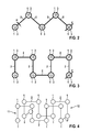
- Fig. 1 shows that the addition of the ring increases the bandwidth of the antenna from 50 MHz to 87 MHz compared to a design without the second conducting member.
- Fig. 2 illustrates a first embodiment of an antenna.
- the antenna comprises electrically conducting rings 1 as second conducting members with through going openings 3 which are electrically connected by strut-like first conducting members in the form of rods 2.
- the rods 2 form a zig-zag structure, wherein the rings 1 are accommodated at the turning points of the structure.
- Adjacent rods 2 enclose an angle of approximately 120°.
- the width w of a rod 2 is about 0.8 mm and the outer diameter d of a disc or the ring 1 is about 2 mm. Further, the diameter D of the opening 3 (see Fig. 6 and 7 with regard to the opening 33) is about 0.8 mm.
- the material of the conducting rings 1 and the rods 2 is Titanium grade 4.
- the thickness of the conducting layer forming the rods 2 and the rings 1 is about 0.1 mm.
- Fig. 3 illustrates a similar structure, wherein the angle between two adjacent rods 2 is about 90°.
- the structure of the antenna shown in Fig. 3 has the form of a square function design, wherein one conducting ring 1 is accommodated at each turning point between two adjacent rods 2.
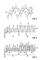
- Fig. 4 discloses a third embodiment of an antenna as shown in Fig. 4 and is similar to the structure disclosed in Fig. 3 , but the structure extends to two different planes of the device, namely a first section 11 in a first plane or first layer and a second section 12 in a second plane or second layer, which is parallel to the first plane.
- the first section 11 and the second section 12 are electrically connected by the strut (rod) 2' which runs perpendicular to the first section 11 and the second section 12.
- the embodiment disclosed in Fig. 4 has conducting members 1 in form of disks, i.e. it lacks of through going openings 3. In one or more embodiment not shown in Fig.
- the conducting members can be shaped in any kind of three dimensional forms, like spheres or ellipsoids or the like. These three dimensional forms can comprise or cannot comprise through going openings 3. In other embodiments these three dimensional forms can be solid or hollow or hollowed out. In addition these hollow or hollowed out forms can have said through going openings 3.
- Fig. 5 illustrates the structure of Fig. 2 in two parallel layers, wherein the first section 21 is accommodated in the first plane and the second section 22 in a second plane.
- the first section 21 and the second section 22 are electrically connected by the strut (rod) 2' running transversely to the first plane and the second plane.
- Fig. 6 discloses at least one embodiment of an antenna, wherein each second conducting member in form of a ring 31 with a through-going opening 33 is connected by a first conducting member in the form of a rod 32 with the next, adjacent ring 31.
- the rods 32 run parallel to each other.
- the antenna as shown in Fig. 6 comprises a first section 41 and a second section 42, wherein the rods 32 of the first section 41 are shorter than the rods 32 of the second section 42.
- Fig. 7 illustrates an embodiment of the antenna, which is similar to the antenna as shown in Fig. 6 .
- Each rod of the first section 41 of the antenna comprises in one or more embodiments one or two through-going elongated holes, slits or slots 45.
- Each slot 45 extends to the adjacent ring 31.
- Each slot 45 runs parallel to the longitudinal axis of the respective rod 32.
- the slots 45 have a width of about 0.3 mm.
- the purpose of the slots is to increase the probability of electrons taking the long path around each ring 31.
- the slots make it more difficult for electrons to travel the shorter route along the closer portions of any two consecutive rings 31. This increases the electrical length of the antenna over the design in Fig 6 which does not have the slots.
- Fig. 8 illustrates one or more embodiments, which are similar to the embodiment of Fig. 2 .
- the antenna comprises a first section 51 and a second section 52, wherein each section 51, 52 has a different resonance frequency caused by rods 2 of different length analogous to the embodiment shown in Fig. 6 and 7 thereby providing a higher bandwidth.
- the dimensions of the antenna structure of the embodiments depicted in Fig. 3 to 8 are the same as the dimensions explained in connection with the embodiment shown in Fig. 2 .
Applications Claiming Priority (1)
| Application Number | Priority Date | Filing Date | Title |
|---|---|---|---|
| US201462087817P | 2014-12-05 | 2014-12-05 |
Publications (2)
| Publication Number | Publication Date |
|---|---|
| EP3028740A1 true EP3028740A1 (fr) | 2016-06-08 |
| EP3028740B1 EP3028740B1 (fr) | 2019-04-17 |
Family
ID=54476842
Family Applications (1)
| Application Number | Title | Priority Date | Filing Date |
|---|---|---|---|
| EP15193419.7A Active EP3028740B1 (fr) | 2014-12-05 | 2015-11-06 | Antenne pour un dispositif médical implantable |
Country Status (2)
| Country | Link |
|---|---|
| US (1) | US9905916B2 (fr) |
| EP (1) | EP3028740B1 (fr) |
Cited By (3)
| Publication number | Priority date | Publication date | Assignee | Title |
|---|---|---|---|---|
| EP3492141A1 (fr) * | 2017-11-30 | 2019-06-05 | BIOTRONIK SE & Co. KG | Appareil électronique médical implantable et antenne d'émission/ de réception pour un tel appareil |
| EP3499913A1 (fr) * | 2017-12-14 | 2019-06-19 | GN Hearing A/S | Antenne dipôle à bras multiples pour instrument auditif |
| EP3626305A1 (fr) * | 2018-09-21 | 2020-03-25 | BIOTRONIK SE & Co. KG | Agencement électrique pour charge inductive et communication sans fil |
Families Citing this family (1)
| Publication number | Priority date | Publication date | Assignee | Title |
|---|---|---|---|---|
| WO2019222584A1 (fr) * | 2018-05-17 | 2019-11-21 | Curators Of The University Of Missouri | Matériau composite à constante diélectrique élevée et utilisation dans des dispositifs biocompatibles |
Citations (7)
| Publication number | Priority date | Publication date | Assignee | Title |
|---|---|---|---|---|
| US7317946B2 (en) | 2004-03-10 | 2008-01-08 | Medtronic, Inc. | Telemetry antenna for an implantable medical device |
| US7554493B1 (en) | 2002-07-08 | 2009-06-30 | Boston Scientific Neuromodulation Corporation | Folded monopole antenna for implanted medical device |
| US20090228074A1 (en) * | 2008-03-04 | 2009-09-10 | Cardiac Pacemakers, Inc. | Detachable helical antenna for implantable medical device |
| US20090248112A1 (en) * | 2005-06-07 | 2009-10-01 | Josep Mumbru | Wireless Implantable Medical Device |
| US20110134013A1 (en) * | 2003-12-22 | 2011-06-09 | Prashant Rawat | Radio frequency antenna in a header of an implantable medical device |
| US20120001812A1 (en) * | 2010-06-30 | 2012-01-05 | Medtronic, Inc. | Implantable medical device antenna |
| US20120026066A1 (en) * | 2010-07-30 | 2012-02-02 | Sarantel Limited | Antenna |
-
2015
- 2015-11-06 EP EP15193419.7A patent/EP3028740B1/fr active Active
- 2015-11-17 US US14/943,715 patent/US9905916B2/en active Active
Patent Citations (7)
| Publication number | Priority date | Publication date | Assignee | Title |
|---|---|---|---|---|
| US7554493B1 (en) | 2002-07-08 | 2009-06-30 | Boston Scientific Neuromodulation Corporation | Folded monopole antenna for implanted medical device |
| US20110134013A1 (en) * | 2003-12-22 | 2011-06-09 | Prashant Rawat | Radio frequency antenna in a header of an implantable medical device |
| US7317946B2 (en) | 2004-03-10 | 2008-01-08 | Medtronic, Inc. | Telemetry antenna for an implantable medical device |
| US20090248112A1 (en) * | 2005-06-07 | 2009-10-01 | Josep Mumbru | Wireless Implantable Medical Device |
| US20090228074A1 (en) * | 2008-03-04 | 2009-09-10 | Cardiac Pacemakers, Inc. | Detachable helical antenna for implantable medical device |
| US20120001812A1 (en) * | 2010-06-30 | 2012-01-05 | Medtronic, Inc. | Implantable medical device antenna |
| US20120026066A1 (en) * | 2010-07-30 | 2012-02-02 | Sarantel Limited | Antenna |
Non-Patent Citations (4)
| Title |
|---|
| "A Novel Low Profile Tapered Slot Antenna With Absorbing Material For Radar Imaging System", 7TH EUROPEAN CONFERENCE ON ANTENNAS AND PROPAGATION (EUCAP, 2013 |
| A. KIOURTI ET AL.: "Dual-Band Implantable Antennas For Medical Telemetry: A Fast Design Methodology And Validation For Intra-Cranial Pressure Monitoring", PROGRESS IN ELECTROMAGNETICS RESEARCH, vol. 141, 2013, pages 161 - 183, XP055263358 |
| ASIMINA KIOURTI ET AL: "DUAL-BAND IMPLANTABLE ANTENNAS FOR MEDI- CAL TELEMETRY: A FAST DESIGN METHODOLOGY AND VALIDATION FOR INTRA-CRANIAL PRESSURE MONITORING", PROGRESS IN ELECTROMAGNETICS RESEARCH, January 2013 (2013-01-01), pages 161 - 183, XP055263358, Retrieved from the Internet <URL:http://onlinewww.jpier.org/PIER/pier141/10.13051706.pdf> * |
| B. OOI ET AL.: "Novel Design of Broad-Band Stacked Patch Antenna", IEEE TRANSACTIONS ON ANTENNAS AND PROPAGATION, vol. 50, no. 10, October 2002 (2002-10-01), XP011068627 |
Cited By (8)
| Publication number | Priority date | Publication date | Assignee | Title |
|---|---|---|---|---|
| EP3492141A1 (fr) * | 2017-11-30 | 2019-06-05 | BIOTRONIK SE & Co. KG | Appareil électronique médical implantable et antenne d'émission/ de réception pour un tel appareil |
| EP3492142A1 (fr) * | 2017-11-30 | 2019-06-05 | BIOTRONIK SE & Co. KG | Appareil électronique médical implantable et antenne d'émission/ de réception pour un tel appareil |
| US10854961B2 (en) | 2017-11-30 | 2020-12-01 | Biotronik Se & Co. Kg | Implantable electronic medical device and transmit/receive antenna therefor |
| EP3499913A1 (fr) * | 2017-12-14 | 2019-06-19 | GN Hearing A/S | Antenne dipôle à bras multiples pour instrument auditif |
| EP3846499A1 (fr) * | 2017-12-14 | 2021-07-07 | GN Hearing A/S | Antenne dipôle à bras multiples pour instrument auditif |
| US11463825B2 (en) | 2017-12-14 | 2022-10-04 | Gn Hearing A/S | Multiple arm dipole antenna for hearing instrument |
| US11792582B2 (en) | 2017-12-14 | 2023-10-17 | Gn Hearing A/S | Multiple arm dipole antenna for hearing instrument |
| EP3626305A1 (fr) * | 2018-09-21 | 2020-03-25 | BIOTRONIK SE & Co. KG | Agencement électrique pour charge inductive et communication sans fil |
Also Published As
| Publication number | Publication date |
|---|---|
| US20160164170A1 (en) | 2016-06-09 |
| US9905916B2 (en) | 2018-02-27 |
| EP3028740B1 (fr) | 2019-04-17 |
Similar Documents
| Publication | Publication Date | Title |
|---|---|---|
| JP5657133B2 (ja) | 植込み型医療装置用の折り畳み式アンテナ | |
| US10029105B2 (en) | Antennas for implantable medical devices | |
| US9905916B2 (en) | Antenna and implantable medical device | |
| US20060247711A1 (en) | Telemetry antennas for implantable medical devices | |
| EP1362614A1 (fr) | Antenne à plaque implantable | |
| Luo et al. | Compact dual‐band antenna with slotted ground for implantable applications | |
| Nehra et al. | Compact dual-band Zig Zag shaped implantable antenna for biomedical devices | |
| US11616290B2 (en) | Multi-band low profile radio antenna | |
| EP3107148A1 (fr) | Dispositif médical implantable comprenant un élément électronique à haute fréquence | |
| CN210838071U (zh) | 植入式天线 | |
| Bouazizi et al. | A novel implantable Planar Inverted-F Antenna for biomedical applications | |
| Márquez | 12–18 GHz Microwave Frequency Band Microstrip Patch Antenna Design for the Radio Implant Medical Devices Application | |
| Saif et al. | A Novel Antenna Design for Implantable Medical Device | |
| CN110635239A (zh) | 用于无线生物医疗的加载渐变结构的植入式圆极化天线 |
Legal Events
| Date | Code | Title | Description |
|---|---|---|---|
| PUAI | Public reference made under article 153(3) epc to a published international application that has entered the european phase |
Free format text: ORIGINAL CODE: 0009012 |
|
| AK | Designated contracting states |
Kind code of ref document: A1 Designated state(s): AL AT BE BG CH CY CZ DE DK EE ES FI FR GB GR HR HU IE IS IT LI LT LU LV MC MK MT NL NO PL PT RO RS SE SI SK SM TR |
|
| AX | Request for extension of the european patent |
Extension state: BA ME |
|
| STAA | Information on the status of an ep patent application or granted ep patent |
Free format text: STATUS: REQUEST FOR EXAMINATION WAS MADE |
|
| 17P | Request for examination filed |
Effective date: 20161115 |
|
| RBV | Designated contracting states (corrected) |
Designated state(s): AL AT BE BG CH CY CZ DE DK EE ES FI FR GB GR HR HU IE IS IT LI LT LU LV MC MK MT NL NO PL PT RO RS SE SI SK SM TR |
|
| STAA | Information on the status of an ep patent application or granted ep patent |
Free format text: STATUS: EXAMINATION IS IN PROGRESS |
|
| 17Q | First examination report despatched |
Effective date: 20171219 |
|
| GRAP | Despatch of communication of intention to grant a patent |
Free format text: ORIGINAL CODE: EPIDOSNIGR1 |
|
| STAA | Information on the status of an ep patent application or granted ep patent |
Free format text: STATUS: GRANT OF PATENT IS INTENDED |
|
| INTG | Intention to grant announced |
Effective date: 20181106 |
|
| RIC1 | Information provided on ipc code assigned before grant |
Ipc: A61N 1/372 20060101AFI20181023BHEP Ipc: H01Q 1/22 20060101ALI20181023BHEP Ipc: A61N 1/375 20060101ALN20181023BHEP Ipc: H01Q 1/27 20060101ALI20181023BHEP Ipc: H01Q 9/42 20060101ALI20181023BHEP Ipc: H01Q 1/36 20060101ALI20181023BHEP |
|
| GRAS | Grant fee paid |
Free format text: ORIGINAL CODE: EPIDOSNIGR3 |
|
| GRAA | (expected) grant |
Free format text: ORIGINAL CODE: 0009210 |
|
| STAA | Information on the status of an ep patent application or granted ep patent |
Free format text: STATUS: THE PATENT HAS BEEN GRANTED |
|
| AK | Designated contracting states |
Kind code of ref document: B1 Designated state(s): AL AT BE BG CH CY CZ DE DK EE ES FI FR GB GR HR HU IE IS IT LI LT LU LV MC MK MT NL NO PL PT RO RS SE SI SK SM TR |
|
| REG | Reference to a national code |
Ref country code: GB Ref legal event code: FG4D |
|
| REG | Reference to a national code |
Ref country code: CH Ref legal event code: EP |
|
| REG | Reference to a national code |
Ref country code: DE Ref legal event code: R096 Ref document number: 602015028384 Country of ref document: DE |
|
| REG | Reference to a national code |
Ref country code: AT Ref legal event code: REF Ref document number: 1120904 Country of ref document: AT Kind code of ref document: T Effective date: 20190515 Ref country code: IE Ref legal event code: FG4D |
|
| REG | Reference to a national code |
Ref country code: NL Ref legal event code: MP Effective date: 20190417 |
|
| REG | Reference to a national code |
Ref country code: LT Ref legal event code: MG4D |
|
| PG25 | Lapsed in a contracting state [announced via postgrant information from national office to epo] |
Ref country code: NL Free format text: LAPSE BECAUSE OF FAILURE TO SUBMIT A TRANSLATION OF THE DESCRIPTION OR TO PAY THE FEE WITHIN THE PRESCRIBED TIME-LIMIT Effective date: 20190417 |
|
| PG25 | Lapsed in a contracting state [announced via postgrant information from national office to epo] |
Ref country code: AL Free format text: LAPSE BECAUSE OF FAILURE TO SUBMIT A TRANSLATION OF THE DESCRIPTION OR TO PAY THE FEE WITHIN THE PRESCRIBED TIME-LIMIT Effective date: 20190417 Ref country code: ES Free format text: LAPSE BECAUSE OF FAILURE TO SUBMIT A TRANSLATION OF THE DESCRIPTION OR TO PAY THE FEE WITHIN THE PRESCRIBED TIME-LIMIT Effective date: 20190417 Ref country code: FI Free format text: LAPSE BECAUSE OF FAILURE TO SUBMIT A TRANSLATION OF THE DESCRIPTION OR TO PAY THE FEE WITHIN THE PRESCRIBED TIME-LIMIT Effective date: 20190417 Ref country code: LT Free format text: LAPSE BECAUSE OF FAILURE TO SUBMIT A TRANSLATION OF THE DESCRIPTION OR TO PAY THE FEE WITHIN THE PRESCRIBED TIME-LIMIT Effective date: 20190417 Ref country code: SE Free format text: LAPSE BECAUSE OF FAILURE TO SUBMIT A TRANSLATION OF THE DESCRIPTION OR TO PAY THE FEE WITHIN THE PRESCRIBED TIME-LIMIT Effective date: 20190417 Ref country code: PT Free format text: LAPSE BECAUSE OF FAILURE TO SUBMIT A TRANSLATION OF THE DESCRIPTION OR TO PAY THE FEE WITHIN THE PRESCRIBED TIME-LIMIT Effective date: 20190817 Ref country code: HR Free format text: LAPSE BECAUSE OF FAILURE TO SUBMIT A TRANSLATION OF THE DESCRIPTION OR TO PAY THE FEE WITHIN THE PRESCRIBED TIME-LIMIT Effective date: 20190417 Ref country code: NO Free format text: LAPSE BECAUSE OF FAILURE TO SUBMIT A TRANSLATION OF THE DESCRIPTION OR TO PAY THE FEE WITHIN THE PRESCRIBED TIME-LIMIT Effective date: 20190717 |
|
| PG25 | Lapsed in a contracting state [announced via postgrant information from national office to epo] |
Ref country code: LV Free format text: LAPSE BECAUSE OF FAILURE TO SUBMIT A TRANSLATION OF THE DESCRIPTION OR TO PAY THE FEE WITHIN THE PRESCRIBED TIME-LIMIT Effective date: 20190417 Ref country code: PL Free format text: LAPSE BECAUSE OF FAILURE TO SUBMIT A TRANSLATION OF THE DESCRIPTION OR TO PAY THE FEE WITHIN THE PRESCRIBED TIME-LIMIT Effective date: 20190417 Ref country code: GR Free format text: LAPSE BECAUSE OF FAILURE TO SUBMIT A TRANSLATION OF THE DESCRIPTION OR TO PAY THE FEE WITHIN THE PRESCRIBED TIME-LIMIT Effective date: 20190718 Ref country code: BG Free format text: LAPSE BECAUSE OF FAILURE TO SUBMIT A TRANSLATION OF THE DESCRIPTION OR TO PAY THE FEE WITHIN THE PRESCRIBED TIME-LIMIT Effective date: 20190717 Ref country code: RS Free format text: LAPSE BECAUSE OF FAILURE TO SUBMIT A TRANSLATION OF THE DESCRIPTION OR TO PAY THE FEE WITHIN THE PRESCRIBED TIME-LIMIT Effective date: 20190417 |
|
| REG | Reference to a national code |
Ref country code: AT Ref legal event code: MK05 Ref document number: 1120904 Country of ref document: AT Kind code of ref document: T Effective date: 20190417 |
|
| PG25 | Lapsed in a contracting state [announced via postgrant information from national office to epo] |
Ref country code: IS Free format text: LAPSE BECAUSE OF FAILURE TO SUBMIT A TRANSLATION OF THE DESCRIPTION OR TO PAY THE FEE WITHIN THE PRESCRIBED TIME-LIMIT Effective date: 20190817 |
|
| REG | Reference to a national code |
Ref country code: DE Ref legal event code: R097 Ref document number: 602015028384 Country of ref document: DE |
|
| PG25 | Lapsed in a contracting state [announced via postgrant information from national office to epo] |
Ref country code: AT Free format text: LAPSE BECAUSE OF FAILURE TO SUBMIT A TRANSLATION OF THE DESCRIPTION OR TO PAY THE FEE WITHIN THE PRESCRIBED TIME-LIMIT Effective date: 20190417 Ref country code: RO Free format text: LAPSE BECAUSE OF FAILURE TO SUBMIT A TRANSLATION OF THE DESCRIPTION OR TO PAY THE FEE WITHIN THE PRESCRIBED TIME-LIMIT Effective date: 20190417 Ref country code: CZ Free format text: LAPSE BECAUSE OF FAILURE TO SUBMIT A TRANSLATION OF THE DESCRIPTION OR TO PAY THE FEE WITHIN THE PRESCRIBED TIME-LIMIT Effective date: 20190417 Ref country code: EE Free format text: LAPSE BECAUSE OF FAILURE TO SUBMIT A TRANSLATION OF THE DESCRIPTION OR TO PAY THE FEE WITHIN THE PRESCRIBED TIME-LIMIT Effective date: 20190417 Ref country code: DK Free format text: LAPSE BECAUSE OF FAILURE TO SUBMIT A TRANSLATION OF THE DESCRIPTION OR TO PAY THE FEE WITHIN THE PRESCRIBED TIME-LIMIT Effective date: 20190417 Ref country code: SK Free format text: LAPSE BECAUSE OF FAILURE TO SUBMIT A TRANSLATION OF THE DESCRIPTION OR TO PAY THE FEE WITHIN THE PRESCRIBED TIME-LIMIT Effective date: 20190417 |
|
| PLBE | No opposition filed within time limit |
Free format text: ORIGINAL CODE: 0009261 |
|
| STAA | Information on the status of an ep patent application or granted ep patent |
Free format text: STATUS: NO OPPOSITION FILED WITHIN TIME LIMIT |
|
| PG25 | Lapsed in a contracting state [announced via postgrant information from national office to epo] |
Ref country code: IT Free format text: LAPSE BECAUSE OF FAILURE TO SUBMIT A TRANSLATION OF THE DESCRIPTION OR TO PAY THE FEE WITHIN THE PRESCRIBED TIME-LIMIT Effective date: 20190417 Ref country code: SM Free format text: LAPSE BECAUSE OF FAILURE TO SUBMIT A TRANSLATION OF THE DESCRIPTION OR TO PAY THE FEE WITHIN THE PRESCRIBED TIME-LIMIT Effective date: 20190417 |
|
| 26N | No opposition filed |
Effective date: 20200120 |
|
| PG25 | Lapsed in a contracting state [announced via postgrant information from national office to epo] |
Ref country code: TR Free format text: LAPSE BECAUSE OF FAILURE TO SUBMIT A TRANSLATION OF THE DESCRIPTION OR TO PAY THE FEE WITHIN THE PRESCRIBED TIME-LIMIT Effective date: 20190417 |
|
| PG25 | Lapsed in a contracting state [announced via postgrant information from national office to epo] |
Ref country code: SI Free format text: LAPSE BECAUSE OF FAILURE TO SUBMIT A TRANSLATION OF THE DESCRIPTION OR TO PAY THE FEE WITHIN THE PRESCRIBED TIME-LIMIT Effective date: 20190417 |
|
| PG25 | Lapsed in a contracting state [announced via postgrant information from national office to epo] |
Ref country code: MC Free format text: LAPSE BECAUSE OF FAILURE TO SUBMIT A TRANSLATION OF THE DESCRIPTION OR TO PAY THE FEE WITHIN THE PRESCRIBED TIME-LIMIT Effective date: 20190417 Ref country code: LU Free format text: LAPSE BECAUSE OF NON-PAYMENT OF DUE FEES Effective date: 20191106 |
|
| REG | Reference to a national code |
Ref country code: BE Ref legal event code: MM Effective date: 20191130 |
|
| GBPC | Gb: european patent ceased through non-payment of renewal fee |
Effective date: 20191106 |
|
| PG25 | Lapsed in a contracting state [announced via postgrant information from national office to epo] |
Ref country code: FR Free format text: LAPSE BECAUSE OF NON-PAYMENT OF DUE FEES Effective date: 20191130 Ref country code: GB Free format text: LAPSE BECAUSE OF NON-PAYMENT OF DUE FEES Effective date: 20191106 |
|
| PG25 | Lapsed in a contracting state [announced via postgrant information from national office to epo] |
Ref country code: BE Free format text: LAPSE BECAUSE OF NON-PAYMENT OF DUE FEES Effective date: 20191130 |
|
| PG25 | Lapsed in a contracting state [announced via postgrant information from national office to epo] |
Ref country code: CY Free format text: LAPSE BECAUSE OF FAILURE TO SUBMIT A TRANSLATION OF THE DESCRIPTION OR TO PAY THE FEE WITHIN THE PRESCRIBED TIME-LIMIT Effective date: 20190417 |
|
| PG25 | Lapsed in a contracting state [announced via postgrant information from national office to epo] |
Ref country code: MT Free format text: LAPSE BECAUSE OF FAILURE TO SUBMIT A TRANSLATION OF THE DESCRIPTION OR TO PAY THE FEE WITHIN THE PRESCRIBED TIME-LIMIT Effective date: 20190417 Ref country code: HU Free format text: LAPSE BECAUSE OF FAILURE TO SUBMIT A TRANSLATION OF THE DESCRIPTION OR TO PAY THE FEE WITHIN THE PRESCRIBED TIME-LIMIT; INVALID AB INITIO Effective date: 20151106 |
|
| PG25 | Lapsed in a contracting state [announced via postgrant information from national office to epo] |
Ref country code: MK Free format text: LAPSE BECAUSE OF FAILURE TO SUBMIT A TRANSLATION OF THE DESCRIPTION OR TO PAY THE FEE WITHIN THE PRESCRIBED TIME-LIMIT Effective date: 20190417 |
|
| P01 | Opt-out of the competence of the unified patent court (upc) registered |
Effective date: 20230613 |
|
| PGFP | Annual fee paid to national office [announced via postgrant information from national office to epo] |
Ref country code: IE Payment date: 20231117 Year of fee payment: 9 Ref country code: DE Payment date: 20231120 Year of fee payment: 9 Ref country code: CH Payment date: 20231201 Year of fee payment: 9 |