EP3028642A1 - Distal end part of ultrasonic endoscope - Google Patents
Distal end part of ultrasonic endoscope Download PDFInfo
- Publication number
- EP3028642A1 EP3028642A1 EP14852522.3A EP14852522A EP3028642A1 EP 3028642 A1 EP3028642 A1 EP 3028642A1 EP 14852522 A EP14852522 A EP 14852522A EP 3028642 A1 EP3028642 A1 EP 3028642A1
- Authority
- EP
- European Patent Office
- Prior art keywords
- ultrasound
- wiring substrate
- wiring
- section
- distal end
- Prior art date
- Legal status (The legal status is an assumption and is not a legal conclusion. Google has not performed a legal analysis and makes no representation as to the accuracy of the status listed.)
- Withdrawn
Links
Images




Classifications
-
- A—HUMAN NECESSITIES
- A61—MEDICAL OR VETERINARY SCIENCE; HYGIENE
- A61B—DIAGNOSIS; SURGERY; IDENTIFICATION
- A61B8/00—Diagnosis using ultrasonic, sonic or infrasonic waves
- A61B8/12—Diagnosis using ultrasonic, sonic or infrasonic waves in body cavities or body tracts, e.g. by using catheters
-
- A—HUMAN NECESSITIES
- A61—MEDICAL OR VETERINARY SCIENCE; HYGIENE
- A61B—DIAGNOSIS; SURGERY; IDENTIFICATION
- A61B1/00—Instruments for performing medical examinations of the interior of cavities or tubes of the body by visual or photographical inspection, e.g. endoscopes; Illuminating arrangements therefor
- A61B1/04—Instruments for performing medical examinations of the interior of cavities or tubes of the body by visual or photographical inspection, e.g. endoscopes; Illuminating arrangements therefor combined with photographic or television appliances
- A61B1/05—Instruments for performing medical examinations of the interior of cavities or tubes of the body by visual or photographical inspection, e.g. endoscopes; Illuminating arrangements therefor combined with photographic or television appliances characterised by the image sensor, e.g. camera, being in the distal end portion
-
- A—HUMAN NECESSITIES
- A61—MEDICAL OR VETERINARY SCIENCE; HYGIENE
- A61B—DIAGNOSIS; SURGERY; IDENTIFICATION
- A61B8/00—Diagnosis using ultrasonic, sonic or infrasonic waves
- A61B8/44—Constructional features of the ultrasonic, sonic or infrasonic diagnostic device
- A61B8/4444—Constructional features of the ultrasonic, sonic or infrasonic diagnostic device related to the probe
-
- A—HUMAN NECESSITIES
- A61—MEDICAL OR VETERINARY SCIENCE; HYGIENE
- A61B—DIAGNOSIS; SURGERY; IDENTIFICATION
- A61B8/00—Diagnosis using ultrasonic, sonic or infrasonic waves
- A61B8/44—Constructional features of the ultrasonic, sonic or infrasonic diagnostic device
- A61B8/4444—Constructional features of the ultrasonic, sonic or infrasonic diagnostic device related to the probe
- A61B8/445—Details of catheter construction
-
- A—HUMAN NECESSITIES
- A61—MEDICAL OR VETERINARY SCIENCE; HYGIENE
- A61B—DIAGNOSIS; SURGERY; IDENTIFICATION
- A61B1/00—Instruments for performing medical examinations of the interior of cavities or tubes of the body by visual or photographical inspection, e.g. endoscopes; Illuminating arrangements therefor
- A61B1/012—Instruments for performing medical examinations of the interior of cavities or tubes of the body by visual or photographical inspection, e.g. endoscopes; Illuminating arrangements therefor characterised by internal passages or accessories therefor
- A61B1/018—Instruments for performing medical examinations of the interior of cavities or tubes of the body by visual or photographical inspection, e.g. endoscopes; Illuminating arrangements therefor characterised by internal passages or accessories therefor for receiving instruments
-
- A—HUMAN NECESSITIES
- A61—MEDICAL OR VETERINARY SCIENCE; HYGIENE
- A61B—DIAGNOSIS; SURGERY; IDENTIFICATION
- A61B1/00—Instruments for performing medical examinations of the interior of cavities or tubes of the body by visual or photographical inspection, e.g. endoscopes; Illuminating arrangements therefor
- A61B1/04—Instruments for performing medical examinations of the interior of cavities or tubes of the body by visual or photographical inspection, e.g. endoscopes; Illuminating arrangements therefor combined with photographic or television appliances
-
- A—HUMAN NECESSITIES
- A61—MEDICAL OR VETERINARY SCIENCE; HYGIENE
- A61B—DIAGNOSIS; SURGERY; IDENTIFICATION
- A61B1/00—Instruments for performing medical examinations of the interior of cavities or tubes of the body by visual or photographical inspection, e.g. endoscopes; Illuminating arrangements therefor
- A61B1/06—Instruments for performing medical examinations of the interior of cavities or tubes of the body by visual or photographical inspection, e.g. endoscopes; Illuminating arrangements therefor with illuminating arrangements
Definitions
- the present invention relates to an ultrasound endoscope distal end portion disposed at a distal end of an insertion portion of an ultrasound endoscope.
- Ultrasound diagnosis which irradiates a subject with ultrasound, images and diagnoses a state of a body interior from an echo signal is becoming widespread.
- One of diagnostic apparatuses used for such ultrasound diagnosis is an ultrasound endoscope system.
- An ultrasound endoscope of the ultrasound endoscope system includes an ultrasound transducer unit disposed at a distal end portion of an insertion portion which is inserted into the body.
- the ultrasound transducer unit has a function of converting an electrical signal to ultrasound, transmitting the ultrasound into the body, receiving the ultrasound reflected in the body and converting the ultrasound to an electrical signal.
- Japanese Patent Application Laid-Open Publication No. 2006- 166985 discloses an ultrasound probe for diagnosis in a body cavity which is inserted into a body cavity and in order to reduce the diameter of a distal end uses a technique of reducing harmful effects caused by using a wiring cable.
- the conventional ultrasound probe for diagnosis in a body cavity is disclosed as an ultrasound endoscope provided with a convex ultrasound transducer and an image pickup apparatus.
- a wiring which is a signal line connected to the ultrasound transducer is arranged in the insertion portion from the center of the ultrasound transducer.
- the wiring layout of the conventional ultrasound endoscope imposes considerable limits on the arrangement of components in the distal end portion such as a forceps opening portion, a light guide, an image pickup unit, an image pickup cable (or image guide) or the like provided in the distal end portion or the like of the ultrasound endoscope and reduces the degree of freedom of design of the distal end portion, which results in a problem of preventing the distal end portion from being downsized.
- wires extending from the ultrasound transducer are individually electrically connected to a plurality of piezoelectric elements of a piezoelectric element array provided in the ultrasound transducer, and therefore a plurality of extremely thin wires are bundled into a cable. Especially when stress is generated in a wiring connection portion where a plurality of wires are connected, wire breakage or the like may occur, causing a problem such as a failure.
- the present invention has therefore been implemented in view of the above-described problems, and it is an object of the present invention to provide a ultrasound endoscope distal end portion that can improve a degree of freedom in an arrangement of components for various functions, reduce the size of the components, prevent stress from occurring on a wiring connection portion to which wires for driving a plurality of ultrasound elements are connected and thereby improve resistance.
- An ultrasound endoscope distal end portion includes an ultrasound transducer section that has an ultrasound transmission/reception surface that transmits/receives ultrasound and a back surface positioned on a side opposite to the ultrasound transmission/reception surface, a wiring substrate that has a tabular shape, is arranged non-parallel to the back surface and is electrically connected to the ultrasound transducer section, a backing member that is disposed on the back surface and fills the wiring substrate so that part of the wiring substrate is exposed, a plurality of wires that include, when a direction toward the ultrasound transmission/reception surface viewed from the backing member is assumed to be an upward direction, a direction opposite to the upward direction is assumed to be a backward direction and a direction crossing a direction from the upward direction toward the backward direction is assumed to be a sideward direction, a bending portion that is bent toward the sideward direction after being connected to the wiring substrate from the upward direction toward the backward direction, a holding frame that holds the backing member by surrounding a whole circumference on
- an ultrasound endoscope distal end portion that improves the degree of freedom in an arrangement of components for various functions, can thereby downsize the components, prevent stress from occurring on the wiring connection section to which wires for driving a plurality of ultrasound elements are connected and improve resistance.
- drawings based on the following embodiment are schematic drawings and a relationship between a thickness and a width of each component and a ratio of thickness among the respective components or the like are different from those of the actual components, and a dimensional relationship and ratio may differ among the drawings.
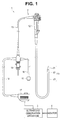
- Fig. 1 is a plan view illustrating an overall configuration of an ultrasound endoscope
- Fig. 2 is a perspective view illustrating a configuration of an ultrasound endoscope distal end portion
- Fig. 3 is a top view illustrating the configuration of the ultrasound endoscope distal end portion
- Fig. 4 is a side view illustrating the configuration of the ultrasound endoscope distal end portion
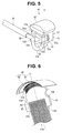
- Fig. 5 is a perspective view illustrating a configuration of an ultrasound transducer unit
- Fig. 1 is a plan view illustrating an overall configuration of an ultrasound endoscope
- Fig. 2 is a perspective view illustrating a configuration of an ultrasound endoscope distal end portion
- Fig. 3 is a top view illustrating the configuration of the ultrasound endoscope distal end portion
- Fig. 4 is a side view illustrating the configuration of the ultrasound endoscope distal end portion
- Fig. 5 is a perspective view illustrating a configuration of an ultrasound transducer unit
- FIG. 6 is a perspective view illustrating a configuration of an ultrasound transducer section and a wiring substrate provided in the ultrasound transducer unit
- Fig. 7 is a perspective view illustrating a configuration in which the ultrasound transducer section is provided with a backing member holding frame and a backing member in which part of the wiring substrate is embedded
- Fig. 8 is an exploded perspective view illustrating a configuration in which wiring holders are disposed so as to sandwich the wiring substrate
- Fig. 9 is an exploded perspective view illustrating a state in which the wiring substrate fits with the first wiring holder
- Fig. 10 is a perspective view illustrating a configuration in which an adhesive is provided to fix the backing member holding frame and the wiring holder so as to cover the backing member
- Fig. 11 is an arrow view viewed from the arrow X1 direction in Fig. 10
- Fig. 12 is a perspective view illustrating a configuration in which the wiring holders are provided so as to sandwich the wiring substrate
- Fig. 13 is a perspective view illustrating a configuration of the ultrasound transducer unit provided with an acoustic lens
- Fig. 14 is a perspective view illustrating a configuration of the ultrasound transducer unit provided with the acoustic lens and viewed from an angle different from that in Fig. 13
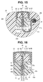
- Fig. 15 is a cross-sectional view illustrating a state in which the ultrasound transducer unit is attached to a distal end cover
- Fig. 16 is a cross-sectional view illustrating a configuration of wiring holders according to a first modification
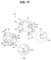
- Fig. 17 is an exploded perspective view illustrating a configuration of wiring holders according to a second modification.
- an ultrasound endoscope system 1 is configured by mainly including an ultrasound endoscope 2, an ultrasound observation apparatus 3 and a monitor 4.
- the ultrasound endoscope 2 is provided with an elongated insertion portion 11 which is inserted into the body, an operation portion 12 disposed at a proximal end of the insertion portion 11 and a universal cord 13 that extends from the operation portion 12.
- a light source connector 14 connected to a light source apparatus is disposed at a proximal end portion of the universal cord 13.
- a cable 16 connected to a camera control unit (not shown) via an electrical connector 15 and a cable 18 connected to the ultrasound observation apparatus 3 via an ultrasound connector 17 extend from the light source connector 14. Note that the monitor 4 that displays ultrasound images is connected to the ultrasound observation apparatus 3.
- the insertion portion 11 is configured by consecutively connecting, in order from the distal end side, a distal end constituting portion (hereinafter referred to as "distal end portion") 21 as an ultrasound endoscope distal end portion, a bending portion 22 located at a back end of the distal end portion 21, a flexible tube 23 which is thin, long and flexible, located at a back end of the bending portion 22 and extending to the operation portion 12.
- distal end portion 21 a distal end constituting portion (hereinafter referred to as "distal end portion") 21 as an ultrasound endoscope distal end portion
- a bending portion 22 located at a back end of the distal end portion 21
- a flexible tube 23 which is thin, long and flexible, located at a back end of the bending portion 22 and extending to the operation portion 12.
- distal end portion 21 of the present embodiment will be described in detail below.
- the distal end portion 21 of the ultrasound endoscope 2 is made up of a metallic distal end rigid portion 24 cladded with a synthetic resin distal end cover 25.
- An ultrasound transducer unit 40 is disposed on one surface of the distal end portion 21 which is a top surface of the distal end cover 25 orthogonal to an insertion axis X of the insertion portion 11, as an ultrasound transducer provided with a plurality of (here two) first and second raising stands 26 and 27, a plurality of (here two) first and second channel opening portions 28 and 29, an optical observation window 31, an optical illuminating window 32 and a plurality of ultrasound elements.
- the ultrasound transducer unit 40 here is of a convex scanning type in which a plurality of ultrasound elements are arranged in a convex bent shape.
- the distal end portion 21 is provided with the ultrasound transducer unit 40, the first raising stand 26, the first channel opening portion 28, the second raising stand 27 and the second channel opening portion 29, arranged side by side in order from the distal end along the insertion axis X.
- the ultrasound transducer unit 40 is provided on the distal end side and the first raising stand 26, the first channel opening portion 28, the second raising stand 27 and the second channel opening portion 29 are arranged side by side on a straight line along the insertion axis X on the proximal end.
- first raising stand 26 and the second raising stand 27 are provided so as to be freely rotatable in a concave portion formed in the distal end rigid portion 24 of the distal end portion 21.
- the first raising stand 26 and the second raising stand 27 are operated to rotate through operation of a raising lever (not shown) provided on the operation portion 12.
- a raising lever (not shown) provided on the operation portion 12.
- a detailed configuration in which the first raising stand 26 and the second raising stand 27 rise and fall is the same as the conventional one, and so description thereof is omitted.
- the first raising stand 26 or the second raising stand 27 is operated to rotate in the raising direction, and can thereby raise/lead out a treatment instrument such as a contrast imaging tube or a puncture needle projecting from the first channel opening portion 28 or the second channel opening portion 29 in a direction orthogonal to the insertion axis X.
- a treatment instrument such as a contrast imaging tube or a puncture needle projecting from the first channel opening portion 28 or the second channel opening portion 29 in a direction orthogonal to the insertion axis X.
- first channel opening portion 28 and the second channel opening portion 29 constitute openings on the distal end side of two treatment instrument channels (not shown) disposed from the distal end portion 21 to the insertion portion 11 and the operation portion 12.
- the two treatment instrument channels are connected to a treatment instrument insertion port (not shown) provided in the operation portion 12 and a treatment instrument is introduced from the treatment instrument insertion port.
- the optical observation window 31 here constitutes an optical observation system with respect to an image pickup unit (not shown) provided with a solid image pickup device as image pickup means disposed in the distal end portion 21. That is, the image pickup unit incorporated in the distal end portion 21 is disposed on the back side of the optical observation window 31.
- the image pickup means of the ultrasound endoscope 2 is not limited to the image pickup unit, but may also have a configuration using an image guide.
- illumination means of the ultrasound endoscope 2 is not limited to the light guide that transmits the illuminating light from the light source apparatus, but may also have a configuration using illumination means such as LED illumination.
- the ultrasound endoscope 2 of the present embodiment adopts a configuration in which the ultrasound transducer unit 40 is arranged at the distal end of the distal end portion 21 of the insertion portion 11, and the first raising stand 26, the first channel opening portion 28, the second raising stand 27 and the second channel opening portion 29 are linearly arranged side by side in order on the hand side, which is the proximal end side on the insertion axis X as the central axis of the distal end portion 21, so as to improve operability of treatment using a treatment instrument such as a contrast imaging tube or a puncture needle under an ultrasound image guide by the ultrasound transducer unit 40.
- a treatment instrument such as a contrast imaging tube or a puncture needle under an ultrasound image guide by the ultrasound transducer unit 40.
- the ultrasound endoscope 2 provides the respective centers of the first raising stand 26, the first channel opening portion 28, the second raising stand 27 and the second channel opening portion 29 on a plane substantially identical to an ultrasound scanning plane under the ultrasound image guide by the ultrasound transducer unit 40, thereby causes a treatment instrument such as a contrast imaging tube or a puncture needle led out from the first channel opening portion 28 or the second channel opening portion 29 to rise toward the ultrasound scanning plane by the first raising stand 26 or the second raising stand 27 to ensure that the treatment instrument is reflected under the ultrasound image.
- a treatment instrument such as a contrast imaging tube or a puncture needle led out from the first channel opening portion 28 or the second channel opening portion 29 to rise toward the ultrasound scanning plane by the first raising stand 26 or the second raising stand 27 to ensure that the treatment instrument is reflected under the ultrasound image.
- an ultrasound cable 41 extends backward from the ultrasound transducer unit 40 provided at the distal end.
- the ultrasound cable 41 constitutes a drive cable that drives the ultrasound transducer unit 40 and includes a bending portion where an ultrasound cable wire bundle 41 a extends from below the ultrasound transducer unit 40 inside the distal end cover 25, is bent toward one side of the ultrasound transducer unit 40, and then further bent backward. Furthermore, the ultrasound cable 41 is configured by covering the ultrasound cable wire bundle 41 a, which is bent and extends backward, with an external coat.
- the ultrasound cable 41 is inserted through the insertion portion 11, the operation portion 12, the universal cord 13, the light source connector 14 and the cable 18, and extends to the ultrasound connector 17 connected to the ultrasound observation apparatus 3.
- the ultrasound cable 41 configured in this way is offset toward one side from the center of the ultrasound transducer unit 40 and extends from the back end of the edge portion of the distal end cover 25 directly into the bending portion 22 of the insertion portion 11.
- the ultrasound cable 41 is not inserted into the distal end rigid portion 24 covered with the distal end cover 25 in the distal end portion 21 but is inserted through one side of the distal end cover 25.
- the ultrasound cable 41 is placed in a notch 24b formed on one side of a proximal end connection portion 24a of the distal end rigid portion 24, is bent toward the center direction (inner diameter direction) of the insertion portion 11 via the notch 24b and inserted into the bending portion 22.
- the ultrasound cable 41 extends along one side in the distal end cover 25 in the distal end portion 21, is then inserted into the bending portion 22 from the notch 24b of the proximal end connection portion 24a provided at the back end of the distal end rigid portion 24 and placed in the insertion portion 11.
- a bending piece (not shown) at the distalmost end of the bending portion 22 is connected to the proximal end connection portion 24a of the distal end rigid portion 24.
- the ultrasound cable 41 of the distal end portion 21 is offset toward the one side direction from the center of the ultrasound transducer unit 40, inserted at a position deviated from the insertion axis X and not provided on the plane substantially identical to the ultrasound scanning plane of the ultrasound transducer unit 40.
- a resin e.g., non-conductive silicone resin acoustic lens 42 is molded into a convex shape as an exposed portion.
- the ultrasound transducer unit 40 includes a non-conductive wiring holder 50 made up of a first wiring holder 51 and a second wiring holder 52 that fixes a wiring substrate 43 so as to cover both sides thereof and cover a wiring connection portion and a ground connection portion, which will be described later, of the wiring substrate 43 to which a plurality of wires of the ultrasound cable wire bundle 41a of the ultrasound cable 41 are connected, as a restricting section that fits with and restricts the wiring substrate 43 so as not to move.
- the configuration of the wiring holder 50 will be described later in detail.
- the respective wires of the ultrasound cable wire bundle 41 a are connected side by side in a direction substantially orthogonal to a transducer sound axis U so as to extend toward one side which is a downward side where the wires become non-parallel to each other as shown in Fig. 6 .
- the respective wires of the ultrasound cable wire bundle 41a are coaxial cables and are connected to both sides of the wiring substrate 43.
- the wiring substrate 43 includes a wiring connection portion 44 formed with inner conductors of the respective coaxial cables of the ultrasound cable wire bundle 41 a connected by solder and a ground connection portion 45 formed with outer conductors of the respective coaxial cables connected by solder, and a plurality of connection lands (not shown) are formed in the wiring connection portion 44 and the ground connection portion 45.
- the wiring connection portion 44 and the ground connection portion 45 are arranged side by side toward a direction substantially orthogonal to the transducer sound axis U along the plane of the wiring substrate 43. Note that the wiring connection portion 44 and the ground connection portion 45 are provided on both sides of the wiring substrate 43.
- the plurality of coaxial cables of the ultrasound cable wire bundle 41 a are connected at the wiring connection portion 44 and the ground connection portion 45 so as to be arranged side by side in the direction substantially orthogonal to the transducer sound axis U along the plane of the wiring substrate 43 on both sides of the wiring substrate 43.
- the length of the wiring substrate 43 in the direction along the transducer sound axis U can be reduced.
- the wiring substrate 43 is provided with four concave portions 43a, 43b, 43c and 43d which become a wiring substrate side fitting portion which is formed by cutting out both sides on the upper side halfway and two corners on the lower side as the configuration for positioning when the wiring substrate 43 is fixed to the above-described wiring holder 50.
- the roles of the four concave portions 43a, 43b, 43c and 43d will be described later.
- the wiring substrate 43 is provided with a wiring group 62a in an arc-shaped upper edge portion formed on the top side.
- the wiring group 62a is electrically connected to a plurality of connection lands and wiring patterns of the wiring connection portion 44 and the ground connection portion 45 to which the respective coaxial cables of the ultrasound cable wire bundle 41 a are connected and is a plurality of wires connected to respective piezoelectric elements of a piezoelectric element array 62.
- the piezoelectric element array 62 is provided on the back (reverse) side of a tabular acoustic matching layer 61 having an arc-shaped cross section.
- the acoustic matching layer 61 and the piezoelectric element array 62 constitute an ultrasound transducer section 60.
- the surface of the acoustic matching layer 61 constitutes an ultrasound transmission/reception surface to transmit/receive ultrasound.
- a backing member holding frame 63 which is a tabular frame body disposed so as to surround the acoustic matching layer 61 along the edge portion thereof on the back (reverse) side on which the piezoelectric element array 62 is provided as shown in Fig. 7 is fixed to the acoustic matching layer 61 using an adhesive.
- a backing member 64 made of a non-conductive member is provided in the space formed of the back (reverse) side of the acoustic matching layer 61 and the backing member holding frame 63.
- the backing member 64 is arranged by covering part of the wiring substrate 43 from the top to a halfway position, the piezoelectric element array 62 and the wiring group 62a extending from the wiring substrate 43 connected to the piezoelectric element array so as to embed these parts, and the entire side face thereof is held by the backing member holding frame 63.
- the first wiring holder 51 and the second wiring holder 52 of the aforementioned non-conductive wiring holder 50 fit with the wiring substrate 43 to which the ultrasound transducer section 60 is fixed via the backing member 64 so as to sandwich both sides of the portion of the wiring substrate 43 below the portion thereof embedded in the backing member 64 as shown in Fig. 8 to Fig. 10 .
- the first wiring holder 51 and the second wiring holder 52 fit with each other and are fixed so as to sandwich the wiring substrate 43 from both sides in such a way as to cover the wiring connection portion 44 and the ground connection portion 45 to which the plurality of coaxial cables of the ultrasound cable wire bundle 41 a are connected, which are respectively provided linearly on both sides of the wiring substrate 43.
- a non-conductive plastic material, a ceramic material, or a material including a metal coated with a non-conductive coat or the like is used for both the first wiring holder 51 and the second wiring holder 52 of the wiring holder 50.
- the configuration of the wiring holder 50 will be described in detail below.
- the first wiring holder 51 of the wiring holder 50 has four fitting protruding portions 51 a as first restricting section side fitting portions that extend from the four corners of the plane opposite to one plane of the wiring substrate 43.
- each of the four fitting protruding portions 51a fits with one of the four concave portions 43a, 43b, 43c and 43d as the wiring substrate side fitting portion of the wiring substrate 43 located at the corresponding position as shown in Fig. 9 .
- the wiring substrate 43 is located at a predetermined position of the first wiring holder 51 held by the four fitting protruding portions 51a. That is, the wiring substrate 43 is restricted so as not to move at a predetermined position of the first wiring holder 51.
- the second wiring holder 52 of the wiring holder 50 has four fitting concave portions 52a as second restricting member side fitting portions formed by being cut out in the four corners and a concave portion 52b is formed on the side opposite to the plane facing one plane of the wiring substrate 43.
- the wiring substrate 43 fits with the first wiring holder 51 first.
- each of the four fitting protruding portions 51a of the first wiring holder 51 fits with one of the four concave portions 43a, 43b, 43c and 43d of the wiring substrate 43 located at the corresponding positions, the wiring substrate 43 is positioned to and fitted with the first wiring holder 51 and restricted so as not to move.
- the wiring substrate 43 is pushed in along and fits with the four fitting protruding portions 51 a until a position where the wiring substrate 43 comes into contact with the first wiring holder 51.
- the second wiring holder 52 is moved toward the other plane of the wiring substrate 43 which is fitted with the first wiring holder 51 and is fitted so as to face the first wiring holder 51 side.
- the second wiring holder 52 is fitted with the first wiring holder 51 so that the plane opposite to the plane on which the concave portion 52b and the cable holding portion 53 are provided faces the wiring substrate 43.
- Each of the four fitting protruding portions 51a of the first wiring holder 51 fits with one of the four fitting concave portions 52a of the second wiring holder 52 located at the corresponding positions.
- the second wiring holder 52 is positioned to and fitted with the first wiring holder 51.
- the wiring holder 50 is pushed in along the four fitting protruding portions 51 a up to a position at which the second wiring holder 52 comes into contact with the wiring substrate 43 and comes into fitting as shown in Fig. 10 and Fig. 11 . Note that with the wiring substrate 43 sandwiched between the first wiring holder 51 and the second wiring holder 52, the first wiring holder 51 and the second wiring holder 52 including the wiring substrate 43 are fixed to each other using an adhesive 41b.
- the wiring substrate 43 sandwiched by the wiring holder 50 in this way is restricted so as not to move in the wiring holder 50, the adhesive flows in around the wiring connection portion 44 and the ground connection portion 45 of the wiring substrate 43 disposed on both sides thereof, filling gaps, and the inside thereof is sealed with the contacting surface of the first wiring holder 51 or the second wiring holder 52 and the adhesive 41b which is the fixing section.
- the wiring connection portion 44 and the ground connection portion 45 of the wiring substrate 43 are completely covered with the non-conductive wiring holder 50 which is fixed by the adhesive as the fixing section, and electrical insulating properties thereof are kept.
- an adhesive 65 as a fixing section is also embedded and fixed in gaps between the top edge portion of the wiring holder 50 and the backing member 64, and the backing member holding frame 63 and the wiring holder 50 are bonded and fixed together.
- the wiring holder 50 may be bonded and fixed to either the backing member holding frame 63 or the backing member 64, but the wiring holder 50 is preferably bonded and fixed to both the backing member holding frame 63 and the backing member 64.
- the wiring holder 50 is bonded to both the backing member holding frame 63 and the backing member 64, the wiring substrate 43 is firmly fixed to the piezoelectric element array 62 without operating, providing an advantage of being able to prevent trouble from occurring by wire breakage caused by deformation of the wiring group 62a connected to each piezoelectric element.
- a maximum length (width) L1 of the wiring holder 50 when the first wiring holder 51 and the second wiring holder 52 fit with each other is set to be shorter than a maximum length (width) L2 of the wiring substrate 43 in the width direction as shown in Fig. 11 .
- Such a configuration makes it possible to cover the wiring substrate and the wiring portion connected to the wiring substrate with the holder having a width smaller than the width of the wiring substrate, and reduce the size of the whole structure while maintaining insulating properties from outside the wiring portion.
- the acoustic lens 42 is molded so as to cover the acoustic matching layer 61, the backing member holding frame 63 and the top edge portion of the wiring holder 50, and the ultrasound transducer unit 40 is completed as shown in Fig. 13 and Fig. 14 .
- the acoustic lens 42 of the ultrasound transducer unit 40 is cast into a mold and molded through thermosetting.
- the ultrasound transducer unit 40 configured in this way is mounted on the distal end cover 25 of the distal end portion 21 of the ultrasound endoscope 2.
- the ultrasound cable wire bundle 41 a extending from below the ultrasound transducer unit 40 is bent toward the one side direction which is the cable holding portion 53 side provided in the second wiring holder 52 of the wiring holder 50, further bent upward, arranged and held so as to be hooked on the concave portion 53a of the cable holding portion 53 (see Fig. 5 ).
- the ultrasound cable wire bundle 41a held by the concave portion 53a of the cable holding portion 53 is bent backward, and made to extend from the back end of the edge portion of the distal end cover 25 directly into the bending portion 22 of the insertion portion 11 as described above (see Fig. 3 and Fig. 4 ).
- the concave portion 53a of the cable holding portion 53 here is assumed to be arc-shaped, but not being limited to this, the concave portion 53a needs only to be able to hold the ultrasound cable wire bundle 41 a and may be shaped like a through hole. Note that when the cable holding portion 53 is provided with a through hole, a plurality of coaxial cables are subjected to cable termination after passing the ultrasound cable wire bundle 41a through the through hole beforehand.
- the distal end cover 25 of the distal end portion 21 in which the ultrasound transducer unit 40 is mounted constitutes a housing that holds the ultrasound transducer unit 40 as shown in Fig. 15 , forming a unit housing section 25a as a housing side fitting portion formed into a concave portion in which the ultrasound transducer unit 40 is housed and fixed using an adhesive.
- the unit housing section 25a includes a side face portion 25b which is set so as to include micro clearances at respective side faces whereby the first wiring holder 51 and the second wiring holder 52 of the wiring holder 50 separate from each other when the ultrasound transducer unit 40 is housed.
- the side face of the wiring holder 50 of the ultrasound transducer unit 40 comes into contact with and fits with the side face portion 25b of the unit housing section 25a, thus restricting the ultrasound transducer unit 40 so as not to tilt.
- the ultrasound transducer unit 40 is positioned with the side face of the wiring holder 50 contacting the side face portion 25b of the unit housing section 25a of the distal end cover 25, fixed using an adhesive to prevent postural sway, and further firmly fixed with the free space of the unit housing section 25a also filled with resin. This allows the ultrasound transducer unit 40 to be accurately fixed to the distal end cover 25 which serves as a housing.
- the distal end portion 21 of the ultrasound endoscope 2 of the present embodiment is completely covered and electrical insulation is ensured by sandwiching and fixing the wiring substrate 43 of the ultrasound transducer unit 40 between the first wiring holder 51 or the second wiring holder 52 of the wiring holder 50, and sealing the wiring connection portion 44 and the ground connection portion 45 of the wiring substrate 43 with an adhesive.
- the first wiring holder 51 and the second wiring holder 52 of the wiring holder 50 sandwich and fix also the connection end portions of the plurality of wires of the ultrasound cable wire bundle 41 a connected to the wiring connection portion 44 and the ground connection portion 45 of the wiring substrate 43 together with the wiring substrate 43, and therefore provides a configuration preventing wire breakage of the wiring connection portion 44 and the ground connection portion 45 of the wiring substrate 43 to which the plurality of wires of the ultrasound cable wire bundle 41a are connected even when the plurality of wires of the ultrasound cable wire bundle 41a extending from below the wiring holder 50 is bent and stress is produced.
- the ultrasound transducer unit 40 of the present embodiment when the ultrasound transducer unit 40 of the present embodiment is mounted in the distal end cover 25 of the distal end portion 21, as described above, the ultrasound cable wire bundle 41a extending from below the wiring holder 50 is first bent toward the side of the wiring holder 50, then bent upward and bent backward.
- the wiring connection portion 44 and the ground connection portion 45 of the wiring substrate 43 to which the ultrasound cable wire bundle 41 a is connected are sandwiched and fixed between the first wiring holder 51 and the second wiring holder 52 of the wiring holder 50, thus improving resistance against stress and preventing wire breakage of the wiring connection portion 44 and the ground connection portion 45.
- the ultrasound cable 41 is offset from the center of the ultrasound transducer unit 40 and is not provided on any plane substantially identical to the ultrasound scanning plane of the ultrasound transducer unit 40, and so there are fewer restrictions of the arrangement of the ultrasound cable 41 in the space for arranging various components disposed therein, and it is thereby possible to improve the degree of freedom of layout design of various components for a size reduction.
- concave portions 50a are formed in mutually opposed planes whereby the first wiring holder 51 and the second wiring holder 52 sandwich the wiring substrate 43 as shown in Fig. 16 .
- the concave portions 50a are formed at positions where the wiring connection portion 44 and the ground connection portion 45 of the wiring substrate 43 are accommodated when the wiring substrate 43 is sandwiched, and by filling and thereby sealing the inside of the concave portions 50a with the adhesive 65, it is possible to completely cover the wiring connection portion 44 and the ground connection portion 45 with the adhesive 65 and keep electrical insulating properties.
- the first wiring holder 51 and the second wiring holder 52 sandwich and hold the wiring substrate 43 so as to press the coated portions of the respective coaxial wires of the ultrasound cable wire bundle 41a by respective planes 50b below the concave portions 50a.
- the wiring holder 50 of the present modification can reliably fill the wiring connection portion 44 and the ground connection portion 45 with the adhesive 65, thereby secure insulating properties, and sandwich and firmly fix the respective coaxial wires of the wiring substrate 43 and the ultrasound cable wire bundle 41a.
- the wiring holder 50 here includes the four fitting protruding portions 51a of the first wiring holder 51 respectively provided with inwardly protruding convex portions 51 b at their respective protruding ends and the four fitting concave portions 52a of the second wiring holder 52 respectively provided with concave portions 52c that fit with the convex portions 51b of the fitting protruding portions 51 a, adopting a so-called snap-fit structure that mechanically fixes the holders.
- the wiring holder 50 has a configuration capable of increasing the fixing strength of the first wiring holder 51 and the second wiring holder 52 and eliminating the need, when bonding and fixing the first wiring holder 51 and the second wiring holder 52, for holding these holders after sandwiching the wiring substrate 43.
- the wiring holder 50 is assumed to be made up of two members: the first wiring holder 51 and the second wiring holder 52, the wiring holder 50 is not limited to this, but the wiring holder 50 may also have a rectangular cylindrical shape if it has a structure that covers the respective coaxial wires of the wiring substrate 43 and the ultrasound cable wire bundle 41 a. Furthermore, the wiring holder 50 needs only to have a structure of reliably covering and fixing at least the wiring connection portion 44 and the ground connection portion 45 of the wiring substrate 43.
- the distal end portion 21 as the ultrasound endoscope distal end portion according to the present embodiment can be reduced in size by improving the degree of freedom in arrangements of the components for various functions and can be configured to have improved resistance by preventing stress from occurring on the wiring connection portion 44 and the ground connection portion 45 provided on the wiring substrate 43 to which wires for driving the ultrasound transducer section 60 are connected.
Landscapes
- Health & Medical Sciences (AREA)
- Life Sciences & Earth Sciences (AREA)
- Surgery (AREA)
- Nuclear Medicine, Radiotherapy & Molecular Imaging (AREA)
- Medical Informatics (AREA)
- Pathology (AREA)
- Radiology & Medical Imaging (AREA)
- Engineering & Computer Science (AREA)
- Biomedical Technology (AREA)
- Heart & Thoracic Surgery (AREA)
- Physics & Mathematics (AREA)
- Molecular Biology (AREA)
- Biophysics (AREA)
- Animal Behavior & Ethology (AREA)
- General Health & Medical Sciences (AREA)
- Public Health (AREA)
- Veterinary Medicine (AREA)
- Optics & Photonics (AREA)
- Ultra Sonic Daignosis Equipment (AREA)
Abstract
Description
- The present invention relates to an ultrasound endoscope distal end portion disposed at a distal end of an insertion portion of an ultrasound endoscope.
- Ultrasound diagnosis which irradiates a subject with ultrasound, images and diagnoses a state of a body interior from an echo signal is becoming widespread. One of diagnostic apparatuses used for such ultrasound diagnosis is an ultrasound endoscope system.
- An ultrasound endoscope of the ultrasound endoscope system includes an ultrasound transducer unit disposed at a distal end portion of an insertion portion which is inserted into the body. The ultrasound transducer unit has a function of converting an electrical signal to ultrasound, transmitting the ultrasound into the body, receiving the ultrasound reflected in the body and converting the ultrasound to an electrical signal.
- For example, Japanese Patent Application Laid-Open Publication No.
2006- 166985 - In the ultrasound endoscope as the ultrasound probe for diagnosis in a body cavity disclosed in Japanese Patent Application Laid-Open Publication No.
2006- 166985 - However, the wiring layout of the conventional ultrasound endoscope imposes considerable limits on the arrangement of components in the distal end portion such as a forceps opening portion, a light guide, an image pickup unit, an image pickup cable (or image guide) or the like provided in the distal end portion or the like of the ultrasound endoscope and reduces the degree of freedom of design of the distal end portion, which results in a problem of preventing the distal end portion from being downsized.
- Furthermore, wires extending from the ultrasound transducer are individually electrically connected to a plurality of piezoelectric elements of a piezoelectric element array provided in the ultrasound transducer, and therefore a plurality of extremely thin wires are bundled into a cable. Especially when stress is generated in a wiring connection portion where a plurality of wires are connected, wire breakage or the like may occur, causing a problem such as a failure.
- The present invention has therefore been implemented in view of the above-described problems, and it is an object of the present invention to provide a ultrasound endoscope distal end portion that can improve a degree of freedom in an arrangement of components for various functions, reduce the size of the components, prevent stress from occurring on a wiring connection portion to which wires for driving a plurality of ultrasound elements are connected and thereby improve resistance.
- An ultrasound endoscope distal end portion according to an aspect of the present invention includes an ultrasound transducer section that has an ultrasound transmission/reception surface that transmits/receives ultrasound and a back surface positioned on a side opposite to the ultrasound transmission/reception surface, a wiring substrate that has a tabular shape, is arranged non-parallel to the back surface and is electrically connected to the ultrasound transducer section, a backing member that is disposed on the back surface and fills the wiring substrate so that part of the wiring substrate is exposed, a plurality of wires that include, when a direction toward the ultrasound transmission/reception surface viewed from the backing member is assumed to be an upward direction, a direction opposite to the upward direction is assumed to be a backward direction and a direction crossing a direction from the upward direction toward the backward direction is assumed to be a sideward direction, a bending portion that is bent toward the sideward direction after being connected to the wiring substrate from the upward direction toward the backward direction, a holding frame that holds the backing member by surrounding a whole circumference on a side of the sideward direction of the backing member, a restricting section that is disposed at a position surrounded by the wiring substrate, the backing member and the holding section and is made of a non-conductive material, a wiring substrate side fitting section that is provided on the wiring substrate and fits with the restricting section, a first restricting section side fitting section that is provided in the restricting section and fits with the wiring substrate and a fixing section that fixes the restricting section to the backing member or the holding section, and thereby prevents wobbling of the wiring substrate and maintains connection between the ultrasound transducer section and the wiring substrate.
- According to the above-described present invention, it is possible to provide an ultrasound endoscope distal end portion that improves the degree of freedom in an arrangement of components for various functions, can thereby downsize the components, prevent stress from occurring on the wiring connection section to which wires for driving a plurality of ultrasound elements are connected and improve resistance.
-
-
Fig. 1 is a plan view illustrating an overall configuration of an ultrasound endoscope according to an aspect of the present invention; -
Fig. 2 is a perspective view illustrating a configuration of an ultrasound endoscope distal end portion according to the aspect of the present invention; -
Fig. 3 is a top view illustrating the configuration of the ultrasound endoscope distal end portion according to the aspect of the present invention; -
Fig. 4 is a side view illustrating the configuration of the ultrasound endoscope distal end portion according to the aspect of the present invention; -
Fig. 5 is a perspective view illustrating a configuration of an ultrasound transducer unit according to the aspect of the present invention; -
Fig. 6 is a perspective view illustrating a configuration of an ultrasound transducer section and a wiring substrate provided in the ultrasound transducer unit according to the aspect of the present invention; -
Fig. 7 is a perspective view illustrating a configuration in which the ultrasound transducer section is provided with a backing member holding frame and a backing member in which part of the wiring substrate is embedded according to the aspect of the present invention; -
Fig. 8 is an exploded perspective view illustrating a configuration in which wiring holders are disposed so as to sandwich the wiring substrate according to the aspect of the present invention; -
Fig. 9 is an exploded perspective view illustrating a state in which the wiring substrate fits with the first wiring holder according to the aspect of the present invention; -
Fig. 10 is a perspective view illustrating a configuration in which an adhesive is provided to fix the backing member holding frame and the wiring holder so as to cover the backing member according to the aspect of the present invention; -
Fig. 11 is an arrow view viewed from the arrow X1 direction inFig. 10 according to the aspect of the present invention; -
Fig. 12 is a perspective view illustrating a configuration in which the wiring holders are provided so as to sandwich the wiring substrate according to the aspect of the present invention; -
Fig. 13 is a perspective view illustrating a configuration of the ultrasound transducer unit provided with an acoustic lens according to the aspect of the present invention; -
Fig. 14 is a perspective view illustrating a configuration of the ultrasound transducer unit provided with the acoustic lens and viewed from an angle different from that inFig. 13 according to the aspect of the present invention; -
Fig. 15 is a cross-sectional view illustrating a state in which the ultrasound transducer unit is attached to a distal end cover according to the aspect of the present invention; -
Fig. 16 is a cross-sectional view illustrating a configuration of wiring holders according to a first modification of the aspect of the present invention; and -
Fig. 17 is an exploded perspective view illustrating a configuration of wiring holders according to a second modification of the aspect of the present invention. - Hereinafter, the present invention will be described with reference to the accompanying drawings.
- Note that in the following description, drawings based on the following embodiment are schematic drawings and a relationship between a thickness and a width of each component and a ratio of thickness among the respective components or the like are different from those of the actual components, and a dimensional relationship and ratio may differ among the drawings.
- First, the present invention will be described using
Fig. 1 to Fig. 16 . Note thatFig. 1 to Fig. 16 are related to an embodiment of an aspect of the present invention:Fig. 1 is a plan view illustrating an overall configuration of an ultrasound endoscope,Fig. 2 is a perspective view illustrating a configuration of an ultrasound endoscope distal end portion,Fig. 3 is a top view illustrating the configuration of the ultrasound endoscope distal end portion,Fig. 4 is a side view illustrating the configuration of the ultrasound endoscope distal end portion,Fig. 5 is a perspective view illustrating a configuration of an ultrasound transducer unit,Fig. 6 is a perspective view illustrating a configuration of an ultrasound transducer section and a wiring substrate provided in the ultrasound transducer unit,Fig. 7 is a perspective view illustrating a configuration in which the ultrasound transducer section is provided with a backing member holding frame and a backing member in which part of the wiring substrate is embedded,Fig. 8 is an exploded perspective view illustrating a configuration in which wiring holders are disposed so as to sandwich the wiring substrate,Fig. 9 is an exploded perspective view illustrating a state in which the wiring substrate fits with the first wiring holder,Fig. 10 is a perspective view illustrating a configuration in which an adhesive is provided to fix the backing member holding frame and the wiring holder so as to cover the backing member,Fig. 11 is an arrow view viewed from the arrow X1 direction inFig. 10 ,Fig. 12 is a perspective view illustrating a configuration in which the wiring holders are provided so as to sandwich the wiring substrate,Fig. 13 is a perspective view illustrating a configuration of the ultrasound transducer unit provided with an acoustic lens,Fig. 14 is a perspective view illustrating a configuration of the ultrasound transducer unit provided with the acoustic lens and viewed from an angle different from that inFig. 13 ,Fig. 15 is a cross-sectional view illustrating a state in which the ultrasound transducer unit is attached to a distal end cover,Fig. 16 is a cross-sectional view illustrating a configuration of wiring holders according to a first modification andFig. 17 is an exploded perspective view illustrating a configuration of wiring holders according to a second modification. - As shown in
Fig. 1 , anultrasound endoscope system 1 is configured by mainly including anultrasound endoscope 2, anultrasound observation apparatus 3 and amonitor 4. Theultrasound endoscope 2 is provided with anelongated insertion portion 11 which is inserted into the body, anoperation portion 12 disposed at a proximal end of theinsertion portion 11 and auniversal cord 13 that extends from theoperation portion 12. - A
light source connector 14 connected to a light source apparatus (not shown) is disposed at a proximal end portion of theuniversal cord 13. Acable 16 connected to a camera control unit (not shown) via anelectrical connector 15 and acable 18 connected to theultrasound observation apparatus 3 via anultrasound connector 17 extend from thelight source connector 14. Note that themonitor 4 that displays ultrasound images is connected to theultrasound observation apparatus 3. - The
insertion portion 11 is configured by consecutively connecting, in order from the distal end side, a distal end constituting portion (hereinafter referred to as "distal end portion") 21 as an ultrasound endoscope distal end portion, abending portion 22 located at a back end of thedistal end portion 21, aflexible tube 23 which is thin, long and flexible, located at a back end of thebending portion 22 and extending to theoperation portion 12. - Note that since other components of the
ultrasound endoscope 2 are well known, detailed description of those components will be omitted. - Next, the configuration of the ultrasound endoscope distal end portion (hereinafter simply referred to as "distal end portion") 21 of the present embodiment will be described in detail below.
- As shown in
Fig. 2 , thedistal end portion 21 of theultrasound endoscope 2 is made up of a metallic distal endrigid portion 24 cladded with a synthetic resindistal end cover 25. Anultrasound transducer unit 40 is disposed on one surface of thedistal end portion 21 which is a top surface of thedistal end cover 25 orthogonal to an insertion axis X of theinsertion portion 11, as an ultrasound transducer provided with a plurality of (here two) first and second raising stands 26 and 27, a plurality of (here two) first and secondchannel opening portions optical observation window 31, an opticalilluminating window 32 and a plurality of ultrasound elements. - Note that the
ultrasound transducer unit 40 here is of a convex scanning type in which a plurality of ultrasound elements are arranged in a convex bent shape. - Furthermore, the
distal end portion 21 is provided with theultrasound transducer unit 40, the first raisingstand 26, the firstchannel opening portion 28, the second raising stand 27 and the secondchannel opening portion 29, arranged side by side in order from the distal end along the insertion axis X. - That is, in the
distal end portion 21 of the present embodiment, theultrasound transducer unit 40 is provided on the distal end side and thefirst raising stand 26, the firstchannel opening portion 28, the second raisingstand 27 and the secondchannel opening portion 29 are arranged side by side on a straight line along the insertion axis X on the proximal end. - Note that the first raising stand 26 and the second raising
stand 27 are provided so as to be freely rotatable in a concave portion formed in the distal endrigid portion 24 of thedistal end portion 21. - The first raising
stand 26 and the second raisingstand 27 are operated to rotate through operation of a raising lever (not shown) provided on theoperation portion 12. A detailed configuration in which the first raising stand 26 and the second raising stand 27 rise and fall is the same as the conventional one, and so description thereof is omitted. - The
first raising stand 26 or the second raisingstand 27 is operated to rotate in the raising direction, and can thereby raise/lead out a treatment instrument such as a contrast imaging tube or a puncture needle projecting from the firstchannel opening portion 28 or the secondchannel opening portion 29 in a direction orthogonal to the insertion axis X. - Note that the first
channel opening portion 28 and the secondchannel opening portion 29 constitute openings on the distal end side of two treatment instrument channels (not shown) disposed from thedistal end portion 21 to theinsertion portion 11 and theoperation portion 12. The two treatment instrument channels are connected to a treatment instrument insertion port (not shown) provided in theoperation portion 12 and a treatment instrument is introduced from the treatment instrument insertion port. - The
optical observation window 31 here constitutes an optical observation system with respect to an image pickup unit (not shown) provided with a solid image pickup device as image pickup means disposed in thedistal end portion 21. That is, the image pickup unit incorporated in thedistal end portion 21 is disposed on the back side of theoptical observation window 31. - Light of a subject image from a direction orthogonal to the insertion axis X is incident on the
optical observation window 31 and the incident light is photoelectrically converted by the image pickup unit. Note that the image pickup means of theultrasound endoscope 2 is not limited to the image pickup unit, but may also have a configuration using an image guide. - An end face of a light guide bundle (not shown) for transmitting illuminating light from the light source apparatus (not shown), which is inserted and arranged through the
distal end portion 21, theinsertion portion 11, theoperation portion 12 and theuniversal cord 13, is provided so as to face the back (reverse) side of the opticalilluminating window 32. That is, the opticalilluminating window 32 constitutes an illumination optical system that irradiates the subject with the illuminating light radiated from the end face of the light guide bundle provided in thedistal end portion 21. - Note that illumination means of the
ultrasound endoscope 2 is not limited to the light guide that transmits the illuminating light from the light source apparatus, but may also have a configuration using illumination means such as LED illumination. - As described above, the
ultrasound endoscope 2 of the present embodiment adopts a configuration in which theultrasound transducer unit 40 is arranged at the distal end of thedistal end portion 21 of theinsertion portion 11, and the first raisingstand 26, the firstchannel opening portion 28, thesecond raising stand 27 and the secondchannel opening portion 29 are linearly arranged side by side in order on the hand side, which is the proximal end side on the insertion axis X as the central axis of thedistal end portion 21, so as to improve operability of treatment using a treatment instrument such as a contrast imaging tube or a puncture needle under an ultrasound image guide by theultrasound transducer unit 40. - In such a configuration, the
ultrasound endoscope 2 provides the respective centers of the first raisingstand 26, the firstchannel opening portion 28, thesecond raising stand 27 and the secondchannel opening portion 29 on a plane substantially identical to an ultrasound scanning plane under the ultrasound image guide by theultrasound transducer unit 40, thereby causes a treatment instrument such as a contrast imaging tube or a puncture needle led out from the firstchannel opening portion 28 or the secondchannel opening portion 29 to rise toward the ultrasound scanning plane by the first raisingstand 26 or the second raising stand 27 to ensure that the treatment instrument is reflected under the ultrasound image. - Note that in the configuration of the
distal end portion 21 in the present embodiment, as shown inFig. 3 and Fig. 4 , anultrasound cable 41 extends backward from theultrasound transducer unit 40 provided at the distal end. - More specifically, the
ultrasound cable 41 constitutes a drive cable that drives theultrasound transducer unit 40 and includes a bending portion where an ultrasoundcable wire bundle 41 a extends from below theultrasound transducer unit 40 inside thedistal end cover 25, is bent toward one side of theultrasound transducer unit 40, and then further bent backward. Furthermore, theultrasound cable 41 is configured by covering the ultrasoundcable wire bundle 41 a, which is bent and extends backward, with an external coat. - The
ultrasound cable 41 is inserted through theinsertion portion 11, theoperation portion 12, theuniversal cord 13, thelight source connector 14 and thecable 18, and extends to theultrasound connector 17 connected to theultrasound observation apparatus 3. - The
ultrasound cable 41 configured in this way is offset toward one side from the center of theultrasound transducer unit 40 and extends from the back end of the edge portion of thedistal end cover 25 directly into the bendingportion 22 of theinsertion portion 11. - To be more specific, the
ultrasound cable 41 is not inserted into the distal endrigid portion 24 covered with thedistal end cover 25 in thedistal end portion 21 but is inserted through one side of thedistal end cover 25. - The
ultrasound cable 41 is placed in anotch 24b formed on one side of a proximalend connection portion 24a of the distal endrigid portion 24, is bent toward the center direction (inner diameter direction) of theinsertion portion 11 via thenotch 24b and inserted into the bendingportion 22. - That is, the
ultrasound cable 41 extends along one side in thedistal end cover 25 in thedistal end portion 21, is then inserted into the bendingportion 22 from thenotch 24b of the proximalend connection portion 24a provided at the back end of the distal endrigid portion 24 and placed in theinsertion portion 11. Note that a bending piece (not shown) at the distalmost end of the bendingportion 22 is connected to the proximalend connection portion 24a of the distal endrigid portion 24. - By adopting such a configuration, even when two
treatment instrument channels rigid portion 24 so as to communicate with the firstchannel opening portion 28 and the secondchannel opening portion 29 provided in thedistal end portion 21 are provided on a plane substantially identical to the ultrasound scanning plane of theultrasound transducer unit 40, theultrasound cable 41 need not be provided on the plane substantially identical to the ultrasound scanning plane, thus making it possible to reduce the size of thedistal end portion 21. - In addition, the
ultrasound cable 41 of thedistal end portion 21 is offset toward the one side direction from the center of theultrasound transducer unit 40, inserted at a position deviated from the insertion axis X and not provided on the plane substantially identical to the ultrasound scanning plane of theultrasound transducer unit 40. - For this reason, in the
distal end portion 21, there are fewer restrictions of the arrangement of theultrasound cable 41 in the space to arrange various components such as a plurality of operation wires (not shown) for operating to raise the first raisingstand 26 or the second raising stand 27 disposed inside, animage pickup cable 31a that extends from an image pickup unit (not shown) and alight guide bundle 32a that extends to the optical illuminatingwindow 32, and it is therefore possible to improve the degree of freedom of layout of the various components for a size reduction. - Here, a more specific configuration of the
ultrasound transducer unit 40 provided at thedistal end portion 21 of the present embodiment will be described in detail below. Note that known configurations will be described only briefly below. - When the
ultrasound transducer unit 40 is mounted in thedistal end portion 21 as shown inFig. 5 , a resin, e.g., non-conductive silicone resinacoustic lens 42 is molded into a convex shape as an exposed portion. - Furthermore, the
ultrasound transducer unit 40 includes anon-conductive wiring holder 50 made up of afirst wiring holder 51 and asecond wiring holder 52 that fixes awiring substrate 43 so as to cover both sides thereof and cover a wiring connection portion and a ground connection portion, which will be described later, of thewiring substrate 43 to which a plurality of wires of the ultrasoundcable wire bundle 41a of theultrasound cable 41 are connected, as a restricting section that fits with and restricts thewiring substrate 43 so as not to move. Note that the configuration of thewiring holder 50 will be described later in detail. - In the
wiring substrate 43 disposed inside theultrasound transducer unit 40, the respective wires of the ultrasoundcable wire bundle 41 a are connected side by side in a direction substantially orthogonal to a transducer sound axis U so as to extend toward one side which is a downward side where the wires become non-parallel to each other as shown inFig. 6 . Note that the respective wires of the ultrasoundcable wire bundle 41a are coaxial cables and are connected to both sides of thewiring substrate 43. - More specifically, the
wiring substrate 43 includes awiring connection portion 44 formed with inner conductors of the respective coaxial cables of the ultrasoundcable wire bundle 41 a connected by solder and aground connection portion 45 formed with outer conductors of the respective coaxial cables connected by solder, and a plurality of connection lands (not shown) are formed in thewiring connection portion 44 and theground connection portion 45. - As described above, the
wiring connection portion 44 and theground connection portion 45 are arranged side by side toward a direction substantially orthogonal to the transducer sound axis U along the plane of thewiring substrate 43. Note that thewiring connection portion 44 and theground connection portion 45 are provided on both sides of thewiring substrate 43. - That is, the plurality of coaxial cables of the ultrasound
cable wire bundle 41 a are connected at thewiring connection portion 44 and theground connection portion 45 so as to be arranged side by side in the direction substantially orthogonal to the transducer sound axis U along the plane of thewiring substrate 43 on both sides of thewiring substrate 43. - Thus, the length of the
wiring substrate 43 in the direction along the transducer sound axis U can be reduced. As a result, it is possible to reduce the size of thewiring substrate 43 and reduce the size of theultrasound transducer unit 40 accordingly. - The
wiring substrate 43 is provided with fourconcave portions wiring substrate 43 is fixed to the above-describedwiring holder 50. The roles of the fourconcave portions - Furthermore, the
wiring substrate 43 is provided with awiring group 62a in an arc-shaped upper edge portion formed on the top side. Thewiring group 62a is electrically connected to a plurality of connection lands and wiring patterns of thewiring connection portion 44 and theground connection portion 45 to which the respective coaxial cables of the ultrasoundcable wire bundle 41 a are connected and is a plurality of wires connected to respective piezoelectric elements of apiezoelectric element array 62. - Note that the
piezoelectric element array 62 is provided on the back (reverse) side of a tabularacoustic matching layer 61 having an arc-shaped cross section. Theacoustic matching layer 61 and thepiezoelectric element array 62 constitute anultrasound transducer section 60. Furthermore, the surface of theacoustic matching layer 61 constitutes an ultrasound transmission/reception surface to transmit/receive ultrasound. - A backing
member holding frame 63 which is a tabular frame body disposed so as to surround theacoustic matching layer 61 along the edge portion thereof on the back (reverse) side on which thepiezoelectric element array 62 is provided as shown inFig. 7 is fixed to theacoustic matching layer 61 using an adhesive. A backingmember 64 made of a non-conductive member is provided in the space formed of the back (reverse) side of theacoustic matching layer 61 and the backingmember holding frame 63. - The backing
member 64 is arranged by covering part of thewiring substrate 43 from the top to a halfway position, thepiezoelectric element array 62 and thewiring group 62a extending from thewiring substrate 43 connected to the piezoelectric element array so as to embed these parts, and the entire side face thereof is held by the backingmember holding frame 63. - Thus, the
first wiring holder 51 and thesecond wiring holder 52 of the aforementionednon-conductive wiring holder 50 fit with thewiring substrate 43 to which theultrasound transducer section 60 is fixed via the backingmember 64 so as to sandwich both sides of the portion of thewiring substrate 43 below the portion thereof embedded in the backingmember 64 as shown inFig. 8 to Fig. 10 . - The
first wiring holder 51 and thesecond wiring holder 52 fit with each other and are fixed so as to sandwich thewiring substrate 43 from both sides in such a way as to cover thewiring connection portion 44 and theground connection portion 45 to which the plurality of coaxial cables of the ultrasoundcable wire bundle 41 a are connected, which are respectively provided linearly on both sides of thewiring substrate 43. - Note that a non-conductive plastic material, a ceramic material, or a material including a metal coated with a non-conductive coat or the like is used for both the
first wiring holder 51 and thesecond wiring holder 52 of thewiring holder 50. - The configuration of the
wiring holder 50 will be described in detail below. - The
first wiring holder 51 of thewiring holder 50 has fourfitting protruding portions 51 a as first restricting section side fitting portions that extend from the four corners of the plane opposite to one plane of thewiring substrate 43. - When the
wiring substrate 43 fits with thefirst wiring holder 51, each of the fourfitting protruding portions 51a fits with one of the fourconcave portions wiring substrate 43 located at the corresponding position as shown inFig. 9 . - Thus, the
wiring substrate 43 is located at a predetermined position of thefirst wiring holder 51 held by the fourfitting protruding portions 51a. That is, thewiring substrate 43 is restricted so as not to move at a predetermined position of thefirst wiring holder 51. - The
second wiring holder 52 of thewiring holder 50 has four fittingconcave portions 52a as second restricting member side fitting portions formed by being cut out in the four corners and aconcave portion 52b is formed on the side opposite to the plane facing one plane of thewiring substrate 43. - A
cable holding portion 53 as a wiring holding portion that holds the ultrasoundcable wire bundle 41a protrudes from theconcave portion 52b. Note that an arc-shapedconcave portion 53a is formed in an end face on the protruding side of thecable holding portion 53. - In the
wiring holder 50 configured as described above, thewiring substrate 43 fits with thefirst wiring holder 51 first. At this time, as described above, each of the fourfitting protruding portions 51a of thefirst wiring holder 51 fits with one of the fourconcave portions wiring substrate 43 located at the corresponding positions, thewiring substrate 43 is positioned to and fitted with thefirst wiring holder 51 and restricted so as not to move. - Note that the
wiring substrate 43 is pushed in along and fits with the fourfitting protruding portions 51 a until a position where thewiring substrate 43 comes into contact with thefirst wiring holder 51. - Next, the
second wiring holder 52 is moved toward the other plane of thewiring substrate 43 which is fitted with thefirst wiring holder 51 and is fitted so as to face thefirst wiring holder 51 side. - Note that the
second wiring holder 52 is fitted with thefirst wiring holder 51 so that the plane opposite to the plane on which theconcave portion 52b and thecable holding portion 53 are provided faces thewiring substrate 43. - Each of the four
fitting protruding portions 51a of thefirst wiring holder 51 fits with one of the four fittingconcave portions 52a of thesecond wiring holder 52 located at the corresponding positions. Thus, thesecond wiring holder 52 is positioned to and fitted with thefirst wiring holder 51. - The
wiring holder 50 is pushed in along the fourfitting protruding portions 51 a up to a position at which thesecond wiring holder 52 comes into contact with thewiring substrate 43 and comes into fitting as shown inFig. 10 andFig. 11 . Note that with thewiring substrate 43 sandwiched between thefirst wiring holder 51 and thesecond wiring holder 52, thefirst wiring holder 51 and thesecond wiring holder 52 including thewiring substrate 43 are fixed to each other using an adhesive 41b. - The
wiring substrate 43 sandwiched by thewiring holder 50 in this way is restricted so as not to move in thewiring holder 50, the adhesive flows in around thewiring connection portion 44 and theground connection portion 45 of thewiring substrate 43 disposed on both sides thereof, filling gaps, and the inside thereof is sealed with the contacting surface of thefirst wiring holder 51 or thesecond wiring holder 52 and the adhesive 41b which is the fixing section. - Thus, the
wiring connection portion 44 and theground connection portion 45 of thewiring substrate 43 are completely covered with thenon-conductive wiring holder 50 which is fixed by the adhesive as the fixing section, and electrical insulating properties thereof are kept. - Furthermore, an adhesive 65 as a fixing section is also embedded and fixed in gaps between the top edge portion of the
wiring holder 50 and the backingmember 64, and the backingmember holding frame 63 and thewiring holder 50 are bonded and fixed together. - Note that the
wiring holder 50 may be bonded and fixed to either the backingmember holding frame 63 or the backingmember 64, but thewiring holder 50 is preferably bonded and fixed to both the backingmember holding frame 63 and the backingmember 64. - The reason is that when the
wiring holder 50 is bonded to both the backingmember holding frame 63 and the backingmember 64, thewiring substrate 43 is firmly fixed to thepiezoelectric element array 62 without operating, providing an advantage of being able to prevent trouble from occurring by wire breakage caused by deformation of thewiring group 62a connected to each piezoelectric element. - A maximum length (width) L1 of the
wiring holder 50 when thefirst wiring holder 51 and thesecond wiring holder 52 fit with each other is set to be shorter than a maximum length (width) L2 of thewiring substrate 43 in the width direction as shown inFig. 11 . - Such a configuration makes it possible to cover the wiring substrate and the wiring portion connected to the wiring substrate with the holder having a width smaller than the width of the wiring substrate, and reduce the size of the whole structure while maintaining insulating properties from outside the wiring portion.
- Next, the
acoustic lens 42 is molded so as to cover theacoustic matching layer 61, the backingmember holding frame 63 and the top edge portion of thewiring holder 50, and theultrasound transducer unit 40 is completed as shown inFig. 13 and Fig. 14 . - Note that with the
acoustic matching layer 61 and the backingmember holding frame 63 coated with, e.g., a silicone resin in liquid form so as to cover them, theacoustic lens 42 of theultrasound transducer unit 40 is cast into a mold and molded through thermosetting. - The
ultrasound transducer unit 40 configured in this way is mounted on thedistal end cover 25 of thedistal end portion 21 of theultrasound endoscope 2. - At this time, the ultrasound
cable wire bundle 41 a extending from below theultrasound transducer unit 40 is bent toward the one side direction which is thecable holding portion 53 side provided in thesecond wiring holder 52 of thewiring holder 50, further bent upward, arranged and held so as to be hooked on theconcave portion 53a of the cable holding portion 53 (seeFig. 5 ). - Furthermore, the ultrasound
cable wire bundle 41a held by theconcave portion 53a of thecable holding portion 53 is bent backward, and made to extend from the back end of the edge portion of thedistal end cover 25 directly into the bendingportion 22 of theinsertion portion 11 as described above (seeFig. 3 and Fig. 4 ). - Note that the
concave portion 53a of thecable holding portion 53 here is assumed to be arc-shaped, but not being limited to this, theconcave portion 53a needs only to be able to hold the ultrasoundcable wire bundle 41 a and may be shaped like a through hole. Note that when thecable holding portion 53 is provided with a through hole, a plurality of coaxial cables are subjected to cable termination after passing the ultrasoundcable wire bundle 41a through the through hole beforehand. - The
distal end cover 25 of thedistal end portion 21 in which theultrasound transducer unit 40 is mounted constitutes a housing that holds theultrasound transducer unit 40 as shown inFig. 15 , forming aunit housing section 25a as a housing side fitting portion formed into a concave portion in which theultrasound transducer unit 40 is housed and fixed using an adhesive. - The
unit housing section 25a includes aside face portion 25b which is set so as to include micro clearances at respective side faces whereby thefirst wiring holder 51 and thesecond wiring holder 52 of thewiring holder 50 separate from each other when theultrasound transducer unit 40 is housed. - That is, when the
ultrasound transducer unit 40 is mounted and fixed in thedistal end cover 25, the side face of thewiring holder 50 of theultrasound transducer unit 40 comes into contact with and fits with theside face portion 25b of theunit housing section 25a, thus restricting theultrasound transducer unit 40 so as not to tilt. - This ensures the
ultrasound transducer unit 40 to be mounted in thedistal end cover 25 in a designed predetermined direction without tilting. Note that a free space of theunit housing section 25a produced when theultrasound transducer unit 40 is fixed to thedistal end cover 25 is filled with resin such as an adhesive to keep airtightness. - In this way, the
ultrasound transducer unit 40 is positioned with the side face of thewiring holder 50 contacting theside face portion 25b of theunit housing section 25a of thedistal end cover 25, fixed using an adhesive to prevent postural sway, and further firmly fixed with the free space of theunit housing section 25a also filled with resin. This allows theultrasound transducer unit 40 to be accurately fixed to thedistal end cover 25 which serves as a housing. - As described above, the
distal end portion 21 of theultrasound endoscope 2 of the present embodiment is completely covered and electrical insulation is ensured by sandwiching and fixing thewiring substrate 43 of theultrasound transducer unit 40 between thefirst wiring holder 51 or thesecond wiring holder 52 of thewiring holder 50, and sealing thewiring connection portion 44 and theground connection portion 45 of thewiring substrate 43 with an adhesive. - The
first wiring holder 51 and thesecond wiring holder 52 of thewiring holder 50 sandwich and fix also the connection end portions of the plurality of wires of the ultrasoundcable wire bundle 41 a connected to thewiring connection portion 44 and theground connection portion 45 of thewiring substrate 43 together with thewiring substrate 43, and therefore provides a configuration preventing wire breakage of thewiring connection portion 44 and theground connection portion 45 of thewiring substrate 43 to which the plurality of wires of the ultrasoundcable wire bundle 41a are connected even when the plurality of wires of the ultrasoundcable wire bundle 41a extending from below thewiring holder 50 is bent and stress is produced. - That is, when the
ultrasound transducer unit 40 of the present embodiment is mounted in thedistal end cover 25 of thedistal end portion 21, as described above, the ultrasoundcable wire bundle 41a extending from below thewiring holder 50 is first bent toward the side of thewiring holder 50, then bent upward and bent backward. - Therefore, although stress is produced in the ultrasound
cable wire bundle 41a when bent, thewiring connection portion 44 and theground connection portion 45 of thewiring substrate 43 to which the ultrasoundcable wire bundle 41 a is connected are sandwiched and fixed between thefirst wiring holder 51 and thesecond wiring holder 52 of thewiring holder 50, thus improving resistance against stress and preventing wire breakage of thewiring connection portion 44 and theground connection portion 45. - Furthermore, as described above, in the
distal end portion 21 of the present embodiment, theultrasound cable 41 is offset from the center of theultrasound transducer unit 40 and is not provided on any plane substantially identical to the ultrasound scanning plane of theultrasound transducer unit 40, and so there are fewer restrictions of the arrangement of theultrasound cable 41 in the space for arranging various components disposed therein, and it is thereby possible to improve the degree of freedom of layout design of various components for a size reduction. - Note that the following configuration may be used for the
wiring holder 50 provided in theultrasound transducer unit 40 mounted in thedistal end portion 21. - In the
wiring holder 50 here,concave portions 50a are formed in mutually opposed planes whereby thefirst wiring holder 51 and thesecond wiring holder 52 sandwich thewiring substrate 43 as shown inFig. 16 . - The
concave portions 50a are formed at positions where thewiring connection portion 44 and theground connection portion 45 of thewiring substrate 43 are accommodated when thewiring substrate 43 is sandwiched, and by filling and thereby sealing the inside of theconcave portions 50a with the adhesive 65, it is possible to completely cover thewiring connection portion 44 and theground connection portion 45 with the adhesive 65 and keep electrical insulating properties. - When sandwiching the
wiring substrate 43, thefirst wiring holder 51 and thesecond wiring holder 52 sandwich and hold thewiring substrate 43 so as to press the coated portions of the respective coaxial wires of the ultrasoundcable wire bundle 41a byrespective planes 50b below theconcave portions 50a. - The
wiring holder 50 of the present modification can reliably fill thewiring connection portion 44 and theground connection portion 45 with the adhesive 65, thereby secure insulating properties, and sandwich and firmly fix the respective coaxial wires of thewiring substrate 43 and the ultrasoundcable wire bundle 41a. - As shown in
Fig. 17 , thewiring holder 50 here includes the fourfitting protruding portions 51a of thefirst wiring holder 51 respectively provided with inwardly protrudingconvex portions 51 b at their respective protruding ends and the four fittingconcave portions 52a of thesecond wiring holder 52 respectively provided withconcave portions 52c that fit with theconvex portions 51b of the fitting protrudingportions 51 a, adopting a so-called snap-fit structure that mechanically fixes the holders. - By adopting such a configuration, the
wiring holder 50 has a configuration capable of increasing the fixing strength of thefirst wiring holder 51 and thesecond wiring holder 52 and eliminating the need, when bonding and fixing thefirst wiring holder 51 and thesecond wiring holder 52, for holding these holders after sandwiching thewiring substrate 43. - Note that although the
wiring holder 50 is assumed to be made up of two members: thefirst wiring holder 51 and thesecond wiring holder 52, thewiring holder 50 is not limited to this, but thewiring holder 50 may also have a rectangular cylindrical shape if it has a structure that covers the respective coaxial wires of thewiring substrate 43 and the ultrasoundcable wire bundle 41 a. Furthermore, thewiring holder 50 needs only to have a structure of reliably covering and fixing at least thewiring connection portion 44 and theground connection portion 45 of thewiring substrate 43. - As described above, the
distal end portion 21 as the ultrasound endoscope distal end portion according to the present embodiment can be reduced in size by improving the degree of freedom in arrangements of the components for various functions and can be configured to have improved resistance by preventing stress from occurring on thewiring connection portion 44 and theground connection portion 45 provided on thewiring substrate 43 to which wires for driving theultrasound transducer section 60 are connected. - The invention described in the aforementioned embodiments is not limited to the embodiments and modifications, and can be modified in various ways without departing from the spirit and scope of the present invention in an implementation phase. The aforementioned embodiments include inventions in various phases and various inventions can be extracted in appropriate combinations of a plurality of disclosed components.
- For example, even when some components are deleted from all the components shown in the embodiments, if it is possible to solve the described problems and obtain the described effects, the configuration with the components deleted can be extracted as an invention.
- The present application claims a priority based on Japanese Patent Application No.
2013-212693, filed on October 10, 2013 2013-212693
Claims (6)
- An ultrasound endoscope distal end portion comprising:an ultrasound transducer section that has an ultrasound transmission/reception surface that transmits/receives ultrasound and a back surface positioned on a side opposite to the ultrasound transmission/reception surface;a wiring substrate that has a tabular shape, is arranged non-parallel to the back surface and is electrically connected to the ultrasound transducer section;a backing member that is disposed on the back surface and fills the wiring substrate so that part of the wiring substrate is exposed;a plurality of wires that include, when a direction toward the ultrasound transmission/reception surface viewed from the backing member is assumed to be an upward direction, a direction opposite to the upward direction is assumed to be a backward direction and a direction crossing a direction from the upward direction toward the backward direction is assumed to be a sideward direction, a bending portion that is bent toward the sideward direction after being connected to the wiring substrate from the upward direction toward the backward direction;a holding frame that holds the backing member by surrounding a whole circumference on a side of the sideward direction of the backing member;a restricting section that is disposed at a position surrounded by the wiring substrate, the backing member and the holding frame and is made of a non-conductive material;a wiring substrate side fitting section that is provided on the wiring substrate and fits with the restricting section;a first restricting section side fitting section that is provided in the restricting section and fits with the wiring substrate; anda fixing section that fixes the restricting section to the backing member or the holding section, and thereby prevents wobbling of the wiring substrate and maintains connection between the ultrasound transducer section and the wiring substrate.
- The ultrasound endoscope distal end portion according to claim 1, wherein the restricting section comprises a wiring holding portion that holds the bending portion so that a bending state of the wiring is maintained.
- The ultrasound endoscope distal end portion according to claim 1 or claim 2, wherein the wiring substrate is bonded and fixed to the restricting section.
- The ultrasound endoscope distal end portion according to any one of claims 1 to 3, wherein the fixing section is a layer of an adhesive, and the restricting section and the backing member or the holding frame are fixed using an adhesive.
- The ultrasound endoscope distal end portion according to any one of claims 1 to 4, further comprising a housing that houses the ultrasound transducer section, the wiring substrate, the backing member, the holding frame, the restricting section and the wiring so that the ultrasound transmission/reception surface is exposed,
wherein the housing comprises a housing side fitting section that fits with the restricting section while in contact with a face on the side of the sideward direction of the restricting section. - The ultrasound endoscope distal end portion according to any one of claims 1 to 5,
wherein the restricting section comprises two holders, and
the two holders sandwich and fix the wiring substrate so as to cover a connection portion of the plurality of wires electrically connected to the wiring substrate.
Applications Claiming Priority (2)
| Application Number | Priority Date | Filing Date | Title |
|---|---|---|---|
| JP2013212693 | 2013-10-10 | ||
| PCT/JP2014/074226 WO2015053044A1 (en) | 2013-10-10 | 2014-09-12 | Distal end part of ultrasonic endoscope |
Publications (2)
| Publication Number | Publication Date |
|---|---|
| EP3028642A1 true EP3028642A1 (en) | 2016-06-08 |
| EP3028642A4 EP3028642A4 (en) | 2017-04-05 |
Family
ID=52812864
Family Applications (1)
| Application Number | Title | Priority Date | Filing Date |
|---|---|---|---|
| EP14852522.3A Withdrawn EP3028642A4 (en) | 2013-10-10 | 2014-09-12 | Distal end part of ultrasonic endoscope |
Country Status (5)
| Country | Link |
|---|---|
| US (1) | US9504444B2 (en) |
| EP (1) | EP3028642A4 (en) |
| JP (1) | JP5841698B2 (en) |
| CN (1) | CN105451664B (en) |
| WO (1) | WO2015053044A1 (en) |
Families Citing this family (13)
| Publication number | Priority date | Publication date | Assignee | Title |
|---|---|---|---|---|
| JP6594151B2 (en) | 2015-10-08 | 2019-10-23 | Hoya株式会社 | Ultrasound endoscope |
| JP6448055B2 (en) * | 2015-11-09 | 2019-01-09 | 富士フイルム株式会社 | Ultrasound endoscope and method for manufacturing ultrasound endoscope |
| JP6649044B2 (en) * | 2015-11-10 | 2020-02-19 | 富士フイルム株式会社 | Ultrasonic endoscope and method of manufacturing ultrasonic endoscope |
| EP3167811B1 (en) * | 2015-11-09 | 2019-03-13 | Fujifilm Corporation | Ultrasonic endoscope and method of manufacturing the same |
| JP6606276B2 (en) * | 2016-04-01 | 2019-11-13 | 富士フイルム株式会社 | Ultrasonic transducer unit and ultrasonic endoscope using the same |
| CN109069126B (en) | 2016-04-28 | 2021-04-23 | 富士胶片株式会社 | Ultrasonic vibrator unit |
| JP6767949B2 (en) * | 2017-08-28 | 2020-10-14 | 株式会社日立製作所 | Ultrasonic probe |
| WO2019146331A1 (en) * | 2018-01-29 | 2019-08-01 | 富士フイルム株式会社 | Ultrasonic endoscope and ultrasonic endoscope production method |
| DE102019112981B3 (en) * | 2019-05-16 | 2020-08-13 | Schölly Fiberoptic GmbH | Lens assembly and method of manufacturing a lens assembly |
| WO2021181530A1 (en) * | 2020-03-10 | 2021-09-16 | オリンパス株式会社 | Endoscope, distal end frame member of endoscope, and insertion part of endoscope |
| JP7830345B2 (en) * | 2020-04-10 | 2026-03-16 | ボストン サイエンティフィック サイムド,インコーポレイテッド | Distal tip of medical device |
| JP7773916B2 (en) * | 2022-01-26 | 2025-11-20 | キヤノンメディカルシステムズ株式会社 | Ultrasound probe |
| JP2026006416A (en) * | 2024-06-28 | 2026-01-16 | Hoya株式会社 | Endoscope connector, endoscope, endoscope system, and installation method |
Family Cites Families (13)
| Publication number | Priority date | Publication date | Assignee | Title |
|---|---|---|---|---|
| GB9109881D0 (en) * | 1991-05-08 | 1991-07-03 | Advanced Tech Lab | Transesophageal echocardiography scanner with rotating image plane |
| US5469852A (en) * | 1993-03-12 | 1995-11-28 | Kabushiki Kaisha Toshiba | Ultrasound diagnosis apparatus and probe therefor |
| JPH11276422A (en) * | 1998-03-31 | 1999-10-12 | Fuji Photo Optical Co Ltd | Ultrasonic endoscope |
| JP2002113005A (en) * | 2000-10-11 | 2002-04-16 | Olympus Optical Co Ltd | Ultrasonic probe |
| JP4484044B2 (en) * | 2004-07-29 | 2010-06-16 | 富士フイルム株式会社 | Ultrasound endoscope |
| JP4583901B2 (en) * | 2004-12-13 | 2010-11-17 | 富士フイルム株式会社 | Intracorporeal diagnostic ultrasound probe and method for producing intracavitary diagnostic ultrasound probe |
| JP4980653B2 (en) * | 2006-06-12 | 2012-07-18 | オリンパスメディカルシステムズ株式会社 | Ultrasound probe with ultrasound probe and ultrasound probe |
| JP5154144B2 (en) * | 2007-05-31 | 2013-02-27 | 富士フイルム株式会社 | Ultrasound endoscope and ultrasound endoscope apparatus |
| JP4774393B2 (en) * | 2007-08-28 | 2011-09-14 | オリンパスメディカルシステムズ株式会社 | Ultrasonic transducer, ultrasonic diagnostic apparatus and ultrasonic microscope |
| JP5329065B2 (en) * | 2007-09-28 | 2013-10-30 | 富士フイルム株式会社 | Ultrasonic probe |
| CA2819618A1 (en) * | 2010-12-03 | 2012-06-07 | Research Triangle Institute | Method for forming an ultrasound device, and associated apparatus |
| EP2591731B1 (en) | 2011-05-13 | 2014-04-30 | Olympus Medical Systems Corp. | Ultrasound transducer unit, ultrasound endoscope |
| NL2008459C2 (en) * | 2012-03-09 | 2013-09-10 | Oldelft B V | A method of manufacturing an ultrasound transducer for use in an ultrasound imaging device, and an ultrasound transducer and ultrasound probe manufactured according to the method. |
-
2014
- 2014-09-12 JP JP2015524538A patent/JP5841698B2/en active Active
- 2014-09-12 WO PCT/JP2014/074226 patent/WO2015053044A1/en not_active Ceased
- 2014-09-12 CN CN201480044001.4A patent/CN105451664B/en active Active
- 2014-09-12 EP EP14852522.3A patent/EP3028642A4/en not_active Withdrawn
-
2016
- 2016-03-08 US US15/063,695 patent/US9504444B2/en active Active
Also Published As
| Publication number | Publication date |
|---|---|
| JPWO2015053044A1 (en) | 2017-03-09 |
| CN105451664A (en) | 2016-03-30 |
| CN105451664B (en) | 2018-06-05 |
| EP3028642A4 (en) | 2017-04-05 |
| US20160183914A1 (en) | 2016-06-30 |
| JP5841698B2 (en) | 2016-01-13 |
| US9504444B2 (en) | 2016-11-29 |
| WO2015053044A1 (en) | 2015-04-16 |
Similar Documents
| Publication | Publication Date | Title |
|---|---|---|
| US9504444B2 (en) | Ultrasound endoscope distal end portion to accommodate bend wires and wiring substrate | |
| CN106886089B (en) | Endoscope with a detachable handle | |
| JP5973761B2 (en) | Cable connection structure | |
| US10653306B2 (en) | Electronic circuit unit, imaging unit, and endoscope | |
| US20160372848A1 (en) | Cable connection structure and endoscope device | |
| CN105592773B (en) | Photographing module and endoscope apparatus | |
| WO2010150825A1 (en) | Image pickup unit | |
| JP6358806B2 (en) | Cable mounting structure, cable connection structure, endoscope apparatus | |
| CN106886088B (en) | Endoscope with a detachable handle | |
| JP6571870B2 (en) | Ultrasound endoscope | |
| CN115209780B (en) | Endoscope, front end frame member of endoscope, and insertion portion of endoscope | |
| CN115209781A (en) | Endoscope, distal end frame member of endoscope, and insertion portion of endoscope | |
| US10734355B2 (en) | Electronic circuit board, laminated board, and method of manufacturing electronic circuit board | |
| JP6033521B1 (en) | Ultrasonic probe | |
| US11160530B2 (en) | Ultrasonic transducer module, ultrasonic endoscope and processing method of ultrasonic transducer module | |
| JP6132963B2 (en) | Cable connection structure, ultrasound probe and ultrasound endoscope system | |
| US10869649B2 (en) | Ultrasound transducer module and ultrasound endoscope | |
| US10517465B2 (en) | Cable connection structure and endoscope apparatus | |
| JP2018137234A (en) | Cable packaging structure, cable connecting structure, endoscope apparatus and manufacturing method of cable packaging structure | |
| JP6833636B2 (en) | Endoscopic ultrasound | |
| CN116889428A (en) | Ultrasonic endoscope | |
| US20190133555A1 (en) | Ultrasonic transducer module and ultrasonic endoscope |
Legal Events
| Date | Code | Title | Description |
|---|---|---|---|
| PUAI | Public reference made under article 153(3) epc to a published international application that has entered the european phase |
Free format text: ORIGINAL CODE: 0009012 |
|
| 17P | Request for examination filed |
Effective date: 20160303 |
|
| AK | Designated contracting states |
Kind code of ref document: A1 Designated state(s): AL AT BE BG CH CY CZ DE DK EE ES FI FR GB GR HR HU IE IS IT LI LT LU LV MC MK MT NL NO PL PT RO RS SE SI SK SM TR |
|
| AX | Request for extension of the european patent |
Extension state: BA ME |
|
| RAP1 | Party data changed (applicant data changed or rights of an application transferred) |
Owner name: OLYMPUS CORPORATION |
|
| RAP1 | Party data changed (applicant data changed or rights of an application transferred) |
Owner name: OLYMPUS CORPORATION |
|
| RIN1 | Information on inventor provided before grant (corrected) |
Inventor name: FUJIMURA, TAKANAO |
|
| DAX | Request for extension of the european patent (deleted) | ||
| A4 | Supplementary search report drawn up and despatched |
Effective date: 20170303 |
|
| RIC1 | Information provided on ipc code assigned before grant |
Ipc: A61B 8/00 20060101ALI20170227BHEP Ipc: A61B 1/06 20060101ALN20170227BHEP Ipc: A61B 8/12 20060101AFI20170227BHEP Ipc: A61B 1/04 20060101ALN20170227BHEP Ipc: A61B 1/018 20060101ALN20170227BHEP |
|
| GRAP | Despatch of communication of intention to grant a patent |
Free format text: ORIGINAL CODE: EPIDOSNIGR1 |
|
| STAA | Information on the status of an ep patent application or granted ep patent |
Free format text: STATUS: GRANT OF PATENT IS INTENDED |
|
| RIC1 | Information provided on ipc code assigned before grant |
Ipc: A61B 1/04 20060101ALN20200211BHEP Ipc: A61B 1/06 20060101ALN20200211BHEP Ipc: A61B 1/018 20060101ALN20200211BHEP Ipc: A61B 8/12 20060101AFI20200211BHEP Ipc: A61B 8/00 20060101ALI20200211BHEP |
|
| INTG | Intention to grant announced |
Effective date: 20200228 |
|
| STAA | Information on the status of an ep patent application or granted ep patent |
Free format text: STATUS: THE APPLICATION IS DEEMED TO BE WITHDRAWN |
|
| 18D | Application deemed to be withdrawn |
Effective date: 20200710 |