EP3028638A1 - Ultrasound method and apparatus for processing ultrasound image - Google Patents
Ultrasound method and apparatus for processing ultrasound image Download PDFInfo
- Publication number
- EP3028638A1 EP3028638A1 EP15165356.5A EP15165356A EP3028638A1 EP 3028638 A1 EP3028638 A1 EP 3028638A1 EP 15165356 A EP15165356 A EP 15165356A EP 3028638 A1 EP3028638 A1 EP 3028638A1
- Authority
- EP
- European Patent Office
- Prior art keywords
- measuring device
- image
- measuring
- ultrasound
- adjusting
- Prior art date
- Legal status (The legal status is an assumption and is not a legal conclusion. Google has not performed a legal analysis and makes no representation as to the accuracy of the status listed.)
- Granted
Links
Images









Classifications
-
- A—HUMAN NECESSITIES
- A61—MEDICAL OR VETERINARY SCIENCE; HYGIENE
- A61B—DIAGNOSIS; SURGERY; IDENTIFICATION
- A61B8/00—Diagnosis using ultrasonic, sonic or infrasonic waves
- A61B8/46—Ultrasonic, sonic or infrasonic diagnostic devices with special arrangements for interfacing with the operator or the patient
- A61B8/467—Ultrasonic, sonic or infrasonic diagnostic devices with special arrangements for interfacing with the operator or the patient characterised by special input means
-
- A—HUMAN NECESSITIES
- A61—MEDICAL OR VETERINARY SCIENCE; HYGIENE
- A61B—DIAGNOSIS; SURGERY; IDENTIFICATION
- A61B8/00—Diagnosis using ultrasonic, sonic or infrasonic waves
- A61B8/46—Ultrasonic, sonic or infrasonic diagnostic devices with special arrangements for interfacing with the operator or the patient
-
- A—HUMAN NECESSITIES
- A61—MEDICAL OR VETERINARY SCIENCE; HYGIENE
- A61B—DIAGNOSIS; SURGERY; IDENTIFICATION
- A61B8/00—Diagnosis using ultrasonic, sonic or infrasonic waves
- A61B8/46—Ultrasonic, sonic or infrasonic diagnostic devices with special arrangements for interfacing with the operator or the patient
- A61B8/461—Displaying means of special interest
-
- A—HUMAN NECESSITIES
- A61—MEDICAL OR VETERINARY SCIENCE; HYGIENE
- A61B—DIAGNOSIS; SURGERY; IDENTIFICATION
- A61B8/00—Diagnosis using ultrasonic, sonic or infrasonic waves
- A61B8/46—Ultrasonic, sonic or infrasonic diagnostic devices with special arrangements for interfacing with the operator or the patient
- A61B8/461—Displaying means of special interest
- A61B8/465—Displaying means of special interest adapted to display user selection data, e.g. icons or menus
-
- A—HUMAN NECESSITIES
- A61—MEDICAL OR VETERINARY SCIENCE; HYGIENE
- A61B—DIAGNOSIS; SURGERY; IDENTIFICATION
- A61B8/00—Diagnosis using ultrasonic, sonic or infrasonic waves
- A61B8/46—Ultrasonic, sonic or infrasonic diagnostic devices with special arrangements for interfacing with the operator or the patient
- A61B8/467—Ultrasonic, sonic or infrasonic diagnostic devices with special arrangements for interfacing with the operator or the patient characterised by special input means
- A61B8/469—Ultrasonic, sonic or infrasonic diagnostic devices with special arrangements for interfacing with the operator or the patient characterised by special input means for selection of a region of interest
-
- A—HUMAN NECESSITIES
- A61—MEDICAL OR VETERINARY SCIENCE; HYGIENE
- A61B—DIAGNOSIS; SURGERY; IDENTIFICATION
- A61B8/00—Diagnosis using ultrasonic, sonic or infrasonic waves
- A61B8/52—Devices using data or image processing specially adapted for diagnosis using ultrasonic, sonic or infrasonic waves
- A61B8/5207—Devices using data or image processing specially adapted for diagnosis using ultrasonic, sonic or infrasonic waves involving processing of raw data to produce diagnostic data, e.g. for generating an image
-
- A—HUMAN NECESSITIES
- A61—MEDICAL OR VETERINARY SCIENCE; HYGIENE
- A61B—DIAGNOSIS; SURGERY; IDENTIFICATION
- A61B8/00—Diagnosis using ultrasonic, sonic or infrasonic waves
- A61B8/52—Devices using data or image processing specially adapted for diagnosis using ultrasonic, sonic or infrasonic waves
- A61B8/5215—Devices using data or image processing specially adapted for diagnosis using ultrasonic, sonic or infrasonic waves involving processing of medical diagnostic data
-
- A—HUMAN NECESSITIES
- A61—MEDICAL OR VETERINARY SCIENCE; HYGIENE
- A61B—DIAGNOSIS; SURGERY; IDENTIFICATION
- A61B8/00—Diagnosis using ultrasonic, sonic or infrasonic waves
- A61B8/52—Devices using data or image processing specially adapted for diagnosis using ultrasonic, sonic or infrasonic waves
- A61B8/5215—Devices using data or image processing specially adapted for diagnosis using ultrasonic, sonic or infrasonic waves involving processing of medical diagnostic data
- A61B8/5223—Devices using data or image processing specially adapted for diagnosis using ultrasonic, sonic or infrasonic waves involving processing of medical diagnostic data for extracting a diagnostic or physiological parameter from medical diagnostic data
-
- A—HUMAN NECESSITIES
- A61—MEDICAL OR VETERINARY SCIENCE; HYGIENE
- A61B—DIAGNOSIS; SURGERY; IDENTIFICATION
- A61B8/00—Diagnosis using ultrasonic, sonic or infrasonic waves
- A61B8/54—Control of the diagnostic device
-
- G—PHYSICS
- G06—COMPUTING OR CALCULATING; COUNTING
- G06F—ELECTRIC DIGITAL DATA PROCESSING
- G06F3/00—Input arrangements for transferring data to be processed into a form capable of being handled by the computer; Output arrangements for transferring data from processing unit to output unit, e.g. interface arrangements
- G06F3/01—Input arrangements or combined input and output arrangements for interaction between user and computer
- G06F3/03—Arrangements for converting the position or the displacement of a member into a coded form
- G06F3/041—Digitisers, e.g. for touch screens or touch pads, characterised by the transducing means
-
- G—PHYSICS
- G06—COMPUTING OR CALCULATING; COUNTING
- G06F—ELECTRIC DIGITAL DATA PROCESSING
- G06F3/00—Input arrangements for transferring data to be processed into a form capable of being handled by the computer; Output arrangements for transferring data from processing unit to output unit, e.g. interface arrangements
- G06F3/01—Input arrangements or combined input and output arrangements for interaction between user and computer
- G06F3/048—Interaction techniques based on graphical user interfaces [GUI]
- G06F3/0484—Interaction techniques based on graphical user interfaces [GUI] for the control of specific functions or operations, e.g. selecting or manipulating an object, an image or a displayed text element, setting a parameter value or selecting a range
-
- G—PHYSICS
- G06—COMPUTING OR CALCULATING; COUNTING
- G06F—ELECTRIC DIGITAL DATA PROCESSING
- G06F3/00—Input arrangements for transferring data to be processed into a form capable of being handled by the computer; Output arrangements for transferring data from processing unit to output unit, e.g. interface arrangements
- G06F3/01—Input arrangements or combined input and output arrangements for interaction between user and computer
- G06F3/048—Interaction techniques based on graphical user interfaces [GUI]
- G06F3/0484—Interaction techniques based on graphical user interfaces [GUI] for the control of specific functions or operations, e.g. selecting or manipulating an object, an image or a displayed text element, setting a parameter value or selecting a range
- G06F3/04842—Selection of displayed objects or displayed text elements
-
- G—PHYSICS
- G06—COMPUTING OR CALCULATING; COUNTING
- G06F—ELECTRIC DIGITAL DATA PROCESSING
- G06F3/00—Input arrangements for transferring data to be processed into a form capable of being handled by the computer; Output arrangements for transferring data from processing unit to output unit, e.g. interface arrangements
- G06F3/01—Input arrangements or combined input and output arrangements for interaction between user and computer
- G06F3/048—Interaction techniques based on graphical user interfaces [GUI]
- G06F3/0484—Interaction techniques based on graphical user interfaces [GUI] for the control of specific functions or operations, e.g. selecting or manipulating an object, an image or a displayed text element, setting a parameter value or selecting a range
- G06F3/04845—Interaction techniques based on graphical user interfaces [GUI] for the control of specific functions or operations, e.g. selecting or manipulating an object, an image or a displayed text element, setting a parameter value or selecting a range for image manipulation, e.g. dragging, rotation, expansion or change of colour
-
- G—PHYSICS
- G06—COMPUTING OR CALCULATING; COUNTING
- G06F—ELECTRIC DIGITAL DATA PROCESSING
- G06F3/00—Input arrangements for transferring data to be processed into a form capable of being handled by the computer; Output arrangements for transferring data from processing unit to output unit, e.g. interface arrangements
- G06F3/01—Input arrangements or combined input and output arrangements for interaction between user and computer
- G06F3/048—Interaction techniques based on graphical user interfaces [GUI]
- G06F3/0484—Interaction techniques based on graphical user interfaces [GUI] for the control of specific functions or operations, e.g. selecting or manipulating an object, an image or a displayed text element, setting a parameter value or selecting a range
- G06F3/0486—Drag-and-drop
-
- G—PHYSICS
- G06—COMPUTING OR CALCULATING; COUNTING
- G06F—ELECTRIC DIGITAL DATA PROCESSING
- G06F3/00—Input arrangements for transferring data to be processed into a form capable of being handled by the computer; Output arrangements for transferring data from processing unit to output unit, e.g. interface arrangements
- G06F3/01—Input arrangements or combined input and output arrangements for interaction between user and computer
- G06F3/048—Interaction techniques based on graphical user interfaces [GUI]
- G06F3/0487—Interaction techniques based on graphical user interfaces [GUI] using specific features provided by the input device, e.g. functions controlled by the rotation of a mouse with dual sensing arrangements, or of the nature of the input device, e.g. tap gestures based on pressure sensed by a digitiser
- G06F3/0488—Interaction techniques based on graphical user interfaces [GUI] using specific features provided by the input device, e.g. functions controlled by the rotation of a mouse with dual sensing arrangements, or of the nature of the input device, e.g. tap gestures based on pressure sensed by a digitiser using a touch-screen or digitiser, e.g. input of commands through traced gestures
-
- G—PHYSICS
- G06—COMPUTING OR CALCULATING; COUNTING
- G06F—ELECTRIC DIGITAL DATA PROCESSING
- G06F3/00—Input arrangements for transferring data to be processed into a form capable of being handled by the computer; Output arrangements for transferring data from processing unit to output unit, e.g. interface arrangements
- G06F3/01—Input arrangements or combined input and output arrangements for interaction between user and computer
- G06F3/048—Interaction techniques based on graphical user interfaces [GUI]
- G06F3/0487—Interaction techniques based on graphical user interfaces [GUI] using specific features provided by the input device, e.g. functions controlled by the rotation of a mouse with dual sensing arrangements, or of the nature of the input device, e.g. tap gestures based on pressure sensed by a digitiser
- G06F3/0488—Interaction techniques based on graphical user interfaces [GUI] using specific features provided by the input device, e.g. functions controlled by the rotation of a mouse with dual sensing arrangements, or of the nature of the input device, e.g. tap gestures based on pressure sensed by a digitiser using a touch-screen or digitiser, e.g. input of commands through traced gestures
- G06F3/04886—Interaction techniques based on graphical user interfaces [GUI] using specific features provided by the input device, e.g. functions controlled by the rotation of a mouse with dual sensing arrangements, or of the nature of the input device, e.g. tap gestures based on pressure sensed by a digitiser using a touch-screen or digitiser, e.g. input of commands through traced gestures by partitioning the display area of the touch-screen or the surface of the digitising tablet into independently controllable areas, e.g. virtual keyboards or menus
-
- G—PHYSICS
- G16—INFORMATION AND COMMUNICATION TECHNOLOGY [ICT] SPECIALLY ADAPTED FOR SPECIFIC APPLICATION FIELDS
- G16H—HEALTHCARE INFORMATICS, i.e. INFORMATION AND COMMUNICATION TECHNOLOGY [ICT] SPECIALLY ADAPTED FOR THE HANDLING OR PROCESSING OF MEDICAL OR HEALTHCARE DATA
- G16H50/00—ICT specially adapted for medical diagnosis, medical simulation or medical data mining; ICT specially adapted for detecting, monitoring or modelling epidemics or pandemics
- G16H50/30—ICT specially adapted for medical diagnosis, medical simulation or medical data mining; ICT specially adapted for detecting, monitoring or modelling epidemics or pandemics for calculating health indices; for individual health risk assessment
-
- A—HUMAN NECESSITIES
- A61—MEDICAL OR VETERINARY SCIENCE; HYGIENE
- A61B—DIAGNOSIS; SURGERY; IDENTIFICATION
- A61B8/00—Diagnosis using ultrasonic, sonic or infrasonic waves
- A61B8/44—Constructional features of the ultrasonic, sonic or infrasonic diagnostic device
- A61B8/4405—Device being mounted on a trolley
-
- A—HUMAN NECESSITIES
- A61—MEDICAL OR VETERINARY SCIENCE; HYGIENE
- A61B—DIAGNOSIS; SURGERY; IDENTIFICATION
- A61B8/00—Diagnosis using ultrasonic, sonic or infrasonic waves
- A61B8/52—Devices using data or image processing specially adapted for diagnosis using ultrasonic, sonic or infrasonic waves
- A61B8/5292—Devices using data or image processing specially adapted for diagnosis using ultrasonic, sonic or infrasonic waves using additional data, e.g. patient information, image labeling, acquisition parameters
-
- G—PHYSICS
- G06—COMPUTING OR CALCULATING; COUNTING
- G06F—ELECTRIC DIGITAL DATA PROCESSING
- G06F2203/00—Indexing scheme relating to G06F3/00 - G06F3/048
- G06F2203/048—Indexing scheme relating to G06F3/048
- G06F2203/04804—Transparency, e.g. transparent or translucent windows
-
- G—PHYSICS
- G06—COMPUTING OR CALCULATING; COUNTING
- G06T—IMAGE DATA PROCESSING OR GENERATION, IN GENERAL
- G06T7/00—Image analysis
- G06T7/0002—Inspection of images, e.g. flaw detection
- G06T7/0012—Biomedical image inspection
Definitions
- Ultrasound diagnosis apparatuses transmit ultrasound signals generated by transducers of a probe to an object and receive echo signals reflected from the object, thereby obtaining at least one image of an internal part of the object.
- ultrasound diagnosis apparatuses are used for medical purposes including observation of the interior of an object, detection of foreign substances, and diagnosis of damage to the object.
- Such ultrasound diagnosis apparatuses provide high stability, display images in real time, and are safe due to the lack of radioactive exposure, compared to X-ray apparatuses. Therefore, ultrasound imaging apparatuses are widely used together with other image diagnosis apparatuses.
- a user has to measure a size, angle, area, or volume of an internal organ of a patient from an ultrasound image. Also, there is an occasion when a user needs to extract a characteristic of a graph or a figure indicated in an ultrasound image.
- a user may passively obtain a measurement value with respect to a measurement item that is to be measured, by using a measuring device, such as a caliper displayed in an ultrasound image.
- the displaying of the measuring device image on the ultrasound image may include displaying the measuring device image in a half-transparent way so that an area of the ultrasound image, which overlaps the measuring device image, is not covered by the measuring device image.
- the ultrasound apparatus may display on the ultrasound image the measuring device image indicating two measuring points in the ultrasound image. Also, the ultrasound apparatus may receive a user input configuring the position of the measuring point via the measuring device image. When receiving the user input configuring the position of the measuring point, the ultrasound apparatus may measure a distance based on the configured position of the measuring point.
- the display unit 141 of the ultrasound apparatus 1000 may display an ultrasound image 130 on the touch screen 106. Also, the ultrasound apparatus 1000 may display on the ultrasound image 130 a measuring device image 110 for measuring an object included in the ultrasound image 130.
- the measuring device image 110 may include a measuring point which indicates a point on the ultrasound image that is to be measured. Also, the measuring device image 110 may include an adjusting portion for receiving a user input adjusting a position of the measuring point. In this case, the measuring point may be disposed apart from the adjusting portion. Accordingly, the user may precisely configure the measuring portion, without covering with a finger the measuring portion on the ultrasound image.
- the ultrasound apparatus 1000 may determine the position of the measuring point based on the position of the adjusting portion. Also, when the position of the measuring point is determined, the ultrasound apparatus 1000 may display the measuring point by shifting the measuring point in the measuring device image. In this case, the ultrasound apparatus 1000 may shift the measuring point by changing at least one of the shape and the position of the measuring device image 110.
- the ultrasound apparatus 1000 may determine one from among the plurality of measuring devices, based on a pattern of a user input. For example, when the ultrasound apparatus 1000 receives a user input touching two points on a touch screen and dragging the two points in opposite directions, the ultrasound apparatus 1000 may determine an oval measuring device as the measuring device. Also, when the ultrasound apparatus 1000 receives a user input touching two points on the touch screen and rotating one point, the ultrasound apparatus 1000 may determine a degree measuring device as the measuring device.
- the ultrasound apparatus 1000 may display a measuring device image corresponding to the determined measuring device, on the ultrasound image.
- the measuring device selection menu 340 may include icons 341 through 346 for selecting a measuring device.
- the ultrasound apparatus 1000 may store the changed position of the first adjusting portion 531 and the second adjusting portion 533 and the calculated position of the measuring points 511 and 513.
- the vernier caliper measuring device image 510 may include two measuring points 511 and 513 which indicate two points in an ultrasound image that are to be measured. Also, the vernier caliper measuring device image 510 may include an adjusting portion 555 indicating an adjusting area.
- the adjusting portion 555 may include a first adjusting portion 557 indicating a position of a first adjusting area and a second adjusting portion 559 indicating a position of a second adjusting area.
- the measuring points are located apart from the adjusting portion 555 by a pre-determined distance, and thus, the adjusting portion 555 indicating the adjusting area may be displayed at a location that is apart from the measuring points by the predetermined distance.
- the ultrasound apparatus 1000 may change the position of the first adjusting portion 557 by increasing or decreasing the length of the vernier caliper measuring device image 510.
- the point in the ultrasound image that is indicated by the measuring points 511 and 513 in the vernier caliper measuring device image 510 may be a point that is to be measured.
- the ultrasound apparatus 1000 may display a measurement value obtained via the pincette measuring device image 710.
- FIG. 8 is a flowchart of a method of providing a measuring function via a scissors measuring device, via the ultrasound apparatus 1000, according to an embodiment.
- the scissors measuring device image may include an adjusting portion indicating an adjusting area.
- the adjusting area may be an area on the ultrasound image for receiving a user's touch input for changing a position of the measuring points.
- the adjusting portion may be a handle portion of the scissors.
- the ultrasound apparatus 1000 may receive a touch input changing a position of the adjusting portion of the scissors measuring device image, on the ultrasound image, in operation S830.
- the ultrasound apparatus 1000 may determine a point that is apart from the adjusting point by a predetermined distance along a direction of a straight line connecting the adjusting point and at least one reference point determined on the ultrasound image, as the measuring point.
- the ultrasound apparatus 1000 may calculate and display a measurement value with respect to the circle, in operation S860.
- the ultrasound apparatus 1000 may calculate at least one of a diameter, a circumferential length, and an area of the circle.
- the ultrasound apparatus 1000 may display the scissors measuring device image corresponding to the scissors measuring device, on the ultrasound image.
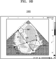
- the ultrasound apparatus 1000 may determine, based on the changed position of the first adjusting point 921, a point that is apart from the first adjusting point 921 by a pre-determined distance, along a direction of the straight line connecting the first adjusting point 921 and the cross point 925, as the second measuring point 913.
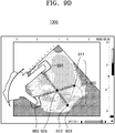
- the ultrasound apparatus 1000 may simultaneously move the first adjusting area 961, the second adjusting area 963, and the cross point 925, along a parallel direction.
- the measuring device image 910 corresponding to the scissors measuring device may include two measuring points 911 and 913 which indicate points in an ultrasound image that are to be measured. Also, the measuring device image 910 corresponding to the scissors measuring device may include two adjusting portions 991 and 993 which indicate adjusting areas. Also, the measuring device image 910 may display an image 953 indicating a circle having the two measuring points 911 and 913 as a diameter.
- the ultrasound apparatus 1000 may change the configured measuring area. Also, the ultrasound apparatus 1000 may calculate a diameter, a circumferential length, and an area of a circle based on the changed measuring area.
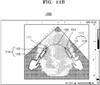
- the ultrasound apparatus 1000 may determine a segment connecting the trace point 1111.
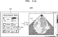
- the ultrasound apparatus 1000 may adjust a size of the pen measuring device image 1110. For example, when the ultrasound apparatus receives a long touch input with respect to the adjusting portion 1123 and a touch input dragging the adjusting portion 1123 in a lengthwise direction or the pen measuring device image 1110 or in the direction opposite thereto, the ultrasound apparatus 1000 may adjust the length of the pen measuring device image 1110. For example, when receiving the touch input extending the pen measuring device image 1110 in the lengthwise direction of the pen measuring device image 1110, the ultrasound apparatus 1000 may enlarge the size of the pen measuring device image 1110 by extending the pen measuring device image 1110 along the dragged area.
- the ultrasound apparatus 1000 may decrease the pen measuring device image 1110 along the dragged area.
- the ultrasound apparatus 1000 may change the pen measuring device image 1110 from 10cm to 5cm.
- the ultrasound apparatus 1000 may display a button image 1140 for storing information with respect to the configured line 1120.
- the information with respect to the configured line 1120 may include the position of the trace points 1111 forming the configured line 1120 and a measurement value with respect to the line 1120.
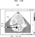
- the ultrasound apparatus 1000 may measure the angle of the two straight lines 1221 and 1223.
- the ultrasound apparatus 1000 may measure the angle of the two straight lines 1221 and 1223 based on a position of the three adjusting portions 1211, 1213, and 125.
- the ultrasound apparatus 1000 may measure the angle of the two straight lines 1221 and 1223 based on a position of the central point of the three adjusting portions 1211, 1213, and 1215.
- FIG. 12B is a view for describing a method of providing an angle measuring function via the ultrasound apparatus 1000, according to an embodiment.
- the ultrasound apparatus 1000 may measure the angle formed by the two straight lines 1321 and 1323. For example, the ultrasound apparatus 1000 may determine a cross point at which the two straight lines 1321 and 1323 meet each other when the two straight lines 1321 and 1323 extend, based on a position of the end points of the two straight lines 1321 and 1323. When the cross point is determined, the ultrasound apparatus 1000 may calculate the angle formed by the two straight lines 1321 and 1323 at the cross point.
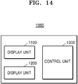
- the ultrasound apparatus 1000 may include a display unit 1100, a user input unit 1200, and a control unit 1300. However, not all of the illustrated components are essential. The ultrasound apparatus 1000 may be realized by more or less components that the illustrated components.
- the display unit 1100 may display on the ultrasound image a measuring device image including a plurality of measuring points indicating points in the ultrasound image that are to be measured, and adjusting portions for adjusting the plurality of measuring points.
- the measuring points may be disposed apart from the adjusting portions.
- the control unit 1300 may adjust a position of at least one of the plurality of measuring points based on the changed position of the adjusting portion and may obtain a measurement value based on a position of the plurality of measuring points including the at least one measuring point, the position of which is changed. Also, the control unit 1300 may adjust the position of the at least one of the plurality of measuring points by changing at least one of a position and a shape of the measuring device image.
- the display unit 1100 may display the obtained measurement value on the measuring device image.
- the display unit 1100 may display the measuring device image half-transparently so that an area of the ultrasound image, which overlaps the measuring device image, is not covered by the measuring device image.
- the display unit 1100 may display a button image for storing the measurement value, corresponding to the ultrasound image, on the ultrasound image.
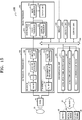
- a transmitter 110 supplies a driving signal to the probe 20.
- the transmitter 110 includes a pulse generator 112, a transmission delaying unit 114, and a pulser 116.
- the pulse generator 112 generates pulses for forming transmission ultrasound waves based on a predetermined pulse repetition frequency (PRF), and the transmission delaying unit 114 delays the pulses by delay times necessary for determining transmission directionality.
- the pulses which have been delayed correspond to a plurality of piezoelectric vibrators included in the probe 20, respectively.
- the pulser 116 applies a driving signal (or a driving pulse) to the probe 20 based on timing corresponding to each of the pulses which have been delayed.
- the memory 400 stores various data processed by the ultrasound apparatus 1000.
- the memory 400 may store medical data related to diagnosis of an object, such as ultrasound data and an ultrasound image that are input or output, and may also store algorithms or programs which are to be executed in the ultrasound apparatus 1000.
- All or some of the probe 20, the ultrasound transceiver 100, the image processor 200, the communication module 300, the memory 400, the user input unit 1200, and the controller 1300 may be implemented as software modules. However, embodiments of the present invention are not limited thereto, and some of the components stated above may be implemented as hardware modules. Furthermore, at least one selected from the ultrasound transceiver 100, the image processor 200, and the communication module 300 may be included in the controller 1300. However, embodiments of the present invention are not limited thereto.
Landscapes
- Engineering & Computer Science (AREA)
- Health & Medical Sciences (AREA)
- Life Sciences & Earth Sciences (AREA)
- Physics & Mathematics (AREA)
- Theoretical Computer Science (AREA)
- General Engineering & Computer Science (AREA)
- Medical Informatics (AREA)
- Public Health (AREA)
- General Health & Medical Sciences (AREA)
- Pathology (AREA)
- Biomedical Technology (AREA)
- Surgery (AREA)
- Heart & Thoracic Surgery (AREA)
- Molecular Biology (AREA)
- Radiology & Medical Imaging (AREA)
- Animal Behavior & Ethology (AREA)
- Nuclear Medicine, Radiotherapy & Molecular Imaging (AREA)
- Biophysics (AREA)
- Veterinary Medicine (AREA)
- Human Computer Interaction (AREA)
- General Physics & Mathematics (AREA)
- Computer Vision & Pattern Recognition (AREA)
- Physiology (AREA)
- Data Mining & Analysis (AREA)
- Databases & Information Systems (AREA)
- Epidemiology (AREA)
- Primary Health Care (AREA)
- Ultra Sonic Daignosis Equipment (AREA)
Abstract
Description
- This application claims the benefit of Korean Patent Application No.
10-2014-0174277, filed on December 5, 2014 - One or more exemplary embodiments relate to an ultrasound image processing method that obtains measurement information with respect to an object in an ultrasound image, based on an input of a user, and an ultrasound apparatus for executing the method.
- Ultrasound diagnosis apparatuses transmit ultrasound signals generated by transducers of a probe to an object and receive echo signals reflected from the object, thereby obtaining at least one image of an internal part of the object. In particular, ultrasound diagnosis apparatuses are used for medical purposes including observation of the interior of an object, detection of foreign substances, and diagnosis of damage to the object. Such ultrasound diagnosis apparatuses provide high stability, display images in real time, and are safe due to the lack of radioactive exposure, compared to X-ray apparatuses. Therefore, ultrasound imaging apparatuses are widely used together with other image diagnosis apparatuses.
- Meanwhile, sometimes a user has to measure a size, angle, area, or volume of an internal organ of a patient from an ultrasound image. Also, there is an occasion when a user needs to extract a characteristic of a graph or a figure indicated in an ultrasound image. In addition, a user may passively obtain a measurement value with respect to a measurement item that is to be measured, by using a measuring device, such as a caliper displayed in an ultrasound image.
- In order to increase the accuracy of a diagnosis, there is a need to provide a method and apparatus for increasing an accuracy of a measurement value by precisely and easily configuring a measurement item that a user aims to measure. In detail, a user interface for precisely configuring a measuring point in an ultrasound image by a simple input and for rapidly obtaining measurement information is required for a user to obtain measurement value.
- One or more exemplary embodiments include an ultrasound image processing method that measures an object indicated in an ultrasound image by using a measuring device which is determined according to an input of a user, and an ultrasound apparatus for executing the method.
- Additional aspects will be set forth in part in the description which follows and, in part, will be apparent from the description, or may be learned by practice of the presented embodiments.
- According to one or more exemplary embodiments, an ultrasound apparatus includes a display unit configured to display on an ultrasound image a measuring device image including a plurality of measuring points which indicate points on the ultrasound image that are to be measured, and an adjusting portion for adjusting the plurality of measuring points; a user input unit configured to receive a touch input for changing a position of the adjusting portion; and a controller configured to adjust a position of at least one of the plurality of measuring points based on the changed position of the adjusting portion, and to obtain a measurement value based on positions of the plurality of measuring points including the at least one measuring point, the position of which is adjusted, wherein the plurality of measuring points are disposed apart from the adjusting portion.
- The controller may adjust the position of the at least one of the plurality of measuring points by changing at least one of a position and a shape of the measuring device image, when the touch input for changing the position of the adjusting portion is received.
- The controller may adjust the position of the at least one of the plurality of measuring points by adjusting a size of the measuring device image, when the touch input for changing the position of the adjusting portion is received.
- The controller may adjust the position of the at least one of the plurality of measuring points by rotating the measuring device image, when the touch input for changing the position of the adjusting portion is received.
- The measuring device image may have a shape that two partial images cross each other based on a reference point. The controller may adjust the position of the at least one of the plurality of measuring points by rotating the two partial images based on the reference point, when the touch input for changing the position of the adjusting portion is received.
- The display unit may display the obtained measurement value on the measuring device image.
- The display unit may display the measuring device image in a half-transparent way so that an area of the ultrasound image, which overlaps the measuring device image, is not covered by the measuring device image.
- The touch input for changing the position of the adjusting portion may include a user input of touching and dragging the adjusting portion.
- The user input unit may receive a touch input of ending the user input of touching and dragging the adjusting portion. The display unit may display on the ultrasound image a button image for storing the obtained measurement value in correspondence with the ultrasound image, when the user input of touching and dragging the adjusting portion is ended.
- The input unit may receive a touch input of ending the user input of touching and dragging the adjusting portion. The display unit may delete the measuring device image and display on the ultrasound image a button image for re-adjusting the positions of the plurality of measuring points, when the user input of touching and dragging the adjusting portion is ended.
- According to one or more exemplary embodiments, a method of processing an ultrasound image includes: displaying on the ultrasound image a measuring device image including a plurality of measuring points which indicate points on the ultrasound image that are to be measured, and an adjusting portion for adjusting the plurality of measuring points; receiving a touch input for changing a position of the adjusting portion; and adjusting a position of at least one of the plurality of measuring points, based on the changed position of the adjusting portion, and obtaining a measurement value, based on positions of the plurality of measuring points including the at least one measuring point, the position of which is adjusted, wherein the plurality of measuring points are disposed apart from the adjusting portion.
- The adjusting of the position of the at least one of the plurality of measuring points may include adjusting the position of the at least one of the plurality of measuring points, by changing at least one of a position and a shape of the measuring device image, when the touch input for changing the position of the adjusting portion is received.
- The adjusting of the position of the at least one of the plurality of measuring points may include adjusting the position of the at least one of the plurality of measuring points by adjusting a size of the measuring device image, when the touch input for changing the position of the adjusting portion is received.
- The adjusting of the position of the at least one of the plurality of measuring points may include adjusting the position of the at least one of the plurality of measuring points by rotating the measuring device image, when the touch input for changing the position of the adjusting portion is received.
- The measuring device image may have a shape that two partial images cross each other based on a reference point. The adjusting of the position of the at least one of the plurality of measuring points may include adjusting the position of the at least one of the plurality of measuring points by rotating the two partial images based on the reference point, when the touch input for changing the position of the adjusting portion is received.
- The method may further include displaying the obtained measurement value on the measuring device image.
- The displaying of the measuring device image on the ultrasound image may include displaying the measuring device image in a half-transparent way so that an area of the ultrasound image, which overlaps the measuring device image, is not covered by the measuring device image.
- The touch input for changing the position of the adjusting portion may include a user input of touching and dragging the adjusting portion.
- The method may further include receiving a touch input of ending the user input of touching and dragging the adjusting portion, and displaying on the ultrasound image a button image for storing the measurement value in correspondence with the ultrasound image, when the user input of touching and dragging the adjusting portion is ended.
- The method may further include receiving a touch input of ending the user input of touching and dragging the adjusting portion, and deleting the measuring device image and displaying on the ultrasound image a button image for re-adjusting the positions of the plurality of measuring points, when the user input of touching and dragging the adjusting portion is ended.
- Embodiments of the invention now will be described more fully hereinafter with reference to the accompanying drawings, in which reference numerals denote structural elements.
-
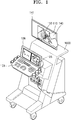
FIG. 1 is a view of an ultrasound apparatus according to an embodiment; -
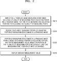
FIG. 2 is a flowchart of a method of obtaining a measurement value via an ultrasound apparatus, according to an embodiment; -
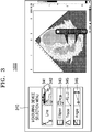
FIG. 3 is a view for describing a method of providing a measuring device selection menu via an ultrasound apparatus, according to an embodiment; -
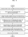
FIG. 4 is a flowchart of a method of providing a measuring device via an ultrasound apparatus, according to an embodiment; -
FIG. 5A is a view for describing a method of providing a distance measuring function via a vernier caliper measuring device, via an ultrasound apparatus, according to an embodiment; -
FIG. 5B is a view for describing a method of displaying a vernier caliper measuring device image corresponding to a vernier caliper measuring device, via an ultrasound apparatus, according to an embodiment; -
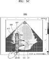
FIG. 5C is a view for describing a method of indicating a measuring point by changing a position or a shape of a vernier caliper measuring device image, according to an input of a user, via an ultrasound apparatus, according to an embodiment; -
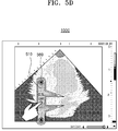
FIG. 5D is a view for describing a method of configuring a measuring point by changing a position of a vernier caliper measuring device image, according to an input of a user, via an ultrasound apparatus, according to another embodiment. -
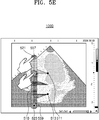
FIG. 5E is a view for describing a method of indicating a measuring point by changing a position or a shape of a vernier caliper measuring device image, according to an input of a user, via an ultrasound apparatus, according to another embodiment; -
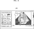
FIG. 6 is a view for describing a method of storing a calculated measurement value via an ultrasound apparatus, according to an embodiment; -
FIG. 7A is a view for describing a method of providing a distance measuring function via a pincette measuring device, via an ultrasound apparatus, according to an embodiment; -
FIG. 7B is a view for describing a method of providing a pincette measuring device, via an ultrasound apparatus, according to another embodiment; -
FIG. 8 is a flowchart of a method of providing a measuring function via a scissors measuring device, via an ultrasound apparatus, according to an embodiment; -
FIG. 9A is a view for describing a method of providing a measuring function via a scissors measuring device, via an ultrasound apparatus, according to an embodiment; -
FIG. 9B is a view for describing a method of obtaining measurement information with respect to a circle via a scissors measuring device, via an ultrasound apparatus, according to an embodiment; -
FIG. 9C is a view for describing a method of displaying a measuring device image corresponding to a scissors measuring device, via an ultrasound apparatus, according to an embodiment; -
FIG. 9D is a view for describing a method of indicating a measuring point by changing a position or a shape of a measuring device image, according to an input of a user, via an ultrasound apparatus, according to an embodiment; -
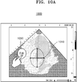
FIG. 10A is a view for describing a method of providing a measuring function in a direct change mode, via an ultrasound apparatus, according to another embodiment; -
FIG. 10B is a view for describing a method of changing a configured measuring area in a direct change mode, via an ultrasound apparatus, according to an embodiment; -
FIG. 11A is a view for describing a method of providing a measuring function via a pen measuring device, via an ultrasound apparatus, according to an embodiment; -
FIG. 11B is a view for describing a method of providing a trace function via a pen measuring device image, via an ultrasound apparatus, according to another embodiment; -
FIG. 11C is a view for describing a method of providing a trace function, via an ultrasound apparatus, according to another embodiment; -
FIG. 12A is a view for describing a method of providing an angle measuring function, via an ultrasound apparatus, according to an embodiment; -
FIG. 12B is a view for describing a method of providing an angle measuring function, via an ultrasound apparatus, according to an embodiment; -
FIG. 13 is a view for describing a method of providing an angle measuring function, via an ultrasound apparatus, according to another embodiment; -
FIG. 14 is a block diagram of an ultrasound apparatus according to an embodiment; and -
FIG. 15 is a block diagram of an ultrasound apparatus according to another embodiment. - Hereinafter, the terms used in the specification will be briefly defined, and the embodiments will be described in detail.
- The terms used in this specification are those general terms currently widely used in the art in consideration of functions regarding the present invention, but the terms may vary according to the intention of those of ordinary skill in the art, precedents, or new technology in the art. Also, some terms may be arbitrarily selected by the applicant, and in this case, the meaning of the selected terms will be described in detail in the detailed description of the present specification. Thus, the terms used in the specification should be understood not as simple names but based on the meaning of the terms and the overall description of the invention.
- When a part "includes" or "comprises" an element, unless there is a particular description contrary thereto, the part can further include other elements, not excluding the other elements. In addition, terms such as "... unit", "... module", or the like refer to units that perform at least one function or operation, and the units may be implemented as hardware or software or as a combination of hardware and software.
- Throughout the specification, an "ultrasound image" refers to an image of an object, which is obtained using ultrasound waves. The object may refer to a part of a human body. For example, the object may include organs, such as the liver, the heart, the brain, a breast, and the abdomen, or a fetus.
- In the present specification, the term "user" may refer to a medical professional, such as a doctor, a nurse, a medical laboratory technologist, a medical imaging technologist, or a sonographer, but the user is not limited thereto.
- Throughout the specification, the term "measuring device" may refer to a measuring application that receives a user input for configuring a position of a measuring point and provides measurement information with respect to an object in a ultrasound image based on the configured position of the measuring point, by using an image indicating a measuring point in an ultrasound image as a medium.
- The term "measuring device image" refers to a measuring point, and may refer to an image medium of a graphic user interface for receiving the user input configuring the position of the measuring point.
- For example, when the ultrasound apparatus receives a user input selecting a measuring device for measuring a distance, the ultrasound apparatus may display on the ultrasound image the measuring device image indicating two measuring points in the ultrasound image. Also, the ultrasound apparatus may receive a user input configuring the position of the measuring point via the measuring device image. When receiving the user input configuring the position of the measuring point, the ultrasound apparatus may measure a distance based on the configured position of the measuring point.
- Reference will now be made in detail to embodiments, examples of which are illustrated in the accompanying drawings. In this regard, the present embodiments may have different forms and should not be construed as being limited to the descriptions set forth herein. Also, parts in the drawings unrelated to the detailed description are omitted to ensure clarity of the inventive concept. Like reference numerals refer to like elements throughout.
-
FIG. 1 is a diagram illustrating anultrasound apparatus 1000 according to exemplary embodiments. Theultrasound apparatus 1000 may include adisplay unit 141, aninput unit 103, and a controller (not shown). Theinput unit 103 may further include a predetermined screen, or a display panel or atouch screen 106 for visually providing information to a user, in addition to an input device for a user to input data, commands or requests to theultrasound apparatus 1000. Also, thedisplay unit 141 may operate as a touch screen receiving a user's touch input. - Referring to
FIG. 1 , thedisplay unit 141 of theultrasound apparatus 1000 may display anultrasound image 130 on thetouch screen 106. Also, theultrasound apparatus 1000 may display on the ultrasound image 130 ameasuring device image 110 for measuring an object included in theultrasound image 130. - The
ultrasound apparatus 1000 may determine one from among a plurality of measuring devices, based on a user input that is input through theinput unit 103. For example, theultrasound apparatus 1000 may determine one from among the plurality of measuring devices, when receiving the user input selecting the measuring device. - When the
ultrasound apparatus 1000 determines one from among the plurality of measuring devices, theultrasound apparatus 1000 may display ameasuring device image 110 corresponding to the measuring device, on theultrasound image 130. For example, when theultrasound apparatus 1000 receives a user input selecting anicon 105 indicating a length measuring device for measuring a length of a specific part of an organ or a specific bone, theultrasound apparatus 1000 may display a lengthmeasuring device image 110 corresponding to the length measuring device, on theultrasound image 130. - The measuring
device image 110 may include a measuring point which indicates a point on the ultrasound image that is to be measured. Also, the measuringdevice image 110 may include an adjusting portion for receiving a user input adjusting a position of the measuring point. In this case, the measuring point may be disposed apart from the adjusting portion. Accordingly, the user may precisely configure the measuring portion, without covering with a finger the measuring portion on the ultrasound image. - Also, the
ultrasound apparatus 1000 may receive a touch input changing a position of the adjusting portion. - Also, the
ultrasound apparatus 1000 may adjust a position of at least one of the plurality of measuring points, based on the changed position of the adjusting portion, and may obtain a measurement value, based on a position of the plurality of measuring points including the at least one measuring point, the position of which is adjusted. - Also, the
ultrasound apparatus 1000 may display the obtained measurement value. - When the
ultrasound apparatus 1000 receives a touch input with respect to the adjusting portion, theultrasound apparatus 1000 may change a position of the adjusting portion and the measuring point, in the ultrasound image, by changing at least one of a position and a shape of the measuringdevice image 110. - For example, when receiving the touch input with respect to the adjusting portion, the
ultrasound apparatus 1000 may determine the position of the measuring point based on the position of the adjusting portion. Also, when the position of the measuring point is determined, theultrasound apparatus 1000 may display the measuring point by shifting the measuring point in the measuring device image. In this case, theultrasound apparatus 1000 may shift the measuring point by changing at least one of the shape and the position of the measuringdevice image 110. - Also, when the position of the measuring point is determined, the
ultrasound apparatus 1000 may calculate a measurement value with respect to a measurement item corresponding to a measuring device that is selected based on the determined position of the measuring point. The measurement item may include information associated with a length, an angle, an area, and a volume. - Shapes of a measuring device image for measuring a distance may be a physical vernier caliper or a physical pincette. Also, shapes of a measuring device image for measuring an area may be the physical scissors. Also, shapes of a measuring device image for measuring an outline may be a physical pen. Accordingly, the user may instinctively recognize an interface method with respect to the measuring device.
-
FIG. 2 is a flowchart of a method of obtaining a measurement value via theultrasound apparatus 1000, according to an embodiment. - The
ultrasound apparatus 1000 may display a measuring device image including a plurality of measuring points, which indicate points on an ultrasound image that are to be measured, and an adjusting portion for adjusting the plurality of measuring points, on the ultrasound image, in operation S210. - The
ultrasound apparatus 1000 may receive a user input selecting one from among a plurality of measuring devices. - The measuring devices may refer to a measuring application which receives a user input configuring a position of the measuring point, and provides a measurement value with respect to an object in an ultrasound image based on the position of the measuring point, by using an image indicating a point on an ultrasound image that is to be measured as a medium.
- The ultrasound image may be at least one selected from a B (brightness) mode image indicating a magnitude of an ultrasound echo signal reflected from an object as a brightness, a C (color) mode image indicating a speed of a moving object as a color by using a Doppler effect, a D (Doppler) mode image indicating an image of the moving object as a spectrum by using the Doppler effect, an M (motion) mode image indicating a motion of an object according to time in a predetermined position, and an E (elastic) mode image indicating a difference in a reaction between when compression is and is not applied to an object, as an image. However, the ultrasound image is not limited thereto. Also, the ultrasound image may be a two-dimensional image, a three-dimensional image, or a four-dimensional image. The
ultrasound apparatus 1000 may obtain the ultrasound image by photographing an object. Also, theultrasound apparatus 1000 may receive the ultrasound image from an external device. - The
ultrasound apparatus 1000 may determine one from among a plurality of measuring devices, based on a user input selecting one from among the plurality of measuring devices for measuring the object in the ultrasound image. For example, theultrasound apparatus 1000 may provide a measuring device selection menu for selecting one from among the plurality of measuring devices. Theultrasound apparatus 1000 may display the measuring device selection menu together with the ultrasound image on one screen. Also, theultrasound apparatus 1000 may display the measuring device selection menu on a separate screen that is different from a touch screen on which the ultrasound image is displayed. - Also, the
ultrasound apparatus 1000 may determine one from among the plurality of measuring devices, based on a user input selecting one from among a plurality of measurement items. The measurement item may include a length, a width, or an angle, but it is not limited thereto. When theultrasound apparatus 1000 receives the user input selecting one measurement item, theultrasound apparatus 1000 may determine a measuring device that is predetermined in correspondence to the selected measurement item. - Also, the
ultrasound apparatus 1000 may determine one from among the plurality of measuring devices, based on a pattern of a user input. For example, when theultrasound apparatus 1000 receives a user input touching two points on a touch screen and dragging the two points in opposite directions, theultrasound apparatus 1000 may determine an oval measuring device as the measuring device. Also, when theultrasound apparatus 1000 receives a user input touching two points on the touch screen and rotating one point, theultrasound apparatus 1000 may determine a degree measuring device as the measuring device. - The
ultrasound apparatus 1000 may display on the ultrasound image a measuring device image corresponding to the selected measuring device. - The measuring device image refers to a point that is to be measured in the ultrasound image, and may refer to an image medium of a graphic user interface for receiving a user input configuring a position of the measuring point. The measuring device image may be pre-stored in correspondence to the measuring device.
- When the
ultrasound apparatus 1000 determines one from among the plurality of measuring devices, theultrasound apparatus 1000 may display a measuring device image corresponding to the determined measuring device, on the ultrasound image. - For example, when a vernier caliper measuring device is determined, the
ultrasound apparatus 1000 may display a vernier caliper measuring device image on the ultrasound image. Also, when a pincette measuring device is determined, theultrasound apparatus 1000 may display a pincette measuring device image on the ultrasound image. Also, when a scissors measuring device is determined, theultrasound apparatus 1000 may display a scissors measuring device image on the ultrasound image. - The measuring device image may include a plurality of measuring points which indicate points on the ultrasound image that are to be measured. The points on the ultrasound image that are to be measured may be points in the ultrasound image, which is a reference for measurement. The measuring points on the ultrasound image may be configured by the user via the measuring device image. A position of the plurality of measuring points in the measuring device image may be pre-determined in correspondence to the measuring device image. For example, the plurality of measuring points in the measuring device image having a shape of the scissors, the plurality of measuring points may be both edges of the scissors.
- Also, the measuring device image may include an adjusting portion for adjusting the position of the plurality of measuring points. Also, a position of the adjusting portion in the measuring device image may be pre-determined in correspondence to the measuring device image. For example, the adjusting portion in the measuring device image having the shape of the scissors may be a handle portion of the scissors.
- The adjusting portion may be disposed not to overlap the plurality of measuring points in the measuring device image. For example, the adjusting portion may be apart from the plurality of measuring points in the measuring device image by a predetermined distance.
- Also, the
ultrasound apparatus 1000 may display the measuring device image such that the adjusting portion may be distinguished from other portions of the measuring device image. For example, theultrasound apparatus 1000 may display the adjusting portion in a different color from other portions of the measuring device image. - The
ultrasound apparatus 1000 may display the measuring device image half-transparently so that a portion of the ultrasound image, which overlaps the measuring device image, is not covered by the measuring device image. - The
ultrasound apparatus 1000 may receive a touch input changing a position of the adjusting portion of the measuring device image on the ultrasound image, in operation S220. - The
ultrasound apparatus 1000 may receive a touch and drag input with respect to the adjusting portion in the measuring device image. For example, theultrasound apparatus 1000 may receive the input of touching the adjusting portion via a finger or an electronic pen, and dragging the finger or the electronic pen to another position in a screen, while maintaining the state of touching. When theultrasound apparatus 1000 receives the touch and drag input, theultrasound apparatus 1000 may move the adjusting portion along the drag. - In this case, the
ultrasound apparatus 1000 may move the adjusting portion in the measuring device image by changing at least one of a position and a shape of the ultrasound image. - In operation S230, the
ultrasound apparatus 1000 may adjust a position of at least one of the plurality of measuring points based on the changed position of the adjusting portion, and may obtain a measurement value based on a position of the plurality of measuring points including the at least one measuring point, the position of which is adjusted. - When the position of the adjusting portion is changed in the ultrasound image, the
ultrasound apparatus 1000 may determine the position of the measuring point based on the position of the adjusting portion. - For example, the
ultrasound apparatus 1000 may determine a point that is apart from a central point of the adjusting portion, by a pre-determined distance, as the measuring point. Also, theultrasound apparatus 1000 may determine a point that is apart from a pre-determined adjusting point in the adjusting portion, by a predetermined distance, along a direction of a straight line connecting the adjusting point and at least one reference point in the ultrasound image, as the measuring point. In this case, theultrasound apparatus 1000 may adjust a position of at least one of the plurality of measuring points by changing at least one of a position and a shape of the measuring device image. - For example, the
ultrasound apparatus 1000 may adjust the position of the at least one of the plurality of measuring points by adjusting a length of the measuring device image. Also, for example, theultrasound apparatus 1000 may adjust the position of the at least one of the plurality of measuring points by rotating the measuring device image. Also, when the measuring device image is formed of two partial images crossing each other, based on a reference point, theultrasound apparatus 1000 may adjust the position of the at least one of the plurality of measuring points by rotating the two partial images based on the reference point. - The
ultrasound apparatus 1000 may obtain a measurement value with respect to a measurement item corresponding to a selected measuring device, based on the position of the plurality of measuring points. - When the position of the at least one of the plurality of measuring points is adjusted, the
ultrasound apparatus 1000 may obtain the measurement value with respect to the measurement item corresponding to the selected measuring device, based on the position of the plurality of measuring points in the ultrasound image. - For example, the
ultrasound apparatus 1000 may measure a distance between two measuring points on the ultrasound image, based on a position of the two measuring points on the measuring device image. Theultrasound apparatus 1000 may generate a circle having a straight line connecting the two measuring points as a diameter, based on the position of the measuring points, and may calculate at least one of the diameter, a circumferential length, and an area of the generated circle. - In this case, the
ultrasound apparatus 1000 may convert a scale on the ultrasound image into a scale on a real object, in order to calculate a length, an area, and a volume. - Also, the
ultrasound apparatus 1000 may configure an interest area on the ultrasound image based on the position of the plurality of measuring points and obtain a measurement value with respect to the configured interest area. For example, theultrasound apparatus 1000 may configure a gate on the ultrasound image based on a position of two measuring points and measure a blood flow speed of an area indicated by the gate. - The
ultrasound apparatus 1000 may display the obtained measurement value in operation S240. - The
ultrasound apparatus 1000 may display the obtained measurement value on the measurement device image. - Also, the
ultrasound apparatus 1000 may receive a touch input ending a touch and drag with respect to the adjusting portion. When receiving the touch input ending the touch and drag with respect to the adjusting portion, theultrasound apparatus 1000 may display a button image for storing a measurement value, corresponding to the ultrasound image, on the ultrasound image. - Also, when receiving the touch input ending the touch and drag, the
ultrasound apparatus 1000 may delete the measuring device image on the touch screen and may display a button image for re-adjusting the position of the plurality of measuring points, on the ultrasound image. -
FIG. 3 is a view for describing a method of providing a measuringdevice selection menu 340 via theultrasound apparatus 1000, according to an embodiment. - Referring to
FIG. 3 , theultrasound apparatus 1000 may display the measuringdevice selection menu 340. - The measuring
device selection menu 340 may includeicons 341 through 346 for selecting a measuring device. - Also, the measuring
device selection menu 340 may include information indicating shapes of an area measured by the measuring device. For example, theultrasound apparatus 1000 may display a word 'line' indicating a distance, and an image indicating the distance, together with an icon for selecting a length measuring device. - Also, the measuring
device selection menu 340 may include information indicating a measurement item measured by the measuring device. For example, theultrasound apparatus 1000 may display a word 'angle' indicating an angle measured by the measuring device, and an angle image, together with an icon indicating an angle measuring device. - Also, when the
ultrasound apparatus 1000 receives a user input selecting one from among the plurality of measuring devices, theultrasound apparatus 1000 may display a measuring device image corresponding to the selected measuring device, on the ultrasound image. For example, when receiving a user input selecting theicon 341 for selecting a vernier caliper measuring device, theultrasound apparatus 1000 may display a vernier caliper measuring device image corresponding to the vernier caliper measuring device, on the ultrasound image. -
FIG. 3 illustrates a case in which the measuringdevice selection menu 340 includes the vernier calipermeasuring device icon 341 corresponding to the vernier caliper measuring device for measuring a distance between a plurality of measuring points, a pincettemeasuring device icon 342 corresponding to a pincette measuring device, a scissors measuringdevice icon 343 corresponding to a scissors measuring device for measuring a measurement item with respect to an oval, a penmeasuring device icon 345 corresponding to a pen measuring device for measuring an item with respect to a trace generated based on a user's touch trace, and an anglemeasuring device icon 346 corresponding to an angle measuring device. However, the measuring device may have other various shapes, and the measuringdevice selection menu 340 may include other measuring device icons corresponding to the measuring devices having various shapes. -
FIG. 4 is a flowchart of a method of providing a measuring device via theultrasound apparatus 1000, according to an embodiment. - The
ultrasound apparatus 1000 may receive an input of selecting a vernier caliper measuring device, in operation S410. - The
ultrasound apparatus 1000 may display a vernier caliper measuring device image, on an ultrasound image, in operation S420. - The
ultrasound apparatus 1000 may display the vernier caliper measuring device image corresponding to the vernier caliper measuring device, on the ultrasound image. - The vernier caliper measuring device image may have a physical shape of a vernier caliper.
- The vernier caliper measuring device image may include two measuring points which indicate positions of the two points in the ultrasound image that are to be measured. Also, the vernier caliper measuring device image may include an adjusting portion for adjusting the position of the measuring points.
- The
ultrasound apparatus 1000 may receive a touch input changing a position of the adjusting portion in the vernier caliper measuring device image, on the ultrasound image, in operation S430. - When the
ultrasound apparatus 1000 receives a touch and drag input with respect to the adjusting portion, theultrasound apparatus 1000 may move the adjusting portion along the dragged area. In this case, theultrasound apparatus 1000 may move the adjusting portion by changing at least one of a shape and a position of the adjusting portion. - The
ultrasound apparatus 1000 may determine a position of two measuring points that are apart from the adjusting portion by a pre-determined distance, based on the changed position of the adjusting portion, in operation S440. - When the at least one of the shape and the position of the adjusting portion is changed, the
ultrasound apparatus 1000 may determine a position of a plurality of measuring points, based on the position of the adjusting portion. - For example, the
ultrasound apparatus 1000 may determine a position of a measuring point based on a position of an adjusting point. The adjusting point may be a point in the measuring device image, which is becomes a reference point for determining the position of the measuring point. The position of the adjusting point may be a fixed point in the adjusting portion. For example, the position of the adjusting point may be a central point of the adjusting portion. Theultrasound apparatus 1000 may determine the position of the adjusting point based on the position of the adjusting portion. - When the
ultrasound apparatus 1000 determines the position of the adjusting point, theultrasound apparatus 1000 may determine a position of a point that is apart from a first adjusting point by a pre-determined distance and a position of a point that is apart from a second adjusting point by a pre-determined distance, the points apart from the first and second adjusting points being from among a plurality of points on a straight line connecting the first and second adjusting points, and then may determine points that are respectively apart from the determined positions by a predetermined distance, along a direction perpendicular to the straight line, as the measuring point. - The
ultrasound apparatus 1000 may adjust a position of at least one of two measuring points in the vernier caliper measuring device image, in operation S450. - The
ultrasound apparatus 1000 may adjust the position of the at least one of the two measuring points, by changing at least one of a position and a shape of the vernier caliper measuring device image. - For example, the
ultrasound apparatus 1000 may adjust the position of the at least one of the two measuring points, by rotating the vernier caliper measuring device image. Also, theultrasound apparatus 1000 may adjust the position of the at least one of the two measuring points, by lengthening the vernier caliper measuring device image. - The
ultrasound apparatus 1000 may calculate a distance between the two measuring points based on the determined position of the two measuring points, in operation S460. - The
ultrasound apparatus 1000 may display the calculated distance, in operation S470. -
FIG. 5A is a view for describing a method of providing a distance measuring function via a vernier caliper measuring device, via theultrasound apparatus 1000, according to an embodiment. - Referring to
FIG. 5A , when the vernier caliper measuring device is selected, theultrasound apparatus 1000 may determine a measuring point and an adjusting portion on an ultrasound image. - For example, when receiving a user input selecting the
icon 341 indicating the vernier caliper measuring device in the measuringdevice selection menu 340 illustrated inFIG. 3 , theultrasound apparatus 1000 may obtain a position of two measuringpoints portion 530 on the ultrasound image. The adjustingportion 530 may include afirst adjusting portion 531 and asecond adjusting portion 533. A user may configure the measuring points 511 and 513 at a part that is to be measured in an object in the ultrasound image. For example, when the object is a fetus, and the measuring part is a nuchal translucency (NT) of the fetus, the user may locate the measuring points 511 and 531 at two end points of the NT. In this case, the user may move the first and second adjustingportions - In detail, the measuring
points portions points portion 530 may be pre-determined in correspondence to the vernier caliper measuring device. - The vernier caliper measuring device may be a device for calculating a distance between the two measuring
points ultrasound apparatus 1000 may calculate the distance between the two measuringpoints points - When the
ultrasound apparatus 1000 receives a touch and drag input with respect to the adjustingportion 530, theultrasound apparatus 1000 may move the adjustingportion 530 along the dragged area. In this case, theultrasound apparatus 1000 move the adjustingportion 530 by changing at least one of a shape and a position of the adjustingportion 530. - The
first adjusting portion 531 may be configured to move above and below. Also, thesecond adjusting portion 533 may be configured to move above and below or to rotate based on afirst adjusting point 521. Also, both of the adjustingportions - Other areas of the adjusting
portion 530, except for thefirst adjusting portion 531 and thesecond adjusting portion 533, may be areas for the two measuringpoints portion 530 to simultaneously move in the parallel direction. - When the adjusting
portion 530 moves, theultrasound apparatus 1000 may determine a position of the measuring points 511 and 513 based on the position of the adjustingportion 530. For example, theultrasound apparatus 1000 may determine a position of adjustingpoints first adjusting portion 531 and thesecond adjusting portion 533. The adjusting points 521 and 523 may be a point in the ultrasound image, which is becomes a reference point for determining the position of the measuring points 511 and 513. The position of the adjusting points 521 and 523 may be a central point of thefirst adjusting portion 531 and thesecond adjusting portion 533. - Also, when the position of the
first adjusting portion 531 and thesecond adjusting portion 533 changes in the ultrasound image, theultrasound apparatus 1000 may determine a position of apoint 526 that is apart from thefirst adjusting point 521 by a pre-determined distance and a position of apoint 527 that is apart from thesecond adjusting point 523 by a pre-determined distance, thepoints points determined positions points portions - As illustrated in
FIG. 5A , since the adjustingportion 530 is spaced apart from the measuringpoints points portion 530 on a touch screen. - Also, when the position of the
first adjusting portion 531 and thesecond adjusting portion 533 is changed in the ultrasound image, theultrasound apparatus 1000 may store the changed position of thefirst adjusting portion 531 and thesecond adjusting portion 533 and the calculated position of the measuring points 511 and 513. -
FIG. 5B is a view for describing a method of displaying a vernier calipermeasuring device image 510 corresponding to a vernier caliper measuring device via theultrasound apparatus 1000, according to an embodiment. - Referring to
FIG. 5B , when the vernier caliper measuring device is selected, theultrasound apparatus 1000 may display the vernier calipermeasuring device image 510 corresponding to the vernier caliper measuring device. - The vernier caliper
measuring device image 510 may include two measuringpoints measuring device image 510 may include an adjustingportion 555 indicating an adjusting area. The adjustingportion 555 may include afirst adjusting portion 557 indicating a position of a first adjusting area and asecond adjusting portion 559 indicating a position of a second adjusting area. - The measuring points are located apart from the adjusting
portion 555 by a pre-determined distance, and thus, the adjustingportion 555 indicating the adjusting area may be displayed at a location that is apart from the measuring points by the predetermined distance. - The vernier caliper
measuring device image 510 may have a physical shape of a vernier caliper. For example, the adjustingportion 555 may correspond to an area of a bar shape. Also, the two measuringpoints portion 555 by a pre-determined distance. - Also, when the adjusting
portion 555 and the measuring points 511 and 513 are changed by a user's touch input, theultrasound apparatus 1000 may change at least one of a position and a shape of the vernier calipermeasuring device image 510 such that the adjustingportion 555 in the vernier calipermeasuring device image 510 is located on the adjusting area and the two measuringpoints - Accordingly, a user may recognize a measuring point configured on the ultrasound image and a position of the adjusting
area 530, from the vernier calipermeasuring device image 510 displayed on the ultrasound image. Also, theultrasound apparatus 1000 may receive a touch input with respect to the adjustingarea 530, by receiving a touch input moving the adjustingportion 555 in the vernier calipermeasuring device image 510. For example, the position of the first adjusting area may be moved along an area touched by the user. Theultrasound apparatus 1000 may receive a user's touch input moving the position of thefirst adjusting portion 557 by displaying thefirst adjusting portion 557 on the moved first adjusting area. -
FIG. 5C is a view for describing a method of indicating a measuring point by changing a position or a shape of the vernier calipermeasuring device image 510, according to a user input, via theultrasound apparatus 1000, according to an embodiment. - Referring to
FIG. 5C , theultrasound apparatus 1000 may receive a touch input changing the position of thesecond adjusting portion 559. For example, theultrasound apparatus 1000 may receive a touch input touching and dragging thesecond adjusting portion 559. When receiving the touch input touching and dragging thesecond adjusting portion 559, theultrasound apparatus 1000 may adjust a position of two measuringpoints measuring device image 510. - For example, the
ultrasound apparatus 1000 may receive the touch input rotating thesecond adjusting portion 559 based on thefirst adjusting point 521 that is the center of thefirst adjusting portion 557. When receiving the touch input rotating thesecond adjusting portion 559, theultrasound apparatus 1000 may determine a position of thesecond adjusting point 523 based on the position of thesecond adjusting portion 559. When the position of thesecond adjusting point 523 is determined, theultrasound apparatus 1000 may determine the position of the two measuringpoints first adjusting point 521 and the determined position of thesecond adjusting point 523. - Also, when receiving the touch input rotating the
second adjusting portion 559, theultrasound apparatus 1000 may rotate the vernier calipermeasuring device image 510. When the vernier calipermeasuring device image 510 is rotated, a point in the ultrasound image that is indicated by the measuringpoints measuring device image 510 may be a point that is to be measured. - Also, for example, the
ultrasound apparatus 1000 may receive a touch input reducing or increasing a length of the vernier calipermeasuring device image 510. For example, theultrasound apparatus 1000 may receive a touch input moving thesecond adjusting portion 559 in a lengthwise direction of the vernier calipermeasuring device image 510. When receiving the touch input moving thesecond adjusting portion 559 in the lengthwise direction of the vernier calipermeasuring device image 510, theultrasound apparatus 1000 may determine the position of thesecond adjusting point 523, based on the position of thesecond adjusting portion 559. When the position of thesecond adjusting point 523 is determined, theultrasound apparatus 1000 may determine the position of thesecond measuring point 513, based on thefirst adjusting point 521 and the determined position of thesecond adjusting point 523. Also, a distance between thefirst measuring point 511 and thesecond measuring point 513 may be calculated based on thefirst measuring point 511 and the determined position of thesecond measuring point 513. - Also, when receiving the touch input moving the
second adjusting portion 559 in the lengthwise direction of the vernier calipermeasuring device image 510, the length of the vernier calipermeasuring device image 510 may be increased or decreased. When the length of the vernier calipermeasuring device image 510 is increased or decreased, the point in the ultrasound image that is indicated by the measuringpoints measuring device image 510 may be a point that is to be measured. -
FIG. 5D is a view for describing a method of configuring a measuring point by changing a position of the vernier calipermeasuring device image 510, according to a user input, via theultrasound apparatus 1000, according to another embodiment. - Referring to
FIG. 5D , theultrasound apparatus 1000 may receive a touch input moving the entire vernier calipermeasuring device image 510. - For example, the
ultrasound apparatus 1000 may receive a user input touching other areas of the entire adjusting portion except for the first adjusting portion and the second adjusting portion. When theultrasound apparatus 1000 receives the user input touching other areas of the entire adjusting portion except for the first adjusting portion and the second adjusting portion, theultrasound apparatus 1000 may display animage 560 indicting that the entire vernier calipermeasuring device image 510 is selected, on the vernier calipermeasuring device image 510. - Also, when the
ultrasound apparatus 1000 receives a touch input moving the entire vernier calipermeasuring device image 510, theultrasound apparatus 1000 may move the entire vernier calipermeasuring device image 510. When the entire vernier calipermeasuring device image 510 is moved, a point in the ultrasound image that is indicated by a measuring point in the vernier calipermeasuring device image 510 may be a point that is to be measured. - Also, although it is not illustrated in
FIG. 5D , the left and the right of the vernier calipermeasuring device image 510 may be changed. For example, when theultrasound apparatus 1000 receives a user input double-clicking the vernier calipermeasuring device image 510, theultrasound apparatus 1000 may display the vernier calipermeasuring device image 510 changing the left and the right. -
FIG. 5E is a view for describing a method of indicating a measuring point by changing a position or a shape of the vernier calipermeasuring device image 510, according to a user input, via theultrasound apparatus 1000, according to another embodiment. - Referring to
FIG. 5E , theultrasound apparatus 1000 may receive a touch input changing a position of thefirst adjusting portion 557. When receiving the input changing the position of thefirst adjusting portion 557, theultrasound apparatus 1000 may adjust a position of thefirst measuring point 511 in an ultrasound image by changing at least one of the position and the shape of the vernier calipermeasuring device image 510. - Also, the
ultrasound apparatus 1000 may receive a touch input increasing or decreasing a length of the vernier calipermeasuring device image 510. For example, theultrasound apparatus 1000 may receive a touch input moving thefirst adjusting portion 557 in a lengthwise direction of the vernier calipermeasuring device image 510. When receiving the touch input moving thefirst adjusting portion 557 in the lengthwise direction of the vernier calipermeasuring device image 510, theultrasound apparatus 1000 may determine the position of thefirst adjusting point 521, based on the position of thefirst adjusting portion 557. When the position of thefirst adjusting point 521 is determined, theultrasound apparatus 1000 may determine the position of thefirst measuring point 511, based on the changed first adjustingpoint 521 and thesecond adjusting point 523. Also, a distance between thefirst measuring point 511 and thesecond measuring point 513 may be calculated based on the determined position of thefirst measuring point 511 and thesecond measuring point 513. - Also, when receiving the touch input moving the
first adjusting portion 557 in the lengthwise direction of the vernier calipermeasuring device image 510, theultrasound apparatus 1000 may change the position of thefirst adjusting portion 557 by increasing or decreasing the length of the vernier calipermeasuring device image 510. When the length of the vernier calipermeasuring device image 510 is increased or decreased, the point in the ultrasound image that is indicated by the measuringpoints measuring device image 510 may be a point that is to be measured. -
FIG. 6 is a view for describing a method of storing a calculated measurement value via theultrasound apparatus 1000, according to an embodiment. - Referring to
FIG. 6 , theultrasound apparatus 1000 may display a button image for storing the calculated measurement value, on an ultrasound image. - For example, when the
ultrasound apparatus 1000 receives a user input ending a touch and drag input with respect to an adjusting portion in a measuring device image, theultrasound apparatus 1000 may display the button image for storing the calculated measurement value. - When receiving the input touching the button image for storing the calculated measurement value, the
ultrasound apparatus 1000 may store the calculated measurement value in correspondence to identification information of the ultrasound image. - Also, when the user selects a measuring part and a measuring
item 620 before selecting a measuring device, theultrasound apparatus 1000 may display or store the calculated measurement value as a measurement value corresponding to the pre-selected measurement part and measurement item, when receiving the user input touching the icon for storing the measurement value. - Also, the
ultrasound apparatus 1000 may store not only the measurement value but also a position of a measuring point and an adjusting area. -
FIG. 7A is a view for describing a method of providing a distance measuring function via a pincette measuring device, via theultrasound apparatus 1000, according to an embodiment. - Referring to
FIG. 7A , theultrasound apparatus 1000 may display a pincettemeasuring device image 710 on an ultrasound image. - When the
ultrasound apparatus 1000 receives a user input selecting the pincettemeasuring device icon 342 in the measuringdevice selection menu 340, theultrasound apparatus 1000 may display the pincettemeasuring device image 710 on the ultrasound image. - The pincette
measuring device image 710 may have a physical shape of a pincette. Also, the pincettemeasuring device image 710 may be formed of two images. - The pincette
measuring device image 710 may include two measuringpoints measuring device image 710 may include two adjustingportions points - The position of the measuring points 751 and 753 and the adjusting
portions devie image 710. For example, the measuringpoints measuring device image 710 may be a pincer portion of the pincette. Also, the adjustingportions measuring device image 710 may be a handle portion of the pincette. - The
ultrasound apparatus 1000 may display the pincettemeasuring device image 710 such that the two measuringpoints measuring device image 710 indicate the two points in the ultrasound image that are to be measured, and the two adjustingportions measuring device image 710 are located in the adjusting area receiving a touch input of a user. Accordingly, theultrasound apparatus 1000 may receive the user's touch input via the adjustingportions - When receiving a user's touch input moving the adjusting
portions ultrasound apparatus 1000 may determine the position of the two measuring points on the ultrasound image, based on the changed position of the adjustingportions ultrasound apparatus 1000 may determine a point that is apart from the adjustingportions ultrasound apparatus 1000 may determine the two measuring points such that a straight line connecting the two measuring points is parallel to the adjustingportions - Also, when receiving the user's touch input moving the adjusting
portions ultrasound apparatus 1000 may change at least one of a position and a shape of the pincettemeasuring device image 710 such that the measuring points 751 and 753 in the pincettemeasuring device image 710 indicate the points to be measured. - For example, when the
ultrasound apparatus 1000 receives a touch input rotating the adjustingportions ultrasound apparatus 1000 may rotate the pincettemeasuring device image 710 based on a predetermined point in the pincettemeasuring device image 710. Also, when receiving the touch input moving the adjustingportions ultrasound apparatus 1000 may move the entire pincettemeasuring device image 710 to another position in the ultrasound image. Also, when receiving a user input selecting thefirst adjusting portion 761 and thesecond adjusting portion 763 in the pincettemeasuring device image 710 and dragging the first and second adjustingportions portions ultrasound apparatus 1000 may perform a parallel displacement of the two images respectively corresponding to two pincers in opposite directions or in a direction in which the two images get near to each other. Also, theultrasound apparatus 1000 may adjust a length of the pincettemeasuring device image 710 based on a pre-determined point in the pincettemeasuring device image 710. -
FIG. 7B is a view for describing a method of providing a pincette measuring device via theultrasound apparatus 1000, according to another embodiment. - Referring to
FIG. 7B , theultrasound apparatus 1000 may display a measurement value obtained via the pincettemeasuring device image 710. - When the
ultrasound apparatus 1000 receives a user's touch input moving the adjustingportions ultrasound apparatus 1000 may determine a position of measuringpoints points ultrasound apparatus 1000 may displayinformation 770 of the calculated distance on the ultrasound image. - Also, the
ultrasound apparatus 1000 may display animage 760 indicating a position and a range of a measured area, on the ultrasound image. - Also, the
ultrasound apparatus 1000 may configure the measured area as an interest area and may display interest information with respect to the configured interest area. For example, theultrasound apparatus 1000 may configure the measured area as a simple volume. Also, theultrasound apparatus 1000 may display information of a blood flow at a part indicated by the configured sample volume as a spectrum. Accordingly, the user may adjust a length of the sample volume via the pincettemeasuring device image 710. -
FIG. 8 is a flowchart of a method of providing a measuring function via a scissors measuring device, via theultrasound apparatus 1000, according to an embodiment. - The
ultrasound apparatus 1000 may receive a user input selecting the scissors measuring device, in operation S810. - The
ultrasound apparatus 1000 may display a scissors measuring device image on an ultrasound image, in operation S820. - The
ultrasound apparatus 1000 may display the scissors measuring device image corresponding to the scissors measuring device on the ultrasound image. - The scissors measuring device image may have a physical shape of the scissors.
- The scissors measuring device image may include two measuring points, which indicate two points in the ultrasound image that are to be measured. The measuring points may be a point on the ultrasound image, which becomes a reference point for measurement. The plurality of measuring points in the scissors measuring device image having the physical shape of the scissors may be end points at both edges of the scissors.
- Also, the scissors measuring device image may include an adjusting portion indicating an adjusting area. Also, the adjusting area may be an area on the ultrasound image for receiving a user's touch input for changing a position of the measuring points. Also, in the scissors measuring device image having a shape of the scissors, the adjusting portion may be a handle portion of the scissors.
- Also, the adjusting portion and the measuring point may be disposed to be apart from each other in the measuring device image. For example, the adjusting portion may be disposed not to overlap the measuring point in the measuring device image. Also, for example, the adjusting portion may be disposed in an area that is apart from the measuring point by a pre-determined distance, in the measuring device image.
- The
ultrasound apparatus 1000 may receive a touch input changing a position of the adjusting portion of the scissors measuring device image, on the ultrasound image, in operation S830. - When receiving a touch and drag input with respect to the adjusting portion, the
ultrasound apparatus 1000 may move the adjusting portion along the dragged area. In this case, theultrasound apparatus 1000 may move the adjusting portion by changing at least one of a shape and a position of the adjusting portion. - The
ultrasound apparatus 1000 may determine a position of two measuring points that are apart from the adjusting portion by a pre-determined distance, based on the changed position of the adjusting portion, in operation S840. - When the at least one of the shape and the position of the adjusting portion is changed, the
ultrasound apparatus 1000 may determine a position of the plurality of measuring points, based on the position of the adjusting portion. - For example, the
ultrasound apparatus 1000 may determine a position of an adjusting point based on the position of the adjusting portion. The adjusting point may be a point in the measuring device image, which is a reference point for determining the position of the measuring point. The adjusting point may be a fixed point in the adjusting portion. - When the position of the adjusting point is determined, the
ultrasound apparatus 1000 may determine a point that is apart from the adjusting point by a predetermined distance along a direction of a straight line connecting the adjusting point and at least one reference point determined on the ultrasound image, as the measuring point. - The
ultrasound apparatus 1000 may adjust the position of the adjusting portion and two measuring points by changing at least one of a position and a shape of the scissors measuring device image. For example, when an area indicating a handle of the scissors is moved, theultrasound apparatus 1000 may change the scissors measuring device image as a shape in which both edges of the scissors are closed or a shape in which both edges of the scissors are open, such that ends of the both edges of the scissors indicate the points in the ultrasound image that are to be measured. - The
ultrasound apparatus 1000 may determine a circle having a segment connecting the two measuring points as a diameter, based on the determined position of the two measuring points, in operation S850. - The
ultrasound apparatus 1000 may calculate and display a measurement value with respect to the circle, in operation S860. - The
ultrasound apparatus 1000 may calculate at least one of a diameter, a circumferential length, and an area of the circle. -
FIG. 9A is a view for describing a method of providing a measuring function via a scissors measuring device, via theultrasound apparatus 1000, according to an embodiment. - Referring to
FIG. 9A , theultrasound apparatus 100 may display a scissors measuring device image on an ultrasound image. - When the
ultrasound apparatus 1000 receives a user input selecting theicon 343 indicating the scissors measuring device, theultrasound apparatus 1000 may display the scissors measuring device image corresponding to the scissors measuring device, on the ultrasound image. -
FIG. 9B is a view for describing a method of obtaining a measurement value with respect to a circle via the scissors measuring device, via theultrasound apparatus 1000, according to an embodiment. - When the
ultrasound apparatus 1000 receives a user input selecting the scissors measuring device, theultrasound apparatus 1000 may obtain a position of two measuringpoints areas points areas - The scissors measuring device may be a device for measuring a diameter, a circumferential length, and an area of a
circle area 953 having a straight line 951 connecting the two measuringpoints ultrasound apparatus 1000 may determine thecircle area 953 based on the obtained position of the two measuringpoints ultrasound apparatus 1000 may calculate the diameter, the circumferential length, and the area of thecircle area 953 based on the obtained position of the measuring points 911 and 913. - When receiving a touch and drag input with respect to the adjusting
areas ultrasound apparatus 1000 may move the adjustingareas ultrasound apparatus 1000 may move the adjustingareas areas - Also, when the position of the adjusting areas is changed by the user's input, the
ultrasound apparatus 1000 may determine the position of the measuring points 911 and 913, based on the position of the adjustingareas - For example, the
ultrasound apparatus 1000 may determine a position of two adjustingpoints first adjusting area 961 and thesecond adjusting area 963. The position of the twoadjusting points areas adjusting points first adjusting point 921 in thefirst adjusting area 961 and thesecond adjusting point 923 in thesecond adjusting area 963. - The
ultrasound apparatus 1000 may determine across point 925 of straight lines connecting the twoadjusting points points cross point 925 may be a reference point for a movement of thefirst adjusting area 961 and thesecond adjusting area 963. - When the
ultrasound apparatus 1000 receives a user input rotating thefirst adjusting area 961 or thesecond adjusting area 963 based on thecross point 925, theultrasound apparatus 1000 may rotate thefirst adjusting point 921 and thesecond adjusting point 923 based on thecross point 925. When thesecond adjusting point 923 rotates based on thecross point 925, theultrasound apparatus 1000 may determine, based on the changed position of thesecond adjusting point 923, a point that is apart from thesecond adjusting point 923 by a pre-determined distance, along a direction of the straight line connecting thesecond adjusting point 923 and thecross point 925, as thefirst measuring point 911. Also, when thefirst adjusting point 921 rotates based on thecross point 925, theultrasound apparatus 1000 may determine, based on the changed position of thefirst adjusting point 921, a point that is apart from thefirst adjusting point 921 by a pre-determined distance, along a direction of the straight line connecting thefirst adjusting point 921 and thecross point 925, as thesecond measuring point 913. - Also, when the position of the
first adjusting area 961 and thesecond adjusting area 963 in the ultrasound image is changed, theultrasound apparatus 100 may store the changed position of thefirst adjusting area 961 and thesecond adjusting area 963, and the determined position of the measuring points 911 and 913. - The
first adjusting area 961 and thesecond adjusting area 963 may be configured to be rotatable based on thecross point 925. Also, the touch input with respect to thefirst adjusting area 961 and thesecond adjusting area 963 may be simultaneously received. Accordingly, theultrasound apparatus 1000 may simultaneously change the two measuringpoints - Also, when the
ultrasound apparatus 1000 receives a long touch input with respect to thefirst adjusting area 961 and thesecond adjusting area 963, and a touch input moving thefirst adjusting area 961 and thesecond adjusting area 963, theultrasound apparatus 1000 may simultaneously move thefirst adjusting area 961, thesecond adjusting area 963, and thecross point 925, along a parallel direction. - Also, when the
ultrasound apparatus 1000 receives a long touch input with respect to thefirst adjusting area 961 and thesecond adjusting area 963, and a touch input rotating thefirst adjusting area 961 and thesecond adjusting area 963, theultrasound apparatus 1000 may simultaneously rotate thefirst adjusting area 961, thesecond adjusting area 963, and thecross point 925. - Also, when the
ultrasound apparatus 1000 receives a touch input with respect to thecross point 925, and a touch input moving thecross point 925, theultrasound apparatus 1000 may move the position of the measuring points 911 and 913 based on the adjusting points 921 and 923 and the movedcross point 925. For example, when receiving the touch input moving thecross point 925 such that thecross point 925 gets near the adjustingpoints ultrasound apparatus 1000 may determine the position of the measuring points 911 and 913 based on the adjusting points 921 and 923 and the movedcross point 925. In this case, the measuringpoints cross point 925 such that thecross point 925 gets far from the adjustingpoints ultrasound apparatus 1000 may determine the position of the measuring points 911 and 913 based on the adjusting points 921 and 923 and the movedcross point 925. In this case, the measuringpoints -
FIG. 9C is a view for describing a method of displaying ameasuring device image 910 corresponding to a scissors measuring device, via theultrasound apparatus 100, according to an embodiment. - Referring to
FIG. 9C , when the scissors measuring device is selected, theultrasound apparatus 1000 may display the measuringdevice image 910 corresponding to the scissors measuring device. - The measuring
device image 910 corresponding to the scissors measuring device may include two measuringpoints device image 910 corresponding to the scissors measuring device may include two adjustingportions device image 910 may display animage 953 indicating a circle having the two measuringpoints - The measuring
device image 910 corresponding to the scissors measuring device may have a physical shape of the scissors. Also, a position of the two measuringpoints portions device image 910. For example, the two measuringpoints device image 910. Also, the two adjustingportions device image 910. - The
ultrasound apparatus 1000 may display the scissors measuringdevice image 910 such that the two measuringpoints device image 910 indicate two points in the ultrasound image that are to be measured, and a cross point of the both edges of the scissors is located at thecross point 925 ofFIG. 9B . Accordingly, the measuringdevice image 910 may have a shape in which two partial images cross each other based on the cross point. - Also, the
ultrasound apparatus 1000 may receive a touch input with respect to adjusting areas, by receiving a touch input moving the adjustingportions measuring device image 910. For example, theultrasound apparatus 1000 may move a position of the first adjusting area along the touched area. Also, theultrasound apparatus 1000 may receive a user's touch input moving a position of thefirst adjusting portion 991, by displaying thefirst adjusting portion 991 on the moved position of the first adjusting area. Accordingly, the user may recognize the position of the measuring points and the adjusting areas configured on the ultrasound image, from the measuringdevice image 910 displayed on the ultrasound image. -
FIG. 9D is a view for describing a method of indicating a measuring point by changing a position or a shape of the measuringdevice image 510, according to an input of a user, via theultrasound apparatus 1000, according to an embodiment. - Referring to
FIG. 9D , theultrasound apparatus 1000 may receive a touch input changing the position of the adjustingportions portions ultrasound apparatus 1000 may adjust the position of the two measuringpoints device image 910. - For example, when the
ultrasound apparatus 1000 receives a touch input rotating the adjustingportions portions ultrasound apparatus 1000 may determine the position of the two measuringpoints portions cross point 925. - Also, when receiving the touch input rotating the adjusting
portions portions ultrasound apparatus 1000 may rotate two partial images based on thecross point 925. For example, theultrasound apparatus 1000 may rotate the both edges of the scissors in the scissors measuringdevice image 910, based on thecross point 925. In this case, the speed and angle of the rotation may be determined based on a speed and a distance at which the adjustingportions points measuring device image 910 may be a point that is to be measured. - Also, when the position of the measuring points 911 and 913 is determined, the
ultrasound apparatus 1000 may determine a circle having a straight line formed by the two measuringpoints ultrasound apparatus 1000 may display theimage 953 indicating a circle at the determined position of the circle. Also, theultrasound apparatus 1000 may calculate at least one of a length of a diameter, a circumferential length, and an area of the determine circle. - Also, when the
ultrasound apparatus 1000 receives two touch inputs with respect to the adjustingportions ultrasound apparatus 1000 may simultaneously rotate the two partial images based on thecross point 925. - Also, when the
ultrasound apparatus 1000 receives a long touch input with respect to thefirst adjusting portion 991 and thesecond adjusting portion 993 and a touch input moving thefirst adjusting portion 991 and thesecond adjusting portion 993, theultrasound apparatus 1000 may move the entire scissors measuringdevice image 910. - Also, when the
ultrasound apparatus 1000 receives a long touch input with respect to thefirst adjusting portion 991 and thesecond adjusting portion 993 and a touch input rotating thefirst adjusting portion 991 and thesecond adjusting portion 993, theultrasound apparatus 100 may rotate the entire scissors measuringdevice image 910. -
FIG. 10A is a view for describing a method of providing a measuring function in a direct change mode, via theultrasound apparatus 1000, according to another embodiment. - Referring to
FIG. 10A , theultrasound apparatus 1000 may display abutton image 1030 for entering into the direct change mode in which a configured measuring area may be changed without using a measuring device image. - When a user's touch input with respect to the measuring device image is ended, the
ultrasound apparatus 1000 may display thebutton image 1030 for entering into the direct change mode. In this case, theultrasound apparatus 1000 may also display a button image for storing a measurement value. Also, when receiving a user input double touching an area of the ultrasound image, in which the measuring device image is not displayed, theultrasound apparatus 1000 may display thebutton image 1030 for entering into the direct change mode. - When receiving the user input touching the
button image 1030 for entering into the direct change mode, theultrasound apparatus 1000 may delete the measuring device image and display theimage 1010 indicating a configured measuring area. - Also, when the
ultrasound apparatus 1000 enters into the direct change mode, theultrasound apparatus 1000 may display an image indicating that the direct change mode is entered into. For example, theultrasound apparatus 1000 may change a size or a color of theimage 1010 indicating the measuring area. Also, theultrasound apparatus 1000 may display a handle image indicating the adjusting portions in theimage 1010 indicating the measuring area, on the adjusting portion. -
FIG. 10B is a view for describing a method of changing a configured measuring area, in a direct change mode, via theultrasound apparatus 1000, according to an embodiment. - Referring to
FIG. 10B , when theultrasound apparatus 1000 receives a touch input with respect to theimage 1010 indicating the measuring area, theultrasound apparatus 1000 may change the configured measuring area. Also, theultrasound apparatus 1000 may calculate a diameter, a circumferential length, and an area of a circle based on the changed measuring area. - Also, when the
ultrasound apparatus 1000 receives a user input selecting a portion of theimage 1010 indicating the measuring area and moving a position of the selected portion of theimage 1010 in an ultrasound image, theultrasound apparatus 1000 may change a position or a shape of theimage 1010 indicating the measuring area, based on the position of the moved portion. - Also, the
ultrasound apparatus 1000 may store the changed position of the measuring area and a measuring point. - Also, when receiving a user input selecting a scissors measuring device, the
ultrasound apparatus 1000 may display a measuring device image, based on the stored position of the measuring point. -
FIG. 11A is a view for describing a method of providing a measuring function via a pen measuring device, via theultrasound apparatus 1000, according to an embodiment. - Referring to
FIG. 11A , when a penmeasuring device icon 345 is selected, theultrasound apparatus 1000 may display a penmeasuring device image 1110 corresponding to the pen measuring device. The penmeasuring device image 1110 may include ameasuring point 1121 indicating atrace point 1111 in an ultrasound image and an adjustingportion 1123 receiving a user's touch input. The adjustingportion 1123 may be displayed in an adjusting area in the ultrasound image determining a position of thetrance point 1111. Also, theultrasound apparatus 1000 may determine a point that is apart from the adjusting area by a pre-determined distance as thetrace point 1111. - The pen
measuring device image 1110 corresponding to the pen measuring device may have a physical shape of a pen. Also, a position of the adjustingportion 1123 and themeasuring point 1121 in the penmeasuring device image 1110 may be pre-determined. For example, the adjustingportion 1123 may be a handle portion in the penmeasuring device image 1110. Also, themeasuring point 1121 may be a tip portion in the penmeasuring device image 1110. -
FIG. 11B is a view for describing a method of providing a trace function via the penmeasuring device image 1110, via theultrasound apparatus 1000, according to another embodiment. - Referring to
FIG. 11B , when receiving a touch input moving the penmeasuring device image 1110, theultrasound apparatus 1000 may determine a segment connecting thetrace point 1111. - When receiving a touch input moving a position of the adjusting
portion 1123 of the penmeasuring device image 1110 in the ultrasound image, theultrasound apparatus 1000 may move the penmeasuring device image 1110 along the area touched by the user. Also, theultrasound apparatus 1000 may determine a position of thetrace point 1111, based on the position of the adjustingportion 1123. - Also, when receiving the touch input moving the position of the adjusting
portion 1123 in the ultrasound image, theultrasound apparatus 1000 may display aline image 1120 indicating thedetermined trace points 1111 on the ultrasound image. - Also, when receiving the touch input moving the position of the adjusting
portion 1123 in the ultrasound image, theultrasound apparatus 1000 may renew theline 1120 connecting the trace points 1111. - When the
line 1120 connecting the trace points 1111 is renewed, theultrasound apparatus 1000 may calculate a length of the renewedline 1120. Also, theultrasound apparatus 1000 may calculate a displacement between a trace start point and a trace end point. Also, when theline 1120 connecting the trace points 1111 is a lopped curve, theultrasound apparatus 1000 may calculate a minor axis, a major axis, a circumferential length, and an area of the looped curve. - Although it is not illustrated in
FIG. 11B , theultrasound apparatus 1000 may adjust a size of the penmeasuring device image 1110. For example, when the ultrasound apparatus receives a long touch input with respect to the adjustingportion 1123 and a touch input dragging the adjustingportion 1123 in a lengthwise direction or the penmeasuring device image 1110 or in the direction opposite thereto, theultrasound apparatus 1000 may adjust the length of the penmeasuring device image 1110. For example, when receiving the touch input extending the penmeasuring device image 1110 in the lengthwise direction of the penmeasuring device image 1110, theultrasound apparatus 1000 may enlarge the size of the penmeasuring device image 1110 by extending the penmeasuring device image 1110 along the dragged area. Also, for example, when receiving the touch input decreasing the penmeasuring device image 1110 in the direction opposite to the lengthwise direction of the penmeasuring device image 1110, theultrasound apparatus 1000 may decrease the penmeasuring device image 1110 along the dragged area. For example, theultrasound apparatus 1000 may change the penmeasuring device image 1110 from 10cm to 5cm. -
FIG. 11C is a view for describing a method of providing a trace function via theultrasound apparatus 1000, according to another embodiment. - Referring to
FIG. 11C , theultrasound apparatus 1000 may display abutton image 1130 for renewing the configuredline 1120. - For example, when the touch input with respect to the pen
measuring device image 1110 is ended, theultrasound apparatus 1000 may delete the penmeasuring device image 1110 and display thebutton image 1130 for renewing the configuredline 1120. In this case, theultrasound apparatus 1000 may not delete theimage 1120 indicating the configuredline 1120. - Also, when the touch input with respect to the pen
measuring device image 1110 is ended, theultrasound apparatus 1000 may display abutton image 1140 for storing information with respect to the configuredline 1120. The information with respect to the configuredline 1120 may include the position of the trace points 1111 forming the configuredline 1120 and a measurement value with respect to theline 1120. - When receiving the touch input selecting the
button image 1130 for renewing the configuredline 1120, theultrasound apparatus 1000 may display the penmeasuring device image 1110 on the ultrasound image such that the measuring point of the penmeasuring device image 1110 indicates a start point or an end point of the configuredline 1120. Also, when receiving the touch input moving the position of the adjusting portion in the ultrasound image, theultrasound apparatus 1000 may renew the configuredline 1120. -
FIG. 12A is a view for describing a method of providing an angle measuring function via theultrasound apparatus 1000, according to an embodiment. - Referring to
FIG. 12A , when an angle measuring device is selected, theultrasound apparatus 1000 may display an anglemeasuring device image 1210 corresponding to the angle measuring device. The anglemeasuring device image 1210 may include twostraight lines device image 1210 may include three adjustingportions portions straight lines straight lines - The
ultrasound apparatus 1000 may measure the angle of the twostraight lines ultrasound apparatus 1000 may measure the angle of the twostraight lines portions ultrasound apparatus 1000 may measure the angle of the twostraight lines portions -
FIG. 12B is a view for describing a method of providing an angle measuring function via theultrasound apparatus 1000, according to an embodiment. - Referring to
FIG. 12B , theultrasound apparatus 1000 may change a position and a shape of the angle measuringdevice image 1210, when receiving a touch input moving the three adjustingportions straight lines - When receiving a touch input with respect to the adjusting
portion 1215 located at the vertex formed by the twostraight lines ultrasound apparatus 1000 may move the entire angle measuringdevice image 1210. - Also, when receiving a touch input with respect to the
first adjusting portion 1211 on the firststraight line 1221, theultrasound apparatus 1000 may rotate the firststraight line 1221 based on the vertex. Also, when receiving a touch input with respect to thesecond adjusting portion 1213 on the secondstraight line 1223, theultrasound apparatus 1000 may rotate the secondstraight line 1223 based on the vertex. - When the position and the shape of the angle measuring
device image 1210 are changed, theultrasound apparatus 1000 may measure the angle formed by the twostraight lines portions device image 1210. -
FIG. 13 is a view for describing a method of providing an angle measuring function via theultrasound apparatus 1000, according to another embodiment. - Referring to
FIG. 13 , when an angle measuring device is selected, theultrasound apparatus 1000 may display an angle measuring device image 1310 corresponding to the angle measuring device. - The angle measuring device image 1310 may include two
straight lines portions adjusting portions straight lines straight lines - The
ultrasound apparatus 1000 may measure the angle formed by the twostraight lines ultrasound apparatus 1000 may determine a cross point at which the twostraight lines straight lines straight lines ultrasound apparatus 1000 may calculate the angle formed by the twostraight lines - When the
ultrasound apparatus 1000 receives a touch input with respect to the adjustingportion 1331 located in a middle point of the firststraight line 1321, theultrasound apparatus 1000 may move the entire firststraight line 1321 in a parallel direction. Also, when theultrasound apparatus 1000 receives a touch input with respect to the adjustingportion 1333 located in a middle point of the secondstraight line 1323, theultrasound apparatus 1000 may move the entire secondstraight line 1323 in a parallel direction. - Also, when the
ultrasound apparatus 1000 receives a touch input with respect to the adjustingportion 1311 located at an end point of the firststraight line 1321, theultrasound apparatus 1000 may rotate the firststraight line 1321 based on the adjustingportion 1331 located in the middle point of the firststraight line 1321. Also, when theultrasound apparatus 1000 receives a touch input with respect to the adjustingportion 1313 located at an end point of the secondstraight line 1323, theultrasound apparatus 1000 may rotate the secondstraight line 1323 based on the adjustingportion 1333 located in the middle position of the secondstraight line 1323. - When a position of the first
straight line 1321 and the secondstraight line 1323 is changed, theultrasound apparatus 1000 may determine a cross point of the firststraight line 1321 and the secondstraight line 1323 or a cross point of extension lines of the firststraight line 1321 and the secondstraight line 1323. Also, theultrasound apparatus 1000 may calculate the angle formed by the firststraight line 1321 and the secondstraight line 1323 based on the determined cross point. -
FIG. 14 is a block diagram of theultrasound apparatus 1000. - Referring to
FIG. 14 , theultrasound apparatus 1000 may include adisplay unit 1100, auser input unit 1200, and acontrol unit 1300. However, not all of the illustrated components are essential. Theultrasound apparatus 1000 may be realized by more or less components that the illustrated components. - Hereinafter, the illustrated components will be described.
- The
display unit 1100 may display an ultrasound image and an image for a user interface. - The
display unit 1100 may display on the ultrasound image a measuring device image including a plurality of measuring points indicating points in the ultrasound image that are to be measured, and adjusting portions for adjusting the plurality of measuring points. The measuring points may be disposed apart from the adjusting portions. - When a position of the adjusting portions and of the measuring point of the measuring device image is changed in the ultrasound image, the
display unit 1100 may update the measuring device image, on a screen. - The
user input unit 1200 may receive a touch input changing the position of the adjusting portion. - Also, the
user input unit 1200 may receive a touch and drag input with respect to the adjusting portion. - The
control unit 1300 may adjust a position of at least one of the plurality of measuring points based on the changed position of the adjusting portion and may obtain a measurement value based on a position of the plurality of measuring points including the at least one measuring point, the position of which is changed. Also, thecontrol unit 1300 may adjust the position of the at least one of the plurality of measuring points by changing at least one of a position and a shape of the measuring device image. - For example, the
control unit 1300 may adjust the position of the at least one of the plurality of measuring points by adjusting a length of the measuring device image, when the touch input changing the position of the adjusting portion is received. - For example, the
control unit 1300 may adjust the position of the at least one of the plurality of measuring points by rotating the measuring device image, when the touch input changing the position of the adjusting portion is received. - For example, when the measuring device image includes two partial images crossing each other based on a reference point, the
control unit 1300 may adjust the position of the at least one of the plurality of measuring points by rotating the two partial images based on the reference point. - Also, the
control unit 1300 may generate a circle based on the position of the plurality of measuring points, and may calculate at least one of a diameter, a circumferential length, and an area of the generated circle. - Also, the
display unit 1100 may display the obtained measurement value on the measuring device image. - Also, the
display unit 1100 may display the measuring device image half-transparently so that an area of the ultrasound image, which overlaps the measuring device image, is not covered by the measuring device image. Thedisplay unit 1100 may display a button image for storing the measurement value, corresponding to the ultrasound image, on the ultrasound image. - Also, the
display unit 1100 may delete the measuring device image and display a button image for re-adjusting the position of the plurality of measuring points, on the ultrasound image. -
FIG. 15 is a block diagram of theultrasound apparatus 1000, according to another embodiment. - Referring to
FIG. 15 , theultrasound apparatus 1000 may further include aprobe 20, anultrasound transceiver 100, animage processor 200, acommunication unit 300, and amemory 400, in addition to thedisplay unit 1100, theuser input unit 1200, and thecontrol unit 1300. Theprobe 20, theultrasound transceiver 100, theimage processor 200, thecommunication unit 300, thememory 400, thedisplay unit 1100, theuser input unit 1200, and thecontrol unit 1300 may be connected with one another via abus 700. - The
ultrasound apparatus 1000 may be a cart type apparatus or a portable type apparatus. Examples of portable ultrasound diagnosis apparatuses may include, but are not limited to, a picture archiving and communication system (PACS) viewer, a smartphone, a laptop computer, a personal digital assistant (PDA), and a tablet PC. - The
probe 20 transmits ultrasound waves to anobject 10 in response to a driving signal applied by theultrasound transceiver 100 and receives echo signals reflected by theobject 10. Theprobe 20 includes a plurality of transducers, and the plurality of transducers oscillate in response to electric signals and generate acoustic energy, that is, ultrasound waves. Furthermore, theprobe 20 may be connected to the main body of theultrasound apparatus 1000 by wire or wirelessly, and theultrasound apparatus 1000 may include a plurality ofprobes 20 according to embodiments. - A
transmitter 110 supplies a driving signal to theprobe 20. Thetransmitter 110 includes apulse generator 112, atransmission delaying unit 114, and apulser 116. Thepulse generator 112 generates pulses for forming transmission ultrasound waves based on a predetermined pulse repetition frequency (PRF), and thetransmission delaying unit 114 delays the pulses by delay times necessary for determining transmission directionality. The pulses which have been delayed correspond to a plurality of piezoelectric vibrators included in theprobe 20, respectively. Thepulser 116 applies a driving signal (or a driving pulse) to theprobe 20 based on timing corresponding to each of the pulses which have been delayed. - A
receiver 120 generates ultrasound data by processing echo signals received from theprobe 20. Thereceiver 120 may include anamplifier 122, an analog-to-digital converter (ADC) 124, areception delaying unit 126, and a summingunit 128. Theamplifier 122 amplifies echo signals in each channel, and theADC 124 performs analog-to-digital conversion with respect to the amplified echo signals. Thereception delaying unit 126 delays digital echo signals output by theADC 124 by delay times necessary for determining reception directionality, and the summingunit 128 generates ultrasound data by summing the echo signals processed by the reception delaying unit 166. - The
image processor 200 generates an ultrasound image by scan-converting ultrasound data generated by theultrasound transceiver 100 and displays the ultrasound image. The ultrasound image may be not only a grayscale ultrasound image obtained by scanning an object in an amplitude (A) mode, a brightness (B) mode, and a motion (M) mode, but also a Doppler image indicating a motion of the object. The Doppler image may be a blood flow Doppler image showing flow of blood (also referred to as a color Doppler image), a tissue Doppler image showing a movement of tissue, or a spectral Doppler image showing a moving speed of an object as a waveform. -
A B mode processor 212 extracts B mode components from ultrasound data and processes the B mode components. Animage generator 220 may generate an ultrasound image indicating signal intensities as brightness based on the extractedB mode components 212. - Similarly, a
Doppler processor 214 may extract Doppler components from ultrasound data, and theimage generator 220 may generate a Doppler image indicating a movement of an object as colors or waveforms based on the extracted Doppler components. - According to an embodiment, the
image generator 220 may generate a three-dimensional (3D) ultrasound image via volume-rendering with respect to volume data and may also generate an elasticity image by imaging deformation of theobject 10 due to pressure. Furthermore, theimage generator 220 may display various pieces of additional information in an ultrasound image by using text and graphics. In addition, the generated ultrasound image may be stored in thememory 400. - In addition, the
ultrasound apparatus 1000 may include two ormore displays 1100 according to embodiments. - The
communication module 300 is connected to anetwork 30 by wire or wirelessly to communicate with an external device or a server. Thecommunication module 300 may exchange data with a hospital server or another medical apparatus in a hospital, which is connected thereto via a PACS. Furthermore, thecommunication module 300 may perform data communication according to the digital imaging and communications in medicine (DICOM) standard. - The
communication module 300 may transmit or receive data related to diagnosis of an object, e.g., an ultrasound image, ultrasound data, and Doppler data of the object, via thenetwork 30 and may also transmit or receive medical images captured by another medical apparatus, e.g., a computed tomography (CT) apparatus, a magnetic resonance imaging (MRI) apparatus, or an X-ray apparatus. Furthermore, thecommunication module 300 may receive information about a diagnosis history or medical treatment schedule of a patient from a server and utilizes the received information to diagnose the patient. Furthermore, thecommunication module 300 may perform data communication not only with a server or a medical apparatus in a hospital, but also with a portable terminal of a medical doctor or patient. - The
communication module 300 is connected to thenetwork 30 by wire or wirelessly to exchange data with aserver 32, amedical apparatus 34, or aportable terminal 36. Thecommunication module 300 may include one or more components for communication with external devices. For example, thecommunication module 1300 may include a localarea communication module 310, awired communication module 320, and amobile communication module 330. - The local
area communication module 310 refers to a module for local area communication within a predetermined distance. Examples of local area communication techniques according to an embodiment may include, but are not limited to, wireless LAN, Wi-Fi, Bluetooth, ZigBee, Wi-Fi Direct (WFD), ultra wideband (UWB), infrared data association (IrDA), Bluetooth low energy (BLE), and near field communication (NFC). - The
wired communication module 320 refers to a module for communication using electric signals or optical signals. Examples of wired communication techniques according to an embodiment may include communication via a twisted pair cable, a coaxial cable, an optical fiber cable, and an Ethernet cable. - The
mobile communication module 330 transmits or receives wireless signals to or from at least one selected from a base station, an external terminal, and a server on a mobile communication network. The wireless signals may be voice call signals, video call signals, or various types of data for transmission and reception of text/multimedia messages. - The
memory 400 stores various data processed by theultrasound apparatus 1000. For example, thememory 400 may store medical data related to diagnosis of an object, such as ultrasound data and an ultrasound image that are input or output, and may also store algorithms or programs which are to be executed in theultrasound apparatus 1000. - The
memory 400 may be any of various storage media, e.g., a flash memory, a hard disk drive, EEPROM, etc. Furthermore, theultrasound apparatus 1000 may utilize web storage or a cloud server that performs the storage function of thememory 400 online. - The
user input unit 1200 may further include various other input means including an electrocardiogram measuring module, a respiration measuring module, a voice recognition sensor, a gesture recognition sensor, a fingerprint recognition sensor, an iris recognition sensor, a depth sensor, a distance sensor, etc. - All or some of the
probe 20, theultrasound transceiver 100, theimage processor 200, thecommunication module 300, thememory 400, theuser input unit 1200, and thecontroller 1300 may be implemented as software modules. However, embodiments of the present invention are not limited thereto, and some of the components stated above may be implemented as hardware modules. Furthermore, at least one selected from theultrasound transceiver 100, theimage processor 200, and thecommunication module 300 may be included in thecontroller 1300. However, embodiments of the present invention are not limited thereto. - The method of the present invention may be implemented as computer instructions which may be executed by various computer means, and recorded on a computer-readable recording medium. The computer-readable recording medium may include program commands, data files, data structures, or a combination thereof. The program commands recorded on the computer-readable recording medium may be specially designed and constructed for the inventive concept or may be known to and usable by one of ordinary skill in a field of computer software. Examples of the computer-readable medium include storage media such as magnetic media (e.g., hard discs, floppy discs, or magnetic tapes), optical media (e.g., compact disc-read only memories (CD-ROMs), or digital versatile discs (DVDs)), magneto-optical media (e.g., floptical discs), and hardware devices that are specially configured to store and carry out program commands (e.g., ROMs, RAMs, or flash memories). Examples of the program commands include a high-level language code that may be executed by a computer using an interpreter as well as a machine language code made by a complier.
- It should be understood that the exemplary embodiments described therein should be considered in a descriptive sense only and not for purposes of limitation. Descriptions of features or aspects within each exemplary embodiment should typically be considered as available for other similar features or aspects in other exemplary embodiments.
- While one or more exemplary embodiments have been described with reference to the figures, it will be understood by those of ordinary skill in the art that various changes in form and details may be made therein without departing from the spirit and scope as defined by the following claims.
Claims (15)
- An ultrasound apparatus comprising:a display unit configured to display on an ultrasound image a measuring device image comprising a plurality of measuring points which indicate points on the ultrasound image that are to be measured, and an adjusting portion for adjusting the plurality of measuring points;a user input unit configured to receive a touch input for changing a position of the adjusting portion; anda controller configured to adjust a position of at least one of the plurality of measuring points based on the changed position of the adjusting portion, and to obtain a measurement value based on positions of the plurality of measuring points including the at least one measuring point, the position of which is adjusted,wherein the plurality of measuring points are disposed apart from the adjusting portion.
- The ultrasound apparatus of claim 1, wherein the controller adjusts the position of the at least one of the plurality of measuring points by changing at least one of a position and a shape of the measuring device image, when the touch input for changing the position of the adjusting portion is received.
- The ultrasound apparatus of claim 1, wherein the controller adjusts the position of the at least one of the plurality of measuring points by adjusting a size of the measuring device image, when the touch input for changing the position of the adjusting portion is received.
- The ultrasound apparatus of claim 1, wherein the controller adjusts the position of the at least one of the plurality of measuring points by rotating the measuring device image, when the touch input for changing the position of the adjusting portion is received.
- The ultrasound apparatus of claim 1, wherein the measuring device image has a shape that two partial images cross each other based on a reference point, and
the controller adjusts the position of the at least one of the plurality of measuring points by rotating the two partial images based on the reference point, when the touch input for changing the position of the adjusting portion is received. - The ultrasound apparatus of claim 1, wherein the display unit displays the obtained measurement value on the measuring device image.
- The ultrasound apparatus of claim 1, wherein the display unit displays the measuring device image in a half-transparent way so that an area of the ultrasound image, which overlaps the measuring device image, is not covered by the measuring device image.
- The ultrasound apparatus of claim 1, wherein the touch input for changing the position of the adjusting portion comprises a user input of touching and dragging the adjusting portion.
- A method of processing an ultrasound image, the method comprising:displaying on the ultrasound image a measuring device image comprising a plurality of measuring points which indicate points on the ultrasound image that are to be measured, and an adjusting portion for adjusting the plurality of measuring points;receiving a touch input for changing a position of the adjusting portion; andadjusting a position of at least one of the plurality of measuring points, based on the changed position of the adjusting portion, and obtaining a measurement value, based on positions of the plurality of measuring points including the at least one measuring point, the position of which is adjusted,wherein the plurality of measuring points are disposed apart from the adjusting portion.
- The method of claim 9, wherein the adjusting of the position of the at least one of the plurality of measuring points comprises adjusting the position of the at least one of the plurality of measuring points, by changing at least one of a position and a shape of the measuring device image, when the touch input for changing the position of the adjusting portion is received.
- The method of claim 9, wherein the adjusting of the position of the at least one of the plurality of measuring points comprises adjusting the position of the at least one of the plurality of measuring points by adjusting a size of the measuring device image, when the touch input for changing the position of the adjusting portion is received.
- The method of claim 9, wherein the adjusting of the position of the at least one of the plurality of measuring points comprises adjusting the position of the at least one of the plurality of measuring points by rotating the measuring device image, when the touch input for changing the position of the adjusting portion is received.
- The method of claim 9, wherein the measuring device image has a shape that two partial images cross each other based on a reference point, and
the adjusting of the position of the at least one of the plurality of measuring points comprises adjusting the position of the at least one of the plurality of measuring points by rotating the two partial images based on the reference point, when the touch input for changing the position of the adjusting portion is received. - The method of claim 9, further comprising displaying the obtained measurement value on the measuring device image.
- The method of claim 9, wherein the displaying of the measuring device image on the ultrasound image comprises displaying the measuring device image in a half-transparent way so that an area of the ultrasound image, which overlaps the measuring device image, is not covered by the measuring device image.
Priority Applications (1)
| Application Number | Priority Date | Filing Date | Title |
|---|---|---|---|
| EP22162754.0A EP4052653A1 (en) | 2014-12-05 | 2015-04-28 | Ultrasound method and apparatus for processing ultrasound image |
Applications Claiming Priority (1)
| Application Number | Priority Date | Filing Date | Title |
|---|---|---|---|
| KR1020140174277A KR102293915B1 (en) | 2014-12-05 | 2014-12-05 | Method and ultrasound apparatus for processing an ultrasound image |
Related Child Applications (1)
| Application Number | Title | Priority Date | Filing Date |
|---|---|---|---|
| EP22162754.0A Division EP4052653A1 (en) | 2014-12-05 | 2015-04-28 | Ultrasound method and apparatus for processing ultrasound image |
Publications (2)
| Publication Number | Publication Date |
|---|---|
| EP3028638A1 true EP3028638A1 (en) | 2016-06-08 |
| EP3028638B1 EP3028638B1 (en) | 2022-04-06 |
Family
ID=53015621
Family Applications (2)
| Application Number | Title | Priority Date | Filing Date |
|---|---|---|---|
| EP22162754.0A Pending EP4052653A1 (en) | 2014-12-05 | 2015-04-28 | Ultrasound method and apparatus for processing ultrasound image |
| EP15165356.5A Active EP3028638B1 (en) | 2014-12-05 | 2015-04-28 | Ultrasound method and apparatus for processing ultrasound image |
Family Applications Before (1)
| Application Number | Title | Priority Date | Filing Date |
|---|---|---|---|
| EP22162754.0A Pending EP4052653A1 (en) | 2014-12-05 | 2015-04-28 | Ultrasound method and apparatus for processing ultrasound image |
Country Status (4)
| Country | Link |
|---|---|
| US (4) | US11000261B2 (en) |
| EP (2) | EP4052653A1 (en) |
| KR (5) | KR102293915B1 (en) |
| CN (3) | CN116763341A (en) |
Cited By (2)
| Publication number | Priority date | Publication date | Assignee | Title |
|---|---|---|---|---|
| EP3682812A4 (en) * | 2017-09-14 | 2020-11-04 | FUJIFILM Corporation | ULTRASONIC DIAGNOSTIC DEVICE AND CONTROL PROCEDURE FOR AN ULTRASONIC DIAGNOSTIC DEVICE |
| EP3766430A4 (en) * | 2018-03-16 | 2021-04-21 | FUJIFILM Corporation | DIAGNOSTIC DEVICE FOR ACOUSTIC WAVES AND METHOD FOR CONTROLLING THE DIAGNOSTIC DEVICE FOR ACOUSTIC WAVES |
Families Citing this family (14)
| Publication number | Priority date | Publication date | Assignee | Title |
|---|---|---|---|---|
| KR102250094B1 (en) * | 2013-12-23 | 2021-05-10 | 삼성전자주식회사 | Method for performing function and mobile apparatus using the method |
| KR102293915B1 (en) * | 2014-12-05 | 2021-08-26 | 삼성메디슨 주식회사 | Method and ultrasound apparatus for processing an ultrasound image |
| JP6784115B2 (en) * | 2016-09-23 | 2020-11-11 | コニカミノルタ株式会社 | Ultrasound diagnostic equipment and programs |
| US10893849B2 (en) * | 2017-02-28 | 2021-01-19 | Canon Medical Systems Corporation | Ultrasound image diagnosis apparatus, medical image processing apparatus, and computer program product |
| KR101984005B1 (en) * | 2017-04-28 | 2019-05-30 | 연세대학교 산학협력단 | Apparatus and method for moving selection point in ultrasound image |
| JP7095261B2 (en) * | 2017-11-06 | 2022-07-05 | コニカミノルタ株式会社 | Image display processing system and image processing equipment |
| CN107992692B (en) * | 2017-12-08 | 2021-07-20 | 北京汽车集团越野车有限公司 | Method and terminal for generating vehicle body measuring point file |
| CN110507358B (en) * | 2018-05-21 | 2022-01-11 | 珠海艾博罗生物技术股份有限公司 | Image processing method and system for measuring thickness of fetal nuchal transparency from ultrasonic image |
| WO2020086811A1 (en) * | 2018-10-25 | 2020-04-30 | Butterfly Network, Inc. | Methods and apparatus for performing measurements on an ultrasound image |
| TWI776013B (en) * | 2019-01-25 | 2022-09-01 | 佳世達科技股份有限公司 | Operating method for touch display device |
| CN113116383B (en) * | 2019-12-30 | 2023-05-12 | 无锡祥生医疗科技股份有限公司 | Method, system and storage medium for rapid measurement of ultrasonic equipment |
| CN111513757A (en) * | 2020-04-23 | 2020-08-11 | 无锡祥生医疗科技股份有限公司 | Measuring method, measuring device and storage medium |
| KR102490676B1 (en) * | 2021-09-30 | 2023-01-27 | 주식회사 소노티엑스 | Therapy Devices and Methods Using Ultrasound |
| EP4445846B1 (en) | 2023-04-10 | 2026-03-25 | Samsung Medison Co., Ltd. | Ultrasound imaging device including touch screen and control method thereof |
Citations (4)
| Publication number | Priority date | Publication date | Assignee | Title |
|---|---|---|---|---|
| US20130324850A1 (en) * | 2012-05-31 | 2013-12-05 | Mindray Ds Usa, Inc. | Systems and methods for interfacing with an ultrasound system |
| US20140121524A1 (en) * | 2012-03-26 | 2014-05-01 | Alice M. Chiang | Tablet ultrasound system |
| EP2742868A1 (en) * | 2012-12-12 | 2014-06-18 | Samsung Medison Co., Ltd. | Ultrasound apparatus and method of inputting information into same |
| EP2777506A1 (en) * | 2013-03-13 | 2014-09-17 | Samsung Electronics Co., Ltd. | Method of providing copy image and ultrasound apparatus therefor |
Family Cites Families (54)
| Publication number | Priority date | Publication date | Assignee | Title |
|---|---|---|---|---|
| JPH03261813A (en) | 1990-03-12 | 1991-11-21 | Terumo Corp | Caliper measuring apparatus of image processor |
| JPH0453546A (en) | 1990-06-20 | 1992-02-21 | Toshiba Corp | Image display device |
| US5283560A (en) * | 1991-06-25 | 1994-02-01 | Digital Equipment Corporation | Computer system and method for displaying images with superimposed partially transparent menus |
| JP3154828B2 (en) | 1992-07-31 | 2001-04-09 | アンリツ株式会社 | Semiconductor active device |
| JPH06125893A (en) | 1992-10-20 | 1994-05-10 | Fujitsu Ltd | Ultrasonic diagnostic equipment |
| JP3351564B2 (en) | 1992-12-15 | 2002-11-25 | フクダ電子株式会社 | Caliper display method |
| JP4149015B2 (en) | 1997-10-08 | 2008-09-10 | 株式会社日立メディコ | Ultrasonic diagnostic equipment |
| US7093005B2 (en) | 2000-02-11 | 2006-08-15 | Terraspring, Inc. | Graphical editor for defining and creating a computer system |
| US6692436B1 (en) | 2000-04-14 | 2004-02-17 | Computerized Screening, Inc. | Health care information system |
| US20060116577A1 (en) * | 2004-11-30 | 2006-06-01 | Siemens Medical Solutions Usa, Inc. | Direct image measurement editing mode for ultrasound reports |
| US9492240B2 (en) | 2009-06-16 | 2016-11-15 | Intuitive Surgical Operations, Inc. | Virtual measurement tool for minimally invasive surgery |
| US8303502B2 (en) * | 2007-03-06 | 2012-11-06 | General Electric Company | Method and apparatus for tracking points in an ultrasound image |
| WO2009090686A1 (en) | 2008-01-17 | 2009-07-23 | Shimadzu Corporation | Image measurement apparatus and program |
| WO2009110211A1 (en) | 2008-03-03 | 2009-09-11 | パナソニック株式会社 | Ultrasonograph |
| JP2009297072A (en) * | 2008-06-10 | 2009-12-24 | Toshiba Corp | Ultrasonic diagnostic apparatus and medical image processing apparatus |
| US8096949B2 (en) * | 2008-07-02 | 2012-01-17 | U-Systems, Inc. | User interface for ultrasound mammographic imaging |
| US8538103B2 (en) * | 2009-02-10 | 2013-09-17 | Hitachi Medical Corporation | Medical image processing device, medical image processing method, medical image diagnostic apparatus, operation method of medical image diagnostic apparatus, and medical image display method |
| KR101167248B1 (en) * | 2009-05-22 | 2012-07-23 | 삼성메디슨 주식회사 | Ultrasound diagonosis apparatus using touch interaction |
| US20140082542A1 (en) * | 2010-07-19 | 2014-03-20 | Qview, Inc. | Viewing and correlating between breast ultrasound and mammogram or breast tomosynthesis images |
| US8502789B2 (en) | 2010-01-11 | 2013-08-06 | Smart Technologies Ulc | Method for handling user input in an interactive input system, and interactive input system executing the method |
| KR101117930B1 (en) * | 2010-05-13 | 2012-02-29 | 삼성메디슨 주식회사 | Ultrasound system and method for providing additional information with slice image |
| EP2387949A1 (en) * | 2010-05-17 | 2011-11-23 | Samsung Medison Co., Ltd. | Ultrasound system for measuring image using figure template and method for operating ultrasound system |
| US20130072797A1 (en) * | 2010-05-31 | 2013-03-21 | Samsung Medison Co., Ltd. | 3d ultrasound apparatus and method for operating the same |
| JP2012019824A (en) | 2010-07-12 | 2012-02-02 | Hitachi Aloka Medical Ltd | Ultrasound diagnostic system |
| US9465457B2 (en) * | 2010-08-30 | 2016-10-11 | Vmware, Inc. | Multi-touch interface gestures for keyboard and/or mouse inputs |
| US9152306B2 (en) * | 2011-03-29 | 2015-10-06 | Intel Corporation | Techniques for touch and non-touch user interaction input |
| GB2489709B (en) * | 2011-04-05 | 2013-07-31 | Mirada Medical Ltd | Measurement system for medical images |
| JP5392794B2 (en) | 2011-09-29 | 2014-01-22 | 株式会社セイコーアイ・インフォテック | Measuring device and measuring program |
| US20150011886A1 (en) * | 2011-12-12 | 2015-01-08 | Koninklijke Philips N.V. | Automatic imaging plane selection for echocardiography |
| KR101501515B1 (en) * | 2012-01-04 | 2015-03-11 | 삼성메디슨 주식회사 | Diagnosis image apparatus and operating method thereof |
| KR20130080311A (en) * | 2012-01-04 | 2013-07-12 | 삼성메디슨 주식회사 | Method and apparatus for displaying medical image |
| US20130201210A1 (en) * | 2012-01-13 | 2013-08-08 | Qualcomm Incorporated | Virtual ruler |
| KR101520613B1 (en) * | 2012-02-06 | 2015-05-15 | 삼성메디슨 주식회사 | Method and apparatus for providing ulrtasound image data |
| WO2013137276A1 (en) * | 2012-03-12 | 2013-09-19 | 株式会社東芝 | Ultrasound diagnostic device |
| US10667790B2 (en) * | 2012-03-26 | 2020-06-02 | Teratech Corporation | Tablet ultrasound system |
| JP5907780B2 (en) | 2012-04-02 | 2016-04-26 | 富士フイルム株式会社 | Ultrasonic diagnostic equipment |
| US10517569B2 (en) * | 2012-05-09 | 2019-12-31 | The Regents Of The University Of Michigan | Linear magnetic drive transducer for ultrasound imaging |
| US20130321286A1 (en) * | 2012-05-31 | 2013-12-05 | Mindray Ds Usa, Inc. | Systems and methods for interfacing with an ultrasound system |
| US8777856B2 (en) * | 2012-06-26 | 2014-07-15 | General Electric Company | Diagnostic system and method for obtaining an ultrasound image frame |
| JP6013051B2 (en) | 2012-07-02 | 2016-10-25 | 東芝メディカルシステムズ株式会社 | Ultrasonic diagnostic apparatus and operation support method thereof |
| KR20140038777A (en) * | 2012-09-21 | 2014-03-31 | 한국디지털병원수출사업협동조합 | Touch-based three-dimensional ultrasonic diagonostic apparatus |
| US20140098049A1 (en) * | 2012-10-08 | 2014-04-10 | Fujifilm Sonosite, Inc. | Systems and methods for touch-based input on ultrasound devices |
| JP6019362B2 (en) * | 2012-11-12 | 2016-11-02 | 本多電子株式会社 | Medical image measuring apparatus and medical image measuring method |
| CN102920451B (en) * | 2012-11-23 | 2014-08-27 | 北京谷山丰生物医学技术有限公司 | Method for measuring electrocardiogram in multi-point touch manner |
| KR101468419B1 (en) | 2012-12-04 | 2014-12-03 | 삼성메디슨 주식회사 | Medical system and method for providing measurement information using three-dimensional calliper |
| US10799209B2 (en) * | 2012-12-26 | 2020-10-13 | Philips Image Guided Therapy Corporation | Measurement navigation in a multi-modality medical imaging system |
| JP6070228B2 (en) * | 2013-02-01 | 2017-02-01 | コニカミノルタ株式会社 | Ultrasound diagnostic imaging equipment |
| JP2014233522A (en) * | 2013-06-04 | 2014-12-15 | セイコーエプソン株式会社 | Ultrasonic measurement apparatus and ultrasonic measurement method |
| KR102243032B1 (en) | 2014-03-18 | 2021-04-21 | 삼성메디슨 주식회사 | Method and ultrasound apparatus for measureing an ultrasound image |
| US9538985B2 (en) * | 2014-04-18 | 2017-01-10 | Fujifilm Sonosite, Inc. | Hand-held medical imaging system with improved user interface for deploying on-screen graphical tools and associated apparatuses and methods |
| US10579207B2 (en) * | 2014-05-14 | 2020-03-03 | Purdue Research Foundation | Manipulating virtual environment using non-instrumented physical object |
| US10617390B2 (en) * | 2014-07-09 | 2020-04-14 | Edan Instruments, Inc. | Portable ultrasound user interface and resource management systems and methods |
| KR102293915B1 (en) * | 2014-12-05 | 2021-08-26 | 삼성메디슨 주식회사 | Method and ultrasound apparatus for processing an ultrasound image |
| US20160179326A1 (en) * | 2014-12-23 | 2016-06-23 | General Electric Company | Medical imaging apparatus and method for managing touch inputs in a touch based user interface |
-
2014
- 2014-12-05 KR KR1020140174277A patent/KR102293915B1/en active Active
-
2015
- 2015-04-28 EP EP22162754.0A patent/EP4052653A1/en active Pending
- 2015-04-28 EP EP15165356.5A patent/EP3028638B1/en active Active
- 2015-06-15 US US14/739,734 patent/US11000261B2/en active Active
- 2015-12-03 CN CN202310754434.XA patent/CN116763341A/en active Pending
- 2015-12-03 CN CN202310748579.9A patent/CN116746961A/en active Pending
- 2015-12-03 CN CN201510882396.1A patent/CN105662460B/en active Active
-
2021
- 2021-05-07 US US17/314,501 patent/US11857371B2/en active Active
- 2021-05-07 US US17/314,577 patent/US11717266B2/en active Active
- 2021-08-19 KR KR1020210109747A patent/KR102423916B1/en active Active
-
2022
- 2022-07-18 KR KR1020220088568A patent/KR102607204B1/en active Active
-
2023
- 2023-06-13 US US18/209,015 patent/US12622675B2/en active Active
- 2023-11-22 KR KR1020230163781A patent/KR102798675B1/en active Active
-
2025
- 2025-04-16 KR KR1020250049692A patent/KR20250055497A/en active Pending
Patent Citations (4)
| Publication number | Priority date | Publication date | Assignee | Title |
|---|---|---|---|---|
| US20140121524A1 (en) * | 2012-03-26 | 2014-05-01 | Alice M. Chiang | Tablet ultrasound system |
| US20130324850A1 (en) * | 2012-05-31 | 2013-12-05 | Mindray Ds Usa, Inc. | Systems and methods for interfacing with an ultrasound system |
| EP2742868A1 (en) * | 2012-12-12 | 2014-06-18 | Samsung Medison Co., Ltd. | Ultrasound apparatus and method of inputting information into same |
| EP2777506A1 (en) * | 2013-03-13 | 2014-09-17 | Samsung Electronics Co., Ltd. | Method of providing copy image and ultrasound apparatus therefor |
Cited By (4)
| Publication number | Priority date | Publication date | Assignee | Title |
|---|---|---|---|---|
| EP3682812A4 (en) * | 2017-09-14 | 2020-11-04 | FUJIFILM Corporation | ULTRASONIC DIAGNOSTIC DEVICE AND CONTROL PROCEDURE FOR AN ULTRASONIC DIAGNOSTIC DEVICE |
| US11036376B2 (en) | 2017-09-14 | 2021-06-15 | Fujifilm Corporation | Ultrasound diagnosis apparatus and method of controlling ultrasound diagnosis apparatus |
| EP3766430A4 (en) * | 2018-03-16 | 2021-04-21 | FUJIFILM Corporation | DIAGNOSTIC DEVICE FOR ACOUSTIC WAVES AND METHOD FOR CONTROLLING THE DIAGNOSTIC DEVICE FOR ACOUSTIC WAVES |
| US11490879B2 (en) | 2018-03-16 | 2022-11-08 | Fujifilm Corporation | Acoustic wave diagnostic apparatus and control method of acoustic wave diagnostic apparatus |
Also Published As
| Publication number | Publication date |
|---|---|
| KR20220104671A (en) | 2022-07-26 |
| US20230320699A1 (en) | 2023-10-12 |
| KR20160068468A (en) | 2016-06-15 |
| EP4052653A1 (en) | 2022-09-07 |
| EP3028638B1 (en) | 2022-04-06 |
| US11000261B2 (en) | 2021-05-11 |
| CN116746961A (en) | 2023-09-15 |
| US11717266B2 (en) | 2023-08-08 |
| KR20230163988A (en) | 2023-12-01 |
| CN105662460B (en) | 2023-07-14 |
| KR102293915B1 (en) | 2021-08-26 |
| KR102798675B1 (en) | 2025-04-23 |
| US20210267575A1 (en) | 2021-09-02 |
| KR102607204B1 (en) | 2023-11-29 |
| KR20250055497A (en) | 2025-04-24 |
| US12622675B2 (en) | 2026-05-12 |
| KR20210105865A (en) | 2021-08-27 |
| US11857371B2 (en) | 2024-01-02 |
| CN105662460A (en) | 2016-06-15 |
| CN116763341A (en) | 2023-09-19 |
| US20160157825A1 (en) | 2016-06-09 |
| US20210271381A1 (en) | 2021-09-02 |
| KR102423916B1 (en) | 2022-07-22 |
Similar Documents
| Publication | Publication Date | Title |
|---|---|---|
| US12622675B2 (en) | Ultrasound method and apparatus for processing ultrasound image | |
| US10013768B2 (en) | Method and apparatus for displaying image showing object | |
| US10806433B2 (en) | Ultrasound apparatus and method of operating the same | |
| EP3034005B1 (en) | Method, apparatus and system for generating body marker indicating object | |
| KR102388130B1 (en) | Apparatus and method for displaying medical image | |
| US10809878B2 (en) | Method and apparatus for displaying ultrasound image | |
| KR102273831B1 (en) | The Method and Apparatus for Displaying Medical Image | |
| KR102310976B1 (en) | Untrasound dianognosis apparatus, method and computer-readable storage medium | |
| US10004478B2 (en) | Method and apparatus for displaying ultrasound image | |
| EP3199108A1 (en) | Method and apparatus for displaying ultrasound image | |
| KR102297148B1 (en) | Ultrasound System And Method For Displaying 3 Dimensional Image | |
| KR102270712B1 (en) | Apparatus and method for volume rendering | |
| KR102270718B1 (en) | Untrasound dianognosis apparatus, operating method thereof and computer-readable storage medium |
Legal Events
| Date | Code | Title | Description |
|---|---|---|---|
| PUAI | Public reference made under article 153(3) epc to a published international application that has entered the european phase |
Free format text: ORIGINAL CODE: 0009012 |
|
| AK | Designated contracting states |
Kind code of ref document: A1 Designated state(s): AL AT BE BG CH CY CZ DE DK EE ES FI FR GB GR HR HU IE IS IT LI LT LU LV MC MK MT NL NO PL PT RO RS SE SI SK SM TR |
|
| AX | Request for extension of the european patent |
Extension state: BA ME |
|
| STAA | Information on the status of an ep patent application or granted ep patent |
Free format text: STATUS: REQUEST FOR EXAMINATION WAS MADE |
|
| 17P | Request for examination filed |
Effective date: 20161206 |
|
| RBV | Designated contracting states (corrected) |
Designated state(s): AL AT BE BG CH CY CZ DE DK EE ES FI FR GB GR HR HU IE IS IT LI LT LU LV MC MK MT NL NO PL PT RO RS SE SI SK SM TR |
|
| STAA | Information on the status of an ep patent application or granted ep patent |
Free format text: STATUS: EXAMINATION IS IN PROGRESS |
|
| 17Q | First examination report despatched |
Effective date: 20200709 |
|
| GRAP | Despatch of communication of intention to grant a patent |
Free format text: ORIGINAL CODE: EPIDOSNIGR1 |
|
| STAA | Information on the status of an ep patent application or granted ep patent |
Free format text: STATUS: GRANT OF PATENT IS INTENDED |
|
| INTG | Intention to grant announced |
Effective date: 20211021 |
|
| INTG | Intention to grant announced |
Effective date: 20211026 |
|
| GRAS | Grant fee paid |
Free format text: ORIGINAL CODE: EPIDOSNIGR3 |
|
| GRAA | (expected) grant |
Free format text: ORIGINAL CODE: 0009210 |
|
| STAA | Information on the status of an ep patent application or granted ep patent |
Free format text: STATUS: THE PATENT HAS BEEN GRANTED |
|
| AK | Designated contracting states |
Kind code of ref document: B1 Designated state(s): AL AT BE BG CH CY CZ DE DK EE ES FI FR GB GR HR HU IE IS IT LI LT LU LV MC MK MT NL NO PL PT RO RS SE SI SK SM TR |
|
| REG | Reference to a national code |
Ref country code: GB Ref legal event code: FG4D |
|
| REG | Reference to a national code |
Ref country code: CH Ref legal event code: EP |
|
| REG | Reference to a national code |
Ref country code: AT Ref legal event code: REF Ref document number: 1480549 Country of ref document: AT Kind code of ref document: T Effective date: 20220415 |
|
| REG | Reference to a national code |
Ref country code: IE Ref legal event code: FG4D |
|
| REG | Reference to a national code |
Ref country code: DE Ref legal event code: R096 Ref document number: 602015077992 Country of ref document: DE |
|
| REG | Reference to a national code |
Ref country code: LT Ref legal event code: MG9D |
|
| REG | Reference to a national code |
Ref country code: NL Ref legal event code: MP Effective date: 20220406 |
|
| REG | Reference to a national code |
Ref country code: AT Ref legal event code: MK05 Ref document number: 1480549 Country of ref document: AT Kind code of ref document: T Effective date: 20220406 |
|
| PG25 | Lapsed in a contracting state [announced via postgrant information from national office to epo] |
Ref country code: NL Free format text: LAPSE BECAUSE OF FAILURE TO SUBMIT A TRANSLATION OF THE DESCRIPTION OR TO PAY THE FEE WITHIN THE PRESCRIBED TIME-LIMIT Effective date: 20220406 |
|
| PG25 | Lapsed in a contracting state [announced via postgrant information from national office to epo] |
Ref country code: SE Free format text: LAPSE BECAUSE OF FAILURE TO SUBMIT A TRANSLATION OF THE DESCRIPTION OR TO PAY THE FEE WITHIN THE PRESCRIBED TIME-LIMIT Effective date: 20220406 Ref country code: PT Free format text: LAPSE BECAUSE OF FAILURE TO SUBMIT A TRANSLATION OF THE DESCRIPTION OR TO PAY THE FEE WITHIN THE PRESCRIBED TIME-LIMIT Effective date: 20220808 Ref country code: NO Free format text: LAPSE BECAUSE OF FAILURE TO SUBMIT A TRANSLATION OF THE DESCRIPTION OR TO PAY THE FEE WITHIN THE PRESCRIBED TIME-LIMIT Effective date: 20220706 Ref country code: LT Free format text: LAPSE BECAUSE OF FAILURE TO SUBMIT A TRANSLATION OF THE DESCRIPTION OR TO PAY THE FEE WITHIN THE PRESCRIBED TIME-LIMIT Effective date: 20220406 Ref country code: HR Free format text: LAPSE BECAUSE OF FAILURE TO SUBMIT A TRANSLATION OF THE DESCRIPTION OR TO PAY THE FEE WITHIN THE PRESCRIBED TIME-LIMIT Effective date: 20220406 Ref country code: GR Free format text: LAPSE BECAUSE OF FAILURE TO SUBMIT A TRANSLATION OF THE DESCRIPTION OR TO PAY THE FEE WITHIN THE PRESCRIBED TIME-LIMIT Effective date: 20220707 Ref country code: FI Free format text: LAPSE BECAUSE OF FAILURE TO SUBMIT A TRANSLATION OF THE DESCRIPTION OR TO PAY THE FEE WITHIN THE PRESCRIBED TIME-LIMIT Effective date: 20220406 Ref country code: ES Free format text: LAPSE BECAUSE OF FAILURE TO SUBMIT A TRANSLATION OF THE DESCRIPTION OR TO PAY THE FEE WITHIN THE PRESCRIBED TIME-LIMIT Effective date: 20220406 Ref country code: BG Free format text: LAPSE BECAUSE OF FAILURE TO SUBMIT A TRANSLATION OF THE DESCRIPTION OR TO PAY THE FEE WITHIN THE PRESCRIBED TIME-LIMIT Effective date: 20220706 Ref country code: AT Free format text: LAPSE BECAUSE OF FAILURE TO SUBMIT A TRANSLATION OF THE DESCRIPTION OR TO PAY THE FEE WITHIN THE PRESCRIBED TIME-LIMIT Effective date: 20220406 |
|
| PG25 | Lapsed in a contracting state [announced via postgrant information from national office to epo] |
Ref country code: RS Free format text: LAPSE BECAUSE OF FAILURE TO SUBMIT A TRANSLATION OF THE DESCRIPTION OR TO PAY THE FEE WITHIN THE PRESCRIBED TIME-LIMIT Effective date: 20220406 Ref country code: PL Free format text: LAPSE BECAUSE OF FAILURE TO SUBMIT A TRANSLATION OF THE DESCRIPTION OR TO PAY THE FEE WITHIN THE PRESCRIBED TIME-LIMIT Effective date: 20220406 Ref country code: LV Free format text: LAPSE BECAUSE OF FAILURE TO SUBMIT A TRANSLATION OF THE DESCRIPTION OR TO PAY THE FEE WITHIN THE PRESCRIBED TIME-LIMIT Effective date: 20220406 Ref country code: IS Free format text: LAPSE BECAUSE OF FAILURE TO SUBMIT A TRANSLATION OF THE DESCRIPTION OR TO PAY THE FEE WITHIN THE PRESCRIBED TIME-LIMIT Effective date: 20220806 |
|
| REG | Reference to a national code |
Ref country code: CH Ref legal event code: PL |
|
| REG | Reference to a national code |
Ref country code: BE Ref legal event code: MM Effective date: 20220430 |
|
| REG | Reference to a national code |
Ref country code: DE Ref legal event code: R097 Ref document number: 602015077992 Country of ref document: DE |
|
| PG25 | Lapsed in a contracting state [announced via postgrant information from national office to epo] |
Ref country code: SM Free format text: LAPSE BECAUSE OF FAILURE TO SUBMIT A TRANSLATION OF THE DESCRIPTION OR TO PAY THE FEE WITHIN THE PRESCRIBED TIME-LIMIT Effective date: 20220406 Ref country code: SK Free format text: LAPSE BECAUSE OF FAILURE TO SUBMIT A TRANSLATION OF THE DESCRIPTION OR TO PAY THE FEE WITHIN THE PRESCRIBED TIME-LIMIT Effective date: 20220406 Ref country code: RO Free format text: LAPSE BECAUSE OF FAILURE TO SUBMIT A TRANSLATION OF THE DESCRIPTION OR TO PAY THE FEE WITHIN THE PRESCRIBED TIME-LIMIT Effective date: 20220406 Ref country code: MC Free format text: LAPSE BECAUSE OF FAILURE TO SUBMIT A TRANSLATION OF THE DESCRIPTION OR TO PAY THE FEE WITHIN THE PRESCRIBED TIME-LIMIT Effective date: 20220406 Ref country code: LU Free format text: LAPSE BECAUSE OF NON-PAYMENT OF DUE FEES Effective date: 20220428 Ref country code: LI Free format text: LAPSE BECAUSE OF NON-PAYMENT OF DUE FEES Effective date: 20220430 Ref country code: EE Free format text: LAPSE BECAUSE OF FAILURE TO SUBMIT A TRANSLATION OF THE DESCRIPTION OR TO PAY THE FEE WITHIN THE PRESCRIBED TIME-LIMIT Effective date: 20220406 Ref country code: DK Free format text: LAPSE BECAUSE OF FAILURE TO SUBMIT A TRANSLATION OF THE DESCRIPTION OR TO PAY THE FEE WITHIN THE PRESCRIBED TIME-LIMIT Effective date: 20220406 Ref country code: CZ Free format text: LAPSE BECAUSE OF FAILURE TO SUBMIT A TRANSLATION OF THE DESCRIPTION OR TO PAY THE FEE WITHIN THE PRESCRIBED TIME-LIMIT Effective date: 20220406 Ref country code: CH Free format text: LAPSE BECAUSE OF NON-PAYMENT OF DUE FEES Effective date: 20220430 |
|
| PLBE | No opposition filed within time limit |
Free format text: ORIGINAL CODE: 0009261 |
|
| STAA | Information on the status of an ep patent application or granted ep patent |
Free format text: STATUS: NO OPPOSITION FILED WITHIN TIME LIMIT |
|
| PG25 | Lapsed in a contracting state [announced via postgrant information from national office to epo] |
Ref country code: BE Free format text: LAPSE BECAUSE OF NON-PAYMENT OF DUE FEES Effective date: 20220430 |
|
| 26N | No opposition filed |
Effective date: 20230110 |
|
| GBPC | Gb: european patent ceased through non-payment of renewal fee |
Effective date: 20220706 |
|
| PG25 | Lapsed in a contracting state [announced via postgrant information from national office to epo] |
Ref country code: AL Free format text: LAPSE BECAUSE OF FAILURE TO SUBMIT A TRANSLATION OF THE DESCRIPTION OR TO PAY THE FEE WITHIN THE PRESCRIBED TIME-LIMIT Effective date: 20220406 |
|
| PG25 | Lapsed in a contracting state [announced via postgrant information from national office to epo] |
Ref country code: IE Free format text: LAPSE BECAUSE OF NON-PAYMENT OF DUE FEES Effective date: 20220428 |
|
| PG25 | Lapsed in a contracting state [announced via postgrant information from national office to epo] |
Ref country code: SI Free format text: LAPSE BECAUSE OF FAILURE TO SUBMIT A TRANSLATION OF THE DESCRIPTION OR TO PAY THE FEE WITHIN THE PRESCRIBED TIME-LIMIT Effective date: 20220406 Ref country code: GB Free format text: LAPSE BECAUSE OF NON-PAYMENT OF DUE FEES Effective date: 20220706 |
|
| PG25 | Lapsed in a contracting state [announced via postgrant information from national office to epo] |
Ref country code: HU Free format text: LAPSE BECAUSE OF FAILURE TO SUBMIT A TRANSLATION OF THE DESCRIPTION OR TO PAY THE FEE WITHIN THE PRESCRIBED TIME-LIMIT; INVALID AB INITIO Effective date: 20150428 |
|
| PG25 | Lapsed in a contracting state [announced via postgrant information from national office to epo] |
Ref country code: MK Free format text: LAPSE BECAUSE OF FAILURE TO SUBMIT A TRANSLATION OF THE DESCRIPTION OR TO PAY THE FEE WITHIN THE PRESCRIBED TIME-LIMIT Effective date: 20220406 Ref country code: CY Free format text: LAPSE BECAUSE OF FAILURE TO SUBMIT A TRANSLATION OF THE DESCRIPTION OR TO PAY THE FEE WITHIN THE PRESCRIBED TIME-LIMIT Effective date: 20220406 |
|
| PG25 | Lapsed in a contracting state [announced via postgrant information from national office to epo] |
Ref country code: TR Free format text: LAPSE BECAUSE OF FAILURE TO SUBMIT A TRANSLATION OF THE DESCRIPTION OR TO PAY THE FEE WITHIN THE PRESCRIBED TIME-LIMIT Effective date: 20220406 |
|
| PG25 | Lapsed in a contracting state [announced via postgrant information from national office to epo] |
Ref country code: MT Free format text: LAPSE BECAUSE OF FAILURE TO SUBMIT A TRANSLATION OF THE DESCRIPTION OR TO PAY THE FEE WITHIN THE PRESCRIBED TIME-LIMIT Effective date: 20220406 |
|
| PG25 | Lapsed in a contracting state [announced via postgrant information from national office to epo] |
Ref country code: BG Free format text: LAPSE BECAUSE OF FAILURE TO SUBMIT A TRANSLATION OF THE DESCRIPTION OR TO PAY THE FEE WITHIN THE PRESCRIBED TIME-LIMIT Effective date: 20220406 |
|
| PG25 | Lapsed in a contracting state [announced via postgrant information from national office to epo] |
Ref country code: BG Free format text: LAPSE BECAUSE OF FAILURE TO SUBMIT A TRANSLATION OF THE DESCRIPTION OR TO PAY THE FEE WITHIN THE PRESCRIBED TIME-LIMIT Effective date: 20220406 |
|
| PGFP | Annual fee paid to national office [announced via postgrant information from national office to epo] |
Ref country code: IT Payment date: 20260430 Year of fee payment: 12 |
|
| PGFP | Annual fee paid to national office [announced via postgrant information from national office to epo] |
Ref country code: DE Payment date: 20260420 Year of fee payment: 12 |
|
| PGFP | Annual fee paid to national office [announced via postgrant information from national office to epo] |
Ref country code: FR Payment date: 20260422 Year of fee payment: 12 |