EP3028632A1 - Skin analysis method, skin analysis device, and method for controlling skin analysis device - Google Patents
Skin analysis method, skin analysis device, and method for controlling skin analysis device Download PDFInfo
- Publication number
- EP3028632A1 EP3028632A1 EP14832608.5A EP14832608A EP3028632A1 EP 3028632 A1 EP3028632 A1 EP 3028632A1 EP 14832608 A EP14832608 A EP 14832608A EP 3028632 A1 EP3028632 A1 EP 3028632A1
- Authority
- EP
- European Patent Office
- Prior art keywords
- skin
- target
- face image
- extraction
- analysis device
- Prior art date
- Legal status (The legal status is an assumption and is not a legal conclusion. Google has not performed a legal analysis and makes no representation as to the accuracy of the status listed.)
- Withdrawn
Links
Images








Classifications
-
- A—HUMAN NECESSITIES
- A61—MEDICAL OR VETERINARY SCIENCE; HYGIENE
- A61B—DIAGNOSIS; SURGERY; IDENTIFICATION
- A61B5/00—Measuring for diagnostic purposes; Identification of persons
- A61B5/74—Details of notification to user or communication with user or patient; User input means
- A61B5/742—Details of notification to user or communication with user or patient; User input means using visual displays
- A61B5/743—Displaying an image simultaneously with additional graphical information, e.g. symbols, charts, function plots
-
- A—HUMAN NECESSITIES
- A61—MEDICAL OR VETERINARY SCIENCE; HYGIENE
- A61B—DIAGNOSIS; SURGERY; IDENTIFICATION
- A61B5/00—Measuring for diagnostic purposes; Identification of persons
- A61B5/103—Measuring devices for testing the shape, pattern, colour, size or movement of the body or parts thereof, for diagnostic purposes
- A61B5/107—Measuring physical dimensions, e.g. size of the entire body or parts thereof
- A61B5/1079—Measuring physical dimensions, e.g. size of the entire body or parts thereof using optical or photographic means
-
- A—HUMAN NECESSITIES
- A61—MEDICAL OR VETERINARY SCIENCE; HYGIENE
- A61B—DIAGNOSIS; SURGERY; IDENTIFICATION
- A61B5/00—Measuring for diagnostic purposes; Identification of persons
- A61B5/44—Detecting, measuring or recording for evaluating the integumentary system, e.g. skin, hair or nails
- A61B5/441—Skin evaluation, e.g. for skin disorder diagnosis
- A61B5/442—Evaluating skin mechanical properties, e.g. elasticity, hardness, texture, wrinkle assessment
-
- A—HUMAN NECESSITIES
- A61—MEDICAL OR VETERINARY SCIENCE; HYGIENE
- A61B—DIAGNOSIS; SURGERY; IDENTIFICATION
- A61B5/00—Measuring for diagnostic purposes; Identification of persons
- A61B5/44—Detecting, measuring or recording for evaluating the integumentary system, e.g. skin, hair or nails
- A61B5/448—Hair evaluation, e.g. for hair disorder diagnosis
-
- A—HUMAN NECESSITIES
- A61—MEDICAL OR VETERINARY SCIENCE; HYGIENE
- A61B—DIAGNOSIS; SURGERY; IDENTIFICATION
- A61B5/00—Measuring for diagnostic purposes; Identification of persons
- A61B5/74—Details of notification to user or communication with user or patient; User input means
- A61B5/742—Details of notification to user or communication with user or patient; User input means using visual displays
- A61B5/7435—Displaying user selection data, e.g. icons in a graphical user interface
-
- A—HUMAN NECESSITIES
- A61—MEDICAL OR VETERINARY SCIENCE; HYGIENE
- A61B—DIAGNOSIS; SURGERY; IDENTIFICATION
- A61B5/00—Measuring for diagnostic purposes; Identification of persons
- A61B5/74—Details of notification to user or communication with user or patient; User input means
- A61B5/7475—User input or interface means, e.g. keyboard, pointing device, joystick
- A61B5/748—Selection of a region of interest, e.g. using a graphics tablet
-
- G—PHYSICS
- G06—COMPUTING OR CALCULATING; COUNTING
- G06T—IMAGE DATA PROCESSING OR GENERATION, IN GENERAL
- G06T11/00—Two-dimensional [2D] image generation
- G06T11/60—Creating or editing images; Combining images with text
-
- G—PHYSICS
- G06—COMPUTING OR CALCULATING; COUNTING
- G06T—IMAGE DATA PROCESSING OR GENERATION, IN GENERAL
- G06T7/00—Image analysis
- G06T7/0002—Inspection of images, e.g. flaw detection
- G06T7/0012—Biomedical image inspection
-
- G—PHYSICS
- G06—COMPUTING OR CALCULATING; COUNTING
- G06V—IMAGE OR VIDEO RECOGNITION OR UNDERSTANDING
- G06V10/00—Arrangements for image or video recognition or understanding
- G06V10/40—Extraction of image or video features
- G06V10/44—Local feature extraction by analysis of parts of the pattern, e.g. by detecting edges, contours, loops, corners, strokes or intersections; Connectivity analysis, e.g. of connected components
- G06V10/443—Local feature extraction by analysis of parts of the pattern, e.g. by detecting edges, contours, loops, corners, strokes or intersections; Connectivity analysis, e.g. of connected components by matching or filtering
-
- G—PHYSICS
- G06—COMPUTING OR CALCULATING; COUNTING
- G06V—IMAGE OR VIDEO RECOGNITION OR UNDERSTANDING
- G06V40/00—Recognition of biometric, human-related or animal-related patterns in image or video data
- G06V40/10—Human or animal bodies, e.g. vehicle occupants or pedestrians; Body parts, e.g. hands
- G06V40/16—Human faces, e.g. facial parts, sketches or expressions
- G06V40/161—Detection; Localisation; Normalisation
- G06V40/165—Detection; Localisation; Normalisation using facial parts and geometric relationships
-
- G—PHYSICS
- G06—COMPUTING OR CALCULATING; COUNTING
- G06V—IMAGE OR VIDEO RECOGNITION OR UNDERSTANDING
- G06V40/00—Recognition of biometric, human-related or animal-related patterns in image or video data
- G06V40/10—Human or animal bodies, e.g. vehicle occupants or pedestrians; Body parts, e.g. hands
- G06V40/16—Human faces, e.g. facial parts, sketches or expressions
- G06V40/161—Detection; Localisation; Normalisation
- G06V40/166—Detection; Localisation; Normalisation using acquisition arrangements
-
- G—PHYSICS
- G06—COMPUTING OR CALCULATING; COUNTING
- G06V—IMAGE OR VIDEO RECOGNITION OR UNDERSTANDING
- G06V40/00—Recognition of biometric, human-related or animal-related patterns in image or video data
- G06V40/10—Human or animal bodies, e.g. vehicle occupants or pedestrians; Body parts, e.g. hands
- G06V40/16—Human faces, e.g. facial parts, sketches or expressions
- G06V40/168—Feature extraction; Face representation
- G06V40/171—Local features and components; Facial parts ; Occluding parts, e.g. glasses; Geometrical relationships
-
- G—PHYSICS
- G06—COMPUTING OR CALCULATING; COUNTING
- G06T—IMAGE DATA PROCESSING OR GENERATION, IN GENERAL
- G06T2207/00—Indexing scheme for image analysis or image enhancement
- G06T2207/30—Subject of image; Context of image processing
- G06T2207/30004—Biomedical image processing
- G06T2207/30088—Skin; Dermal
-
- G—PHYSICS
- G06—COMPUTING OR CALCULATING; COUNTING
- G06T—IMAGE DATA PROCESSING OR GENERATION, IN GENERAL
- G06T2207/00—Indexing scheme for image analysis or image enhancement
- G06T2207/30—Subject of image; Context of image processing
- G06T2207/30196—Human being; Person
- G06T2207/30201—Face
Definitions
- the present application relates to a skin analysis method, a skin analysis device, and a method for controlling a skin analysis device.
- Patent Document No. 2 discloses a technique for extracting skin grooves by converting the brightness values of pixels so that the variance in brightness value of the captured image is greater than or equal to a predetermined value, binarizing each pixel, and performing a matching operation between binarized black pixels and predetermined short-line segments.
- Non-Patent Document No. 1 Cula et al., "Assessing facial wrinkles: automatic detection and quantification”, Skin Research and Technology 2013
- the skin analysis method and the skin analysis device disclosed in the present application it is possible to automatically perform, for the entire face, an arbitrary skin wrinkle detection responsive to the user's demand.
- Non-Patent Document No. 1 uses a Gabor filter to extract wrinkles (skin grooves) in the skin image of the user so as to evaluate the skin condition based on the extracted wrinkles.
- the Gabor filter determines a particular orientation, and extracts wrinkles running toward the determined orientation.
- Non-Patent Document No. 1 a predetermined portion is cropped from a face image, and the evaluation is performed for the cropped image. Since it is a specialist who crops the image, it is not possible for the user himself/herself to casually evaluate the skin condition from a face image.
- the orientation of the Gabor filter is determined based on local features of the image, i.e., the direction on the skin of the user in which wrinkles (skin grooves) are running conspicuously.
- conspicuous nasolabial lines may be detected from the face image, i.e., the type of wrinkles detected may not coincide with the type of wrinkles the user wishes to be evaluated.
- the inventors of the present application have arrived at a novel skin analysis method, a novel skin analysis device, and a novel method for controlling a skin analysis device.
- the skin analysis method, the skin analysis device and the method for controlling a skin analysis device of the present application are outlined below.
- a control method for controlling a skin analysis device is a control method for controlling a skin analysis device, the skin analysis device including a camera for obtaining a face image of a subject, a display for displaying the face image of the subject, and a computer, wherein: the control method causes the computer of the skin analysis device to execute: obtaining the face image of the subject; determining a target extraction criterion for each of a plurality of skin areas of the face image based on a position on the face image; extracting a target that satisfies the determined extraction criterion from the face image; and displaying the extracted target on the display of the skin analysis device.
- control method causes the computer of the skin analysis device to determine a target extraction criterion for each of a plurality of skin areas of the face image based on a position on the face image. Therefore, there is no longer a need for a specialist to perform an operation (cropping a face image) for the skin area analysis of extracting a target, and it is therefore possible for the user to analyze and evaluate the skin area only by preparing a face image.
- the control method causes the computer to execute: detecting a face part included in the obtained face image; determining the plurality of skin areas each based on a relative position on the face image with respect to the detected face part; and determining the target extraction criterion for the plurality of skin areas determined. That is, a target extraction criterion is determined based on where the skin area is located in the face image. Therefore, it is possible to extract a target using a different extraction criterion depending on the location of the skin area, e.g., using different extraction criteria for targets around the eyes and for targets around the mouth of the face image, for example.
- the target may be a skin groove and/or facial hair.
- the extracted target may be displayed on the display while being superimposed over the face image.
- the target that satisfies the determined extraction criterion may be extracted by a filtering process; and the extraction criterion may be a property of a filter used in the filtering process.
- the target may be extracted based on a predetermined extraction criterion stored while being associated with a relative position between the face part and the plurality of skin areas.
- the predetermined extraction criterion may be stored in a memory of the skin analysis device.
- the predetermined extraction criterion may be stored in a server that can be accessed by the skin analysis device via a network.
- the number of times one of the plurality of extraction criteria has been selected may be stored in a server that can be accessed by the skin analysis device via a network, and the predetermined extraction criterion may be determined based on a selected frequency.
- One embodiment of a skin evaluation method disclosed in the present application includes: obtaining a face image of a subject; determining a target extraction criterion for each of a plurality of skin areas of the face image based on a position on the face image; extracting a target that satisfies the determined extraction criterion from the face image; and displaying the extracted target on a display.
- the method may include: displaying, on the display, a plurality of target extraction criteria for one of the plurality of skin areas in accordance with the relative position in such a manner that one of the extraction criteria can be selected; when it is determined that one of the plurality of extraction criteria has been selected, extracting a target that satisfies the extraction criterion; and displaying the extracted target on the display.
- the target may be a skin groove and/or facial hair.
- the extraction criterion may be a value representing one of an angle, a thickness and a length of the target.
- the relative position with respect to a face part may be any one of the glabellar area, the under-the-eye area, the lateral canthus area, the medial canthus area, the nose-side area, the mouth area and the forehead, or may be any combination thereof.
- the target that satisfies the determined extraction criterion may be extracted by a filtering process; and the extraction criterion may be a property of a filter used in the filtering process.
- One embodiment of a computer program for controlling a skin analysis device disclosed in the present application is a computer program for controlling a skin analysis device, the skin analysis device including a camera for obtaining a face image of a subject, a display for displaying the image of the subject, and a computer, wherein: the computer program causes the computer of the skin analysis device to execute: obtaining the face image of the subject; determining a target extraction criterion for each of a plurality of skin areas of the face image based on a position on the face image; extracting a target that satisfies the determined extraction criterion from the face image; and displaying the extracted target on the display of the skin analysis device.
- the computer program causes the computer to execute: detecting a face part included in the obtained face image; determining the plurality of skin areas each based on a relative position on the face image with respect to the detected face part; and determining the target extraction criterion for the plurality of skin areas determined.
- the extraction criterion is determined based on an updatable database which is predetermined based on the relative position with respect to the face part. This makes it possible to extract based on the tendency of a skin condition that is desired by many users of the skin analysis device.
- Targets are extracted based on the extraction criterion selected by the user based on the position in the image. This makes it possible to extract a skin condition that is desired by the currently-operating user.
- One embodiment of a skin analysis device disclosed in the present application includes: a camera for obtaining a face image of a subject; an extraction criterion determination section for determining a target extraction criterion for each of a plurality of skin areas of the face image based on a position on the face image; a target extraction section for extracting a target that satisfies the determined extraction criterion from the face image; and a display for displaying the extracted target on a display.
- the skin analysis device further includes a face detection section for detecting a face part included in the face image, and determining the plurality of skin areas each based on a relative position on the face image with respect to the detected face part.
- the skin analysis device further includes: an extraction criterion selection section for displaying a plurality of extraction criteria related to each of the plurality of skin areas on the display, and accepting one selection; an extraction result evaluation section for converting a target extracted from each of the plurality of skin areas into a score; and a communication section for transmitting the selection result of the extraction criterion selection section and the score to an external server.
- Each of the skin analysis devices of the embodiments of the present specification captures an image of the face of the subject so as to extract and display skin grooves and facial hair present in a skin area.
- Skin grooves refer to wrinkles of various lengths, thicknesses and depths, including nasolabial lines. Facial hair includes eyebrows, eyelashes, a mustache and a beard. Skin grooves and facial hair will be referred to as targets.
- the skin area refers to a selected part of the entire skin including those parts covered by the facial hair.
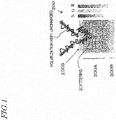
- FIG. 1 schematically shows a cross section of a human skin.
- a skin image contains various information such as spots, wrinkles, pores and nasolabial lines on the skin.
- a skin 200 includes an epidermis 200A present in the depth range of about 0.06 mm or more to 0.2 mm toward the inside from a surface 200S of the skin 200 , and a dermis 200B present on the inner side of the epidermis 200A .
- Spots, wrinkles and pores of the skin have different shapes on the skin and are present at different depth positions in the skin 200 . Therefore, it is possible to selectively extract skin grooves by obtaining images from different depths of the skin and performing an identification operation based on the shape.
- Information of images from different depths of the skin can be obtained by using polarized light or color components. For example, if an image of the skin is captured using linearly-polarized light parallel to a predetermined direction as a light source, the linearly-polarized light is reflected at the surface 200S of the skin while the polarization direction is kept unchanged. On the other hand, linearly-polarized light having been reflected inside the epidermis 200A exits the epidermis 200A with the polarization direction disturbed due to scattering. Thus, if a light source outputting linearly-polarized light is used, and polarized light parallel to the light source is detected (the parallel polarization condition), it is possible to obtain an image with more information from the surface of the skin and less information from the inside of the skin.
- a light source outputting linearly-polarized light is used, and polarized light orthogonal to the light source is detected (the orthogonal polarization condition), it is possible to obtain an image with more information from the inside of the skin and less information from the surface of the skin. That is, by using polarized light as the light source, it is possible to obtain an image that selectively includes information from the inside of the skin or information from the surface of the skin.
- the blue (B) component contains more information from the surface of the skin
- the red (R) and infrared components contain more information from the inside of the epidermis 200A .
- a skin groove, being a target may have a property, such as being able to better absorb light of a particular wavelength region. In such a case, it is possible to accurately extract skin grooves by using light components of that particular wavelength region.
- Wrinkles are present in the vicinity of the surface 200S of the skin 200 .
- an image-capturing operation under the parallel polarization condition, with which it is possible to obtain more information from the surface, and obtaining the difference between the blue pixel value and the red pixel value for each pixel of the image, it is possible to obtain an image containing more information of wrinkles while suppressing the influence of reflection of light at the skin surface.
- a line detection filter such as a Gabor filter
- a threshold process based on the length, the thickness, etc., of the detected portion.
- the present invention is not limited to obtaining the difference between the blue pixel value and the red pixel value, and one may obtain only the blue pixel value or may use pixel values of other colors such as green, for example.
- Eyebrows, eyelashes, a mustache and a beard typically have a lower color saturation and a lower chromaticity than the skin. Therefore, it is possible to extract eyebrows, eyelashes, a mustache and a beard from the captured image through an image process.
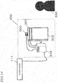
- FIG. 2 is a diagram showing an overall picture of a skin analysis device 305 according to the present embodiment.
- the skin analysis device 305 includes a camera 300 , a lighting device 301 , a control device 302 and a display 303 .
- the display 303 preferably includes a touch panel, and the use may be allowed to control the skin analysis device 305 by touching buttons displayed on the display 303 with a finger, or the like.
- a face image of a user 304 (subject) received from the camera 300 is obtained by the control device 302 and evaluated by the cloud server 307 . Then, skin conditions or indices obtained by quantitatively evaluating the skin conditions are presented on the display 303 .
- FIG. 3(a) is a diagram showing a configuration of the control device 302 .
- the control device 302 includes a microcomputer 302A , a memory 302B and a communication section 302C .
- the microcomputer 302A controls the overall operation of the skin analysis device 305 , including operations to be described below.
- the microcomputer 302A executes various processes to be described below, such as image processes.
- a computer program for controlling various operations of the skin analysis device 305 is stored in the memory 302B .
- the microcomputer 302A controls the operation of various components of the skin analysis device 305 , such as the camera 300 and the lighting device 301 , and executes various processes such as image processes in accordance with the stored computer program.
- the camera 300 captures an image of the face of the user 304 , obtaining face image data.
- the lighting device 301 and the camera 300 may be provided with a polarization filter to thereby obtain images of polarized light.
- the skin analysis device 305 does not need to include the lighting device 301 .
- FIG. 3(b) is a diagram showing a configuration of the cloud server 307 .
- the cloud server 307 includes a microcomputer 307A , a memory 307B , a communication section 307C and a database 307D .
- the cloud server 307 receives, via the communication section 307C , captured images, feature indices of the images, skin evaluation values, etc., from a plurality of skin analysis devices 305 .
- the cloud server 307 stores the various data received from the plurality of skin analysis devices 305 to generate statistical data and obtain correlations between the data. It also transmits, to the skin analysis devices 305 , the statistical data and correlations via the communication section 307C .
- various processes such as image processes for the face image of the user 304 may be performed on the cloud server 307 .
- the evaluation of the face image of the user 304 may be performed on the control device 302 .
- FIG. 4 is a block diagram showing a configuration of the skin analysis device 305 according to the present embodiment.
- the skin analysis device 305 includes the camera 300 , an image obtaining section 1102 , an extraction criterion determination section 1103 , a target extraction section 1104 and the display 303 . Note that it may communicate with the cloud server 307 using a communication section (not shown), and the face image evaluation itself may be done on the cloud server 307 . The evaluation results may be stored in the cloud server 307 .
- the camera 300 captures an image of the face of the user 304 , obtaining the face image.
- the image obtaining section 1102 receives the face image data from the camera 300 to generate horizontally-inverted face image data.
- the generated face image data is output to the display 303 , and the display 303 displays the horizontally-inverted face image. This is a function as an electronic mirror.
- FIG. 12 is a flow chart showing an operation flow of the skin analysis device 305 according to the present embodiment.
- the face detection step S1501 is provided, in addition to the operation flow of Embodiment 1.
- Selection items updated on the user selection database 1911 are transmitted from the communication section 1814 on the cloud server 111 side to the communication section 1803 of the skin analysis device 305 , and the selection items of the extraction criterion selection section 1901 are updated.
- the control device 302 activates the camera 300 , allowing the camera 300 to capture an image of the face of the user.
- the image obtaining section 1102 receives user's face image data from the camera 300 to generate a horizontally-inverted face image.
- the lighting device 301 is activated to capture a user's face image under an illuminated condition.
- the targets are skin grooves and facial hair, it is possible to obtain an image containing more information of skin grooves and facial hair by performing the image-capturing operation under the parallel polarization condition, with which it is possible to obtain more information from the surface, and obtaining the difference between the blue pixel value and the red pixel value for each pixel of the image.
- the face detection section 1401 detects face parts, such as the eyes, the nose, the mouth, the outline, etc., from the user's face image. It also determines the coordinates of a plurality of skin areas of the face image based on the relative position with respect to the detected face parts.
- the selection items which are a plurality of extraction criterion related to each of a plurality of skin areas stored in the extraction criterion selection section 1901 , are presented on the display 303 .
- the user is allowed to select an extraction criterion for each of a plurality of divided skin areas based on the presented selection items. In this process, it is preferred that for each of the plurality of skin areas, the user is allowed to select an extraction criterion from among a plurality of choices displayed on the display 303 .
- the target extraction section 1104 extracts a target from the user's face image based on the target extraction criterion determined in S1202.
- the user selection results from the target selection step are transmitted from the extraction criterion selection section 1901 to the cloud server 111 via the communication section 1803 of the skin analysis device 305 , and received by the communication section 1814 of the cloud server 111 .
- the score s1 is transmitted from the extraction result evaluation section 1902 to the cloud server 111 via the communication section 1803 of the skin analysis device 305 , and received by the communication section 1814 on the cloud server 111 side.
- the selection items having been updated based on the user selection database 1911 are transmitted from the communication section 1814 on the cloud server 111 side to the communication section 1803 of the skin analysis device 305 , updating the selection items of the extraction criterion selection section 1901 .
- the average b2 of the evaluation results and the variance c2 of the evaluation results having been updated based on the evaluation result database 1912 are transmitted from the communication section 1814 of the cloud server 111 to the communication section 1803 of the skin analysis device 305 , and the score conversion coefficients b1 and c1 of the extraction result evaluation section are updated based on the average b2 of the evaluation results and the variance c2 of the evaluation results.
- coefficients such as the selection items and the average and the variance of the evaluation results, may be updated based on data of all users, or based on partial data depending on the user's attributes, or based on data of only one user.
- FIG. 18(a) is a diagram showing an overall picture of a service provided by an information management system according to the present embodiment.
- the information management system includes a group 100 , a data center management company 110 and a service provider 120 .
- the group 100 is, for example, a corporate, an organization, a household, etc., whose size is not relevant.
- the group 100 includes a plurality of appliances 101 and a home gateway 102 , the appliances 101 including a first appliance and a second appliance.
- the plurality of appliances 101 include appliances that can be connected to the Internet (e.g., a smartphone, a personal computer (PC), a television, or the like), and appliances that cannot themselves be connected to the Internet (e.g., a lighting device, a washing machine, a refrigerator, or the like).
- the plurality of appliances 101 may include appliances that cannot themselves be connected to the Internet but can be connected to the Internet via the home gateway 102 .
- a user 10 uses the plurality of appliances 101 in the group 100 .
- the appliances 101 include a skin analysis device 305 according to one of Embodiments 1 to 3.
- the data center management company 110 includes the cloud server 111 .
- the cloud server 111 is a virtualization server that connects with various appliances via the Internet. Primarily, the cloud server 111 manages huge data (big data) that is difficult to handle with an ordinary database management tool, or the like.
- the data center management company 110 is responsible for management of data, management of the cloud server 111 , operation of a data center that is responsible for such management, etc. The details of the services provided by the data center management company 110 will be described later.
- the service provider 120 includes a server 121 .
- the scale of the server 121 as used herein is not relevant, and the server 121 may be a memory of a personal-use PC, for example. In some cases, the service provider 120 does not include the server 121 .
- the home gateway 102 is not essential. For example, in cases where the cloud server 111 is responsible for all the data management, there is no need for the home gateway 102 . There may be no appliances that cannot themselves be connected to the Internet, e.g., where all the appliances in a house are connected to the Internet.
- log information refers to information indicating the status of operation, the date of operation, etc., of the plurality of appliances 101 , for example.
- log information includes a viewing history of a television, recording programming information of a recorder, dates and times of operation of a washing machine, the amounts of laundry of a washing machine, dates and times the door of a refrigerator has been opened and closed, the number of times the door of a refrigerator has been opened and closed, etc.
- log information also includes extraction criteria, etc., described above in Embodiments 1 to 3, in addition to the dates and times of operation of the skin analysis device 305 .
- Log information is not limited to these information, but may also include various information that can be obtained from various appliances. Note that log information may be provided directly from the plurality of appliances 101 themselves to the cloud server 111 via the Internet. Log information may be once sent from the plurality of appliances 101 and accumulated in the home gateway 102 , and then provided to the cloud server 111 from the home gateway 102 .
- the cloud server 111 of the data center management company 110 provides the accumulated log information by a certain unit to the service provider 120 .
- the certain unit may be a unit by which the data center management company 110 is able to rearrange and provide the accumulated information to the service provider 120 , or may be a unit by which the accumulated information is requested by the service provider 120 .
- the information is described to be provided by a certain unit, it may not be a certain unit, and the amount of information to be provided may vary depending on circumstances.
- the log information is stored in the server 121 owned by the service provider 120 as necessary (arrow 132 of FIG. 18(a) ).
- the user 10 may be different from or the same as the user 20 .
- the techniques described in the embodiments above may be implemented the following types of cloud service, for example. However, types of the cloud service for implementing the techniques described in the embodiments above are not limited thereto.
- FIG. 19 is a diagram showing an overall picture of a service provided by an information management system of service type 1 (on-premise data center-type cloud service).
- a service provider 120 obtains information from a group 100 , and provides a service to the user.
- the service provider 120 has the function of a data center management company. That is, the service provider 120 owns a cloud server 203 for managing big data. Therefore, there is no data center management company.
- the service provider 120 operates and manages the data center (cloud server) 203 .
- the service provider 120 manages an operating system (OS) 202 and an application 201 .
- the service provider 120 provides a service (arrow 204 ) using the OS 202 and the application 201 managed by the service provider 120 .
- FIG. 20 is a diagram showing an overall picture of a service provided by an information management system of service type 2 (IaaS-based cloud service).
- IaaS stands for Infrastructure as a Service, referring to a cloud service provision model in which the infrastructure for constructing and running a computing system itself is provided as a service via the Internet.
- a data center management company 110 operates and manages the data center (cloud server) 203 .
- the service provider 120 manages the OS 202 and the application 201 .
- the service provider 120 provides a service (arrow 204 ) using the OS 202 and the application 201 managed by the service provider 120 .
- FIG. 21 is a diagram showing an overall picture of a service provided by an information management system of service type 3 (IaaS-based cloud service).
- IaaS-based cloud service an information management system of service type 3
- PaaS stands for Platform as a Service, referring to a cloud service provision model in which the platform serving as a foundation for constructing and running software is provided as a service via the Internet.
- the data center management company 110 manages the OS 202 , and operates and manages the data center (cloud server) 203 .
- the service provider 120 manages the application 201 .
- the service provider 120 provides a service (arrow 204 ) using the OS 202 managed by the data center management company 110 and the application 201 managed by the service provider 120 .
- FIG. 22 is a diagram showing an overall picture of a service provided by an information management system of service type 4 (SaaS-based cloud service).
- SaaS stands for Software as a Service.
- the SaaS-based cloud service is, for example, a cloud service provision model having a function of allowing applications provided by a platform provider that owns a data center (cloud server) to be used, via a network such as the Internet, by users, such as corporates and individuals, who do not own a data center (cloud server).
- the data center management company 110 manages the application 201 , manages the OS 202 , and operates and manages the data center (cloud server) 203 .
- the service provider 120 provides a service (arrow 204 ) using the OS 202 and the application 201 managed by the data center management company 110 .
- the service provider 120 provides a service.
- the service provider or the data center management company may develop, by themselves, an OS, an application, a database for big data, etc., or may outsource the development to a third party.
- the skin analysis method, the skin analysis device, and the method for controlling a skin analysis device disclosed in the present application can suitably be used in analyzing and evaluating skin areas by means of a skin analysis device.
Landscapes
- Health & Medical Sciences (AREA)
- Engineering & Computer Science (AREA)
- Life Sciences & Earth Sciences (AREA)
- Physics & Mathematics (AREA)
- General Health & Medical Sciences (AREA)
- Medical Informatics (AREA)
- Public Health (AREA)
- Pathology (AREA)
- Biophysics (AREA)
- Biomedical Technology (AREA)
- Heart & Thoracic Surgery (AREA)
- Molecular Biology (AREA)
- Surgery (AREA)
- Animal Behavior & Ethology (AREA)
- Veterinary Medicine (AREA)
- Oral & Maxillofacial Surgery (AREA)
- General Physics & Mathematics (AREA)
- Theoretical Computer Science (AREA)
- Human Computer Interaction (AREA)
- Multimedia (AREA)
- Dermatology (AREA)
- Computer Vision & Pattern Recognition (AREA)
- Nuclear Medicine, Radiotherapy & Molecular Imaging (AREA)
- Radiology & Medical Imaging (AREA)
- Dentistry (AREA)
- Geometry (AREA)
- Quality & Reliability (AREA)
- Measurement Of The Respiration, Hearing Ability, Form, And Blood Characteristics Of Living Organisms (AREA)
- Measuring And Recording Apparatus For Diagnosis (AREA)
Abstract
Description
- The present application relates to a skin analysis method, a skin analysis device, and a method for controlling a skin analysis device.
- There are conventional techniques for analyzing the skin condition based on a captured image of the skin so as to visualize and quantify the analysis results. For this, it is necessary to extract objects to be analyzed that are present on the skin surface based on the skin image.
- Patent Document No. 1 discloses a technique for extracting skin texture and/or wrinkles from an obtained skin image by performing image processes, including a cross binarization process and/or a short-line segment matching process.
- Patent Document No. 2 discloses a technique for extracting skin grooves by converting the brightness values of pixels so that the variance in brightness value of the captured image is greater than or equal to a predetermined value, binarizing each pixel, and performing a matching operation between binarized black pixels and predetermined short-line segments.
- Non-Patent Document No. 1 discloses a technique for extracting wrinkles by predetermining the edge direction of the skin based on local features, and performing a filtering process using a Gabor filter having a predetermined orientation.
-
- [Patent Document No. 1] International Publication
WO 09/142069 - [Patent Document No. 2] Japanese Patent No.
4909686 - [Non-Patent Document No. 1] Cula et al., "Assessing facial wrinkles: automatic detection and quantification", Skin Research and Technology 2013
- However, analyzing the skin surface requires troublesome operations or a large device, and analysis based on arbitrary face images is said to require further researches.
- A control method for controlling a skin analysis device disclosed in the present application is a control method for controlling a skin analysis device, the skin analysis device including a camera for obtaining a face image of a subject, a display for displaying the face image of the subject, and a computer, wherein: the control method causes the computer of the skin analysis device to execute: obtaining the face image of the subject; determining a target extraction criterion for each of a plurality of skin areas of the face image based on a position on the face image; extracting a target that satisfies the determined extraction criterion from the face image; and displaying the extracted target on the display of the skin analysis device.
- According to the skin analysis method and the skin analysis device disclosed in the present application, it is possible to automatically perform, for the entire face, an arbitrary skin wrinkle detection responsive to the user's demand.
-
- [
FIG. 1 ] A diagram schematically showing a structure inside the skin. - [
FIG. 2 ] A diagram showing an overall picture of a skin analysis device according to Embodiment 1 of the present disclosure. - [
FIG. 3 ] (a) is a diagram showing a configuration of acontrol device 302, and (b) is a diagram showing a configuration of acloud server 307. - [
FIG. 4 ] A functional block diagram of a skin analysis device according to Embodiment 1 of the present disclosure. - [
FIG. 5 ] A flow chart showing a procedure for skin evaluation using a skin analysis device according to Embodiment 1 of the present disclosure. - [
FIG. 6 ] (a) is a diagram showing an example display screen image to be displayed on the display before skin analysis, and (b) is a diagram showing an example display screen image to be displayed on the display during an image-capturing operation. - [
FIG. 7 ] (a), (b) and (c) are diagrams each schematically showing the process in progress for determining and extracting target features based on their positions on the image. - [
FIG. 8 ] (a) and (b) are diagrams each showing an example display screen image to be displayed on the display after skin analysis. - [
FIG. 9 ] (a) and (b) are diagrams each showing an example display screen image to be displayed on the display. - [
FIG. 10 ] (a) and (b) are diagrams each showing an example display screen image to be displayed on the display. - [
FIG. 11 ] A functional block diagram of a skin analysis device according to Embodiment 2 of the present disclosure. - [
FIG. 12 ] A flow chart showing a procedure for skin evaluation using a skin analysis device according to Embodiment 2 of the present disclosure. - [
FIG. 13 ] (a), (b) and (c) are diagrams each schematically showing the process in progress for determining and extracting target features based on a feature point of the face. - [
FIG. 14 ] A diagram showing an overall picture of a skin analysis device according to Embodiment 3 of the present disclosure. - [
FIG. 15 ] A diagram showing a configuration of a cloud server and a skin analysis device according to Embodiment 3 of the present disclosure. - [
FIG. 16 ] A functional block diagram of a cloud server and a skin analysis device according to Embodiment 3 of the present disclosure. - [
FIG. 17 ] A flow chart showing a procedure for skin evaluation using a skin analysis device according to Embodiment 3 of the present disclosure. - [
FIG. 18 ] (a) is a diagram showing an overall picture of an information provision system according to Embodiment 4, and (b) and (c) are diagrams each showing a configuration of a data center. - [
FIG. 19 ] A diagram showing an overall picture of a service provided by an information management system of service type 1 (on-premise data center-type cloud service). - [
FIG. 20 ] A diagram showing an overall picture of a service provided by an information management system of service type 2 (IaaS-based cloud service). - [
FIG. 21 ] A diagram showing an overall picture of a service provided by an information management system of service type 3 (PaaS-based cloud service). - [
FIG. 22 ] A diagram showing an overall picture of a service provided by an information management system of service type 4 (SaaS-based cloud service). - The technique disclosed in Non-Patent Document No. 1 uses a Gabor filter to extract wrinkles (skin grooves) in the skin image of the user so as to evaluate the skin condition based on the extracted wrinkles. Here, the Gabor filter determines a particular orientation, and extracts wrinkles running toward the determined orientation.
- With the technique disclosed in Non-Patent Document No. 1, however, a predetermined portion is cropped from a face image, and the evaluation is performed for the cropped image. Since it is a specialist who crops the image, it is not possible for the user himself/herself to casually evaluate the skin condition from a face image. With the technique disclosed in Non-Patent Document No. 1, the orientation of the Gabor filter is determined based on local features of the image, i.e., the direction on the skin of the user in which wrinkles (skin grooves) are running conspicuously. Therefore, even if the user wishes an evaluation of wrinkles on the nostrils on the face image, for example, conspicuous nasolabial lines may be detected from the face image, i.e., the type of wrinkles detected may not coincide with the type of wrinkles the user wishes to be evaluated.
- Particularly, no researches have been undertaken on technical solutions for satisfying the need of each user wishing to have a different type of wrinkles evaluated, depending on the position on the face image of which the skin condition is evaluated.
- In view of these problems, the inventors of the present application have arrived at a novel skin analysis method, a novel skin analysis device, and a novel method for controlling a skin analysis device. The skin analysis method, the skin analysis device and the method for controlling a skin analysis device of the present application are outlined below.
- one embodiment of a control method for controlling a skin analysis device disclosed in the present application is a control method for controlling a skin analysis device, the skin analysis device including a camera for obtaining a face image of a subject, a display for displaying the face image of the subject, and a computer, wherein: the control method causes the computer of the skin analysis device to execute: obtaining the face image of the subject; determining a target extraction criterion for each of a plurality of skin areas of the face image based on a position on the face image; extracting a target that satisfies the determined extraction criterion from the face image; and displaying the extracted target on the display of the skin analysis device.
- In the present embodiment, the control method causes the computer of the skin analysis device to determine a target extraction criterion for each of a plurality of skin areas of the face image based on a position on the face image. Therefore, there is no longer a need for a specialist to perform an operation (cropping a face image) for the skin area analysis of extracting a target, and it is therefore possible for the user to analyze and evaluate the skin area only by preparing a face image.
- The control method causes the computer to execute: detecting a face part included in the obtained face image; determining the plurality of skin areas each based on a relative position on the face image with respect to the detected face part; and determining the target extraction criterion for the plurality of skin areas determined. That is, a target extraction criterion is determined based on where the skin area is located in the face image. Therefore, it is possible to extract a target using a different extraction criterion depending on the location of the skin area, e.g., using different extraction criteria for targets around the eyes and for targets around the mouth of the face image, for example.
- In the embodiment above, for example, the control method may cause the computer to execute: displaying, on the display, a plurality of target extraction criteria for one of the plurality of skin areas in accordance with the relative position in such a manner that one of the extraction criteria can be selected; when it is determined that one of the plurality of extraction criteria has been selected, extracting a target that satisfies the selected extraction criterion; and displaying the extracted target on the display.
- According to the embodiment above, it is possible to evaluate a different type of wrinkles for each user, depending on the position of the skin area on the face image for which the skin condition is to be evaluated.
- It is also possible to prevent a problem in which the type of wrinkles detected does not coincide with the type of wrinkles the user desires to be evaluated, e.g., where conspicuous nasolabial lines are detected from the face image even though the user desires to have an evaluation of the nostrils wrinkles on the face image.
- In the embodiment above, for example, the target may be a skin groove and/or facial hair.
- In the embodiment above, for example, the extraction criterion may be a value representing at least one of an angle, a thickness and a length of the target.
- In the embodiment above, for example, the relative position with respect to a face part may be any one of the glabellar area, the under-the-eye area, the lateral canthus area, the medial canthus area, the nose-side area, the mouth area and the forehead, or may be any combination thereof.
- In the embodiment above, for example, the extracted target may be displayed on the display while being superimposed over the face image.
- In the embodiment above, for example, the target that satisfies the determined extraction criterion may be extracted by a filtering process; and the extraction criterion may be a property of a filter used in the filtering process.
- In the embodiment above, for example, the target may be extracted based on a predetermined extraction criterion stored while being associated with a relative position between the face part and the plurality of skin areas.
- In the embodiment above, for example, the predetermined extraction criterion may be stored in a memory of the skin analysis device.
- In the embodiment above, for example, the predetermined extraction criterion may be stored in a server that can be accessed by the skin analysis device via a network.
- In the embodiment above, for example, the number of times one of the plurality of extraction criteria has been selected may be stored in a server that can be accessed by the skin analysis device via a network, and the predetermined extraction criterion may be determined based on a selected frequency.
- One embodiment of a skin evaluation method disclosed in the present application includes: obtaining a face image of a subject; determining a target extraction criterion for each of a plurality of skin areas of the face image based on a position on the face image; extracting a target that satisfies the determined extraction criterion from the face image; and displaying the extracted target on a display.
- In the embodiment above, for example, the method may include: displaying, on the display, a plurality of target extraction criteria for one of the plurality of skin areas in accordance with the relative position in such a manner that one of the extraction criteria can be selected; when it is determined that one of the plurality of extraction criteria has been selected, extracting a target that satisfies the extraction criterion; and displaying the extracted target on the display.
- In the embodiment above, for example, the target may be a skin groove and/or facial hair.
- In the embodiment above, for example, the extraction criterion may be a value representing one of an angle, a thickness and a length of the target.
- In the embodiment above, for example, the relative position with respect to a face part may be any one of the glabellar area, the under-the-eye area, the lateral canthus area, the medial canthus area, the nose-side area, the mouth area and the forehead, or may be any combination thereof.
- In the embodiment above, for example, the target that satisfies the determined extraction criterion may be extracted by a filtering process; and the extraction criterion may be a property of a filter used in the filtering process.
- One embodiment of a computer program for controlling a skin analysis device disclosed in the present application is a computer program for controlling a skin analysis device, the skin analysis device including a camera for obtaining a face image of a subject, a display for displaying the image of the subject, and a computer, wherein: the computer program causes the computer of the skin analysis device to execute: obtaining the face image of the subject; determining a target extraction criterion for each of a plurality of skin areas of the face image based on a position on the face image; extracting a target that satisfies the determined extraction criterion from the face image; and displaying the extracted target on the display of the skin analysis device.
- This makes it possible to extract a different skin condition depending on the position on the face image that is captured in alignment with a predetermined guide, for example.
- In the embodiment above, the computer program causes the computer to execute: detecting a face part included in the obtained face image; determining the plurality of skin areas each based on a relative position on the face image with respect to the detected face part; and determining the target extraction criterion for the plurality of skin areas determined. This makes it possible to extract a different skin condition depending on the position of the face part included in the face image that is captured while the user pays no particular attention to the position.
- The extraction criterion is determined based on an updatable database which is predetermined based on the relative position with respect to the face part. This makes it possible to extract based on the tendency of a skin condition that is desired by many users of the skin analysis device.
- Targets are extracted based on the extraction criterion selected by the user based on the position in the image. This makes it possible to extract a skin condition that is desired by the currently-operating user.
- Thus, according to the above embodiment of the present application, it is possible to automatically perform, for the entire face, the detection of any skin wrinkles in accordance with user requests.
- One embodiment of a skin analysis device disclosed in the present application includes: a camera for obtaining a face image of a subject; an extraction criterion determination section for determining a target extraction criterion for each of a plurality of skin areas of the face image based on a position on the face image; a target extraction section for extracting a target that satisfies the determined extraction criterion from the face image; and a display for displaying the extracted target on a display.
- In the embodiment above, the skin analysis device further includes a face detection section for detecting a face part included in the face image, and determining the plurality of skin areas each based on a relative position on the face image with respect to the detected face part.
- In the embodiment above, the skin analysis device further includes: an extraction criterion selection section for displaying a plurality of extraction criteria related to each of the plurality of skin areas on the display, and accepting one selection; an extraction result evaluation section for converting a target extracted from each of the plurality of skin areas into a score; and a communication section for transmitting the selection result of the extraction criterion selection section and the score to an external server.
- The following embodiments each illustrate a specific example of the present invention. Numerical values, shapes, components, steps, orders of steps, etc., to be used in the following embodiments are illustrative and are not to limit the scope of the present invention. Those components introduced in the following embodiments that are not recited in the independent claim(s) representing the most superordinate concept are illustrated herein as optional components. Particulars of any embodiment can be combined with those of any other embodiment.
- A skin analysis device and a method for controlling the same according to the present embodiment will now be described with reference to the drawings. Each of the skin analysis devices of the embodiments of the present specification captures an image of the face of the subject so as to extract and display skin grooves and facial hair present in a skin area. Skin grooves refer to wrinkles of various lengths, thicknesses and depths, including nasolabial lines. Facial hair includes eyebrows, eyelashes, a mustache and a beard. Skin grooves and facial hair will be referred to as targets. The skin area refers to a selected part of the entire skin including those parts covered by the facial hair.
- First, an image-capturing method for capturing an image of the face of the subject and accurately extracting skin grooves and facial hair present in the skin area will be described.
FIG. 1 schematically shows a cross section of a human skin. A skin image contains various information such as spots, wrinkles, pores and nasolabial lines on the skin. As shown inFIG. 1 , askin 200 includes anepidermis 200A present in the depth range of about 0.06 mm or more to 0.2 mm toward the inside from asurface 200S of theskin 200, and adermis 200B present on the inner side of theepidermis 200A. Spots, wrinkles and pores of the skin have different shapes on the skin and are present at different depth positions in theskin 200. Therefore, it is possible to selectively extract skin grooves by obtaining images from different depths of the skin and performing an identification operation based on the shape. - Information of images from different depths of the skin can be obtained by using polarized light or color components. For example, if an image of the skin is captured using linearly-polarized light parallel to a predetermined direction as a light source, the linearly-polarized light is reflected at the
surface 200S of the skin while the polarization direction is kept unchanged. On the other hand, linearly-polarized light having been reflected inside theepidermis 200A exits theepidermis 200A with the polarization direction disturbed due to scattering. Thus, if a light source outputting linearly-polarized light is used, and polarized light parallel to the light source is detected (the parallel polarization condition), it is possible to obtain an image with more information from the surface of the skin and less information from the inside of the skin. If a light source outputting linearly-polarized light is used, and polarized light orthogonal to the light source is detected (the orthogonal polarization condition), it is possible to obtain an image with more information from the inside of the skin and less information from the surface of the skin. That is, by using polarized light as the light source, it is possible to obtain an image that selectively includes information from the inside of the skin or information from the surface of the skin. - The longer the wavelength, the further inside of the
epidermis 200A light from the light source travels and is reflected. Therefore, of the captured image of the skin, the blue (B) component contains more information from the surface of the skin, and the red (R) and infrared components contain more information from the inside of theepidermis 200A. - A skin groove, being a target, may have a property, such as being able to better absorb light of a particular wavelength region. In such a case, it is possible to accurately extract skin grooves by using light components of that particular wavelength region.
- Wrinkles are present in the vicinity of the
surface 200S of theskin 200. By performing an image-capturing operation under the parallel polarization condition, with which it is possible to obtain more information from the surface, and obtaining the difference between the blue pixel value and the red pixel value for each pixel of the image, it is possible to obtain an image containing more information of wrinkles while suppressing the influence of reflection of light at the skin surface. By processing an image using a line detection filter such as a Gabor filter, it is possible to obtain an image containing more information of wrinkles and nasolabial lines. For accurately distinguishing between wrinkles and nasolabial lines from each other, one may further perform a threshold process based on the length, the thickness, etc., of the detected portion. - Note that although obtaining the difference between the blue pixel value and the red pixel value has been described above for obtaining an image containing more information of wrinkles, the present invention is not limited to obtaining the difference between the blue pixel value and the red pixel value, and one may obtain only the blue pixel value or may use pixel values of other colors such as green, for example.
- Eyebrows, eyelashes, a mustache and a beard typically have a lower color saturation and a lower chromaticity than the skin. Therefore, it is possible to extract eyebrows, eyelashes, a mustache and a beard from the captured image through an image process.
-
FIG. 2 is a diagram showing an overall picture of askin analysis device 305 according to the present embodiment. Theskin analysis device 305 includes acamera 300, alighting device 301, acontrol device 302 and adisplay 303. Herein, thedisplay 303 preferably includes a touch panel, and the use may be allowed to control theskin analysis device 305 by touching buttons displayed on thedisplay 303 with a finger, or the like. - A face image of a user 304 (subject) received from the
camera 300 is obtained by thecontrol device 302 and evaluated by thecloud server 307. Then, skin conditions or indices obtained by quantitatively evaluating the skin conditions are presented on thedisplay 303. -
FIG. 3(a) is a diagram showing a configuration of thecontrol device 302. Thecontrol device 302 includes amicrocomputer 302A, amemory 302B and acommunication section 302C. Themicrocomputer 302A controls the overall operation of theskin analysis device 305, including operations to be described below. Themicrocomputer 302A executes various processes to be described below, such as image processes. For example, a computer program for controlling various operations of theskin analysis device 305 is stored in thememory 302B. Themicrocomputer 302A controls the operation of various components of theskin analysis device 305, such as thecamera 300 and thelighting device 301, and executes various processes such as image processes in accordance with the stored computer program. - The
camera 300 captures an image of the face of theuser 304, obtaining face image data. As described above, in order to accurately extract wrinkles, facial hair, and the like (targets) from the user's face image, thelighting device 301 and thecamera 300 may be provided with a polarization filter to thereby obtain images of polarized light. Note that theskin analysis device 305 does not need to include thelighting device 301. -
FIG. 3(b) is a diagram showing a configuration of thecloud server 307. Thecloud server 307 includes amicrocomputer 307A, amemory 307B, acommunication section 307C and adatabase 307D. Thecloud server 307 receives, via thecommunication section 307C, captured images, feature indices of the images, skin evaluation values, etc., from a plurality ofskin analysis devices 305. Thecloud server 307 stores the various data received from the plurality ofskin analysis devices 305 to generate statistical data and obtain correlations between the data. It also transmits, to theskin analysis devices 305, the statistical data and correlations via thecommunication section 307C. - Note that various processes such as image processes for the face image of the
user 304 may be performed on thecloud server 307. The evaluation of the face image of theuser 304 may be performed on thecontrol device 302. -
FIG. 4 is a block diagram showing a configuration of theskin analysis device 305 according to the present embodiment. Theskin analysis device 305 includes thecamera 300, animage obtaining section 1102, an extractioncriterion determination section 1103, atarget extraction section 1104 and thedisplay 303. Note that it may communicate with thecloud server 307 using a communication section (not shown), and the face image evaluation itself may be done on thecloud server 307. The evaluation results may be stored in thecloud server 307. - An operation of the
skin analysis device 305 of the present invention will now be described with reference to the drawings. - The
skin analysis device 305 of the present embodiment starts its operation with theuser 304 being located in front of thecamera 300 of theskin analysis device 305. - First, the
camera 300 captures an image of the face of theuser 304, obtaining the face image. Theimage obtaining section 1102 receives the face image data from thecamera 300 to generate horizontally-inverted face image data. The generated face image data is output to thedisplay 303, and thedisplay 303 displays the horizontally-inverted face image. This is a function as an electronic mirror. - Looking at the face image displayed on the
display 303, the user adjusts the position of the face image on thedisplay 303. If the face image of himself/herself is not displayed generally at the center of thedisplay 303, or if the face image is too large or too small, the user moves the position of the face with respect to thecamera 300 so that the face image is displayed on thedisplay 303 with a suitable size and at a suitable position. A guide marker, indicating a desirable face position, may be displayed on thedisplay 303 so as to make it easier for the user to adjust the position of the face. In response to the user's instruction to start the image-capturing operation, theskin analysis device 305 starts the operation of analyzing the captured face image. -
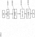
FIG. 5 is a flow chart showing an operation flow of theskin analysis device 305. - The
control device 302 activates thecamera 300, allowing thecamera 300 to capture an image of the face of the user. Theimage obtaining section 1102 receives user's face image data from thecamera 300 to generate a horizontally-inverted face image. In this process, it is preferred that thelighting device 301 is activated to capture a user's face image under an illuminated condition. The polarization condition and the wavelength of the light to be used are selected depending on the type of targets to be extracted, as described above. If the targets are skin grooves and facial hair, it is possible to obtain an image containing more information of skin grooves and facial hair by performing the image-capturing operation under the parallel polarization condition, with which it is possible to obtain more information from the surface, and obtaining the difference between the blue pixel value and the red pixel value for each pixel of the image. - The extraction
criterion determination section 1103 receives the horizontally-inverted face image data from theimage obtaining section 1102, and determines the target extraction criterion based on the position on the face image. Herein, an extraction criterion of a target refers to a value representing a feature of the target as will be described in detail below. - The
target extraction section 1104 extracts a target from the user's face image based on the target extraction criterion determined in S1202. - The
display 303 displays the target extracted in S1203. In this process, the displayed target is preferably displayed while being superimposed over the user's face image. - The operation of the
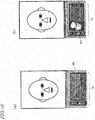
skin analysis device 305 will now be described in greater detail, with reference to illustrative images to be displayed on thedisplay 303.FIG. 6(a) shows an example initial screen image displayed on thedisplay 303 of theskin analysis device 305 before capturing a user's face image. For example, the display area of thedisplay 303 includes themain screen 70 having a large area, and thesub screen 72 having a small area located below themain screen 70. The initial screen includes an image received from thecamera 300, which is displayed in real time on themain screen 70, thereby functioning as a digital mirror. Information such as a clock or weather forecast may be displayed, for example, on thesub screen 72. -
FIG. 6(b) shows the screen image immediately before the start of an image-capturing operation. A touch panel is provided on the surface of thedisplay 303 as described above, and control menu items and menu items for selecting functions are displayed in theupper portion 80 and theleft side portion 78 of thesub screen 72 in response to the user touching the touch panel with a finger, or the like. Themain screen 70 may show aguide 35 for guiding the position of the face of the user, for example. A mark indicating the image-capturing timing, anumber 74 counting down to the image-capturing operation, etc., may be displayed. - For example, the
face image 31 of the user received from thecamera 300 is displayed in real time in theright half 72R of thesub screen 72, and a calendar is displayed in theleft half 72L. The calendar may include a mark, or the like, indicating that an image was captured in the past using theskin analysis device 305, for example. After the display ofFIG. 6(b) , an image of the face of the user is captured as described above. - A method for determining the target extraction criterion from the user's face image and a method for extracting a target based on the determined extraction criterion will now be described.
-
FIG. 7(a) to (c) are diagrams each schematically showing the process in progress for determining the feature of the target of which the skin condition is to be extracted, based on the position on the user's face image, and extracting the target based on the determined target's feature. In order to determine the extraction criterion of the target based on the position on the face image, the face image is divided into quadrants in the present embodiment, and the extraction criterion is determined for each quadrant.FIG. 7(a) shows the user's face image divided into quadrants, andFIG. 7(b) schematically shows target features as line segments where the target extraction criterion has been determined for each of the third quadrant and the fourth quadrant. The extraction criterion illustrated herein indicates the direction of wrinkles and facial hair (targets).FIG. 7(c) schematically shows wrinkles that have been extracted from the face image based on the determined target feature. - In the target extraction criterion determination step S1202, the user's face image obtained by the
image obtaining section 1102 is output to the extractioncriterion determination section 1103. The target extraction criterion is determined based on the position on the image as illustrated inFIGS. 7(a) and (b) . The extraction criterion is a value representing at least one of the angle, the thickness, the length (size) of the target. For example, in the example shown inFIG. 7(b) , no extraction criterion is set for the first and second quadrants, of the four quadrants into which the face image is vertically and horizontally divided. The angle of the target is set as an extraction criterion for the third and fourth quadrants. More specifically, with respect to the boundary between the first quadrant and the fourth quadrant, an angular criterion of 45 degrees is set for the third quadrant, and an angular criterion of -45 degrees (135 degrees) is set for the fourth quadrant. In such a case, the extraction criterion is determined to be within a range of ±10 degrees of the determined angular criterion, for example. - In the target extraction step S1203, the user's face image obtained by the
image obtaining section 1102, and the extraction criterion determined by the extractioncriterion determination section 1103 are output to thetarget extraction section 1104. The target extraction section extracts the target based on the user's face image and the target extraction criterion. Specifically, since no extraction criterion is set for the first and second quadrants of the face image, targets satisfying the extraction criterion are not extracted. On the other hand, in the third and fourth quadrants, wrinkles satisfying the extraction criterion described above are extracted. Therefore, as shown inFIG. 7(c) , the nasolabial lines and wrinkles under the eyes extending in the same direction as the nasolabial lines are extracted. - When extracting linear targets, such as skin grooves, from the face image, it is not possible to properly extract targets if there is no match for the direction, which is one of the target extraction criteria. For example, the nasolabial line located in the third quadrant of the face image and the nasolabial line in the fourth quadrant extend in different directions from each other, and if an extraction condition suitable for extraction from one quadrant is used, control may fail to properly extract from the other quadrant. According to the present embodiment, it is possible to properly extract wrinkles extending in different directions including the two nasolabial lines since extraction criteria of targets in a plurality of skin areas of the face image are determined based on the positions on the face image.
- While wrinkles under the eyes and the nasolabial lines are extracted in the example shown in
FIG. 7(c) , the thickness of the target may be set as the extraction condition. In such a case, either one of them can be selectively extracted. - The target extraction can be performed by methods using the pattern matching disclosed in Patent Document Nos. 1 and 2, methods using the Gabor filter disclosed in Non-Patent Document No. 1, methods using the Hough transform, etc. Alternatively, a Sobel filter may be used, and other segment extraction methods and filters may be used.
- When a Gabor filter is used, for example, parameters such as the x-direction spatial frequency, the y-direction spatial frequency, the filter size, etc., of the filter are determined based on the angular criteria set for the third quadrant and the fourth quadrant described above.
- In the extraction result display step S1204, the user's face image obtained by the
image obtaining section 1102 and the extraction results for the target extracted by thetarget extraction section 1104 are output to adisplay 1105. Thedisplay 1105 displays the result screen image as illustrated inFIG. 8(a) and FIG. 8(b) is displayed on thedisplay 303. - In the display example shown in
FIG. 8(a) , the user's face image used for extracting wrinkles (targets), and extractedtargets 81 are displayed on themain screen 70 while being superimposed over the face image. The user's face image is also shown in theleft half 72L of thesub screen 72. Menu items for specifying face positions are displayed in anupper portion 80 of thesub screen 72, and menu items for switching between content to be displayed and functions are displayed in theleft side portion 78. For example, the user can have a particular skin area of the face displayed and can change content to be displayed by touching theupper portion 80 and the left side portion 7B of thesub screen 72. -
FIG. 8(b) shows an example where a portion of the image of the skin area, which is anarea 83 designated by the user, is displayed, on an enlarged scale, in theright half 72R of thesub screen 72. Wrinkles (targets) are also displayed in theright half 72R. Targets may be displayed by for example displaying portions of the skin area corresponding to the targets as red areas (lines). - Note that control may not only display the extracted targets, but also evaluate the extracted targets and present the results of the evaluation. For example, where targets are extracted from the face image in accordance with the procedure described above, the evaluation results calculated for the targets are shown in a radar chart, for example, as shown in the
right half 72R of thesub screen 72 ofFIG. 8(a) . For example, control may obtain the density of wrinkles (targets) and display the results of the evaluation. - Moreover, a history of information on the extracted targets and the scores shown in a radar chart may be stored in the
control device 302 or thecloud server 307. This allows the user to refer to the evaluation result history at any time, which may be helpful for a chronologically-planned skin care. - For example, a calendar may be displayed on the
sub screen 72 as shown inFIG. 9(a) . Information is displayed on the calendar that indicates whether or not an evaluation was done for each date. For example, when the user selects a date on the calendar, the past evaluation results as shown in the display example ofFIG. 9(b) are displayed on thedisplay 303. In this process, the user's face image, which was evaluated on the selected date, is displayed on themain screen 70, together with the targets which were extracted, and thesub screen 72 displays the calendar together with the extracted targets having been converted into a score, which is shown in a radar chart. - Moreover, based on the evaluation results and the history, there may be presented advice information which is related to skin care optimized for the individual's skin condition and recommended skin care and cosmetic products. As shown in
FIG. 10(a) , there may be displayed advice which is related to esthetics such as skin treatment based on the evaluation results. Information of cosmetics and beauty appliances for improving the skin condition may also be displayed in detail, as shown inFIG. 10(b) . - In the present embodiment, control detects a face part included in the face image and determines a skin area based on a relative position with respect to the detected face part so as to set a target extraction criterion.
-
FIG. 11 is a block diagram showing a configuration of theskin analysis device 305 according to the present embodiment. Aface detection section 1401 is provided, in addition to the configuration of Embodiment 1. Theface detection section 1401 detects face parts such as the eyes, the nose, the mouth, the outline, etc., from the user's face image, and determines the coordinates of a plurality of skin areas of the face image based on the relative position with respect to the detected face parts. -
FIG. 12 is a flow chart showing an operation flow of theskin analysis device 305 according to the present embodiment. The face detection step S1501 is provided, in addition to the operation flow of Embodiment 1. -
FIG. 13 shows a schematic diagram where the target feature is determined based on the face detection position.FIG. 13(a) shows a state where face parts, such as the eyes, the nose, the mouth, the outline, etc., have been detected from the user's face image. The detection of these face parts can be done utilizing known face recognition techniques used in digital cameras, etc.FIG. 13(b) shows how a target extraction criterion is determined for each skin area based on its relative positional relationship with the detected face parts. A skin area defined based on its relative positional relationship with face parts may be, for example, any of the glabellar area, the under-the-eye area, the lateral canthus area, the medial canthus area, the nose-side area, the mouth area and the forehead. It may also be any combination thereof. - For example, the figure shows the orientation of a Gabor filter where targets are extracted by using a Gabor filter. For example, in the skin area A, the orientation of the Gabor filter is set to be a vertical direction, and targets extending along this orientation are extracted. Similarly, the orientation is set to be a lower-left diagonal direction in the skin area B, and the orientation is set to be a horizontal direction across the face in the skin area C. In each area, targets extending along the set orientation are extracted.
FIG. 13(c) schematically shows targets (wrinkles) extracted based on the determined target feature. - With reference to
FIG. 12 , the operation flow of theskin analysis device 305 of the present embodiment will be described. - The
control device 302 activates thecamera 300, allowing thecamera 300 to capture an image of the face of the user. Theimage obtaining section 1102 receives user's face image data from thecamera 300 to generate a horizontally-inverted face image. In this process, it is preferred that thelighting device 301 is activated to capture a user's face image under an illuminated condition. As in Embodiment 1, if the targets are skin grooves and facial hair, it is possible to obtain an image containing more information of skin grooves and facial hair by performing the image-capturing operation under the parallel polarization condition, with which it is possible to obtain more information from the surface, and obtaining the difference between the blue pixel value and the red pixel value for each pixel of the image. - The
face detection section 1401 detects face parts, such as the eyes, the nose, the mouth, the outline, etc., from the user's face image. It also determines the coordinates of a plurality of skin areas of the face image based on the relative position with respect to the detected face parts. - The extraction
criterion determination section 1103 receives the horizontally-inverted face image data from theimage obtaining section 1102 to determine target extraction criteria for the plurality of skin areas. - The
target extraction section 1104 extracts a target from the user's face image based on the target extraction criterion determined in S1202. - The
display 303 displays the target extracted in S1203. In this process, the displayed target is preferably displayed while being superimposed over the user's face image. - According to the present embodiment, even if the position of the face of the user is somewhat off the camera, it is possible to accurately extract targets from the face image. By setting a different extraction criterion for each skin area, as shown in
FIG. 13(b) , it is possible to make a distinction such as extracting vertical wrinkles in the glabellar area (the skin area A) while extracting nasolabial lines beside the nose (the skin area B). - Note that a plurality of extraction criteria may be presented to the user for each skin area, and the user may select an extraction criterion for each skin area. Targets are extracted based on the target extraction criterion selected by the user. Now, the plurality of extraction criteria presented to the user are presented for each skin area determined based on the relative position with respect to the face parts detected in the face detection step S1501. For example, in a skin area near a nasolabial line, control may present a target feature for which the orientation of the Gabor filter is a direction along the nasolabial line (a diagonal direction in the image), and a target feature for which the orientation of the Gabor filter is a direction such that small wrinkles of the nose can be extracted.
- In the present embodiment, control changes the extraction criteria based on the user's selection, and update a database on the cloud server based on the selection history and the skin evaluation results obtained by using the extracted targets, so as to change the selection method and the skin evaluation method.
-
FIG. 14 is a diagram showing an overall picture of a skin analysis device according to the present embodiment. The configuration of acloud server 111 is different from that of Embodiment 1. -
FIG. 15 is a diagram showing a configuration of thecontrol device 302 and thecloud server 111. Thecontrol device 302 includes amemory 1801, acalculation section 1802 and acommunication section 1803. Thecloud server 111 includes adatabase 1811, amemory 1812, acalculation section 1813 and acommunication section 1814. -
FIG. 16 is a block diagram showing a configuration of theskin analysis device 305 and thecloud server 111 according to the present embodiment. Theskin analysis device 305 includes an extractioncriterion selection section 1901, an extractionresult evaluation section 1902 and thecommunication section 1803, in addition to the configurations of Embodiments 1 and 2. Thecloud server 111 includes auser selection database 1911 and anevaluation result database 1912. - The
user selection database 1911 accumulates the user selection results, and theevaluation result database 1912 accumulates the skin condition evaluation results based on the extracted targets. -
FIG. 17 is a flow chart showing an operation flow of theskin analysis device 305 according to the present embodiment. - Selection items updated on the
user selection database 1911 are transmitted from thecommunication section 1814 on thecloud server 111 side to thecommunication section 1803 of theskin analysis device 305, and the selection items of the extractioncriterion selection section 1901 are updated. - The
control device 302 activates thecamera 300, allowing thecamera 300 to capture an image of the face of the user. Theimage obtaining section 1102 receives user's face image data from thecamera 300 to generate a horizontally-inverted face image. In this process, it is preferred that thelighting device 301 is activated to capture a user's face image under an illuminated condition. As in Embodiment 1, if the targets are skin grooves and facial hair, it is possible to obtain an image containing more information of skin grooves and facial hair by performing the image-capturing operation under the parallel polarization condition, with which it is possible to obtain more information from the surface, and obtaining the difference between the blue pixel value and the red pixel value for each pixel of the image. - The
face detection section 1401 detects face parts, such as the eyes, the nose, the mouth, the outline, etc., from the user's face image. It also determines the coordinates of a plurality of skin areas of the face image based on the relative position with respect to the detected face parts. - The selection items, which are a plurality of extraction criterion related to each of a plurality of skin areas stored in the extraction
criterion selection section 1901, are presented on thedisplay 303. The user is allowed to select an extraction criterion for each of a plurality of divided skin areas based on the presented selection items. In this process, it is preferred that for each of the plurality of skin areas, the user is allowed to select an extraction criterion from among a plurality of choices displayed on thedisplay 303. - The extraction
criterion determination section 1103 receives the horizontally-inverted face image data from theimage obtaining section 1102 to determine target extraction criteria for the plurality of skin areas. - The
target extraction section 1104 extracts a target from the user's face image based on the target extraction criterion determined in S1202. - The extraction
result evaluation section 1902 converts the extracted targets into a score for each of the plurality of skin areas. The method for calculating the score s1 is as shown below. The calculation is done as shown by the following expression, using the average value a1 extracted from within the range of the selected part and predetermined score conversion coefficients b1 and c1. The calculation of a1 is done by using brightness values of pixels corresponding to the position of the extracted wrinkle, for example.
- The
display 303 displays the target extracted in S1203. In this process, the displayed target is preferably displayed while being superimposed over the user's face image. The score calculated in the extraction result evaluation step S2003 may be displayed on thedisplay 303. - The user selection results from the target selection step are transmitted from the extraction
criterion selection section 1901 to thecloud server 111 via thecommunication section 1803 of theskin analysis device 305, and received by thecommunication section 1814 of thecloud server 111. The score s1 is transmitted from the extractionresult evaluation section 1902 to thecloud server 111 via thecommunication section 1803 of theskin analysis device 305, and received by thecommunication section 1814 on thecloud server 111 side. - The
cloud server 111 accumulates, in theuser selection database 1911, the user selection results of extraction criteria received from a plurality ofskin analysis devices 305. The selection items of target extraction criterion are updated based on the tendency from the accumulated selection results from many users. Moreover, based on the user scores s1 and the user selection results received from a plurality ofskin analysis devices 305, the analysis ranges, the extraction criteria and the scores s1 are accumulated in theevaluation result database 1912, and the average b2 of the evaluation results of the target features in each analysis range and the variance c2 of the evaluation results are calculated based on the evaluation results from many users. - In the data receiving step 2001, the selection items having been updated based on the
user selection database 1911 are transmitted from thecommunication section 1814 on thecloud server 111 side to thecommunication section 1803 of theskin analysis device 305, updating the selection items of the extractioncriterion selection section 1901. Moreover, the average b2 of the evaluation results and the variance c2 of the evaluation results having been updated based on theevaluation result database 1912 are transmitted from thecommunication section 1814 of thecloud server 111 to thecommunication section 1803 of theskin analysis device 305, and the score conversion coefficients b1 and c1 of the extraction result evaluation section are updated based on the average b2 of the evaluation results and the variance c2 of the evaluation results. - What are changed by the method described above are not limited to the selection items of extraction criterion and the average and the variance of the evaluation results, but may also include advice, recommendations, etc., for example. Moreover, coefficients, such as the selection items and the average and the variance of the evaluation results, may be updated based on data of all users, or based on partial data depending on the user's attributes, or based on data of only one user.
- The number of times one of a plurality of extraction criteria for each skin area has been selected may be transmitted from the
skin analysis device 305 to thecloud server 111 via a network to be stored in theuser selection database 1911. As this data is received by a plurality ofskin analysis devices 305, thecloud server 111 may obtain the total number of times each extraction criterion has been selected so as to transmit, to eachskin analysis device 305, an extraction criterion that has been selected a large number of times. Thus, theskin analysis device 305 can present extraction criteria determined based on the selected frequency to the user as choices. - An overall picture of a service to be provided by an information management system including a skin analysis device and a cloud server illustrated in Embodiments 1 to 3 will be described.
-
FIG. 18(a) is a diagram showing an overall picture of a service provided by an information management system according to the present embodiment. The information management system includes agroup 100, a datacenter management company 110 and aservice provider 120. - The
group 100 is, for example, a corporate, an organization, a household, etc., whose size is not relevant. Thegroup 100 includes a plurality ofappliances 101 and ahome gateway 102, theappliances 101 including a first appliance and a second appliance. The plurality ofappliances 101 include appliances that can be connected to the Internet (e.g., a smartphone, a personal computer (PC), a television, or the like), and appliances that cannot themselves be connected to the Internet (e.g., a lighting device, a washing machine, a refrigerator, or the like). The plurality ofappliances 101 may include appliances that cannot themselves be connected to the Internet but can be connected to the Internet via thehome gateway 102. Auser 10 uses the plurality ofappliances 101 in thegroup 100. Theappliances 101 include askin analysis device 305 according to one of Embodiments 1 to 3. - The data
center management company 110 includes thecloud server 111. Thecloud server 111 is a virtualization server that connects with various appliances via the Internet. Primarily, thecloud server 111 manages huge data (big data) that is difficult to handle with an ordinary database management tool, or the like. The datacenter management company 110 is responsible for management of data, management of thecloud server 111, operation of a data center that is responsible for such management, etc. The details of the services provided by the datacenter management company 110 will be described later. - Here, the data
center management company 110 is not limited to a company that only manages data or manages thecloud server 111. For example, where an appliance manufacturer that develops or manufactures one of the plurality ofappliances 101 is responsible for management of data or management of thecloud server 111, etc., as shown inFIG. 18(b) , the appliance manufacturer falls under the definition of the datacenter management company 110. The datacenter management company 110 is not limited to a single company. For example, where an appliance manufacturer and a management company are responsible for management of data and management of thecloud server 111 either jointly or in such a manner that the operations are divided therebetween, as shown inFIG. 18(c) , one or both of them falls under the definition of the datacenter management company 110. - The
service provider 120 includes aserver 121. The scale of theserver 121 as used herein is not relevant, and theserver 121 may be a memory of a personal-use PC, for example. In some cases, theservice provider 120 does not include theserver 121. - Note that in the information management system described above, the
home gateway 102 is not essential. For example, in cases where thecloud server 111 is responsible for all the data management, there is no need for thehome gateway 102. There may be no appliances that cannot themselves be connected to the Internet, e.g., where all the appliances in a house are connected to the Internet. - Next, the flow of information in the information management system described above will be described.
- First, the first appliance or the second appliance of the
group 100 transmits its log information to thecloud server 111 of the datacenter management company 110. Thecloud server 111 accumulates the log information of the first appliance or the second appliance (arrow 131 ofFIG. 18(a) ). Herein, log information refers to information indicating the status of operation, the date of operation, etc., of the plurality ofappliances 101, for example. For example, log information includes a viewing history of a television, recording programming information of a recorder, dates and times of operation of a washing machine, the amounts of laundry of a washing machine, dates and times the door of a refrigerator has been opened and closed, the number of times the door of a refrigerator has been opened and closed, etc. Where the plurality ofappliances 101 is theskin analysis device 305 described in Embodiments 1 to 3, log information also includes extraction criteria, etc., described above in Embodiments 1 to 3, in addition to the dates and times of operation of theskin analysis device 305. Log information is not limited to these information, but may also include various information that can be obtained from various appliances. Note that log information may be provided directly from the plurality ofappliances 101 themselves to thecloud server 111 via the Internet. Log information may be once sent from the plurality ofappliances 101 and accumulated in thehome gateway 102, and then provided to thecloud server 111 from thehome gateway 102. - Next, the
cloud server 111 of the datacenter management company 110 provides the accumulated log information by a certain unit to theservice provider 120. Herein, the certain unit may be a unit by which the datacenter management company 110 is able to rearrange and provide the accumulated information to theservice provider 120, or may be a unit by which the accumulated information is requested by theservice provider 120. Although the information is described to be provided by a certain unit, it may not be a certain unit, and the amount of information to be provided may vary depending on circumstances. The log information is stored in theserver 121 owned by theservice provider 120 as necessary (arrow 132 ofFIG. 18(a) ). - Then, the
service provider 120 rearranges the log information into information that is suitable for the service to be provided to the user, and provides the information to the user. The user to which the information is provided may be theuser 10 who uses the plurality ofappliances 101, or anoutside user 20. As a method for providing information to theuser service provider 120 directly to theuser 10, 20 (arrows FIG. 18(a) ). As a method for providing information to theuser 10, information may be provided for example to theuser 10 after passing again through thecloud server 111 of the data center management company 110 (arrows FIG. 18(a) ). Thecloud server 111 of the datacenter management company 110 may rearrange the log information into information that is suitable for the service to be provided to the user, and provide the information to theservice provider 120. - Note that the
user 10 may be different from or the same as theuser 20. Note that the techniques described in the embodiments above may be implemented the following types of cloud service, for example. However, types of the cloud service for implementing the techniques described in the embodiments above are not limited thereto. -
FIG. 19 is a diagram showing an overall picture of a service provided by an information management system of service type 1 (on-premise data center-type cloud service). In this type, aservice provider 120 obtains information from agroup 100, and provides a service to the user. In this type, theservice provider 120 has the function of a data center management company. That is, theservice provider 120 owns acloud server 203 for managing big data. Therefore, there is no data center management company. - In this type, the
service provider 120 operates and manages the data center (cloud server) 203. Theservice provider 120 manages an operating system (OS) 202 and anapplication 201. Theservice provider 120 provides a service (arrow 204) using theOS 202 and theapplication 201 managed by theservice provider 120. -
FIG. 20 is a diagram showing an overall picture of a service provided by an information management system of service type 2 (IaaS-based cloud service). Herein, IaaS stands for Infrastructure as a Service, referring to a cloud service provision model in which the infrastructure for constructing and running a computing system itself is provided as a service via the Internet. - In this type, a data
center management company 110 operates and manages the data center (cloud server) 203. Theservice provider 120 manages theOS 202 and theapplication 201. Theservice provider 120 provides a service (arrow 204) using theOS 202 and theapplication 201 managed by theservice provider 120. -
FIG. 21 is a diagram showing an overall picture of a service provided by an information management system of service type 3 (IaaS-based cloud service). Herein, PaaS stands for Platform as a Service, referring to a cloud service provision model in which the platform serving as a foundation for constructing and running software is provided as a service via the Internet. - In this type, the data
center management company 110 manages theOS 202, and operates and manages the data center (cloud server) 203. Theservice provider 120 manages theapplication 201. Theservice provider 120 provides a service (arrow 204) using theOS 202 managed by the datacenter management company 110 and theapplication 201 managed by theservice provider 120. -
FIG. 22 is a diagram showing an overall picture of a service provided by an information management system of service type 4 (SaaS-based cloud service). Herein, SaaS stands for Software as a Service. The SaaS-based cloud service is, for example, a cloud service provision model having a function of allowing applications provided by a platform provider that owns a data center (cloud server) to be used, via a network such as the Internet, by users, such as corporates and individuals, who do not own a data center (cloud server). - In this type, the data
center management company 110 manages theapplication 201, manages theOS 202, and operates and manages the data center (cloud server) 203. Theservice provider 120 provides a service (arrow 204) using theOS 202 and theapplication 201 managed by the datacenter management company 110. - With any of the cloud service types described above, the
service provider 120 provides a service. For example, the service provider or the data center management company may develop, by themselves, an OS, an application, a database for big data, etc., or may outsource the development to a third party. - The skin analysis method, the skin analysis device, and the method for controlling a skin analysis device disclosed in the present application can suitably be used in analyzing and evaluating skin areas by means of a skin analysis device.
-
- 10, 20
- User
- 31
- Face image
- 35
- Guide
- 70
- Main screen
72 Sub screen
72L Left half
72R Right half
74 Number
78 Left side portion
80 Upper portion
81 Target
83 Area
100 Group
101 Appliance
102 Home gateway
105 Display
110 Data center management company
111 Cloud server
120 Service provider
121 Server
200 Skin
200A Epidermis
200B Dermis
200S Surface
201 Application
204 Arrow
300 Camera
301 Lighting device
302 Control device
302A Microcomputer
302B Memory
302C Communication section
303 Display
304 User
305 Skin analysis device
307 Cloud server
307A Microcomputer
307B Memory
307C Communication section
307D Database
330 Display
1102 Image obtaining section
1103 Extraction criterion determination section
1104 Target extraction section
1105 Display
1401 Face detection section
1801 Memory
1802 Calculation section
1803 Communication section
1811 Database
1812 Memory
1813 Calculation section
1814 Communication section
1901 Extraction criterion selection section
1902 Extraction result evaluation section
1911 User selection database
1912 Evaluation result database
2001 Data receiving step
Claims (20)
- A control method for controlling a skin analysis device, the skin analysis device comprising a camera for obtaining a face image of a subject, a display for displaying the face image of the subject, and a computer, wherein:the control method causes the computer of the skin analysis device to execute:obtaining the face image of the subject;determining a target extraction criterion for each of a plurality of skin areas of the face image based on a position on the face image;extracting a target that satisfies the determined extraction criterion from the face image; anddisplaying the extracted target on the display of the skin analysis device.
- The control method according to claim 1, wherein the control method causes the computer to execute:detecting a face part included in the obtained face image;determining the plurality of skin areas each based on a relative position on the face image with respect to the detected face part; anddetermining the target extraction criterion for the plurality of skin areas determined.
- The control method according to claim 1 or 2, wherein the control method causes the computer to execute:displaying, on the display, a plurality of target extraction criteria for one of the plurality of skin areas in accordance with the relative position in such a manner that one of the extraction criteria can be selected;when it is determined that one of the plurality of extraction criteria has been selected, extracting a target that satisfies the selected extraction criterion; anddisplaying the extracted target on the display.
- The control method according to any one of claims 1 to 3, wherein the target is a skin groove and/or facial hair.
- The control method according to claim 4, wherein the extraction criterion is a value representing at least one of an angle, a thickness and a length of the target.
- The control method according to any one of claims 1 to 5, wherein the extracted target is displayed on the display while being superimposed over the face image.
- The control method according to any one of claims 1 to 6, wherein:the target that satisfies the determined extraction criterion is extracted by a filtering process; andthe extraction criterion is a property of a filter used in the filtering process.
- The control method according to claim 2, wherein the target is extracted based on a predetermined extraction criterion stored while being associated with a relative position between the face part and the plurality of skin areas.
- The control method according to claim 8, wherein the predetermined extraction criterion is stored in a memory of the skin analysis device.
- The control method according to claim 8, wherein the predetermined extraction criterion is stored in a server that can be accessed by the skin analysis device via a network.
- A skin analysis method comprising:obtaining a face image of a subject;determining a target extraction criterion for each of a plurality of skin areas of the face image based on a position on the face image;extracting a target that satisfies the determined extraction criterion from the face image; anddisplaying the extracted target on a display.
- The skin analysis method according to claim 11, comprising:detecting a face part included in the obtained face image;determining the plurality of skin areas each based on a relative position on the face image with respect to the detected face part; anddetermining the target extraction criterion for the plurality of skin areas determined.
- The skin analysis method according to claim 11 or 12, comprising:displaying, on the display, a plurality of target extraction criteria for one of the plurality of skin areas in accordance with the relative position in such a manner that one of the extraction criteria can be selected;when it is determined that one of the plurality of extraction criteria has been selected, extracting a target that satisfies the extraction criterion; anddisplaying the extracted target on the display.
- The skin analysis method according to any one of claims 11 to 13, wherein the target is a skin groove and/or facial hair.
- The skin analysis method according to claim 14, wherein the extraction criterion is a value representing one of an angle, a thickness and a length of the target.
- The skin analysis method according to any one of claims 11 to 15, wherein:the target that satisfies the determined extraction criterion is extracted by a filtering process; andthe extraction criterion is a property of a filter used in the filtering process.
- A computer program for controlling a skin analysis device, the skin analysis device comprising a camera for obtaining a face image of a subject, a display for displaying the image of the subject, and a computer, wherein:the computer program causes the computer of the skin analysis device to execute:obtaining the face image of the subject;determining a target extraction criterion for each of a plurality of skin areas of the face image based on a position on the face image;extracting a target that satisfies the determined extraction criterion from the face image; anddisplaying the extracted target on the display of the skin analysis device.
- A skin analysis device comprising:a camera that obtains a face image of a subject;an extraction criterion determination section that determines a target extraction criterion for each of a plurality of skin areas of the face image based on a position on the face image;a target extraction section that extracts a target that satisfies the determined extraction criterion from the face image; anda display that displays the extracted target on a display.
- The skin analysis device according to claim 18, further comprising a face detection section that detects a face part included in the face image, and determines the plurality of skin areas each based on a relative position on the face image with respect to the detected face part.
- The skin analysis device, further comprising:an extraction criterion selection section that displays a plurality of extraction criteria related to each of the plurality of skin areas on the display, and accepts one selection;an extraction result evaluation section that converts a target extracted from each of the plurality of skin areas into a score; anda communication section that transmits the selection result of the extraction criterion selection section and the score to an external server.
Applications Claiming Priority (2)
| Application Number | Priority Date | Filing Date | Title |
|---|---|---|---|
| JP2013158815 | 2013-07-31 | ||
| PCT/JP2014/003959 WO2015015793A1 (en) | 2013-07-31 | 2014-07-28 | Skin analysis method, skin analysis device, and method for controlling skin analysis device |
Publications (2)
| Publication Number | Publication Date |
|---|---|
| EP3028632A1 true EP3028632A1 (en) | 2016-06-08 |
| EP3028632A4 EP3028632A4 (en) | 2016-07-27 |
Family
ID=52431349
Family Applications (1)
| Application Number | Title | Priority Date | Filing Date |
|---|---|---|---|
| EP14832608.5A Withdrawn EP3028632A4 (en) | 2013-07-31 | 2014-07-28 | SKIN ANALYSIS METHOD, SKIN ANALYSIS DEVICE, AND SKIN ANALYSIS DEVICE CONTROL METHOD |
Country Status (5)
| Country | Link |
|---|---|
| US (1) | US9875394B2 (en) |
| EP (1) | EP3028632A4 (en) |
| JP (1) | JP6343612B2 (en) |
| CN (1) | CN105407799B (en) |
| WO (1) | WO2015015793A1 (en) |
Cited By (1)
| Publication number | Priority date | Publication date | Assignee | Title |
|---|---|---|---|---|
| EP3654829A1 (en) * | 2017-07-17 | 2020-05-27 | Henkel AG & Co. KGaA | System and method for determining the effectiveness of a cosmetic skin treatment |
Families Citing this family (38)
| Publication number | Priority date | Publication date | Assignee | Title |
|---|---|---|---|---|
| EP3028632A4 (en) * | 2013-07-31 | 2016-07-27 | Panasonic Ip Corp America | SKIN ANALYSIS METHOD, SKIN ANALYSIS DEVICE, AND SKIN ANALYSIS DEVICE CONTROL METHOD |
| GB2523345B (en) * | 2014-02-20 | 2018-01-17 | Samsung Electronics Co Ltd | Detecting user viewing difficulty from facial parameters |
| KR102490438B1 (en) * | 2015-09-02 | 2023-01-19 | 삼성전자주식회사 | Display apparatus and control method thereof |
| US10255484B2 (en) | 2016-03-21 | 2019-04-09 | The Procter & Gamble Company | Method and system for assessing facial skin health from a mobile selfie image |
| US10438258B2 (en) | 2016-03-21 | 2019-10-08 | The Procter & Gamble Company | Method and apparatus for generating graphical chromophore maps |
| US10255482B2 (en) | 2016-03-21 | 2019-04-09 | The Procter & Gamble Company | Interactive display for facial skin monitoring |
| EP3433818B1 (en) | 2016-03-21 | 2025-07-23 | The Procter & Gamble Company | Systems and methods for providing customized product recommendations |
| US10264250B2 (en) * | 2016-03-21 | 2019-04-16 | The Procter & Gamble Company | Method and apparatus for determining spectral characteristics of an image captured by a camera on a mobile endpoint device |
| US10282868B2 (en) | 2016-03-21 | 2019-05-07 | The Procter & Gamble Company | Method and system for generating accurate graphical chromophore maps |
| JP6872742B2 (en) * | 2016-06-30 | 2021-05-19 | 学校法人明治大学 | Face image processing system, face image processing method and face image processing program |
| CN106650215A (en) * | 2016-10-11 | 2017-05-10 | 武汉嫦娥医学抗衰机器人股份有限公司 | Skin type detection and individuation evaluation system and method based on cloud platform |
| JP6720845B2 (en) * | 2016-12-02 | 2020-07-08 | カシオ計算機株式会社 | Image processing apparatus, image processing method and program |
| CN108804976A (en) * | 2017-04-27 | 2018-11-13 | 芜湖美的厨卫电器制造有限公司 | bathroom mirror and its control method |
| CN107158570A (en) * | 2017-05-11 | 2017-09-15 | 柳华荣 | A kind of soft tissue repair system |
| US10574883B2 (en) | 2017-05-31 | 2020-02-25 | The Procter & Gamble Company | System and method for guiding a user to take a selfie |
| EP3631679B1 (en) | 2017-05-31 | 2023-09-13 | The Procter & Gamble Company | Systems and methods for determining apparent skin age |
| JP7061347B2 (en) * | 2017-11-21 | 2022-04-28 | 日本メナード化粧品株式会社 | Texture evaluation device, texture evaluation method |
| JP2021515640A (en) * | 2018-03-08 | 2021-06-24 | ザ プロクター アンド ギャンブル カンパニーThe Procter & Gamble Company | Tools and methods for use with image capture devices for capturing good quality images |
| EP3583888A1 (en) * | 2018-06-19 | 2019-12-25 | Koninklijke Philips N.V. | Device, system and method for image segmentation of an image of a scene including a subject |
| JP7312957B2 (en) * | 2018-06-21 | 2023-07-24 | パナソニックIpマネジメント株式会社 | Skin evaluation device, skin evaluation system, skin evaluation method, and computer-readable recording medium storing a program for skin evaluation |
| US11042726B2 (en) | 2018-11-05 | 2021-06-22 | Panasonic Intellectual Property Management Co., Ltd. | Skin analyzer, skin analysis method, and non-transitory computer-readable recording medium |
| JP7361264B2 (en) * | 2018-11-05 | 2023-10-16 | パナソニックIpマネジメント株式会社 | Skin analysis device, skin analysis method, and computer program |
| CN111199171B (en) * | 2018-11-19 | 2022-09-23 | 荣耀终端有限公司 | Wrinkle detection method and terminal equipment |
| JP2020081323A (en) * | 2018-11-22 | 2020-06-04 | パナソニックIpマネジメント株式会社 | Skin analysis device, skin analysis method, and computer program |
| CN110378304B (en) * | 2019-07-24 | 2021-11-02 | 厦门美图之家科技有限公司 | Skin state detection method, device, equipment and storage medium |
| JP7326205B2 (en) * | 2020-03-31 | 2023-08-15 | 株式会社日立ハイテク | automatic analyzer |
| CN113536871A (en) * | 2020-04-17 | 2021-10-22 | 纽顿医学美容集团有限公司 | Image preprocessing method, facial skin age estimation method and electronic device |
| JP6821852B1 (en) * | 2020-07-15 | 2021-01-27 | 株式会社アイム | Support methods, support programs and trained model generation methods to support skin condition evaluation |
| US11160497B1 (en) * | 2020-07-16 | 2021-11-02 | Elyse Enterprises LLC | Software configuration for virtual skincare assessment and virtual cues |
| US10952519B1 (en) | 2020-07-16 | 2021-03-23 | Elyse Enterprises LLC | Virtual hub for three-step process for mimicking plastic surgery results |
| CN113971823A (en) * | 2020-07-24 | 2022-01-25 | 华为技术有限公司 | Method and electronic device for appearance analysis |
| KR102378195B1 (en) * | 2020-10-27 | 2022-03-28 | 주식회사 케이씨테크놀러지 | System of measuring and analysing skin and hair |
| CN114983338A (en) * | 2021-03-02 | 2022-09-02 | 华为技术有限公司 | A skin detection method and electronic device |
| CN113194323B (en) * | 2021-04-27 | 2023-11-10 | 口碑(上海)信息技术有限公司 | Information interaction method, multimedia information interaction method and device |
| WO2022272175A1 (en) * | 2021-06-25 | 2022-12-29 | Appiell Inc. | Use of artificial intelligence platform to diagnose facial wrinkles |
| CN117881341A (en) * | 2021-09-30 | 2024-04-12 | 株式会社资生堂 | Hair-based method for assessing aging of the skin and appearance |
| CN114710627B (en) * | 2022-04-06 | 2024-03-29 | Oppo广东移动通信有限公司 | Skin detection method, mobile terminal, computer device and medium |
| FR3137481B1 (en) * | 2022-07-04 | 2024-08-09 | Abbi | Cosmetic analysis process of a face |
Family Cites Families (22)
| Publication number | Priority date | Publication date | Assignee | Title |
|---|---|---|---|---|
| US7082211B2 (en) * | 2002-05-31 | 2006-07-25 | Eastman Kodak Company | Method and system for enhancing portrait images |
| US7039222B2 (en) * | 2003-02-28 | 2006-05-02 | Eastman Kodak Company | Method and system for enhancing portrait images that are processed in a batch mode |
| US7233693B2 (en) * | 2003-04-29 | 2007-06-19 | Inforward, Inc. | Methods and systems for computer analysis of skin image |
| JP4307301B2 (en) * | 2003-07-31 | 2009-08-05 | キヤノン株式会社 | Image processing apparatus and method |
| KR101142923B1 (en) * | 2004-04-20 | 2012-05-11 | 코닌클리케 필립스 일렉트로닉스 엔.브이. | Hair-detection device and hair-removing device comprising the same |
| JP2006081847A (en) * | 2004-09-17 | 2006-03-30 | Inforward Inc | Skin analysis network system |
| JP2006259900A (en) * | 2005-03-15 | 2006-09-28 | Omron Corp | Image processing system, image processing apparatus and method, recording medium, and program |
| JP2006338377A (en) * | 2005-06-02 | 2006-12-14 | Fujifilm Holdings Corp | Image correction method, apparatus, and program |
| US8660319B2 (en) | 2006-05-05 | 2014-02-25 | Parham Aarabi | Method, system and computer program product for automatic and semi-automatic modification of digital images of faces |
| JP4909686B2 (en) | 2006-09-08 | 2012-04-04 | 学校法人東京理科大学 | Epidermal tissue quantification apparatus and program |
| JP2009003842A (en) * | 2007-06-25 | 2009-01-08 | Noritsu Koki Co Ltd | Image processing apparatus and image processing method |
| CN102036607B (en) | 2008-05-23 | 2014-06-18 | 宝丽化学工业有限公司 | Method for automatic determination of skin texture and/or wrinkles |
| CN102027505A (en) * | 2008-07-30 | 2011-04-20 | 泰塞拉技术爱尔兰公司 | Automatic face and skin retouching using face detection |
| JP5463866B2 (en) * | 2009-11-16 | 2014-04-09 | ソニー株式会社 | Image processing apparatus, image processing method, and program |
| FR2962025B1 (en) * | 2010-07-02 | 2013-04-12 | Chanel Parfums Beaute | METHOD AND DEVICE FOR DETECTION AND QUANTIFICATION OF SKIN SIGNS ON A SKIN AREA |
| TW201222432A (en) * | 2010-11-26 | 2012-06-01 | Inst Information Industry | System, device, method, and computer program product for facial defect analysis using angular facial image |
| US20120288168A1 (en) * | 2011-05-09 | 2012-11-15 | Telibrahma Convergent Communications Pvt. Ltd. | System and a method for enhancing appeareance of a face |
| US8418314B2 (en) * | 2011-08-16 | 2013-04-16 | Wei-Hung Lai | Wheel assembly with a wheel lock structure |
| JP5657494B2 (en) * | 2011-09-22 | 2015-01-21 | 富士フイルム株式会社 | Wrinkle detection method, wrinkle detection apparatus and wrinkle detection program, and wrinkle evaluation method, wrinkle evaluation apparatus and wrinkle evaluation program |
| EP3028632A4 (en) * | 2013-07-31 | 2016-07-27 | Panasonic Ip Corp America | SKIN ANALYSIS METHOD, SKIN ANALYSIS DEVICE, AND SKIN ANALYSIS DEVICE CONTROL METHOD |
| US9436892B2 (en) * | 2014-05-02 | 2016-09-06 | Hong Kong Applied Science And Technology Research Institute Co., Ltd. | Method and apparatus for facial detection using regional similarity distribution analysis |
| CN104468578B (en) * | 2014-12-10 | 2017-12-26 | 怀效宁 | The priority traffic system and the means of communication of a kind of wireless telecommunications |
-
2014
- 2014-07-28 EP EP14832608.5A patent/EP3028632A4/en not_active Withdrawn
- 2014-07-28 US US14/907,698 patent/US9875394B2/en active Active
- 2014-07-28 JP JP2015529388A patent/JP6343612B2/en active Active
- 2014-07-28 WO PCT/JP2014/003959 patent/WO2015015793A1/en not_active Ceased
- 2014-07-28 CN CN201480041986.5A patent/CN105407799B/en not_active Expired - Fee Related
Cited By (1)
| Publication number | Priority date | Publication date | Assignee | Title |
|---|---|---|---|---|
| EP3654829A1 (en) * | 2017-07-17 | 2020-05-27 | Henkel AG & Co. KGaA | System and method for determining the effectiveness of a cosmetic skin treatment |
Also Published As
| Publication number | Publication date |
|---|---|
| EP3028632A4 (en) | 2016-07-27 |
| CN105407799B (en) | 2017-12-26 |
| WO2015015793A1 (en) | 2015-02-05 |
| US9875394B2 (en) | 2018-01-23 |
| US20160162728A1 (en) | 2016-06-09 |
| JPWO2015015793A1 (en) | 2017-03-02 |
| JP6343612B2 (en) | 2018-06-13 |
| CN105407799A (en) | 2016-03-16 |
Similar Documents
| Publication | Publication Date | Title |
|---|---|---|
| US9875394B2 (en) | Skin analysis method, skin analysis device, and method for controlling skin analysis device | |
| JP7092177B2 (en) | Image processing equipment, image processing methods, and programs | |
| EP3000386B1 (en) | Skin function evaluation device and skin evaluation method | |
| KR102183370B1 (en) | Method for obtaining care information, method for sharing care information, and electronic apparatus therefor | |
| JP2016112024A (en) | Method for controlling information processing device and image processing method | |
| US10617301B2 (en) | Information processing device and information processing method | |
| AU2014304760B2 (en) | Devices, systems and methods of virtualizing a mirror | |
| CN104954736B (en) | Retention analytical equipment, Retention analysis system and analysis method | |
| US8970569B2 (en) | Devices, systems and methods of virtualizing a mirror | |
| US11324438B2 (en) | Information processing apparatus, information processing method, and non-transitory computer-readable medium for acquiring and displaying a skin condition analysis result based on an epidermis image | |
| US20120288168A1 (en) | System and a method for enhancing appeareance of a face | |
| WO2019090769A1 (en) | Human face shape recognition method and apparatus, and intelligent terminal | |
| CN105701806B (en) | Parkinson's tremor motion feature detection method and system based on depth image | |
| CN104105953A (en) | Apparatus and method for color calibration | |
| KR20200069695A (en) | Apparatus and method for recommending cosmetic using skin analyzer | |
| AU2013203345A1 (en) | A method and apparatus for facial aging assessment and treatment management | |
| KR101647318B1 (en) | Portable device for skin condition diagnosis and method for diagnosing and managing skin using the same | |
| CN107392099B (en) | Method and device for extracting hair detail information and terminal equipment | |
| CN112819767A (en) | Image processing method, apparatus, device, storage medium, and program product | |
| KR20210085433A (en) | Service system that recommends personal color | |
| CN113780047B (en) | Virtual makeup trial method, device, electronic device and storage medium | |
| CN104281769A (en) | Skin texture evaluation system | |
| JP2021056708A (en) | Hair measuring system, measuring method and measuring program | |
| CN113674366B (en) | Skin color recognition method, device and electronic device | |
| TR2025023207A2 (en) | AI-POWERED FACE ANALYSIS AND MAKEUP SIMULATION SYSTEM |
Legal Events
| Date | Code | Title | Description |
|---|---|---|---|
| PUAI | Public reference made under article 153(3) epc to a published international application that has entered the european phase |
Free format text: ORIGINAL CODE: 0009012 |
|
| 17P | Request for examination filed |
Effective date: 20160127 |
|
| AK | Designated contracting states |
Kind code of ref document: A1 Designated state(s): AL AT BE BG CH CY CZ DE DK EE ES FI FR GB GR HR HU IE IS IT LI LT LU LV MC MK MT NL NO PL PT RO RS SE SI SK SM TR |
|
| AX | Request for extension of the european patent |
Extension state: BA ME |
|
| A4 | Supplementary search report drawn up and despatched |
Effective date: 20160624 |
|
| RIC1 | Information provided on ipc code assigned before grant |
Ipc: G06T 7/00 20060101ALI20160620BHEP Ipc: G06K 9/46 20060101ALI20160620BHEP Ipc: A61B 5/00 20060101ALI20160620BHEP Ipc: G06K 9/00 20060101ALI20160620BHEP Ipc: G06T 11/60 20060101ALI20160620BHEP Ipc: A61B 5/107 20060101AFI20160620BHEP |
|
| DAX | Request for extension of the european patent (deleted) | ||
| STAA | Information on the status of an ep patent application or granted ep patent |
Free format text: STATUS: EXAMINATION IS IN PROGRESS |
|
| 17Q | First examination report despatched |
Effective date: 20210420 |
|
| STAA | Information on the status of an ep patent application or granted ep patent |
Free format text: STATUS: THE APPLICATION IS DEEMED TO BE WITHDRAWN |
|
| 18D | Application deemed to be withdrawn |
Effective date: 20230201 |