EP3028504B1 - Methods for direct discovery in asynchronous network deployments - Google Patents
Methods for direct discovery in asynchronous network deployments Download PDFInfo
- Publication number
- EP3028504B1 EP3028504B1 EP14747457.1A EP14747457A EP3028504B1 EP 3028504 B1 EP3028504 B1 EP 3028504B1 EP 14747457 A EP14747457 A EP 14747457A EP 3028504 B1 EP3028504 B1 EP 3028504B1
- Authority
- EP
- European Patent Office
- Prior art keywords
- base station
- discovery
- discovery resources
- neighboring base
- timing
- Prior art date
- Legal status (The legal status is an assumption and is not a legal conclusion. Google has not performed a legal analysis and makes no representation as to the accuracy of the status listed.)
- Active
Links
- 238000000034 method Methods 0.000 title claims description 51
- 238000004891 communication Methods 0.000 claims description 33
- 230000005540 biological transmission Effects 0.000 claims description 32
- 238000001228 spectrum Methods 0.000 claims description 21
- 230000002618 waking effect Effects 0.000 claims 3
- 238000012545 processing Methods 0.000 description 56
- 238000010586 diagram Methods 0.000 description 29
- 230000006870 function Effects 0.000 description 20
- 238000005516 engineering process Methods 0.000 description 10
- 230000011664 signaling Effects 0.000 description 9
- 230000008569 process Effects 0.000 description 8
- 238000013461 design Methods 0.000 description 7
- 238000007726 management method Methods 0.000 description 5
- 230000001360 synchronised effect Effects 0.000 description 5
- 230000006835 compression Effects 0.000 description 4
- 238000007906 compression Methods 0.000 description 4
- 230000001413 cellular effect Effects 0.000 description 3
- 125000004122 cyclic group Chemical group 0.000 description 3
- 230000011218 segmentation Effects 0.000 description 3
- 230000007704 transition Effects 0.000 description 3
- 230000006837 decompression Effects 0.000 description 2
- 238000001514 detection method Methods 0.000 description 2
- 239000000284 extract Substances 0.000 description 2
- 230000003287 optical effect Effects 0.000 description 2
- 230000008520 organization Effects 0.000 description 2
- 230000002093 peripheral effect Effects 0.000 description 2
- 230000010363 phase shift Effects 0.000 description 2
- 238000013468 resource allocation Methods 0.000 description 2
- 238000013459 approach Methods 0.000 description 1
- 238000003491 array Methods 0.000 description 1
- 230000010267 cellular communication Effects 0.000 description 1
- 238000004590 computer program Methods 0.000 description 1
- 238000012937 correction Methods 0.000 description 1
- 230000002349 favourable effect Effects 0.000 description 1
- 230000000977 initiatory effect Effects 0.000 description 1
- 230000007774 longterm Effects 0.000 description 1
- 238000013507 mapping Methods 0.000 description 1
- 238000010295 mobile communication Methods 0.000 description 1
- 238000012986 modification Methods 0.000 description 1
- 230000004048 modification Effects 0.000 description 1
- 230000000737 periodic effect Effects 0.000 description 1
- 230000003595 spectral effect Effects 0.000 description 1
- 238000012384 transportation and delivery Methods 0.000 description 1
Images


Classifications
-
- H—ELECTRICITY
- H04—ELECTRIC COMMUNICATION TECHNIQUE
- H04W—WIRELESS COMMUNICATION NETWORKS
- H04W48/00—Access restriction; Network selection; Access point selection
- H04W48/16—Discovering, processing access restriction or access information
-
- H—ELECTRICITY
- H04—ELECTRIC COMMUNICATION TECHNIQUE
- H04W—WIRELESS COMMUNICATION NETWORKS
- H04W56/00—Synchronisation arrangements
- H04W56/001—Synchronization between nodes
-
- H—ELECTRICITY
- H04—ELECTRIC COMMUNICATION TECHNIQUE
- H04W—WIRELESS COMMUNICATION NETWORKS
- H04W72/00—Local resource management
- H04W72/04—Wireless resource allocation
- H04W72/044—Wireless resource allocation based on the type of the allocated resource
- H04W72/0446—Resources in time domain, e.g. slots or frames
-
- H—ELECTRICITY
- H04—ELECTRIC COMMUNICATION TECHNIQUE
- H04W—WIRELESS COMMUNICATION NETWORKS
- H04W72/00—Local resource management
- H04W72/20—Control channels or signalling for resource management
- H04W72/23—Control channels or signalling for resource management in the downlink direction of a wireless link, i.e. towards a terminal
-
- H—ELECTRICITY
- H04—ELECTRIC COMMUNICATION TECHNIQUE
- H04W—WIRELESS COMMUNICATION NETWORKS
- H04W48/00—Access restriction; Network selection; Access point selection
- H04W48/08—Access restriction or access information delivery, e.g. discovery data delivery
- H04W48/12—Access restriction or access information delivery, e.g. discovery data delivery using downlink control channel
-
- H—ELECTRICITY
- H04—ELECTRIC COMMUNICATION TECHNIQUE
- H04W—WIRELESS COMMUNICATION NETWORKS
- H04W8/00—Network data management
- H04W8/005—Discovery of network devices, e.g. terminals
Definitions
- the present disclosure relates generally to communication systems, and more particularly, to enabling direct discovery among user equipments (UEs) in an asynchronous frequency division duplex (FDD) network deployment where eNodeBs are not synchronized with each other.
- UEs user equipments
- FDD frequency division duplex
- Wireless communication systems are widely deployed to provide various telecommunication services such as telephony, video, data, messaging, and broadcasts.
- Typical wireless communication systems may employ multiple-access technologies capable of supporting communication with multiple users by sharing available system resources (e.g., bandwidth, transmit power).
- multiple-access technologies include code division multiple access (CDMA) systems, time division multiple access (TDMA) systems, frequency division multiple access (FDMA) systems, orthogonal frequency division multiple access (OFDMA) systems, single-carrier frequency division multiple access (SC-FDMA) systems, and time division synchronous code division multiple access (TD-SCDMA) systems.
- CDMA code division multiple access
- TDMA time division multiple access
- FDMA frequency division multiple access
- OFDMA orthogonal frequency division multiple access
- SC-FDMA single-carrier frequency division multiple access
- TD-SCDMA time division synchronous code division multiple access
- LTE Long Term Evolution
- UMTS Universal Mobile Telecommunications System
- 3GPP Third Generation Partnership Project
- DL downlink
- UL uplink
- MIMO multiple-input multiple-output
- a method of wireless communication at a user equipment as recited by claim 1 a method of wireless communication at a base station as recited by claim 9, an apparatus for wireless communication at a user equipment as recited by claim 13, and an apparatus for wireless communication at a base station as recited by claim 15.
- the embodiments and/or examples of the following description which are not covered by the appended claims are considered as not being part of the present invention.
- a method, a computer program product, and an apparatus are provided.
- the apparatus receives information from a serving base station and at least one neighboring base station, the information indicating a time allocation of discovery resources allocated by each of the serving base station and the at least one neighboring base station for performing direct discovery, determines a subframe timing of the serving base station and the at least one neighboring base station, and performs direct discovery using the time allocation of the discovery resources allocated by each of the serving base station and the at least one neighboring base station based on a determined subframe timing of the serving base station or a neighboring base station corresponding to the discovery resources.
- the apparatus reserves a time allocation of discovery resources for performing direct discovery, and sends information indicating the time allocation of the discovery resources to at least one user equipment (UE) served by the base station, wherein the information further indicates the time allocation of discovery resources allocated by at least one neighboring base station for performing direct discovery.
- UE user equipment
- the apparatus receives information from a serving base station and at least one neighboring base station, the information indicating a time allocation of discovery resources allocated by each of the serving base station and the at least one neighboring base station for performing direct discovery, determines a consensus discovery timing by synchronizing the time allocation of the discovery resources indicated by the received information with a time allocation of discovery resources of at least one other UE performing direct discovery, and performs the direct discovery based on the consensus discovery timing.
- the apparatus reserves a time allocation of discovery resources for performing direct discovery, and sends information indicating the time allocation of the discovery resources to at least one user equipment (UE) served by the base station, wherein the discovery resources corresponding to the base station coincide with discovery resources corresponding to at least one neighboring base station, and are within one subframe of the discovery resources corresponding to the at least one neighboring base station, wherein a blank subframe precedes and follows the time allocation of the discovery resources.
- UE user equipment
- processors include microprocessors, microcontrollers, digital signal processors (DSPs), field programmable gate arrays (FPGAs), programmable logic devices (PLDs), state machines, gated logic, discrete hardware circuits, and other suitable hardware configured to perform the various functionality described throughout this disclosure.
- DSPs digital signal processors
- FPGAs field programmable gate arrays
- PLDs programmable logic devices
- state machines gated logic, discrete hardware circuits, and other suitable hardware configured to perform the various functionality described throughout this disclosure.
- One or more processors in the processing system may execute software.
- Software shall be construed broadly to mean instructions, instruction sets, code, code segments, program code, programs, subprograms, software modules, applications, software applications, software packages, routines, subroutines, objects, executables, threads of execution, procedures, functions, etc., whether referred to as software, firmware, middleware, microcode, hardware description language, or otherwise.
- the functions described may be implemented in hardware, software, firmware, or any combination thereof. If implemented in software, the functions may be stored on or encoded as one or more instructions or code on a computer-readable medium.
- Computer-readable media includes computer storage media. Storage media may be any available media that can be accessed by a computer.
- such computer-readable media can comprise a random-access memory (RAM), a read-only memory (ROM), an electrically erasable programmable ROM (EEPROM), compact disk ROM (CD-ROM) or other optical disk storage, magnetic disk storage or other magnetic storage devices, or any other medium that can be used to carry or store desired program code in the form of instructions or data structures and that can be accessed by a computer.
- Disk and disc includes CD, laser disc, optical disc, digital versatile disc (DVD), and floppy disk where disks usually reproduce data magnetically, while discs reproduce data optically with lasers. Combinations of the above should also be included within the scope of computer-readable media.
- FIG. 1 is a diagram illustrating an LTE network architecture 100.
- the LTE network architecture 100 may be referred to as an Evolved Packet System (EPS) 100.
- the EPS 100 may include one or more user equipment (UE) 102, an Evolved UMTS Terrestrial Radio Access Network (E-UTRAN) 104, an Evolved Packet Core (EPC) 110, a Home Subscriber Server (HSS) 120, and an Operator's Internet Protocol (IP) Services 122.
- the EPS can interconnect with other access networks, but for simplicity those entities/interfaces are not shown.
- the EPS provides packet-switched services, however, as those skilled in the art will readily appreciate, the various concepts presented throughout this disclosure may be extended to networks providing circuit-switched services.
- the E-UTRAN includes the evolved Node B (eNB) 106 and other eNBs 108.
- the eNB 106 provides user and control planes protocol terminations toward the UE 102.
- the eNB 106 may be connected to the other eNBs 108 via a backhaul (e.g., an X2 interface).
- the eNB 106 may also be referred to as a base station, a Node B, an access point, a base transceiver station, a radio base station, a radio transceiver, a transceiver function, a basic service set (BSS), an extended service set (ESS), or some other suitable terminology.
- the eNB 106 provides an access point to the EPC 110 for a UE 102.
- Examples of UEs 102 include a cellular phone, a smart phone, a session initiation protocol (SIP) phone, a laptop, a personal digital assistant (PDA), a satellite radio, a global positioning system, a multimedia device, a video device, a digital audio player (e.g., MP3 player), a camera, a game console, a tablet, or any other similar functioning device.
- SIP session initiation protocol
- PDA personal digital assistant
- satellite radio a global positioning system
- multimedia device e.g., a digital audio player (e.g., MP3 player), a camera, a game console, a tablet, or any other similar functioning device.
- MP3 player digital audio player
- the UE 102 may also be referred to by those skilled in the art as a mobile station, a subscriber station, a mobile unit, a subscriber unit, a wireless unit, a remote unit, a mobile device, a wireless device, a wireless communications device, a remote device, a mobile subscriber station, an access terminal, a mobile terminal, a wireless terminal, a remote terminal, a handset, a user agent, a mobile client, a client, or some other suitable terminology.
- the eNB 106 is connected to the EPC 110.
- the EPC 110 may include a Mobility Management Entity (MME) 112, other MMEs 114, a Serving Gateway 116, a Multimedia Broadcast Multicast Service (MBMS) Gateway 124, a Broadcast Multicast Service Center (BM-SC) 126, and a Packet Data Network (PDN) Gateway 118.
- MME Mobility Management Entity
- MBMS Multimedia Broadcast Multicast Service
- BM-SC Broadcast Multicast Service Center
- PDN Packet Data Network
- the MME 112 is the control node that processes the signaling between the UE 102 and the EPC 110.
- the MME 112 provides bearer and connection management. All user IP packets are transferred through the Serving Gateway 116, which itself is connected to the PDN Gateway 118.
- the PDN Gateway 118 provides UE IP address allocation as well as other functions.
- the PDN Gateway 118 is connected to the Operator's IP Services 122.
- the Operator's IP Services 122 may include the Internet, an intranet, an IP Multimedia Subsystem (IMS), and a PS Streaming Service (PSS).
- the BM-SC 126 may provide functions for MBMS user service provisioning and delivery.
- the BM-SC 126 may serve as an entry point for content provider MBMS transmission, may be used to authorize and initiate MBMS Bearer Services within a PLMN, and may be used to schedule and deliver MBMS transmissions.
- the MBMS Gateway 124 may be used to distribute MBMS traffic to the eNBs (e.g., 106, 108) belonging to a Multicast Broadcast Single Frequency Network (MBSFN) area broadcasting a particular service, and may be responsible for session management (start/stop) and for collecting eMBMS related charging information.
- MMSFN Multicast Broadcast Single Frequency Network
- FIG. 2 is a diagram illustrating an example of an access network 200 in an LTE network architecture.
- the access network 200 is divided into a number of cellular regions (cells) 202.
- One or more lower power class eNBs 208 may have cellular regions 210 that overlap with one or more of the cells 202.
- the lower power class eNB 208 may be a femto cell (e.g., home eNB (HeNB)), pico cell, micro cell, or remote radio head (RRH).
- HeNB home eNB
- RRH remote radio head
- the macro eNBs 204 are each assigned to a respective cell 202 and are configured to provide an access point to the EPC 110 for all the UEs 206 in the cells 202.
- the eNBs 204 are responsible for all radio related functions including radio bearer control, admission control, mobility control, scheduling, security, and connectivity to the serving gateway 116.
- An eNB may support one or multiple (e.g., three) cells (also referred to as a sector).
- the term "cell” can refer to the smallest coverage area of an eNB and/or an eNB subsystem serving are particular coverage area. Further, the terms “eNB,” “base station,” and “cell” may be used interchangeably herein.
- the modulation and multiple access scheme employed by the access network 200 may vary depending on the particular telecommunications standard being deployed.
- OFDM is used on the DL
- SC-FDMA is used on the UL to support both frequency division duplex (FDD) and time division duplex (TDD).
- FDD frequency division duplex
- TDD time division duplex
- FDD frequency division duplex
- TDD time division duplex
- EV-DO Evolution-Data Optimized
- UMB Ultra Mobile Broadband
- EV-DO and UMB are air interface standards promulgated by the 3rd Generation Partnership Project 2 (3GPP2) as part of the CDMA2000 family of standards and employs CDMA to provide broadband Internet access to mobile stations. These concepts may also be extended to Universal Terrestrial Radio Access (UTRA) employing Wideband-CDMA (W-CDMA) and other variants of CDMA, such as TD-SCDMA; Global System for Mobile Communications (GSM) employing TDMA; and Evolved UTRA (E-UTRA), IEEE 802.11 (Wi-Fi), IEEE 802.16 (WiMAX), IEEE 802.20, and Flash-OFDM employing OFDMA.
- UTRA, E-UTRA, UMTS, LTE and GSM are described in documents from the 3GPP organization.
- CDMA2000 and UMB are described in documents from the 3GPP2 organization. The actual wireless communication standard and the multiple access technology employed will depend on the specific application and the overall design constraints imposed on the system.
- the eNBs 204 may have multiple antennas supporting MIMO technology.
- MIMO technology enables the eNBs 204 to exploit the spatial domain to support spatial multiplexing, beamforming, and transmit diversity.
- Spatial multiplexing may be used to transmit different streams of data simultaneously on the same frequency.
- the data streams may be transmitted to a single UE 206 to increase the data rate or to multiple UEs 206 to increase the overall system capacity. This is achieved by spatially precoding each data stream (i.e., applying a scaling of an amplitude and a phase) and then transmitting each spatially precoded stream through multiple transmit antennas on the DL.
- the spatially precoded data streams arrive at the UE(s) 206 with different spatial signatures, which enables each of the UE(s) 206 to recover the one or more data streams destined for that UE 206.
- each UE 206 transmits a spatially precoded data stream, which enables the eNB 204 to identify the source of each spatially precoded data stream.
- Beamforming may be used to focus the transmission energy in one or more directions. This may be achieved by spatially precoding the data for transmission through multiple antennas. To achieve good coverage at the edges of the cell, a single stream beamforming transmission may be used in combination with transmit diversity.
- OFDM is a spread-spectrum technique that modulates data over a number of subcarriers within an OFDM symbol.
- the subcarriers are spaced apart at precise frequencies. The spacing provides "orthogonality" that enables a receiver to recover the data from the subcarriers.
- a guard interval e.g., cyclic prefix
- the UL may use SC-FDMA in the form of a DFT-spread OFDM signal to compensate for high peak-to-average power ratio (PAPR).
- PAPR peak-to-average power ratio
- FIG. 3 is a diagram 300 illustrating an example of a DL frame structure in LTE.
- a frame (10 ms) may be divided into 10 equally sized subframes. Each subframe may include two consecutive time slots.
- a resource grid may be used to represent two time slots, each time slot including a resource block.
- the resource grid is divided into multiple resource elements.
- a resource block contains 12 consecutive subcarriers in the frequency domain and, for a normal cyclic prefix in each OFDM symbol, 7 consecutive OFDM symbols in the time domain, or 84 resource elements.
- For an extended cyclic prefix a resource block contains 6 consecutive OFDM symbols in the time domain and has 72 resource elements.
- Some of the resource elements, indicated as R 302, 304, include DL reference signals (DL-RS).
- DL-RS DL reference signals
- the DL-RS include Cell-specific RS (CRS) (also sometimes called common RS) 302 and UE-specific RS (UE-RS) 304.
- UE-RS 304 are transmitted only on the resource blocks upon which the corresponding physical DL shared channel (PDSCH) is mapped.
- PDSCH physical DL shared channel
- the number of bits carried by each resource element depends on the modulation scheme. Thus, the more resource blocks that a UE receives and the higher the modulation scheme, the higher the data rate for the UE.
- FIG. 4 is a diagram 400 illustrating an example of an UL frame structure in LTE.
- the available resource blocks for the UL may be partitioned into a data section and a control section.
- the control section may be formed at the two edges of the system bandwidth and may have a configurable size.
- the resource blocks in the control section may be assigned to UEs for transmission of control information.
- the data section may include all resource blocks not included in the control section.
- the UL frame structure results in the data section including contiguous subcarriers, which may allow a single UE to be assigned all of the contiguous subcarriers in the data section.
- a UE may be assigned resource blocks 410a, 410b in the control section to transmit control information to an eNB.
- the UE may also be assigned resource blocks 420a, 420b in the data section to transmit data to the eNB.
- the UE may transmit control information in a physical UL control channel (PUCCH) on the assigned resource blocks in the control section.
- the UE may transmit only data or both data and control information in a physical UL shared channel (PUSCH) on the assigned resource blocks in the data section.
- a UL transmission may span both slots of a subframe and may hop across frequency.
- a set of resource blocks may be used to perform initial system access and achieve UL synchronization in a physical random access channel (PRACH) 430.
- the PRACH 430 carries a random sequence and cannot carry any UL data/signaling.
- Each random access preamble occupies a bandwidth corresponding to six consecutive resource blocks.
- the starting frequency is specified by the network. That is, the transmission of the random access preamble is restricted to certain time and frequency resources. There is no frequency hopping for the PRACH.
- the PRACH attempt is carried in a single subframe (1 ms) or in a sequence of few contiguous subframes and a UE can make only a single PRACH attempt per frame (10 ms).
- FIG. 5 is a diagram 500 illustrating an example of a radio protocol architecture for the user and control planes in LTE.
- the radio protocol architecture for the UE and the eNB is shown with three layers: Layer 1, Layer 2, and Layer 3.
- Layer 1 (L1 layer) is the lowest layer and implements various physical layer signal processing functions.
- the L1 layer will be referred to herein as the physical layer 506.
- Layer 2 (L2 layer) 508 is above the physical layer 506 and is responsible for the link between the UE and eNB over the physical layer 506.
- the L2 layer 508 includes a media access control (MAC) sublayer 510, a radio link control (RLC) sublayer 512, and a packet data convergence protocol (PDCP) 514 sublayer, which are terminated at the eNB on the network side.
- MAC media access control
- RLC radio link control
- PDCP packet data convergence protocol
- the UE may have several upper layers above the L2 layer 508 including a network layer (e.g., IP layer) that is terminated at the PDN gateway 118 on the network side, and an application layer that is terminated at the other end of the connection (e.g., far end UE, server, etc.).
- IP layer e.g., IP layer
- the PDCP sublayer 514 provides multiplexing between different radio bearers and logical channels.
- the PDCP sublayer 514 also provides header compression for upper layer data packets to reduce radio transmission overhead, security by ciphering the data packets, and handover support for UEs between eNBs.
- the RLC sublayer 512 provides segmentation and reassembly of upper layer data packets, retransmission of lost data packets, and reordering of data packets to compensate for out-of-order reception due to hybrid automatic repeat request (HARQ).
- HARQ hybrid automatic repeat request
- the MAC sublayer 510 provides multiplexing between logical and transport channels.
- the MAC sublayer 510 is also responsible for allocating the various radio resources (e.g., resource blocks) in one cell among the UEs.
- the MAC sublayer 510 is also responsible for HARQ operations.
- the radio protocol architecture for the UE and eNB is substantially the same for the physical layer 506 and the L2 layer 508 with the exception that there is no header compression function for the control plane.
- the control plane also includes a radio resource control (RRC) sublayer 516 in Layer 3 (L3 layer).
- RRC sublayer 516 is responsible for obtaining radio resources (e.g., radio bearers) and for configuring the lower layers using RRC signaling between the eNB and the UE.
- FIG. 6 is a block diagram of an eNB 610 in communication with a UE 650 in an access network.
- upper layer packets from the core network are provided to a controller/processor 675.
- the controller/processor 675 implements the functionality of the L2 layer.
- the controller/processor 675 provides header compression, ciphering, packet segmentation and reordering, multiplexing between logical and transport channels, and radio resource allocations to the UE 650 based on various priority metrics.
- the controller/processor 675 is also responsible for HARQ operations, retransmission of lost packets, and signaling to the UE 650.
- the transmit (TX) processor 616 implements various signal processing functions for the L1 layer (i.e., physical layer).
- the signal processing functions include coding and interleaving to facilitate forward error correction (FEC) at the UE 650 and mapping to signal constellations based on various modulation schemes (e.g., binary phase-shift keying (BPSK), quadrature phase-shift keying (QPSK), M-phase-shift keying (M-PSK), M-quadrature amplitude modulation (M-QAM)).
- FEC forward error correction
- BPSK binary phase-shift keying
- QPSK quadrature phase-shift keying
- M-PSK M-phase-shift keying
- M-QAM M-quadrature amplitude modulation
- Each stream is then mapped to an OFDM subcarrier, multiplexed with a reference signal (e.g., pilot) in the time and/or frequency domain, and then combined together using an Inverse Fast Fourier Transform (IFFT) to produce a physical channel carrying a time domain OFDM symbol stream.
- the OFDM stream is spatially precoded to produce multiple spatial streams.
- Channel estimates from a channel estimator 674 may be used to determine the coding and modulation scheme, as well as for spatial processing.
- the channel estimate may be derived from a reference signal and/or channel condition feedback transmitted by the UE 650.
- Each spatial stream may then be provided to a different antenna 620 via a separate transmitter 618TX.
- Each transmitter 618TX may modulate an RF carrier with a respective spatial stream for transmission.
- each receiver 654RX receives a signal through its respective antenna 652.
- Each receiver 654RX recovers information modulated onto an RF carrier and provides the information to the receive (RX) processor 656.
- the RX processor 656 implements various signal processing functions of the L1 layer.
- the RX processor 656 may perform spatial processing on the information to recover any spatial streams destined for the UE 650. If multiple spatial streams are destined for the UE 650, they may be combined by the RX processor 656 into a single OFDM symbol stream.
- the RX processor 656 then converts the OFDM symbol stream from the time-domain to the frequency domain using a Fast Fourier Transform (FFT).
- FFT Fast Fourier Transform
- the symbols on each subcarrier, and the reference signal, are recovered and demodulated by determining the most likely signal constellation points transmitted by the eNB 610. These soft decisions may be based on channel estimates computed by the channel estimator 658. The soft decisions are then decoded and deinterleaved to recover the data and control signals that were originally transmitted by the eNB 610 on the physical channel. The data and control signals are then provided to the controller/processor 659.
- the controller/processor 659 implements the L2 layer.
- the controller/processor can be associated with a memory 660 that stores program codes and data.
- the memory 660 may be referred to as a computer-readable medium.
- the controller/processor 659 provides demultiplexing between transport and logical channels, packet reassembly, deciphering, header decompression, control signal processing to recover upper layer packets from the core network.
- the upper layer packets are then provided to a data sink 662, which represents all the protocol layers above the L2 layer.
- Various control signals may also be provided to the data sink 662 for L3 processing.
- the controller/processor 659 is also responsible for error detection using an acknowledgement (ACK) and/or negative acknowledgement (NACK) protocol to support HARQ operations.
- ACK acknowledgement
- NACK negative acknowledgement
- a data source 667 is used to provide upper layer packets to the controller/processor 659.
- the data source 667 represents all protocol layers above the L2 layer.
- the controller/processor 659 implements the L2 layer for the user plane and the control plane by providing header compression, ciphering, packet segmentation and reordering, and multiplexing between logical and transport channels based on radio resource allocations by the eNB 610.
- the controller/processor 659 is also responsible for HARQ operations, retransmission of lost packets, and signaling to the eNB 610.
- Channel estimates derived by a channel estimator 658 from a reference signal or feedback transmitted by the eNB 610 may be used by the TX processor 668 to select the appropriate coding and modulation schemes, and to facilitate spatial processing.
- the spatial streams generated by the TX processor 668 may be provided to different antenna 652 via separate transmitters 654TX. Each transmitter 654TX may modulate an RF carrier with a respective spatial stream for transmission.
- the UL transmission is processed at the eNB 610 in a manner similar to that described in connection with the receiver function at the UE 650.
- Each receiver 618RX receives a signal through its respective antenna 620.
- Each receiver 618RX recovers information modulated onto an RF carrier and provides the information to a RX processor 670.
- the RX processor 670 may implement the L1 layer.
- the controller/processor 675 implements the L2 layer.
- the controller/processor 675 can be associated with a memory 676 that stores program codes and data.
- the memory 676 may be referred to as a computer-readable medium.
- the control/processor 675 provides demultiplexing between transport and logical channels, packet reassembly, deciphering, header decompression, control signal processing to recover upper layer packets from the UE 650.
- Upper layer packets from the controller/processor 675 may be provided to the core network.
- the controller/processor 675 is also responsible for error detection using an ACK and/or NACK protocol to support HARQ operations.
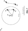
- FIG. 7 is a diagram of a device-to-device communications system 700.
- the device-to-device communications system 700 includes a plurality of wireless devices 704, 706, 708, 710.
- the device-to-device communications system 700 may overlap with a cellular communications system, such as for example, a wireless wide area network (WWAN).
- WWAN wireless wide area network
- Some of the wireless devices 704, 706, 708, 710 may communicate together in device-to-device communication using the DL/UL WWAN spectrum, some may communicate with the base station 702, and some may do both.
- the wireless devices 708, 710 are in device-to-device communication and the wireless devices 704, 706 are in device-to-device communication.
- the wireless devices 704, 706 are also communicating with the base station 702.
- the exemplary methods and apparatuses discussed infra are applicable to any of a variety of wireless device-to-device communications systems, such as for example, a wireless device-to-device communication system based on FlashLinQ, WiMedia, Bluetooth, ZigBee, or Wi-Fi based on the IEEE 802.11 standard.
- a wireless device-to-device communication system based on FlashLinQ, WiMedia, Bluetooth, ZigBee, or Wi-Fi based on the IEEE 802.11 standard.
- the exemplary methods and apparatus are discussed within the context of LTE.
- one of ordinary skill in the art would understand that the exemplary methods and apparatuses are applicable more generally to a variety of other wireless device-to-device communication systems.
- direct discovery refers to a discovery procedure involving direct peer-to-peer (or device-to-device) signaling without eNodeB signaling.
- the methods and apparatuses of the present disclosure are applicable to both intra-public land mobile network (PLMN) discovery use cases and inter-PLMN discovery use cases.
- PLMN intra-public land mobile network
- Direct discovery design previously assumed a synchronous network deployment for both time division duplex (TDD) and FDD.
- TDD time division duplex
- FDD frequency division duplex
- present disclosure provides methods for enabling reuse of existing direct discovery procedures.
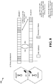
- FIG. 8 is a diagram 800 illustrating challenges related to direct discovery in asynchronous network deployments.
- FIG. 8 shows an example with two eNodeBs (eNodeB-1 and eNodeB-2).
- a first challenge (1) relates to discovery subframes not being aligned in time. Since discovery subframes are not aligned, UEs in an RRC_IDLE mode performing discovery will have to wake twice to listen to the discovery signals. This increases power consumption at the UEs since discovery is a periodic procedure.
- a second challenge (2) relates to subframe timings of the eNodeB-1 and the eNodeB-2 not being aligned. Moreover, the subframe timings may drift relative to each other with time. Referring to FIG. 8 , respective subframe timings of the eNodeB-1 and the eNodeB-2 are misaligned with each other because the eNodeB-1 and the eNodeB-2 are not synchronized. In time, the respective subframe timings may further drift apart relative to each other. The misalignment is depicted as a dashed vertical line in FIG. 8 .
- the UE may detect (and track) the timing of the neighboring eNodeB (eNodeB-2).
- a third challenge (3) relates to interference issues due to misalignment of discovery subframes.
- the misalignment of discovery subframes leads to two significant interference problems (at least in the intra-PLMN case).
- First, referring to (3a) in FIG. 8 UEs performing discovery (“discovery UEs”) impose significant interference to neighboring eNodeBs since discovery transmissions are not power controlled. This results in degraded uplink wide area network (WAN) performance at the neighboring eNodeBs.
- WAN UEs downlink wide area network
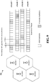
- FIG. 9 is a diagram 900 illustrating an exemplary allocation of discovery subframes across eNodeBs according to an embodiment.
- discovery resources of neighboring eNodeBs are time-adjacent to each other and non-overlapping.
- eNodeB-1 is considered a neighbor to eNodeB-4, and vice versa, although the eNodeB-1 and the eNodeB-4 are not directly adjacent to each other.
- a UE may wake once and rotate through (e.g., listen to in a sequential manner) discovery periods of a serving eNodeB and neighboring eNodeBs.
- the UE transmits discovery signals using WAN timing.
- the UE may track the timing of all neighboring eNodeBs in conjunction with the serving eNodeB.
- an eNodeB may reserve a discovery resource that is time-adjacent, non-overlapping, and within one sub frame, of a neighboring eNodeB's discovery resource.
- the time allocation of discovery resources may follow a reuse pattern across the deployment, e.g., as shown in FIG. 9 wherein the eNodeB-4 reuses discovery resources previously allocated to the eNodeB-1.
- An eNodeB may broadcast (as a part of a system information block (SIB)) to all UEs the eNodeB serves, the eNodeB's own time allocation of discovery resources as well as the time allocation of neighboring eNodeBs.
- SIB system information block
- the UE may detect and track the timing of all neighboring eNodeBs, in addition to the UE's serving eNodeB.
- the UE may listen on discovery resources for the serving eNodeB and neighboring eNodeBs (for which the timing was previously detected) by aligning the detected timing with an eNodeB corresponding to the discovery resource.
- the UE may rotate through the discovery resources according to the time pattern of allocation.
- the UE may also rotate through the multiple timing hypotheses being tracked. For example, referring to FIG. 9 , the UE may listen on the discovery resources of the eNodeB-1 and thereafter listen on the discovery resources of the eNodeB-4, which has a similar (or same) time allocation as the discovery resources of the eNodeB-1.
- An eNodeB may adjust the discovery subframe allocation to compensate for timing drifts over time. This ensures that the discovery resources remain non-overlapping and within one subframe of neighboring eNodeBs' discovery resources.
- the timing drift may be detected according to one or more of the following: 1) Detected via eNodeB-to-eNodeB signaling over a network backhaul (e.g., using time precision protocols); 2) Detected by the eNodeB via over-the-air timing synchronization signals transmitted by neighboring eNodeBs; and 3) Detected by UEs and the UEs send a timing drift report to a serving eNodeB, wherein the serving eNodeB estimates the timing drift by consolidating the reports from the UEs.
- an eNodeB may refrain from scheduling a UE performing a WAN transmission (WAN UE) in resources (e.g., subframes) that overlap/collide with the discovery resources (e.g., discovery subframes) of a neighboring eNodeB.
- the eNodeB may schedule a WAN UE in resources that overlap/collide with the discovery resources of the neighboring eNodeB if the WAN UE is in close proximity to the eNodeB.
- the eNodeB may power control the scheduled WAN UE to transmit at a power sufficient to compensate for interference from neighboring UEs performing direct discovery.
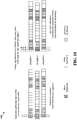
- FIG. 10 is a diagram 1000 illustrating an exemplary allocation of discovery subframes across eNodeBs according to an embodiment.
- discovery resources of all neighboring eNodeBs roughly coincide with each other, and are within one subframe of each other.
- An eNodeB may allocate one blank subframe both before and after the discovery period.
- a discovery procedure may then follow as if UEs experience out-of-network coverage.
- discovery transmissions are not performed according to eNodeB timing. Rather, the discovery transmissions are performed based on a consensus timing among UEs in the network (across eNodeBs) performing discovery.
- a UE may adjust from a eNodeB timing to a consensus discovery subframe timing during the discovery period. Timing adjustment is made possible by the blank subframe allocated before and after the discovery period.
- an eNodeB may reserve discovery resources to approximately coincide with discovery resources of neighboring eNodeBs.
- the eNodeB may further ensure that the reserved discovery resources are within one subframe of the discovery resources of the neighboring eNodeBs.
- the eNodeB may reserve one subframe before and after the discovery resources (discovery subframes) as a blank subframe, wherein the blank subframe is a subframe where no WAN operation or discovery operation occurs.
- a UE participating in discovery may time align the UE's discovery subframes with discovery subframes of other peer UEs by performing peer-to-peer timing synchronization with the other peer UEs.
- the time-aligned discovery subframes may be referred to as a consensus discovery timing.
- UEs may adjust from a respective WAN timing to the consensus discovery timing when transitioning from respective WAN resources to the discovery resources.
- the UEs may transmit and receive the discovery signals using the discovery timing.
- the eNodeB of FIG. 10 may adjust the discovery subframe allocation to compensate for timing drifts over time. This ensures that the discovery resources of all neighboring eNodeBs roughly coincide with each other, and are within one subframe of each other.
- the timing drift may be detected according to one or more of the following: 1) eNodeB-to-eNodeB signaling over a network backhaul (e.g., using time precision protocols); 2) Detected by eNodeB via over-the-air timing synchronization signals transmitted by neighboring eNodeBs; and 3) Detected by UEs and the UEs send a timing drift report to a serving eNodeB, wherein the serving eNodeB estimates the timing drift by consolidating the reports from the UEs.
- continual eNodeB coordination is needed with respect to adjusting the discovery subframe allocation to compensate for timing drifts.
- the present disclosure also provides for an operation that does not require continual eNodeB coordination.
- eNodeBs may freely and independently allocate discovery subframes.
- an eNodeB may broadcast (e.g., as a part of a system information block (SIB)) to all UEs the eNodeB serves, the eNodeB's own time allocation of discovery resources as well as the time allocation of neighboring eNodeBs.
- SIB system information block
- a UE may track the discovery resources/subframes (timing) of all neighboring eNodeBs in addition to the UE's serving eNodeB.
- the timing is derived from downlink synchronization signals broadcast by a neighboring eNodeB.
- the timing is derived from discovery transmissions from UEs that belong to the neighboring eNodeB. The UE may listen on the discovery resources of the serving eNodeB and the neighboring eNodeBs for which the timing was derived by aligning the timing with the eNodeB that owns the discovery resource.
- the operations described above assumed that the eNodeBs belong to the same public land mobile network (PLMN) (intra-PLMN discovery).
- PLMN public land mobile network
- the present disclosure may be extended to inter-PLMN discovery.
- uplink and downlink spectrums may be different, thus interference between WAN and discovery operations may occur.
- neighboreNodeBs may be used in the present disclosure, the eNodeBs may be co-located for inter-PLMN.
- an eNodeB may broadcast (as a part of a system information block (SIB)), a spectrum used by neighboring eNodeBs that belong to a PLMN different from the PLMN of the eNodeB.
- SIB system information block
- a UE may tune to a downlink spectrum of a neighboring eNodeB while listening for timing synchronization from the eNodeB.
- the UE may tune to an uplink spectrum of the neighboring eNodeB while listening for discovery transmissions from UEs associated with the eNodeB.
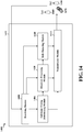
- FIG. 11 is a flow chart 1100 of a method of wireless communication.
- the method may be performed by a UE.
- the UE receives information from a serving base station and at least one neighboring base station.
- the information may indicate a time allocation of discovery resources allocated by each of the serving base station and the at least one neighboring base station for performing direct discovery.
- the discovery resources corresponding to a base station may be time-adjacent, non-overlapping, and within one sub frame of the discovery resources corresponding to a neighboring base station. Additionally, or alternatively, the time allocation of the discovery resources corresponding to a base station may be the same as the time allocation of the discovery resources corresponding to a neighboring base station.
- the UE determines a subframe timing of the serving base station and the at least one neighboring base station.
- the subframe timing may be determined based on downlink synchronization signals broadcast by the at least one neighboring base station.
- the UE may tune to a downlink frequency spectrum of the at least one neighboring base station when determining the subframe timing of the at least one neighboring base station.
- the subframe timing may be determined based on a transmission from one or more UEs performing direct discovery, wherein the one or more UEs are served by the at least one neighboring base station.
- the UE performs direct discovery using the time allocation of the discovery resources allocated by each of the serving base station and the at least one neighboring base station based on a determined subframe timing of the serving base station or a neighboring base station corresponding to the discovery resources.
- the UE may tune to an uplink frequency spectrum of the at least one neighboring base station when performing the direct discovery for one or more UEs served by the at least one neighboring base station.
- the UE may wake once to perform the direct discovery using each of the allocated discovery resources in a sequential manner according to the time allocation of each of the allocated discovery resources. Additionally or alternatively, the UE may wake once to perform the direct discovery using each of the allocated discovery resources having the same time allocation in a sequential manner.
- the UE detects a timing drift between the time allocation of the discovery resources corresponding to a base station and the time allocation of the discovery resources corresponding to a neighboring base station. Thereafter, the UE reports the timing drift to the serving base station.
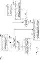
- FIG. 12 is a flow chart 1200 of a method of wireless communication.
- the method may be performed by a base station or eNodeB (eNB).
- the base station reserves a time allocation of discovery resources for use by at least one UE to perform direct discovery.
- the discovery resources corresponding to the base station may be time-adjacent, non-overlapping, and within one subframe of discovery resources corresponding to a neighboring base station.
- the discovery resources corresponding to the base station may coincide with discovery resources corresponding to at least one neighboring base station and may be within one subframe of the discovery resources corresponding to the at least one neighboring base station.
- a blank subframe may precede and follow the time allocation of the discovery resources.
- the time allocation of the discovery resources corresponding to the base station may also be the same as the time allocation of the discovery resources corresponding to a neighboring base station.
- the base station sends information indicating the time allocation of the discovery resources to the at least one UE served by the base station.
- the information may further indicate the time allocation of discovery resources allocated by at least one neighboring base station for performing direct discovery.
- the information may also indicate a frequency spectrum used by the at least one neighboring base station belonging to a public land mobile network (PLMN) different from a PLMN of the base station.
- PLMN public land mobile network
- the base station may detect a timing drift between the time allocation of the discovery resources corresponding to the base station and the time allocation of the discovery resources corresponding to a neighboring base station.
- the timing drift may be detected by receiving timing information from a neighboring base station via a network backhaul, receiving a synchronization signal from the neighboring base station via an over-the-air signal, and/or receiving a timing drift report from a UE served by the base station.
- the base station may adjust the time allocation of the discovery resources corresponding to the base station based on the detected timing drift.
- the base station may refrain from scheduling a UE performing a wide area network (WAN) operation in resources that overlap with the discovery resources allocated by the at least one neighboring base station.
- the base station may first determine if a UE is in close proximity to the base station. Based on a negative result, the base station may proceed to step 1210 and refrain from scheduling the UE.
- WAN wide area network
- the base station may schedule the UE performing the WAN operation in the resources that overlap with the discovery resources allocated by the at least one neighboring base station.
- the base station may power control the scheduled UE to transmit at a power sufficient to compensate for interference from UEs performing direct discovery.
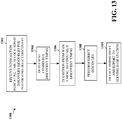
- FIG. 13 is a flow chart 1300 of a method of wireless communication.
- the method may be performed by a UE.
- the UE receives information from a serving base station and at least one neighboring base station.
- the information may indicate a time allocation of discovery resources allocated by each of the serving base station and the at least one neighboring base station for performing direct discovery.
- the discovery resources corresponding to the serving base station may coincide with discovery resources corresponding to at least one neighboring base station and may be within one subframe of the discovery resources corresponding to the at least one neighboring base station.
- a blank subframe may precede and follow the time allocation of the discovery resources.
- the UE determines a consensus discovery timing by synchronizing the time allocation of the discovery resources indicated by the received information with a time allocation of discovery resources of at least one other UE performing direct discovery.
- the UE may transition from a timing for performing a WAN operation to the consensus discovery timing when transitioning from a WAN resource to the discovery resources.
- the UE performs the direct discovery based on the consensus discovery timing.
- the UE may wake once according to the consensus discovery timing to perform the direct discovery using the discovery resources corresponding to the serving base station and the at least one neighboring base station.
- the UE may tune to an uplink frequency spectrum of the at least one neighboring base station when performing the direct discovery for at least one UE served by the at least one neighboring base station.
- the UE may tune to a downlink frequency spectrum of the at least one neighboring base station when determining a subframe timing of the at least one neighboring base station.
- the UE detects a timing drift between the time allocation of the discovery resources corresponding to a base station and the time allocation of the discovery resources corresponding to a neighboring base station. Thereafter, the UE reports the timing drift to the serving base station.
- FIG. 14 is a conceptual data flow diagram 1400 illustrating the data flow between different modules/means/components in an exemplary apparatus 1402.
- the apparatus may be a UE.
- the apparatus includes a receiving module 1404, a subframe timing determining module 1406, a discovery processing module 1408, a drift detecting module 1410, and a transmission module 1412.
- the receiving module 1404 receives information from a serving base station 1450 and at least one neighboring base station 1460.
- the information may indicate a time allocation of discovery resources allocated by each of the serving base station 1450 and the at least one neighboring base station 1460 for performing direct discovery.
- the discovery resources corresponding to a base station may be time-adjacent, non-overlapping, and within one subframe of the discovery resources corresponding to a neighboring base station. Additionally, or alternatively, the time allocation of the discovery resources corresponding to a base station may be the same as the time allocation of the discovery resources corresponding to a neighboring base station.
- the subframe timing determining module 1406 determines a subframe timing of the serving base station 1450 and the at least one neighboring base station 1460.
- the subframe timing may be determined based on downlink synchronization signals broadcast by the at least one neighboring base station 1460.
- the subframe timing determining module 1406 may tune to a downlink frequency spectrum of the at least one neighboring base station 1460 when determining the subframe timing of the at least one neighboring base station 1460.
- the subframe timing may be determined based on a transmission from one or more UEs (e.g., UE 1470) performing direct discovery, wherein the one or more UEs are served by the at least one neighboring base station 1460.
- the discovery processing module 1408 performs direct discovery using the time allocation of the discovery resources allocated by each of the serving base station 1450 and the at least one neighboring base station 1460 based on a determined subframe timing of the serving base station 1450 or a neighboring base station 1460 corresponding to the discovery resources.
- the discovery processing module 1408 may tune to an uplink frequency spectrum of the at least one neighboring base station 1460 when performing the direct discovery for one or more UEs (e.g., UE 1470) served by the at least one neighboring base station 1460.
- the apparatus 1402 may wake once to perform the direct discovery using each of the allocated discovery resources in a sequential manner according to the time allocation of each of the allocated discovery resources. Additionally or alternatively, the apparatus 1402 may wake once to perform the direct discovery using each of the allocated discovery resources having the same time allocation in a sequential manner.
- the drift detecting module 1410 detects a timing drift between the time allocation of the discovery resources corresponding to a base station and the time allocation of the discovery resources corresponding to a neighboring base station. Thereafter, the drift detecting module 1410 reports the timing drift to the serving base station 1450 via the transmission module 1412.
- the discovery resources corresponding to the serving base station 1450 may coincide with discovery resources corresponding to at least one neighboring base station 1460 and may be within one subframe of the discovery resources corresponding to the at least one neighboring base station 1460. A blank subframe may precede and follow the time allocation of the discovery resources.
- the discovery processing module 1408 may determine a consensus discovery timing by synchronizing the time allocation of the discovery resources indicated by the received information with a time allocation of discovery resources of at least one other UE (e.g., UE 1470) performing direct discovery.
- the discovery processing module 1408 may transition the apparatus 1402 from a timing for performing a WAN operation to the consensus discovery timing when the apparatus 1402 transitions from a WAN resource to the discovery resources.
- the discovery processing module 1408 may perform the direct discovery based on the consensus discovery timing.
- the apparatus 1402 may wake once according to the consensus discovery timing to perform the direct discovery using the discovery resources corresponding to the serving base station 1450 and the at least one neighboring base station 1460.
- the discovery processing module 1408 may tune to an uplink frequency spectrum of the at least one neighboring base station 1460 when performing the direct discovery for at least one UE (e.g., UE 1470) served by the at least one neighboring base station 1460.
- the subframe timing determining module 1406 may tune to a downlink frequency spectrum of the at least one neighboring base station 1460 when determining a sub frame timing of the at least one neighboring base station 1460.
- the apparatus may include additional modules that perform each of the steps of the algorithm in the aforementioned flow charts of FIGs. 11 and 13 . As such, each step in the aforementioned flow charts of FIGs. 11 and 13 may be performed by a module and the apparatus may include one or more of those modules.
- the modules may be one or more hardware components specifically configured to carry out the stated processes/algorithm, implemented by a processor configured to perform the stated processes/algorithm, stored within a computer-readable medium for implementation by a processor, or some combination thereof.
- FIG. 15 is a conceptual data flow diagram 1500 illustrating the data flow between different modules/means/components in an exemplary apparatus 1502.
- the apparatus may be a base station or eNodeB (eNB).
- the apparatus 1502 includes a receiving module 1504, a WAN processing module 1506, a discovery processing module 1508, a drift detecting module 1510, a power control module 1512, and a transmission module 1514.
- the discovery processing module 1508 reserves a time allocation of discovery resources for use by at least one UE (e.g., UE 1570) to perform direct discovery.
- the discovery resources corresponding to the base station 1502 may be time-adjacent, non-overlapping, and within one subframe of discovery resources corresponding to a neighboring base station 1550.
- the discovery resources corresponding to the base station 1502 may coincide with discovery resources corresponding to at least one neighboring base station 1550 and may be within one subframe of the discovery resources corresponding to the at least one neighboring base station 1550.
- a blank subframe may precede and follow the time allocation of the discovery resources.
- the time allocation of the discovery resources corresponding to the base station 1502 may also be the same as the time allocation of the discovery resources corresponding to a neighboring base station 1550.
- the discovery processing module 1508 sends (via the transmission module 1514) information indicating the time allocation of the discovery resources to the at least one UE (e.g., UE 1570) served by the base station 1502.
- the information may further indicate the time allocation of discovery resources allocated by at least one neighboring base station 1550 for performing direct discovery.
- the information may also indicate a frequency spectrum used by the at least one neighboring base station 1550 belonging to a public land mobile network (PLMN) different from a PLMN of the base station 1502.
- PLMN public land mobile network
- the drift detecting module 1510 may detect a timing drift between the time allocation of the discovery resources corresponding to the base station 1502 and the time allocation of the discovery resources corresponding to a neighboring base station 1550.
- the timing drift may be detected by receiving timing information from a neighboring base station 1550 via a network backhaul, receiving a synchronization signal from the neighboring base station 1550 via an over-the-air signal, and/or receiving a timing drift report from a UE 1570 served by the base station.
- the discovery processing module 1508 may adjust the time allocation of the discovery resources corresponding to the base station 1502 based on the detected timing drift.
- the WAN processing module 1506 may refrain from scheduling a UE performing a wide area network (WAN) operation in resources that overlap with the discovery resources allocated by the at least one neighboring base station 1550. Alternatively, the WAN processing module 1506 may first determine if a UE is in close proximity to the base station 1502. Based on a negative result, the WAN processing module 1506 may refrain from scheduling the UE.
- WAN wide area network
- the WAN processing module 1506 may schedule the UE performing the WAN operation in the resources that overlap with the discovery resources allocated by the at least one neighboring base station 1550.
- the power control module 1512 may power control the scheduled UE to transmit at a power sufficient to compensate for interference from UEs performing direct discovery.
- the apparatus may include additional modules that perform each of the steps of the algorithm in the aforementioned flow chart of FIG. 12 .
- each step in the aforementioned flow chart of FIG. 12 may be performed by a module and the apparatus may include one or more of those modules.
- the modules may be one or more hardware components specifically configured to carry out the stated processes/algorithm, implemented by a processor configured to perform the stated processes/algorithm, stored within a computer-readable medium for implementation by a processor, or some combination thereof.
- FIG. 16 is a diagram 1600 illustrating an example of a hardware implementation for an apparatus 1402' employing a processing system 1614.
- the processing system 1614 may be implemented with a bus architecture, represented generally by the bus 1624.
- the bus 1624 may include any number of interconnecting buses and bridges depending on the specific application of the processing system 1614 and the overall design constraints.
- the bus 1624 links together various circuits including one or more processors and/or hardware modules, represented by the processor 1604, the modules 1404, 1406, 1408, 1410, 1412, and the computer-readable medium / memory 1606.
- the bus 1624 may also link various other circuits such as timing sources, peripherals, voltage regulators, and power management circuits, which are well known in the art, and therefore, will not be described any further.
- the processing system 1614 may be coupled to a transceiver 1610.
- the transceiver 1610 is coupled to one or more antennas 1620.
- the transceiver 1610 provides a means for communicating with various other apparatus over a transmission medium.
- the transceiver 1610 receives a signal from the one or more antennas 1620, extracts information from the received signal, and provides the extracted information to the processing system 1614, specifically the receiving module 1404.
- the transceiver 1610 receives information from the processing system 1614, specifically the transmission module 1414, and based on the received information, generates a signal to be applied to the one or more antennas 1620.
- the processing system 1614 includes a processor 1604 coupled to a computer-readable medium / memory 1606.
- the processor 1604 is responsible for general processing, including the execution of software stored on the computer-readable medium / memory 1606.
- the software when executed by the processor 1604, causes the processing system 1614 to perform the various functions described supra for any particular apparatus.
- the computer-readable medium / memory 1606 may also be used for storing data that is manipulated by the processor 1604 when executing software.
- the processing system further includes at least one of the modules 1404, 1406, 1408, 1410, and 1412.
- the modules may be software modules running in the processor 1604, resident/stored in the computer readable medium / memory 1606, one or more hardware modules coupled to the processor 1604, or some combination thereof.
- the processing system 1614 may be a component of the UE 650 and may include the memory 660 and/or at least one of the TX processor 668, the RX processor 656, and the controller/processor 659.
- the apparatus 1402/1402' for wireless communication includes means for means for receiving information from a serving base station and at least one neighboring base station, the information indicating a time allocation of discovery resources allocated by each of the serving base station and the at least one neighboring base station for performing direct discovery, means for determining a subframe timing of the serving base station and the at least one neighboring base station, means for performing direct discovery using the time allocation of the discovery resources allocated by each of the serving base station and the at least one neighboring base station based on a determined subframe timing of the serving base station or a neighboring base station corresponding to the discovery resources, means for detecting a timing drift between the time allocation of the discovery resources corresponding to a base station and the time allocation of the discovery resources corresponding to a neighboring base station, means for reporting the timing drift to the serving base station, means for determining a consensus discovery timing by synchronizing the time allocation of the discovery resources indicated by the received information with a time allocation of discovery resources of at least one other UE performing direct discovery, means for performing the direct discovery
- the aforementioned means may be one or more of the aforementioned modules of the apparatus 1402 and/or the processing system 1614 of the apparatus 1402' configured to perform the functions recited by the aforementioned means.
- the processing system 1614 may include the TX Processor 668, the RX Processor 656, and the controller/processor 659.
- the aforementioned means may be the TX Processor 668, the RX Processor 656, and the controller/processor 659 configured to perform the functions recited by the aforementioned means.
- FIG. 17 is a diagram 1700 illustrating an example of a hardware implementation for an apparatus 1502' employing a processing system 1714.
- the processing system 1714 may be implemented with a bus architecture, represented generally by the bus 1724.
- the bus 1724 may include any number of interconnecting buses and bridges depending on the specific application of the processing system 1714 and the overall design constraints.
- the bus 1724 links together various circuits including one or more processors and/or hardware modules, represented by the processor 1704, the modules 1504, 1506, 1508, 1510, 1512, 1514 and the computer-readable medium / memory 1706.
- the bus 1724 may also link various other circuits such as timing sources, peripherals, voltage regulators, and power management circuits, which are well known in the art, and therefore, will not be described any further.
- the processing system 1714 may be coupled to a transceiver 1710.
- the transceiver 1710 is coupled to one or more antennas 1720.
- the transceiver 1710 provides a means for communicating with various other apparatus over a transmission medium.
- the transceiver 1710 receives a signal from the one or more antennas 1720, extracts information from the received signal, and provides the extracted information to the processing system 1714, specifically the receiving module 1504.
- the transceiver 1710 receives information from the processing system 1714, specifically the transmission module 1514, and based on the received information, generates a signal to be applied to the one or more antennas 1720.
- the processing system 1714 includes a processor 1704 coupled to a computer-readable medium / memory 1706.
- the processor 1704 is responsible for general processing, including the execution of software stored on the computer-readable medium / memory 1706.
- the software when executed by the processor 1704, causes the processing system 1714 to perform the various functions described supra for any particular apparatus.
- the computer-readable medium / memory 1706 may also be used for storing data that is manipulated by the processor 1704 when executing software.
- the processing system further includes at least one of the modules 1504, 1506, 1508, 1510, 1512, and 1514.
- the modules may be software modules running in the processor 1704, resident/stored in the computer readable medium / memory 1706, one or more hardware modules coupled to the processor 1704, or some combination thereof.
- the processing system 1714 may be a component of the eNB 610 and may include the memory 676 and/or at least one of the TX processor 616, the RX processor 670, and the controller/processor 675.
- the apparatus 1502/1502' for wireless communication includes means for reserving a time allocation of discovery resources for performing direct discovery, means for sending information indicating the time allocation of the discovery resources to at least one user equipment (UE) served by the base station, wherein the information further indicates the time allocation of discovery resources allocated by at least one neighboring base station for performing direct discovery, means for detecting a timing drift between the time allocation of the discovery resources corresponding to the base station and the time allocation of the discovery resources corresponding to a neighboring base station, means for adjusting the time allocation of the discovery resources corresponding to the base station based on the detected timing drift, means for refraining from scheduling a UE performing a wide area network (WAN) operation in resources that overlap with the discovery resources allocated by the at least one neighboring base station, means for scheduling a UE performing a wide area network (WAN) operation in resources that overlap with the discovery resources allocated by the at least one neighboring base station when the UE is in close proximity to the base station, means for power controlling the scheduled UE to transmit at a power sufficient to
- the aforementioned means may be one or more of the aforementioned modules of the apparatus 1502 and/or the processing system 1714 of the apparatus 1502' configured to perform the functions recited by the aforementioned means.
- the processing system 1714 may include the TX Processor 616, the RX Processor 670, and the controller/processor 675.
- the aforementioned means may be the TX Processor 616, the RX Processor 670, and the controller/processor 675 configured to perform the functions recited by the aforementioned means.
- Combinations such as "at least one of A, B, or C,” “at least one of A, B, and C,” and “A, B, C, or any combination thereof' include any combination of A, B, and/or C, and may include multiples of A, multiples of B, or multiples of C.
- combinations such as “at least one of A, B, or C,” “at least one of A, B, and C,” and “A, B, C, or any combination thereof' may be A only, B only, C only, A and B, A and C, B and C, or A and B and C, where any such combinations may contain one or more member or members of A, B, or C.
- No claim element is to be construed as a means plus function unless the element is expressly recited using the phrase "means for.”
Description
- The present disclosure relates generally to communication systems, and more particularly, to enabling direct discovery among user equipments (UEs) in an asynchronous frequency division duplex (FDD) network deployment where eNodeBs are not synchronized with each other.
- Wireless communication systems are widely deployed to provide various telecommunication services such as telephony, video, data, messaging, and broadcasts. Typical wireless communication systems may employ multiple-access technologies capable of supporting communication with multiple users by sharing available system resources (e.g., bandwidth, transmit power). Examples of such multiple-access technologies include code division multiple access (CDMA) systems, time division multiple access (TDMA) systems, frequency division multiple access (FDMA) systems, orthogonal frequency division multiple access (OFDMA) systems, single-carrier frequency division multiple access (SC-FDMA) systems, and time division synchronous code division multiple access (TD-SCDMA) systems.
- These multiple access technologies have been adopted in various telecommunication standards to provide a common protocol that enables different wireless devices to communicate on a municipal, national, regional, and even global level. An example of an emerging telecommunication standard is Long Term Evolution (LTE). LTE is a set of enhancements to the Universal Mobile Telecommunications System (UMTS) mobile standard promulgated by Third Generation Partnership Project (3GPP). It is designed to better support mobile broadband Internet access by improving spectral efficiency, lowering costs, improving services, making use of new spectrum, and better integrating with other open standards using OFDMA on the downlink (DL), SC-FDMA on the uplink (UL), and multiple-input multiple-output (MIMO) antenna technology. However, as the demand for mobile broadband access continues to increase, there exists a need for further improvements in LTE technology. Preferably, these improvements should be applicable to other multi-access technologies and the telecommunication standards that employ these technologies. Qualcomm Incorporated: "Techniques for D2D Discovery", 3GPP Draft, TSG-RAN WG1 #73, R1-132503, Fukuoka, Japan discusses techniques and design principles for performing device to device discovery.
- In accordance with the present invention, there are provided a method of wireless communication at a user equipment as recited by
claim 1, a method of wireless communication at a base station as recited byclaim 9, an apparatus for wireless communication at a user equipment as recited by claim 13, and an apparatus for wireless communication at a base station as recited by claim 15. The embodiments and/or examples of the following description which are not covered by the appended claims are considered as not being part of the present invention. In an aspect of the disclosure, a method, a computer program product, and an apparatus are provided. The apparatus receives information from a serving base station and at least one neighboring base station, the information indicating a time allocation of discovery resources allocated by each of the serving base station and the at least one neighboring base station for performing direct discovery, determines a subframe timing of the serving base station and the at least one neighboring base station, and performs direct discovery using the time allocation of the discovery resources allocated by each of the serving base station and the at least one neighboring base station based on a determined subframe timing of the serving base station or a neighboring base station corresponding to the discovery resources. - In another aspect of the disclosure, the apparatus reserves a time allocation of discovery resources for performing direct discovery, and sends information indicating the time allocation of the discovery resources to at least one user equipment (UE) served by the base station, wherein the information further indicates the time allocation of discovery resources allocated by at least one neighboring base station for performing direct discovery.
- In a further aspect of the disclosure, the apparatus receives information from a serving base station and at least one neighboring base station, the information indicating a time allocation of discovery resources allocated by each of the serving base station and the at least one neighboring base station for performing direct discovery, determines a consensus discovery timing by synchronizing the time allocation of the discovery resources indicated by the received information with a time allocation of discovery resources of at least one other UE performing direct discovery, and performs the direct discovery based on the consensus discovery timing.
- In yet another aspect of the disclosure, the apparatus reserves a time allocation of discovery resources for performing direct discovery, and sends information indicating the time allocation of the discovery resources to at least one user equipment (UE) served by the base station, wherein the discovery resources corresponding to the base station coincide with discovery resources corresponding to at least one neighboring base station, and are within one subframe of the discovery resources corresponding to the at least one neighboring base station, wherein a blank subframe precedes and follows the time allocation of the discovery resources.
-
-
FIG. 1 is a diagram illustrating an example of a network architecture. -
FIG. 2 is a diagram illustrating an example of an access network. -
FIG. 3 is a diagram illustrating an example of a DL frame structure in LTE. -
FIG. 4 is a diagram illustrating an example of an UL frame structure in LTE. -
FIG. 5 is a diagram illustrating an example of a radio protocol architecture for the user and control planes. -
FIG. 6 is a diagram illustrating an example of an evolved Node B and user equipment in an access network. -
FIG. 7 is a diagram of a device-to-device communications system. -
FIG. 8 is a diagram illustrating challenges related to direct discovery in asynchronous network deployments. -
FIG. 9 is a diagram illustrating an exemplary allocation of discovery subframes across eNodeBs according to an embodiment. -
FIG. 10 is a diagram illustrating an exemplary allocation of discovery subframes across eNodeBs according to an embodiment. -
FIG. 11 is a flow chart of a method of wireless communication. -
FIG. 12 is a flow chart of a method of wireless communication. -
FIG. 13 is a flow chart of a method of wireless communication. -
FIG. 14 is a conceptual data flow diagram illustrating the data flow between different modules/means/components in an exemplary apparatus. -
FIG. 15 is a conceptual data flow diagram illustrating the data flow between different modules/means/components in an exemplary apparatus. -
FIG. 16 is a diagram illustrating an example of a hardware implementation for an apparatus employing a processing system. -
FIG. 17 is a diagram illustrating an example of a hardware implementation for an apparatus employing a processing system. - The detailed description set forth below in connection with the appended drawings is intended as a description of various configurations and is not intended to represent the only configurations in which the concepts described herein may be practiced. The detailed description includes specific details for the purpose of providing a thorough understanding of various concepts. However, it will be apparent to those skilled in the art that these concepts may be practiced without these specific details. In some instances, well known structures and components are shown in block diagram form in order to avoid obscuring such concepts.
- Several aspects of telecommunication systems will now be presented with reference to various apparatus and methods. These apparatus and methods will be described in the following detailed description and illustrated in the accompanying drawings by various blocks, modules, components, circuits, steps, processes, algorithms, etc. (collectively referred to as "elements"). These elements may be implemented using electronic hardware, computer software, or any combination thereof. Whether such elements are implemented as hardware or software depends upon the particular application and design constraints imposed on the overall system.
- By way of example, an element, or any portion of an element, or any combination of elements may be implemented with a "processing system" that includes one or more processors. Examples of processors include microprocessors, microcontrollers, digital signal processors (DSPs), field programmable gate arrays (FPGAs), programmable logic devices (PLDs), state machines, gated logic, discrete hardware circuits, and other suitable hardware configured to perform the various functionality described throughout this disclosure. One or more processors in the processing system may execute software. Software shall be construed broadly to mean instructions, instruction sets, code, code segments, program code, programs, subprograms, software modules, applications, software applications, software packages, routines, subroutines, objects, executables, threads of execution, procedures, functions, etc., whether referred to as software, firmware, middleware, microcode, hardware description language, or otherwise.
- Accordingly, in one or more exemplary embodiments, the functions described may be implemented in hardware, software, firmware, or any combination thereof. If implemented in software, the functions may be stored on or encoded as one or more instructions or code on a computer-readable medium. Computer-readable media includes computer storage media. Storage media may be any available media that can be accessed by a computer. By way of example, and not limitation, such computer-readable media can comprise a random-access memory (RAM), a read-only memory (ROM), an electrically erasable programmable ROM (EEPROM), compact disk ROM (CD-ROM) or other optical disk storage, magnetic disk storage or other magnetic storage devices, or any other medium that can be used to carry or store desired program code in the form of instructions or data structures and that can be accessed by a computer. Disk and disc, as used herein, includes CD, laser disc, optical disc, digital versatile disc (DVD), and floppy disk where disks usually reproduce data magnetically, while discs reproduce data optically with lasers. Combinations of the above should also be included within the scope of computer-readable media.
-
FIG. 1 is a diagram illustrating anLTE network architecture 100. TheLTE network architecture 100 may be referred to as an Evolved Packet System (EPS) 100. The EPS 100 may include one or more user equipment (UE) 102, an Evolved UMTS Terrestrial Radio Access Network (E-UTRAN) 104, an Evolved Packet Core (EPC) 110, a Home Subscriber Server (HSS) 120, and an Operator's Internet Protocol (IP)Services 122. The EPS can interconnect with other access networks, but for simplicity those entities/interfaces are not shown. As shown, the EPS provides packet-switched services, however, as those skilled in the art will readily appreciate, the various concepts presented throughout this disclosure may be extended to networks providing circuit-switched services. - The E-UTRAN includes the evolved Node B (eNB) 106 and
other eNBs 108. TheeNB 106 provides user and control planes protocol terminations toward theUE 102. TheeNB 106 may be connected to theother eNBs 108 via a backhaul (e.g., an X2 interface). TheeNB 106 may also be referred to as a base station, a Node B, an access point, a base transceiver station, a radio base station, a radio transceiver, a transceiver function, a basic service set (BSS), an extended service set (ESS), or some other suitable terminology. TheeNB 106 provides an access point to theEPC 110 for aUE 102. Examples ofUEs 102 include a cellular phone, a smart phone, a session initiation protocol (SIP) phone, a laptop, a personal digital assistant (PDA), a satellite radio, a global positioning system, a multimedia device, a video device, a digital audio player (e.g., MP3 player), a camera, a game console, a tablet, or any other similar functioning device. TheUE 102 may also be referred to by those skilled in the art as a mobile station, a subscriber station, a mobile unit, a subscriber unit, a wireless unit, a remote unit, a mobile device, a wireless device, a wireless communications device, a remote device, a mobile subscriber station, an access terminal, a mobile terminal, a wireless terminal, a remote terminal, a handset, a user agent, a mobile client, a client, or some other suitable terminology. - The
eNB 106 is connected to theEPC 110. TheEPC 110 may include a Mobility Management Entity (MME) 112,other MMEs 114, aServing Gateway 116, a Multimedia Broadcast Multicast Service (MBMS)Gateway 124, a Broadcast Multicast Service Center (BM-SC) 126, and a Packet Data Network (PDN)Gateway 118. TheMME 112 is the control node that processes the signaling between theUE 102 and theEPC 110. Generally, theMME 112 provides bearer and connection management. All user IP packets are transferred through theServing Gateway 116, which itself is connected to thePDN Gateway 118. ThePDN Gateway 118 provides UE IP address allocation as well as other functions. ThePDN Gateway 118 is connected to the Operator's IP Services 122. The Operator'sIP Services 122 may include the Internet, an intranet, an IP Multimedia Subsystem (IMS), and a PS Streaming Service (PSS). The BM-SC 126 may provide functions for MBMS user service provisioning and delivery. The BM-SC 126 may serve as an entry point for content provider MBMS transmission, may be used to authorize and initiate MBMS Bearer Services within a PLMN, and may be used to schedule and deliver MBMS transmissions. TheMBMS Gateway 124 may be used to distribute MBMS traffic to the eNBs (e.g., 106, 108) belonging to a Multicast Broadcast Single Frequency Network (MBSFN) area broadcasting a particular service, and may be responsible for session management (start/stop) and for collecting eMBMS related charging information. -
FIG. 2 is a diagram illustrating an example of anaccess network 200 in an LTE network architecture. In this example, theaccess network 200 is divided into a number of cellular regions (cells) 202. One or more lowerpower class eNBs 208 may havecellular regions 210 that overlap with one or more of thecells 202. The lowerpower class eNB 208 may be a femto cell (e.g., home eNB (HeNB)), pico cell, micro cell, or remote radio head (RRH). Themacro eNBs 204 are each assigned to arespective cell 202 and are configured to provide an access point to theEPC 110 for all theUEs 206 in thecells 202. There is no centralized controller in this example of anaccess network 200, but a centralized controller may be used in alternative configurations. TheeNBs 204 are responsible for all radio related functions including radio bearer control, admission control, mobility control, scheduling, security, and connectivity to theserving gateway 116. An eNB may support one or multiple (e.g., three) cells (also referred to as a sector). The term "cell" can refer to the smallest coverage area of an eNB and/or an eNB subsystem serving are particular coverage area. Further, the terms "eNB," "base station," and "cell" may be used interchangeably herein. - The modulation and multiple access scheme employed by the
access network 200 may vary depending on the particular telecommunications standard being deployed. In LTE applications, OFDM is used on the DL and SC-FDMA is used on the UL to support both frequency division duplex (FDD) and time division duplex (TDD). As those skilled in the art will readily appreciate from the detailed description to follow, the various concepts presented herein are well suited for LTE applications. However, these concepts may be readily extended to other telecommunication standards employing other modulation and multiple access techniques. By way of example, these concepts may be extended to Evolution-Data Optimized (EV-DO) or Ultra Mobile Broadband (UMB). EV-DO and UMB are air interface standards promulgated by the 3rd Generation Partnership Project 2 (3GPP2) as part of the CDMA2000 family of standards and employs CDMA to provide broadband Internet access to mobile stations. These concepts may also be extended to Universal Terrestrial Radio Access (UTRA) employing Wideband-CDMA (W-CDMA) and other variants of CDMA, such as TD-SCDMA; Global System for Mobile Communications (GSM) employing TDMA; and Evolved UTRA (E-UTRA), IEEE 802.11 (Wi-Fi), IEEE 802.16 (WiMAX), IEEE 802.20, and Flash-OFDM employing OFDMA. UTRA, E-UTRA, UMTS, LTE and GSM are described in documents from the 3GPP organization. CDMA2000 and UMB are described in documents from the 3GPP2 organization. The actual wireless communication standard and the multiple access technology employed will depend on the specific application and the overall design constraints imposed on the system. - The
eNBs 204 may have multiple antennas supporting MIMO technology. The use of MIMO technology enables theeNBs 204 to exploit the spatial domain to support spatial multiplexing, beamforming, and transmit diversity. Spatial multiplexing may be used to transmit different streams of data simultaneously on the same frequency. The data streams may be transmitted to asingle UE 206 to increase the data rate or tomultiple UEs 206 to increase the overall system capacity. This is achieved by spatially precoding each data stream (i.e., applying a scaling of an amplitude and a phase) and then transmitting each spatially precoded stream through multiple transmit antennas on the DL. The spatially precoded data streams arrive at the UE(s) 206 with different spatial signatures, which enables each of the UE(s) 206 to recover the one or more data streams destined for thatUE 206. On the UL, eachUE 206 transmits a spatially precoded data stream, which enables theeNB 204 to identify the source of each spatially precoded data stream. - Spatial multiplexing is generally used when channel conditions are good. When channel conditions are less favorable, beamforming may be used to focus the transmission energy in one or more directions. This may be achieved by spatially precoding the data for transmission through multiple antennas. To achieve good coverage at the edges of the cell, a single stream beamforming transmission may be used in combination with transmit diversity.
- In the detailed description that follows, various aspects of an access network will be described with reference to a MIMO system supporting OFDM on the DL. OFDM is a spread-spectrum technique that modulates data over a number of subcarriers within an OFDM symbol. The subcarriers are spaced apart at precise frequencies. The spacing provides "orthogonality" that enables a receiver to recover the data from the subcarriers. In the time domain, a guard interval (e.g., cyclic prefix) may be added to each OFDM symbol to combat inter-OFDM-symbol interference. The UL may use SC-FDMA in the form of a DFT-spread OFDM signal to compensate for high peak-to-average power ratio (PAPR).
-
FIG. 3 is a diagram 300 illustrating an example of a DL frame structure in LTE. A frame (10 ms) may be divided into 10 equally sized subframes. Each subframe may include two consecutive time slots. A resource grid may be used to represent two time slots, each time slot including a resource block. The resource grid is divided into multiple resource elements. In LTE, a resource block contains 12 consecutive subcarriers in the frequency domain and, for a normal cyclic prefix in each OFDM symbol, 7 consecutive OFDM symbols in the time domain, or 84 resource elements. For an extended cyclic prefix, a resource block contains 6 consecutive OFDM symbols in the time domain and has 72 resource elements. Some of the resource elements, indicated asR RS 304 are transmitted only on the resource blocks upon which the corresponding physical DL shared channel (PDSCH) is mapped. The number of bits carried by each resource element depends on the modulation scheme. Thus, the more resource blocks that a UE receives and the higher the modulation scheme, the higher the data rate for the UE. -
FIG. 4 is a diagram 400 illustrating an example of an UL frame structure in LTE. The available resource blocks for the UL may be partitioned into a data section and a control section. The control section may be formed at the two edges of the system bandwidth and may have a configurable size. The resource blocks in the control section may be assigned to UEs for transmission of control information. The data section may include all resource blocks not included in the control section. The UL frame structure results in the data section including contiguous subcarriers, which may allow a single UE to be assigned all of the contiguous subcarriers in the data section. - A UE may be assigned
resource blocks resource blocks - A set of resource blocks may be used to perform initial system access and achieve UL synchronization in a physical random access channel (PRACH) 430. The
PRACH 430 carries a random sequence and cannot carry any UL data/signaling. Each random access preamble occupies a bandwidth corresponding to six consecutive resource blocks. The starting frequency is specified by the network. That is, the transmission of the random access preamble is restricted to certain time and frequency resources. There is no frequency hopping for the PRACH. The PRACH attempt is carried in a single subframe (1 ms) or in a sequence of few contiguous subframes and a UE can make only a single PRACH attempt per frame (10 ms). -
FIG. 5 is a diagram 500 illustrating an example of a radio protocol architecture for the user and control planes in LTE. The radio protocol architecture for the UE and the eNB is shown with three layers:Layer 1,Layer 2, andLayer 3. Layer 1 (L1 layer) is the lowest layer and implements various physical layer signal processing functions. The L1 layer will be referred to herein as thephysical layer 506. Layer 2 (L2 layer) 508 is above thephysical layer 506 and is responsible for the link between the UE and eNB over thephysical layer 506. - In the user plane, the
L2 layer 508 includes a media access control (MAC)sublayer 510, a radio link control (RLC)sublayer 512, and a packet data convergence protocol (PDCP) 514 sublayer, which are terminated at the eNB on the network side. Although not shown, the UE may have several upper layers above theL2 layer 508 including a network layer (e.g., IP layer) that is terminated at thePDN gateway 118 on the network side, and an application layer that is terminated at the other end of the connection (e.g., far end UE, server, etc.). - The
PDCP sublayer 514 provides multiplexing between different radio bearers and logical channels. ThePDCP sublayer 514 also provides header compression for upper layer data packets to reduce radio transmission overhead, security by ciphering the data packets, and handover support for UEs between eNBs. TheRLC sublayer 512 provides segmentation and reassembly of upper layer data packets, retransmission of lost data packets, and reordering of data packets to compensate for out-of-order reception due to hybrid automatic repeat request (HARQ). TheMAC sublayer 510 provides multiplexing between logical and transport channels. TheMAC sublayer 510 is also responsible for allocating the various radio resources (e.g., resource blocks) in one cell among the UEs. TheMAC sublayer 510 is also responsible for HARQ operations. - In the control plane, the radio protocol architecture for the UE and eNB is substantially the same for the
physical layer 506 and theL2 layer 508 with the exception that there is no header compression function for the control plane. The control plane also includes a radio resource control (RRC)sublayer 516 in Layer 3 (L3 layer). TheRRC sublayer 516 is responsible for obtaining radio resources (e.g., radio bearers) and for configuring the lower layers using RRC signaling between the eNB and the UE. -
FIG. 6 is a block diagram of aneNB 610 in communication with aUE 650 in an access network. In the DL, upper layer packets from the core network are provided to a controller/processor 675. The controller/processor 675 implements the functionality of the L2 layer. In the DL, the controller/processor 675 provides header compression, ciphering, packet segmentation and reordering, multiplexing between logical and transport channels, and radio resource allocations to theUE 650 based on various priority metrics. The controller/processor 675 is also responsible for HARQ operations, retransmission of lost packets, and signaling to theUE 650. - The transmit (TX)
processor 616 implements various signal processing functions for the L1 layer (i.e., physical layer). The signal processing functions include coding and interleaving to facilitate forward error correction (FEC) at theUE 650 and mapping to signal constellations based on various modulation schemes (e.g., binary phase-shift keying (BPSK), quadrature phase-shift keying (QPSK), M-phase-shift keying (M-PSK), M-quadrature amplitude modulation (M-QAM)). The coded and modulated symbols are then split into parallel streams. Each stream is then mapped to an OFDM subcarrier, multiplexed with a reference signal (e.g., pilot) in the time and/or frequency domain, and then combined together using an Inverse Fast Fourier Transform (IFFT) to produce a physical channel carrying a time domain OFDM symbol stream. The OFDM stream is spatially precoded to produce multiple spatial streams. Channel estimates from achannel estimator 674 may be used to determine the coding and modulation scheme, as well as for spatial processing. The channel estimate may be derived from a reference signal and/or channel condition feedback transmitted by theUE 650. Each spatial stream may then be provided to adifferent antenna 620 via a separate transmitter 618TX. Each transmitter 618TX may modulate an RF carrier with a respective spatial stream for transmission. - At the
UE 650, each receiver 654RX receives a signal through itsrespective antenna 652. Each receiver 654RX recovers information modulated onto an RF carrier and provides the information to the receive (RX)processor 656. TheRX processor 656 implements various signal processing functions of the L1 layer. TheRX processor 656 may perform spatial processing on the information to recover any spatial streams destined for theUE 650. If multiple spatial streams are destined for theUE 650, they may be combined by theRX processor 656 into a single OFDM symbol stream. TheRX processor 656 then converts the OFDM symbol stream from the time-domain to the frequency domain using a Fast Fourier Transform (FFT). The frequency domain signal comprises a separate OFDM symbol stream for each subcarrier of the OFDM signal. The symbols on each subcarrier, and the reference signal, are recovered and demodulated by determining the most likely signal constellation points transmitted by theeNB 610. These soft decisions may be based on channel estimates computed by thechannel estimator 658. The soft decisions are then decoded and deinterleaved to recover the data and control signals that were originally transmitted by theeNB 610 on the physical channel. The data and control signals are then provided to the controller/processor 659. - The controller/
processor 659 implements the L2 layer. The controller/processor can be associated with amemory 660 that stores program codes and data. Thememory 660 may be referred to as a computer-readable medium. In the UL, the controller/processor 659 provides demultiplexing between transport and logical channels, packet reassembly, deciphering, header decompression, control signal processing to recover upper layer packets from the core network. The upper layer packets are then provided to adata sink 662, which represents all the protocol layers above the L2 layer. Various control signals may also be provided to the data sink 662 for L3 processing. The controller/processor 659 is also responsible for error detection using an acknowledgement (ACK) and/or negative acknowledgement (NACK) protocol to support HARQ operations. - In the UL, a
data source 667 is used to provide upper layer packets to the controller/processor 659. Thedata source 667 represents all protocol layers above the L2 layer. Similar to the functionality described in connection with the DL transmission by theeNB 610, the controller/processor 659 implements the L2 layer for the user plane and the control plane by providing header compression, ciphering, packet segmentation and reordering, and multiplexing between logical and transport channels based on radio resource allocations by theeNB 610. The controller/processor 659 is also responsible for HARQ operations, retransmission of lost packets, and signaling to theeNB 610. - Channel estimates derived by a
channel estimator 658 from a reference signal or feedback transmitted by theeNB 610 may be used by theTX processor 668 to select the appropriate coding and modulation schemes, and to facilitate spatial processing. The spatial streams generated by theTX processor 668 may be provided todifferent antenna 652 via separate transmitters 654TX. Each transmitter 654TX may modulate an RF carrier with a respective spatial stream for transmission. - The UL transmission is processed at the
eNB 610 in a manner similar to that described in connection with the receiver function at theUE 650. Each receiver 618RX receives a signal through itsrespective antenna 620. Each receiver 618RX recovers information modulated onto an RF carrier and provides the information to aRX processor 670. TheRX processor 670 may implement the L1 layer. - The controller/
processor 675 implements the L2 layer. The controller/processor 675 can be associated with amemory 676 that stores program codes and data. Thememory 676 may be referred to as a computer-readable medium. In the UL, the control/processor 675 provides demultiplexing between transport and logical channels, packet reassembly, deciphering, header decompression, control signal processing to recover upper layer packets from theUE 650. Upper layer packets from the controller/processor 675 may be provided to the core network. The controller/processor 675 is also responsible for error detection using an ACK and/or NACK protocol to support HARQ operations. -
FIG. 7 is a diagram of a device-to-device communications system 700. The device-to-device communications system 700 includes a plurality ofwireless devices device communications system 700 may overlap with a cellular communications system, such as for example, a wireless wide area network (WWAN). Some of thewireless devices base station 702, and some may do both. For example, as shown inFIG. 7 , thewireless devices wireless devices wireless devices base station 702. - The exemplary methods and apparatuses discussed infra are applicable to any of a variety of wireless device-to-device communications systems, such as for example, a wireless device-to-device communication system based on FlashLinQ, WiMedia, Bluetooth, ZigBee, or Wi-Fi based on the IEEE 802.11 standard. To simplify the discussion, the exemplary methods and apparatus are discussed within the context of LTE. However, one of ordinary skill in the art would understand that the exemplary methods and apparatuses are applicable more generally to a variety of other wireless device-to-device communication systems.
- In an aspect of the present disclosure, methods and apparatuses are provided for enabling UEs to perform direct discovery in an asynchronous frequency division duplex (FDD) network deployment where the eNodeBs are not synchronized with each other. Here, direct discovery refers to a discovery procedure involving direct peer-to-peer (or device-to-device) signaling without eNodeB signaling. The methods and apparatuses of the present disclosure are applicable to both intra-public land mobile network (PLMN) discovery use cases and inter-PLMN discovery use cases.
- Direct discovery design previously assumed a synchronous network deployment for both time division duplex (TDD) and FDD. However, direct discovery in an asynchronous FDD network deployment may now be supported. The present disclosure provides methods for enabling reuse of existing direct discovery procedures.
- To exemplify the challenges of asynchronous deployments, consider a FDD network where an eNodeB allocates a fraction of subframes for discovery on the uplink spectrum that repeats periodically (e.g., 64 subframes repeating every 10 seconds). Also consider discovery among two UEs being served by neighboring eNodeBs that belong to the same PLMN. An asynchronous deployment then presents the following challenges.
-
FIG. 8 is a diagram 800 illustrating challenges related to direct discovery in asynchronous network deployments.FIG. 8 shows an example with two eNodeBs (eNodeB-1 and eNodeB-2). A first challenge (1) relates to discovery subframes not being aligned in time. Since discovery subframes are not aligned, UEs in an RRC_IDLE mode performing discovery will have to wake twice to listen to the discovery signals. This increases power consumption at the UEs since discovery is a periodic procedure. - A second challenge (2) relates to subframe timings of the eNodeB-1 and the eNodeB-2 not being aligned. Moreover, the subframe timings may drift relative to each other with time. Referring to
FIG. 8 , respective subframe timings of the eNodeB-1 and the eNodeB-2 are misaligned with each other because the eNodeB-1 and the eNodeB-2 are not synchronized. In time, the respective subframe timings may further drift apart relative to each other. The misalignment is depicted as a dashed vertical line inFIG. 8 . In order for a UE (e.g., UE-1) to receive discovery signals from peer UEs (e.g., UE-2) served by a neighboring eNodeB (e.g., eNodeB-2), the UE (UE-1) may detect (and track) the timing of the neighboring eNodeB (eNodeB-2). - A third challenge (3) relates to interference issues due to misalignment of discovery subframes. Referring to
FIG. 8 , the misalignment of discovery subframes leads to two significant interference problems (at least in the intra-PLMN case). First, referring to (3a) inFIG. 8 , UEs performing discovery ("discovery UEs") impose significant interference to neighboring eNodeBs since discovery transmissions are not power controlled. This results in degraded uplink wide area network (WAN) performance at the neighboring eNodeBs. Second, referring to (3b) inFIG. 8 , discovery transmissions (of the discovery UEs) suffer interference from UEs of the neighboring eNodeBs performing WAN transmissions ("WAN UEs"). This results in degraded discovery performance at the discovery UEs. -
FIG. 9 is a diagram 900 illustrating an exemplary allocation of discovery subframes across eNodeBs according to an embodiment. Referring toFIG. 9 , discovery resources of neighboring eNodeBs are time-adjacent to each other and non-overlapping. Here, it is not necessary for a "neighboring eNodeB" to be directly adjacent to another eNodeB. For example, as shown inFIG. 9 , eNodeB-1 is considered a neighbor to eNodeB-4, and vice versa, although the eNodeB-1 and the eNodeB-4 are not directly adjacent to each other. A UE may wake once and rotate through (e.g., listen to in a sequential manner) discovery periods of a serving eNodeB and neighboring eNodeBs. The UE transmits discovery signals using WAN timing. Hence, the UE may track the timing of all neighboring eNodeBs in conjunction with the serving eNodeB. - To overcome the first challenge (1), an eNodeB may reserve a discovery resource that is time-adjacent, non-overlapping, and within one sub frame, of a neighboring eNodeB's discovery resource. The time allocation of discovery resources may follow a reuse pattern across the deployment, e.g., as shown in
FIG. 9 wherein the eNodeB-4 reuses discovery resources previously allocated to the eNodeB-1. An eNodeB may broadcast (as a part of a system information block (SIB)) to all UEs the eNodeB serves, the eNodeB's own time allocation of discovery resources as well as the time allocation of neighboring eNodeBs. - To overcome the second challenge (2), the UE may detect and track the timing of all neighboring eNodeBs, in addition to the UE's serving eNodeB. The UE may listen on discovery resources for the serving eNodeB and neighboring eNodeBs (for which the timing was previously detected) by aligning the detected timing with an eNodeB corresponding to the discovery resource. The UE may rotate through the discovery resources according to the time pattern of allocation. The UE may also rotate through the multiple timing hypotheses being tracked. For example, referring to
FIG. 9 , the UE may listen on the discovery resources of the eNodeB-1 and thereafter listen on the discovery resources of the eNodeB-4, which has a similar (or same) time allocation as the discovery resources of the eNodeB-1. - An eNodeB may adjust the discovery subframe allocation to compensate for timing drifts over time. This ensures that the discovery resources remain non-overlapping and within one subframe of neighboring eNodeBs' discovery resources. The timing drift may be detected according to one or more of the following: 1) Detected via eNodeB-to-eNodeB signaling over a network backhaul (e.g., using time precision protocols); 2) Detected by the eNodeB via over-the-air timing synchronization signals transmitted by neighboring eNodeBs; and 3) Detected by UEs and the UEs send a timing drift report to a serving eNodeB, wherein the serving eNodeB estimates the timing drift by consolidating the reports from the UEs.
- To overcome the third challenge (3), in an aspect, an eNodeB may refrain from scheduling a UE performing a WAN transmission (WAN UE) in resources (e.g., subframes) that overlap/collide with the discovery resources (e.g., discovery subframes) of a neighboring eNodeB. In another aspect, the eNodeB may schedule a WAN UE in resources that overlap/collide with the discovery resources of the neighboring eNodeB if the WAN UE is in close proximity to the eNodeB. In addition, the eNodeB may power control the scheduled WAN UE to transmit at a power sufficient to compensate for interference from neighboring UEs performing direct discovery.
-
FIG. 10 is a diagram 1000 illustrating an exemplary allocation of discovery subframes across eNodeBs according to an embodiment. Referring toFIG. 10 , discovery resources of all neighboring eNodeBs roughly coincide with each other, and are within one subframe of each other. An eNodeB may allocate one blank subframe both before and after the discovery period. A discovery procedure may then follow as if UEs experience out-of-network coverage. In particular, discovery transmissions are not performed according to eNodeB timing. Rather, the discovery transmissions are performed based on a consensus timing among UEs in the network (across eNodeBs) performing discovery. A UE may adjust from a eNodeB timing to a consensus discovery subframe timing during the discovery period. Timing adjustment is made possible by the blank subframe allocated before and after the discovery period. - To overcome the first challenge (1) and the third challenge (3), an eNodeB may reserve discovery resources to approximately coincide with discovery resources of neighboring eNodeBs. The eNodeB may further ensure that the reserved discovery resources are within one subframe of the discovery resources of the neighboring eNodeBs. Also, the eNodeB may reserve one subframe before and after the discovery resources (discovery subframes) as a blank subframe, wherein the blank subframe is a subframe where no WAN operation or discovery operation occurs.
- To overcome the second challenge (2), a UE participating in discovery may time align the UE's discovery subframes with discovery subframes of other peer UEs by performing peer-to-peer timing synchronization with the other peer UEs. The time-aligned discovery subframes may be referred to as a consensus discovery timing. UEs may adjust from a respective WAN timing to the consensus discovery timing when transitioning from respective WAN resources to the discovery resources. The UEs may transmit and receive the discovery signals using the discovery timing.
- The eNodeB of
FIG. 10 may adjust the discovery subframe allocation to compensate for timing drifts over time. This ensures that the discovery resources of all neighboring eNodeBs roughly coincide with each other, and are within one subframe of each other. The timing drift may be detected according to one or more of the following: 1) eNodeB-to-eNodeB signaling over a network backhaul (e.g., using time precision protocols); 2) Detected by eNodeB via over-the-air timing synchronization signals transmitted by neighboring eNodeBs; and 3) Detected by UEs and the UEs send a timing drift report to a serving eNodeB, wherein the serving eNodeB estimates the timing drift by consolidating the reports from the UEs. - In the operations described above, continual eNodeB coordination is needed with respect to adjusting the discovery subframe allocation to compensate for timing drifts. In an aspect, the present disclosure also provides for an operation that does not require continual eNodeB coordination. Here, eNodeBs may freely and independently allocate discovery subframes. Moreover, an eNodeB may broadcast (e.g., as a part of a system information block (SIB)) to all UEs the eNodeB serves, the eNodeB's own time allocation of discovery resources as well as the time allocation of neighboring eNodeBs.
- To overcome the second challenge (2), a UE may track the discovery resources/subframes (timing) of all neighboring eNodeBs in addition to the UE's serving eNodeB. In an aspect, the timing is derived from downlink synchronization signals broadcast by a neighboring eNodeB. In another aspect, the timing is derived from discovery transmissions from UEs that belong to the neighboring eNodeB. The UE may listen on the discovery resources of the serving eNodeB and the neighboring eNodeBs for which the timing was derived by aligning the timing with the eNodeB that owns the discovery resource.
- The operations described above assumed that the eNodeBs belong to the same public land mobile network (PLMN) (intra-PLMN discovery). In an aspect, the present disclosure may be extended to inter-PLMN discovery. In case of inter-PLMN discovery, uplink and downlink spectrums may be different, thus interference between WAN and discovery operations may occur. Also, while the term "neighboring" eNodeBs may be used in the present disclosure, the eNodeBs may be co-located for inter-PLMN.
- In inter-PLMN, an eNodeB may broadcast (as a part of a system information block (SIB)), a spectrum used by neighboring eNodeBs that belong to a PLMN different from the PLMN of the eNodeB. A UE may tune to a downlink spectrum of a neighboring eNodeB while listening for timing synchronization from the eNodeB. Moreover, the UE may tune to an uplink spectrum of the neighboring eNodeB while listening for discovery transmissions from UEs associated with the eNodeB.
-
FIG. 11 is aflow chart 1100 of a method of wireless communication. The method may be performed by a UE. Atstep 1102, the UE receives information from a serving base station and at least one neighboring base station. The information may indicate a time allocation of discovery resources allocated by each of the serving base station and the at least one neighboring base station for performing direct discovery. The discovery resources corresponding to a base station may be time-adjacent, non-overlapping, and within one sub frame of the discovery resources corresponding to a neighboring base station. Additionally, or alternatively, the time allocation of the discovery resources corresponding to a base station may be the same as the time allocation of the discovery resources corresponding to a neighboring base station. - At
step 1104, the UE determines a subframe timing of the serving base station and the at least one neighboring base station. The subframe timing may be determined based on downlink synchronization signals broadcast by the at least one neighboring base station. In an aspect, the UE may tune to a downlink frequency spectrum of the at least one neighboring base station when determining the subframe timing of the at least one neighboring base station. Additionally or alternatively, the subframe timing may be determined based on a transmission from one or more UEs performing direct discovery, wherein the one or more UEs are served by the at least one neighboring base station. - At
step 1106, the UE performs direct discovery using the time allocation of the discovery resources allocated by each of the serving base station and the at least one neighboring base station based on a determined subframe timing of the serving base station or a neighboring base station corresponding to the discovery resources. In an aspect, the UE may tune to an uplink frequency spectrum of the at least one neighboring base station when performing the direct discovery for one or more UEs served by the at least one neighboring base station. The UE may wake once to perform the direct discovery using each of the allocated discovery resources in a sequential manner according to the time allocation of each of the allocated discovery resources. Additionally or alternatively, the UE may wake once to perform the direct discovery using each of the allocated discovery resources having the same time allocation in a sequential manner. - At
step 1108, the UE detects a timing drift between the time allocation of the discovery resources corresponding to a base station and the time allocation of the discovery resources corresponding to a neighboring base station. Thereafter, the UE reports the timing drift to the serving base station. -
FIG. 12 is aflow chart 1200 of a method of wireless communication. The method may be performed by a base station or eNodeB (eNB). Atstep 1202, the base station reserves a time allocation of discovery resources for use by at least one UE to perform direct discovery. The discovery resources corresponding to the base station may be time-adjacent, non-overlapping, and within one subframe of discovery resources corresponding to a neighboring base station. Alternatively, the discovery resources corresponding to the base station may coincide with discovery resources corresponding to at least one neighboring base station and may be within one subframe of the discovery resources corresponding to the at least one neighboring base station. A blank subframe may precede and follow the time allocation of the discovery resources. In an aspect, the time allocation of the discovery resources corresponding to the base station may also be the same as the time allocation of the discovery resources corresponding to a neighboring base station. - At
step 1204, the base station sends information indicating the time allocation of the discovery resources to the at least one UE served by the base station. The information may further indicate the time allocation of discovery resources allocated by at least one neighboring base station for performing direct discovery. The information may also indicate a frequency spectrum used by the at least one neighboring base station belonging to a public land mobile network (PLMN) different from a PLMN of the base station. - In an aspect, at
step 1206, the base station may detect a timing drift between the time allocation of the discovery resources corresponding to the base station and the time allocation of the discovery resources corresponding to a neighboring base station. The timing drift may be detected by receiving timing information from a neighboring base station via a network backhaul, receiving a synchronization signal from the neighboring base station via an over-the-air signal, and/or receiving a timing drift report from a UE served by the base station. Atstep 1208, the base station may adjust the time allocation of the discovery resources corresponding to the base station based on the detected timing drift. - In a further aspect, at
step 1210, the base station may refrain from scheduling a UE performing a wide area network (WAN) operation in resources that overlap with the discovery resources allocated by the at least one neighboring base station. Alternatively, atstep 1212, the base station may first determine if a UE is in close proximity to the base station. Based on a negative result, the base station may proceed to step 1210 and refrain from scheduling the UE. - At
step 1214, when the UE is in close proximity to the base station, the base station may schedule the UE performing the WAN operation in the resources that overlap with the discovery resources allocated by the at least one neighboring base station. Atstep 1216, the base station may power control the scheduled UE to transmit at a power sufficient to compensate for interference from UEs performing direct discovery. -
FIG. 13 is aflow chart 1300 of a method of wireless communication. The method may be performed by a UE. Atstep 1302, the UE receives information from a serving base station and at least one neighboring base station. The information may indicate a time allocation of discovery resources allocated by each of the serving base station and the at least one neighboring base station for performing direct discovery. The discovery resources corresponding to the serving base station may coincide with discovery resources corresponding to at least one neighboring base station and may be within one subframe of the discovery resources corresponding to the at least one neighboring base station. A blank subframe may precede and follow the time allocation of the discovery resources. - At
step 1304, the UE determines a consensus discovery timing by synchronizing the time allocation of the discovery resources indicated by the received information with a time allocation of discovery resources of at least one other UE performing direct discovery. Atstep 1306, the UE may transition from a timing for performing a WAN operation to the consensus discovery timing when transitioning from a WAN resource to the discovery resources. - At
step 1308, the UE performs the direct discovery based on the consensus discovery timing. The UE may wake once according to the consensus discovery timing to perform the direct discovery using the discovery resources corresponding to the serving base station and the at least one neighboring base station. In an aspect, the UE may tune to an uplink frequency spectrum of the at least one neighboring base station when performing the direct discovery for at least one UE served by the at least one neighboring base station. In a further aspect, the UE may tune to a downlink frequency spectrum of the at least one neighboring base station when determining a subframe timing of the at least one neighboring base station. - At
step 1310, the UE detects a timing drift between the time allocation of the discovery resources corresponding to a base station and the time allocation of the discovery resources corresponding to a neighboring base station. Thereafter, the UE reports the timing drift to the serving base station. -
FIG. 14 is a conceptual data flow diagram 1400 illustrating the data flow between different modules/means/components in anexemplary apparatus 1402. The apparatus may be a UE. The apparatus includes areceiving module 1404, a subframetiming determining module 1406, adiscovery processing module 1408, adrift detecting module 1410, and atransmission module 1412. - The
receiving module 1404 receives information from a servingbase station 1450 and at least one neighboringbase station 1460. The information may indicate a time allocation of discovery resources allocated by each of the servingbase station 1450 and the at least one neighboringbase station 1460 for performing direct discovery. The discovery resources corresponding to a base station may be time-adjacent, non-overlapping, and within one subframe of the discovery resources corresponding to a neighboring base station. Additionally, or alternatively, the time allocation of the discovery resources corresponding to a base station may be the same as the time allocation of the discovery resources corresponding to a neighboring base station. - The subframe
timing determining module 1406 determines a subframe timing of the servingbase station 1450 and the at least one neighboringbase station 1460. The subframe timing may be determined based on downlink synchronization signals broadcast by the at least one neighboringbase station 1460. In an aspect, the subframetiming determining module 1406 may tune to a downlink frequency spectrum of the at least one neighboringbase station 1460 when determining the subframe timing of the at least one neighboringbase station 1460. Additionally or alternatively, the subframe timing may be determined based on a transmission from one or more UEs (e.g., UE 1470) performing direct discovery, wherein the one or more UEs are served by the at least one neighboringbase station 1460. - The
discovery processing module 1408 performs direct discovery using the time allocation of the discovery resources allocated by each of the servingbase station 1450 and the at least one neighboringbase station 1460 based on a determined subframe timing of the servingbase station 1450 or a neighboringbase station 1460 corresponding to the discovery resources. In an aspect, thediscovery processing module 1408 may tune to an uplink frequency spectrum of the at least one neighboringbase station 1460 when performing the direct discovery for one or more UEs (e.g., UE 1470) served by the at least one neighboringbase station 1460. Theapparatus 1402 may wake once to perform the direct discovery using each of the allocated discovery resources in a sequential manner according to the time allocation of each of the allocated discovery resources. Additionally or alternatively, theapparatus 1402 may wake once to perform the direct discovery using each of the allocated discovery resources having the same time allocation in a sequential manner. - The
drift detecting module 1410 detects a timing drift between the time allocation of the discovery resources corresponding to a base station and the time allocation of the discovery resources corresponding to a neighboring base station. Thereafter, thedrift detecting module 1410 reports the timing drift to the servingbase station 1450 via thetransmission module 1412. - In an aspect, the discovery resources corresponding to the serving
base station 1450 may coincide with discovery resources corresponding to at least one neighboringbase station 1460 and may be within one subframe of the discovery resources corresponding to the at least one neighboringbase station 1460. A blank subframe may precede and follow the time allocation of the discovery resources. Thediscovery processing module 1408 may determine a consensus discovery timing by synchronizing the time allocation of the discovery resources indicated by the received information with a time allocation of discovery resources of at least one other UE (e.g., UE 1470) performing direct discovery. Thediscovery processing module 1408 may transition theapparatus 1402 from a timing for performing a WAN operation to the consensus discovery timing when theapparatus 1402 transitions from a WAN resource to the discovery resources. - The
discovery processing module 1408 may perform the direct discovery based on the consensus discovery timing. Theapparatus 1402 may wake once according to the consensus discovery timing to perform the direct discovery using the discovery resources corresponding to the servingbase station 1450 and the at least one neighboringbase station 1460. In an aspect, thediscovery processing module 1408 may tune to an uplink frequency spectrum of the at least one neighboringbase station 1460 when performing the direct discovery for at least one UE (e.g., UE 1470) served by the at least one neighboringbase station 1460. In a further aspect, the subframetiming determining module 1406 may tune to a downlink frequency spectrum of the at least one neighboringbase station 1460 when determining a sub frame timing of the at least one neighboringbase station 1460. - The apparatus may include additional modules that perform each of the steps of the algorithm in the aforementioned flow charts of
FIGs. 11 and13 . As such, each step in the aforementioned flow charts ofFIGs. 11 and13 may be performed by a module and the apparatus may include one or more of those modules. The modules may be one or more hardware components specifically configured to carry out the stated processes/algorithm, implemented by a processor configured to perform the stated processes/algorithm, stored within a computer-readable medium for implementation by a processor, or some combination thereof. -
FIG. 15 is a conceptual data flow diagram 1500 illustrating the data flow between different modules/means/components in anexemplary apparatus 1502. The apparatus may be a base station or eNodeB (eNB). Theapparatus 1502 includes areceiving module 1504, aWAN processing module 1506, adiscovery processing module 1508, adrift detecting module 1510, apower control module 1512, and atransmission module 1514. - The
discovery processing module 1508 reserves a time allocation of discovery resources for use by at least one UE (e.g., UE 1570) to perform direct discovery. The discovery resources corresponding to thebase station 1502 may be time-adjacent, non-overlapping, and within one subframe of discovery resources corresponding to a neighboringbase station 1550. Alternatively, the discovery resources corresponding to thebase station 1502 may coincide with discovery resources corresponding to at least one neighboringbase station 1550 and may be within one subframe of the discovery resources corresponding to the at least one neighboringbase station 1550. A blank subframe may precede and follow the time allocation of the discovery resources. In an aspect, the time allocation of the discovery resources corresponding to thebase station 1502 may also be the same as the time allocation of the discovery resources corresponding to a neighboringbase station 1550. - The
discovery processing module 1508 sends (via the transmission module 1514) information indicating the time allocation of the discovery resources to the at least one UE (e.g., UE 1570) served by thebase station 1502. The information may further indicate the time allocation of discovery resources allocated by at least one neighboringbase station 1550 for performing direct discovery. The information may also indicate a frequency spectrum used by the at least one neighboringbase station 1550 belonging to a public land mobile network (PLMN) different from a PLMN of thebase station 1502. - The
drift detecting module 1510 may detect a timing drift between the time allocation of the discovery resources corresponding to thebase station 1502 and the time allocation of the discovery resources corresponding to a neighboringbase station 1550. The timing drift may be detected by receiving timing information from a neighboringbase station 1550 via a network backhaul, receiving a synchronization signal from the neighboringbase station 1550 via an over-the-air signal, and/or receiving a timing drift report from aUE 1570 served by the base station. Thediscovery processing module 1508 may adjust the time allocation of the discovery resources corresponding to thebase station 1502 based on the detected timing drift. - The
WAN processing module 1506 may refrain from scheduling a UE performing a wide area network (WAN) operation in resources that overlap with the discovery resources allocated by the at least one neighboringbase station 1550. Alternatively, theWAN processing module 1506 may first determine if a UE is in close proximity to thebase station 1502. Based on a negative result, theWAN processing module 1506 may refrain from scheduling the UE. - When the UE is in close proximity to the
base station 1502, theWAN processing module 1506 may schedule the UE performing the WAN operation in the resources that overlap with the discovery resources allocated by the at least one neighboringbase station 1550. Thepower control module 1512 may power control the scheduled UE to transmit at a power sufficient to compensate for interference from UEs performing direct discovery. - The apparatus may include additional modules that perform each of the steps of the algorithm in the aforementioned flow chart of
FIG. 12 . As such, each step in the aforementioned flow chart ofFIG. 12 may be performed by a module and the apparatus may include one or more of those modules. The modules may be one or more hardware components specifically configured to carry out the stated processes/algorithm, implemented by a processor configured to perform the stated processes/algorithm, stored within a computer-readable medium for implementation by a processor, or some combination thereof. -
FIG. 16 is a diagram 1600 illustrating an example of a hardware implementation for an apparatus 1402' employing aprocessing system 1614. Theprocessing system 1614 may be implemented with a bus architecture, represented generally by thebus 1624. Thebus 1624 may include any number of interconnecting buses and bridges depending on the specific application of theprocessing system 1614 and the overall design constraints. Thebus 1624 links together various circuits including one or more processors and/or hardware modules, represented by theprocessor 1604, themodules memory 1606. Thebus 1624 may also link various other circuits such as timing sources, peripherals, voltage regulators, and power management circuits, which are well known in the art, and therefore, will not be described any further. - The
processing system 1614 may be coupled to atransceiver 1610. Thetransceiver 1610 is coupled to one ormore antennas 1620. Thetransceiver 1610 provides a means for communicating with various other apparatus over a transmission medium. Thetransceiver 1610 receives a signal from the one ormore antennas 1620, extracts information from the received signal, and provides the extracted information to theprocessing system 1614, specifically thereceiving module 1404. In addition, thetransceiver 1610 receives information from theprocessing system 1614, specifically thetransmission module 1414, and based on the received information, generates a signal to be applied to the one ormore antennas 1620. Theprocessing system 1614 includes aprocessor 1604 coupled to a computer-readable medium /memory 1606. Theprocessor 1604 is responsible for general processing, including the execution of software stored on the computer-readable medium /memory 1606. The software, when executed by theprocessor 1604, causes theprocessing system 1614 to perform the various functions described supra for any particular apparatus. The computer-readable medium /memory 1606 may also be used for storing data that is manipulated by theprocessor 1604 when executing software. The processing system further includes at least one of themodules processor 1604, resident/stored in the computer readable medium /memory 1606, one or more hardware modules coupled to theprocessor 1604, or some combination thereof. Theprocessing system 1614 may be a component of theUE 650 and may include thememory 660 and/or at least one of theTX processor 668, theRX processor 656, and the controller/processor 659. - In one configuration, the apparatus 1402/1402' for wireless communication includes means for means for receiving information from a serving base station and at least one neighboring base station, the information indicating a time allocation of discovery resources allocated by each of the serving base station and the at least one neighboring base station for performing direct discovery, means for determining a subframe timing of the serving base station and the at least one neighboring base station, means for performing direct discovery using the time allocation of the discovery resources allocated by each of the serving base station and the at least one neighboring base station based on a determined subframe timing of the serving base station or a neighboring base station corresponding to the discovery resources, means for detecting a timing drift between the time allocation of the discovery resources corresponding to a base station and the time allocation of the discovery resources corresponding to a neighboring base station, means for reporting the timing drift to the serving base station, means for determining a consensus discovery timing by synchronizing the time allocation of the discovery resources indicated by the received information with a time allocation of discovery resources of at least one other UE performing direct discovery, means for performing the direct discovery based on the consensus discovery timing, means for transitioning from a timing for performing a wide area network (WAN) operation to the consensus discovery timing when transitioning from a WAN resource to the discovery resources.
- The aforementioned means may be one or more of the aforementioned modules of the
apparatus 1402 and/or theprocessing system 1614 of the apparatus 1402' configured to perform the functions recited by the aforementioned means. As described supra, theprocessing system 1614 may include theTX Processor 668, theRX Processor 656, and the controller/processor 659. As such, in one configuration, the aforementioned means may be theTX Processor 668, theRX Processor 656, and the controller/processor 659 configured to perform the functions recited by the aforementioned means. -
FIG. 17 is a diagram 1700 illustrating an example of a hardware implementation for an apparatus 1502' employing aprocessing system 1714. Theprocessing system 1714 may be implemented with a bus architecture, represented generally by thebus 1724. Thebus 1724 may include any number of interconnecting buses and bridges depending on the specific application of theprocessing system 1714 and the overall design constraints. Thebus 1724 links together various circuits including one or more processors and/or hardware modules, represented by theprocessor 1704, themodules memory 1706. Thebus 1724 may also link various other circuits such as timing sources, peripherals, voltage regulators, and power management circuits, which are well known in the art, and therefore, will not be described any further. - The
processing system 1714 may be coupled to atransceiver 1710. Thetransceiver 1710 is coupled to one ormore antennas 1720. Thetransceiver 1710 provides a means for communicating with various other apparatus over a transmission medium. Thetransceiver 1710 receives a signal from the one ormore antennas 1720, extracts information from the received signal, and provides the extracted information to theprocessing system 1714, specifically thereceiving module 1504. In addition, thetransceiver 1710 receives information from theprocessing system 1714, specifically thetransmission module 1514, and based on the received information, generates a signal to be applied to the one ormore antennas 1720. Theprocessing system 1714 includes aprocessor 1704 coupled to a computer-readable medium /memory 1706. Theprocessor 1704 is responsible for general processing, including the execution of software stored on the computer-readable medium /memory 1706. The software, when executed by theprocessor 1704, causes theprocessing system 1714 to perform the various functions described supra for any particular apparatus. The computer-readable medium /memory 1706 may also be used for storing data that is manipulated by theprocessor 1704 when executing software. The processing system further includes at least one of themodules processor 1704, resident/stored in the computer readable medium /memory 1706, one or more hardware modules coupled to theprocessor 1704, or some combination thereof. Theprocessing system 1714 may be a component of theeNB 610 and may include thememory 676 and/or at least one of theTX processor 616, theRX processor 670, and the controller/processor 675. - In one configuration, the
apparatus 1502/1502' for wireless communication includes means for reserving a time allocation of discovery resources for performing direct discovery, means for sending information indicating the time allocation of the discovery resources to at least one user equipment (UE) served by the base station, wherein the information further indicates the time allocation of discovery resources allocated by at least one neighboring base station for performing direct discovery, means for detecting a timing drift between the time allocation of the discovery resources corresponding to the base station and the time allocation of the discovery resources corresponding to a neighboring base station, means for adjusting the time allocation of the discovery resources corresponding to the base station based on the detected timing drift, means for refraining from scheduling a UE performing a wide area network (WAN) operation in resources that overlap with the discovery resources allocated by the at least one neighboring base station, means for scheduling a UE performing a wide area network (WAN) operation in resources that overlap with the discovery resources allocated by the at least one neighboring base station when the UE is in close proximity to the base station, means for power controlling the scheduled UE to transmit at a power sufficient to compensate for interference from UEs performing direct discovery. - The aforementioned means may be one or more of the aforementioned modules of the
apparatus 1502 and/or theprocessing system 1714 of the apparatus 1502' configured to perform the functions recited by the aforementioned means. As described supra, theprocessing system 1714 may include theTX Processor 616, theRX Processor 670, and the controller/processor 675. As such, in one configuration, the aforementioned means may be theTX Processor 616, theRX Processor 670, and the controller/processor 675 configured to perform the functions recited by the aforementioned means. - It is understood that the specific order or hierarchy of steps in the processes disclosed is an illustration of exemplary approaches. Based upon design preferences, it is understood that the specific order or hierarchy of steps in the processes may be rearranged. Further, some steps may be combined or omitted. The accompanying method claims present elements of the various steps in a sample order, and are not meant to be limited to the specific order or hierarchy presented.
- The previous description is provided to enable any person skilled in the art to practice the various aspects described herein. Various modifications to these aspects will be readily apparent to those skilled in the art, and the generic principles defined herein may be applied to other aspects. Thus, the claims are not intended to be limited to the aspects shown herein, but is to be accorded the full scope consistent with the language claims, wherein reference to an element in the singular is not intended to mean "one and only one" unless specifically so stated, but rather "one or more." The word "exemplary" is used herein to mean "serving as an example, instance, or illustration." Any aspect described herein as "exemplary" is not necessarily to be construed as preferred or advantageous over other aspects." Unless specifically stated otherwise, the term "some" refers to one or more. Combinations such as "at least one of A, B, or C," "at least one of A, B, and C," and "A, B, C, or any combination thereof' include any combination of A, B, and/or C, and may include multiples of A, multiples of B, or multiples of C. Specifically, combinations such as "at least one of A, B, or C," "at least one of A, B, and C," and "A, B, C, or any combination thereof' may be A only, B only, C only, A and B, A and C, B and C, or A and B and C, where any such combinations may contain one or more member or members of A, B, or C. No claim element is to be construed as a means plus function unless the element is expressly recited using the phrase "means for."
Claims (15)
- A method (1100) of wireless communication performed by a user equipment, UE, characterised by comprising:receiving (1102) information broadcasted by a serving base station from the serving base station and at least one neighboring base station, the information indicating a time allocation of discovery resources allocated by each of the serving base station and the at least one neighboring base station for performing direct discovery, wherein the discovery resources corresponding to the serving base station are time-adjacent, non-overlapping, and within one subframe of the discovery resources corresponding to some of the at least one neighboring base station, and wherein the discovery resources corresponding to the serving base station are reused by some other of the at least one neighboring base station;determining (1104) a subframe timing; andperforming (1106) the direct discovery based on the determined subframe timing, wherein performing the direct discovery comprises waking once to perform the direct discovery using each of the allocated discovery resources in a sequential manner according to the time allocation of each of the allocated discovery resources,wherein at least one of the determined subframe timing or the performed direct discovery is based on the received information.
- The method of claim 1, wherein:the determining the subframe timing comprises determining a subframe timing of the serving base station and the at least one neighboring base station; andthe performing the direct discovery comprises performing the direct discovery using the time allocation of the discovery resources allocated by each of the serving base station and the at least one neighboring base station based on a determined subframe timing of the serving base station or a neighboring base station corresponding to the discovery resources.
- The method of claim 2, wherein the subframe timing is determined based on at least one of:downlink synchronization signals broadcast by the at least one neighboring base station; ora transmission from at least one other UE performing direct discovery, the at least one other UE served by the at least one neighboring base station.
- The method of claim 1, wherein:the determining the subframe timing comprises determining a consensus discovery timing by synchronizing the time allocation of the discovery resources indicated by the received information with a time allocation of discovery resources of at least one other UE performing direct discovery; andthe performing the direct discovery comprises performing the direct discovery based on the consensus discovery timing.
- The method of claim 4, further comprising:
transitioning from a timing for performing a wide area network, WAN, operation to the consensus discovery timing when transitioning from a WAN resource to the discovery resources. - The method of claim 4, wherein the discovery resources corresponding to the serving base station:coincide with discovery resources corresponding to at least one neighboring base station; andare within one subframe of the discovery resources corresponding to the at least one neighboring base station,wherein a blank subframe precedes and follows the time allocation of the discovery resources, andwherein the performing the direct discovery comprises waking once according to the consensus discovery timing to perform the direct discovery using the discovery resources corresponding to the serving base station and the at least one neighboring base station.
- The method of any of claims 2 or 4, further comprising:detecting a timing drift between the time allocation of the discovery resources corresponding to the serving base station and the time allocation of the discovery resources corresponding to a neighboring base station; andreporting the timing drift to the serving base station.
- The method of any of claims 2 or 4, further comprising:tuning to a downlink frequency spectrum of the at least one neighboring base station when determining a subframe timing of the at least one neighboring base station; andtuning to an uplink frequency spectrum of the at least one neighboring base station when performing the direct discovery for at least one UE served by the at least one neighboring base station.
- A method (1200) of wireless communication performed by a serving base station, characterised by comprising:reserving (1202) a time allocation of discovery resources for performing direct discovery, wherein the discovery resources corresponding to the serving base station are time-adjacent, non-overlapping, and within one subframe of the discovery resources corresponding to some of at least one neighboring base station, and wherein the discovery resources corresponding to the serving base station are reused by some other of the at least one neighboring base station; and broadcasting (1204) information indicating the time allocation of the discovery resources to at least one user equipment, UE, served by the serving base station,wherein the information further indicates the time allocation of discovery resources allocated by the at least one neighboring base station for performing direct discovery.
- The method of claim 9, further comprising refraining from scheduling a UE performing a wide area network, WAN, operation in resources that overlap with the discovery resources allocated by the at least one neighboring base station.
- The method of claim 9, further comprising:scheduling a UE performing a wide area network, WAN, operation in resources that overlap with the discovery resources allocated by the at least one neighboring base station when the UE is in close proximity to the base station; andpower controlling the scheduled UE to transmit at a power sufficient to compensate for interference from UEs performing direct discovery.
- The method of claim 9, wherein the information further indicates a frequency spectrum used by the at least one neighboring base station belonging to a public land mobile network, PLMN, different from a PLMN of the base station.
- An apparatus (1402) for wireless communication comprised in a user equipment, UE, characterised by comprising:means (1404) for receiving information broadcasted by a serving base station from the serving base station (1450) and at least one neighboring base station (1460), the information indicating a time allocation of discovery resources allocated by each of the serving base station and the at least one neighboring base station for performing direct discovery, wherein the discovery resources corresponding to the serving base station are time-adjacent, non-overlapping, and within one subframe of the discovery resources corresponding to some of the at least one neighboring base station, and wherein the discovery resources corresponding to the serving base station are reused by some other of the at least one neighboring base station;means (1406) for determining a subframe timing; andmeans (1408) for performing the direct discovery based on the determined subframe timing, wherein performing the direct discovery comprises waking once to perform the direct discovery using each of the allocated discovery resources in a sequential manner according to the time allocation of each of the allocated discovery resources,wherein at least one of the determined subframe timing or the performed direct discovery is based on the received information.
- The apparatus of claim 13, wherein:the means for determining the subframe timing is configured to determine a subframe timing of the serving base station and the at least one neighboring base station; andthe means for performing the direct discovery is configured to perform the direct discovery using the time allocation of the discovery resources allocated by each of the serving base station and the at least one neighboring base station based on a determined subframe timing of the serving base station or a neighboring base station corresponding to the discovery resources.
- An apparatus (1502) for wireless communication comprised in a serving base station, characterised by comprising:means (1508) for reserving a time allocation of discovery resources for performing direct discovery, wherein the discovery resources corresponding to the serving base station are time-adjacent, non-overlapping, and within one sub frame of the discovery resources corresponding to some of at least one neighboring base station, and wherein the discovery resources corresponding to the serving base station are reused by some other of the at least one neighboring base station; andmeans (1508) for broadcasting information indicating the time allocation of the discovery resources to at least one user equipment, UE (1570), served by the serving base station,wherein the information further indicates the time allocation of discovery resources allocated by the at least one neighboring base station for performing direct discovery.
Applications Claiming Priority (3)
| Application Number | Priority Date | Filing Date | Title |
|---|---|---|---|
| US201361859579P | 2013-07-29 | 2013-07-29 | |
| US14/281,805 US9706482B2 (en) | 2013-07-29 | 2014-05-19 | Methods and apparatuses for direct discovery in asynchronous network deployments |
| PCT/US2014/046163 WO2015017106A2 (en) | 2013-07-29 | 2014-07-10 | Methods for direct discovery in asynchronous network deployments |
Publications (2)
| Publication Number | Publication Date |
|---|---|
| EP3028504A2 EP3028504A2 (en) | 2016-06-08 |
| EP3028504B1 true EP3028504B1 (en) | 2019-04-17 |
Family
ID=52390465
Family Applications (1)
| Application Number | Title | Priority Date | Filing Date |
|---|---|---|---|
| EP14747457.1A Active EP3028504B1 (en) | 2013-07-29 | 2014-07-10 | Methods for direct discovery in asynchronous network deployments |
Country Status (6)
| Country | Link |
|---|---|
| US (1) | US9706482B2 (en) |
| EP (1) | EP3028504B1 (en) |
| JP (1) | JP6441340B2 (en) |
| KR (1) | KR102193486B1 (en) |
| CN (1) | CN105432123B (en) |
| WO (1) | WO2015017106A2 (en) |
Families Citing this family (11)
| Publication number | Priority date | Publication date | Assignee | Title |
|---|---|---|---|---|
| CN105474742B (en) * | 2013-08-08 | 2018-12-28 | 富士通互联科技有限公司 | Wireless communication system, wireless communications method and radio station |
| TWI531273B (en) * | 2013-08-09 | 2016-04-21 | 財團法人資訊工業策進會 | Wireless communication system and resource allocation method thereof |
| US20150133102A1 (en) * | 2013-11-10 | 2015-05-14 | Telefonaktiebolaget L M Ericsson (Publ) | Triggering of direct discovery signals |
| US20170094585A1 (en) * | 2014-03-19 | 2017-03-30 | Lg Electronics Inc. | Method and apparatus for supporting small cell discovery in wireless communication system |
| WO2016024247A1 (en) * | 2014-08-15 | 2016-02-18 | Telefonaktiebolaget L M Ericsson (Publ) | Configuring discovery signals |
| US10938540B2 (en) * | 2014-12-18 | 2021-03-02 | Lg Electronics Inc. | Method for allocating transmission resources in wireless communication system supporting device-to-device (D2D) communication |
| WO2016202386A1 (en) * | 2015-06-17 | 2016-12-22 | Telefonaktiebolaget Lm Ericsson (Publ) | Method for signal detection in a system with sparse synchronization signal rate |
| CN109076509B (en) * | 2016-05-13 | 2024-01-16 | 苹果公司 | Priority communication for vehicle proximity services |
| US10856310B2 (en) * | 2017-02-03 | 2020-12-01 | Qualcomm Incorporated | Retuning in machine type communications |
| GB2560898A (en) * | 2017-03-24 | 2018-10-03 | Tcl Communication Ltd | Methods and devices associated with a synchronization process with beamsweeping in a radio access network |
| CN111491287A (en) * | 2019-01-25 | 2020-08-04 | 电信科学技术研究院有限公司 | Scheduling terminal determining method, terminal and network side equipment |
Family Cites Families (17)
| Publication number | Priority date | Publication date | Assignee | Title |
|---|---|---|---|---|
| US7468966B2 (en) * | 2004-12-30 | 2008-12-23 | Motorola, Inc. | Method and apparatus for performing neighbor tracking in a wireless local area network |
| US8385316B2 (en) | 2007-07-06 | 2013-02-26 | Qualcomm Incorporated | Methods and apparatus related to peer to peer communications timing structure |
| EP2382833B1 (en) | 2009-01-16 | 2018-08-08 | Nokia Technologies Oy | Enabling device-to-device communication in cellular networks |
| US8768323B2 (en) * | 2009-06-23 | 2014-07-01 | Intel Corporation | Service discovery in a wireless network |
| US9614641B2 (en) | 2010-05-12 | 2017-04-04 | Qualcomm Incorporated | Resource coordination for peer-to-peer groups through distributed negotiation |
| US8743723B2 (en) | 2010-11-05 | 2014-06-03 | Interdigital Patent Holdings, Inc. | Methods, apparatus and systems for applying almost blank subframe (ABS) patterns |
| US20120201158A1 (en) * | 2011-02-03 | 2012-08-09 | Qualcomm Incorporated | Peer-to-peer / wan association control and resource coordination for mobile entities using aggregate neighborhood utility metrics |
| US8526342B2 (en) * | 2011-04-22 | 2013-09-03 | Qualcomm Incorporated | Methods and apparatus for adaptive resource multiplexing in a peer-to-peer network |
| WO2012170794A1 (en) | 2011-06-10 | 2012-12-13 | Interdigital Patent Holdings, Inc. | Method and apparatus for performing neighbor discovery |
| CN102984794B (en) * | 2011-09-05 | 2017-11-07 | 中兴通讯股份有限公司 | Method, system, base station and terminal that a kind of multicast system data are sent |
| US8812680B2 (en) * | 2011-09-14 | 2014-08-19 | Qualcomm Incorporated | Methods and apparatus for peer discovery interference management in a wireless wide area network |
| GB2496153B (en) | 2011-11-02 | 2014-07-02 | Broadcom Corp | Device-to-device communications |
| US9516531B2 (en) * | 2011-11-07 | 2016-12-06 | Qualcomm Incorporated | Assistance information for flexible bandwidth carrier mobility methods, systems, and devices |
| TWI620459B (en) | 2012-05-31 | 2018-04-01 | 內數位專利控股公司 | Methods to enable scheduling and control of direct link communication in cellular communication systems |
| US9026604B2 (en) * | 2012-06-18 | 2015-05-05 | Blackberry Limited | System and method for identifying a replacement administrator for a communication network |
| CN102857901A (en) * | 2012-09-12 | 2013-01-02 | 中兴通讯股份有限公司 | Device discovery method, device discovery processing method and device discovering processing device |
| EP2915351A1 (en) * | 2012-10-31 | 2015-09-09 | Nokia Solutions and Networks Oy | Discovery of proximity services in cellular system |
-
2014
- 2014-05-19 US US14/281,805 patent/US9706482B2/en active Active
- 2014-07-10 KR KR1020167003404A patent/KR102193486B1/en active IP Right Grant
- 2014-07-10 EP EP14747457.1A patent/EP3028504B1/en active Active
- 2014-07-10 WO PCT/US2014/046163 patent/WO2015017106A2/en active Application Filing
- 2014-07-10 CN CN201480042711.3A patent/CN105432123B/en active Active
- 2014-07-10 JP JP2016531624A patent/JP6441340B2/en active Active
Non-Patent Citations (1)
| Title |
|---|
| None * |
Also Published As
| Publication number | Publication date |
|---|---|
| KR102193486B1 (en) | 2020-12-21 |
| US20150029893A1 (en) | 2015-01-29 |
| KR20160039624A (en) | 2016-04-11 |
| JP2016528823A (en) | 2016-09-15 |
| US9706482B2 (en) | 2017-07-11 |
| WO2015017106A3 (en) | 2015-03-26 |
| CN105432123A (en) | 2016-03-23 |
| CN105432123B (en) | 2019-02-26 |
| EP3028504A2 (en) | 2016-06-08 |
| JP6441340B2 (en) | 2018-12-19 |
| WO2015017106A2 (en) | 2015-02-05 |
Similar Documents
| Publication | Publication Date | Title |
|---|---|---|
| US9985762B2 (en) | Discovery signals and network synchronization signals design in LTE | |
| US9788328B2 (en) | Joint scheduling of device-to-device (D2D) links and wide area network (WAN) uplink (UL) user equipments (UEs) | |
| EP3028504B1 (en) | Methods for direct discovery in asynchronous network deployments | |
| US9998960B2 (en) | Activation procedure for dormant cells | |
| KR102178680B1 (en) | Methods and apparatus for enabling peer-to-peer (p2p) communication in lte time division duplex (tdd) system | |
| EP2975881B1 (en) | Reconfiguration of virtual cell id with independent handover of uplink and downlink in lte | |
| US20140269637A1 (en) | Detecting missing rrc connection release message | |
| US20150043446A1 (en) | Method and apparatus for coexistence of device to device and lte wan communication using single communication chain | |
| US20150092699A1 (en) | Sounding reference signals and proximity detection in lte | |
| EP3050376B1 (en) | Ibe aware channel selection | |
| US9585176B2 (en) | Methods and apparatus for opportunistic scheduling of peer to peer links in wide area network | |
| WO2015047588A1 (en) | Time coordination to improve throughput for d2d broadcast |
Legal Events
| Date | Code | Title | Description |
|---|---|---|---|
| PUAI | Public reference made under article 153(3) epc to a published international application that has entered the european phase |
Free format text: ORIGINAL CODE: 0009012 |
|
| 17P | Request for examination filed |
Effective date: 20160226 |
|
| AK | Designated contracting states |
Kind code of ref document: A2 Designated state(s): AL AT BE BG CH CY CZ DE DK EE ES FI FR GB GR HR HU IE IS IT LI LT LU LV MC MK MT NL NO PL PT RO RS SE SI SK SM TR |
|
| AX | Request for extension of the european patent |
Extension state: BA ME |
|
| DAX | Request for extension of the european patent (deleted) | ||
| RIC1 | Information provided on ipc code assigned before grant |
Ipc: H04W 48/16 20090101AFI20180815BHEP Ipc: H04W 48/12 20090101ALN20180815BHEP Ipc: H04W 56/00 20090101ALI20180815BHEP Ipc: H04W 8/00 20090101ALN20180815BHEP |
|
| RIC1 | Information provided on ipc code assigned before grant |
Ipc: H04W 48/12 20090101ALN20180920BHEP Ipc: H04W 56/00 20090101ALI20180920BHEP Ipc: H04W 48/16 20090101AFI20180920BHEP Ipc: H04W 8/00 20090101ALN20180920BHEP |
|
| RIC1 | Information provided on ipc code assigned before grant |
Ipc: H04W 48/12 20090101ALN20180926BHEP Ipc: H04W 48/16 20090101AFI20180926BHEP Ipc: H04W 8/00 20090101ALN20180926BHEP Ipc: H04W 56/00 20090101ALI20180926BHEP |
|
| GRAP | Despatch of communication of intention to grant a patent |
Free format text: ORIGINAL CODE: EPIDOSNIGR1 |
|
| STAA | Information on the status of an ep patent application or granted ep patent |
Free format text: STATUS: GRANT OF PATENT IS INTENDED |
|
| INTG | Intention to grant announced |
Effective date: 20181106 |
|
| RIC1 | Information provided on ipc code assigned before grant |
Ipc: H04W 8/00 20090101ALN20181023BHEP Ipc: H04W 48/16 20090101AFI20181023BHEP Ipc: H04W 48/12 20090101ALN20181023BHEP Ipc: H04W 56/00 20090101ALI20181023BHEP |
|
| GRAS | Grant fee paid |
Free format text: ORIGINAL CODE: EPIDOSNIGR3 |
|
| GRAA | (expected) grant |
Free format text: ORIGINAL CODE: 0009210 |
|
| STAA | Information on the status of an ep patent application or granted ep patent |
Free format text: STATUS: THE PATENT HAS BEEN GRANTED |
|
| AK | Designated contracting states |
Kind code of ref document: B1 Designated state(s): AL AT BE BG CH CY CZ DE DK EE ES FI FR GB GR HR HU IE IS IT LI LT LU LV MC MK MT NL NO PL PT RO RS SE SI SK SM TR |
|
| REG | Reference to a national code |
Ref country code: GB Ref legal event code: FG4D |
|
| REG | Reference to a national code |
Ref country code: CH Ref legal event code: EP |
|
| REG | Reference to a national code |
Ref country code: DE Ref legal event code: R096 Ref document number: 602014044912 Country of ref document: DE |
|
| REG | Reference to a national code |
Ref country code: AT Ref legal event code: REF Ref document number: 1122918 Country of ref document: AT Kind code of ref document: T Effective date: 20190515 Ref country code: IE Ref legal event code: FG4D |
|
| REG | Reference to a national code |
Ref country code: NL Ref legal event code: MP Effective date: 20190417 |
|
| REG | Reference to a national code |
Ref country code: LT Ref legal event code: MG4D |
|
| PG25 | Lapsed in a contracting state [announced via postgrant information from national office to epo] |
Ref country code: NL Free format text: LAPSE BECAUSE OF FAILURE TO SUBMIT A TRANSLATION OF THE DESCRIPTION OR TO PAY THE FEE WITHIN THE PRESCRIBED TIME-LIMIT Effective date: 20190417 |
|
| PG25 | Lapsed in a contracting state [announced via postgrant information from national office to epo] |
Ref country code: AL Free format text: LAPSE BECAUSE OF FAILURE TO SUBMIT A TRANSLATION OF THE DESCRIPTION OR TO PAY THE FEE WITHIN THE PRESCRIBED TIME-LIMIT Effective date: 20190417 Ref country code: ES Free format text: LAPSE BECAUSE OF FAILURE TO SUBMIT A TRANSLATION OF THE DESCRIPTION OR TO PAY THE FEE WITHIN THE PRESCRIBED TIME-LIMIT Effective date: 20190417 Ref country code: SE Free format text: LAPSE BECAUSE OF FAILURE TO SUBMIT A TRANSLATION OF THE DESCRIPTION OR TO PAY THE FEE WITHIN THE PRESCRIBED TIME-LIMIT Effective date: 20190417 Ref country code: NO Free format text: LAPSE BECAUSE OF FAILURE TO SUBMIT A TRANSLATION OF THE DESCRIPTION OR TO PAY THE FEE WITHIN THE PRESCRIBED TIME-LIMIT Effective date: 20190717 Ref country code: PT Free format text: LAPSE BECAUSE OF FAILURE TO SUBMIT A TRANSLATION OF THE DESCRIPTION OR TO PAY THE FEE WITHIN THE PRESCRIBED TIME-LIMIT Effective date: 20190817 Ref country code: HR Free format text: LAPSE BECAUSE OF FAILURE TO SUBMIT A TRANSLATION OF THE DESCRIPTION OR TO PAY THE FEE WITHIN THE PRESCRIBED TIME-LIMIT Effective date: 20190417 Ref country code: LT Free format text: LAPSE BECAUSE OF FAILURE TO SUBMIT A TRANSLATION OF THE DESCRIPTION OR TO PAY THE FEE WITHIN THE PRESCRIBED TIME-LIMIT Effective date: 20190417 Ref country code: FI Free format text: LAPSE BECAUSE OF FAILURE TO SUBMIT A TRANSLATION OF THE DESCRIPTION OR TO PAY THE FEE WITHIN THE PRESCRIBED TIME-LIMIT Effective date: 20190417 |
|
| PG25 | Lapsed in a contracting state [announced via postgrant information from national office to epo] |
Ref country code: LV Free format text: LAPSE BECAUSE OF FAILURE TO SUBMIT A TRANSLATION OF THE DESCRIPTION OR TO PAY THE FEE WITHIN THE PRESCRIBED TIME-LIMIT Effective date: 20190417 Ref country code: RS Free format text: LAPSE BECAUSE OF FAILURE TO SUBMIT A TRANSLATION OF THE DESCRIPTION OR TO PAY THE FEE WITHIN THE PRESCRIBED TIME-LIMIT Effective date: 20190417 Ref country code: BG Free format text: LAPSE BECAUSE OF FAILURE TO SUBMIT A TRANSLATION OF THE DESCRIPTION OR TO PAY THE FEE WITHIN THE PRESCRIBED TIME-LIMIT Effective date: 20190717 Ref country code: GR Free format text: LAPSE BECAUSE OF FAILURE TO SUBMIT A TRANSLATION OF THE DESCRIPTION OR TO PAY THE FEE WITHIN THE PRESCRIBED TIME-LIMIT Effective date: 20190718 Ref country code: PL Free format text: LAPSE BECAUSE OF FAILURE TO SUBMIT A TRANSLATION OF THE DESCRIPTION OR TO PAY THE FEE WITHIN THE PRESCRIBED TIME-LIMIT Effective date: 20190417 |
|
| REG | Reference to a national code |
Ref country code: AT Ref legal event code: MK05 Ref document number: 1122918 Country of ref document: AT Kind code of ref document: T Effective date: 20190417 |
|
| PG25 | Lapsed in a contracting state [announced via postgrant information from national office to epo] |
Ref country code: IS Free format text: LAPSE BECAUSE OF FAILURE TO SUBMIT A TRANSLATION OF THE DESCRIPTION OR TO PAY THE FEE WITHIN THE PRESCRIBED TIME-LIMIT Effective date: 20190817 |
|
| REG | Reference to a national code |
Ref country code: DE Ref legal event code: R097 Ref document number: 602014044912 Country of ref document: DE |
|
| PG25 | Lapsed in a contracting state [announced via postgrant information from national office to epo] |
Ref country code: DK Free format text: LAPSE BECAUSE OF FAILURE TO SUBMIT A TRANSLATION OF THE DESCRIPTION OR TO PAY THE FEE WITHIN THE PRESCRIBED TIME-LIMIT Effective date: 20190417 Ref country code: SK Free format text: LAPSE BECAUSE OF FAILURE TO SUBMIT A TRANSLATION OF THE DESCRIPTION OR TO PAY THE FEE WITHIN THE PRESCRIBED TIME-LIMIT Effective date: 20190417 Ref country code: EE Free format text: LAPSE BECAUSE OF FAILURE TO SUBMIT A TRANSLATION OF THE DESCRIPTION OR TO PAY THE FEE WITHIN THE PRESCRIBED TIME-LIMIT Effective date: 20190417 Ref country code: AT Free format text: LAPSE BECAUSE OF FAILURE TO SUBMIT A TRANSLATION OF THE DESCRIPTION OR TO PAY THE FEE WITHIN THE PRESCRIBED TIME-LIMIT Effective date: 20190417 Ref country code: CZ Free format text: LAPSE BECAUSE OF FAILURE TO SUBMIT A TRANSLATION OF THE DESCRIPTION OR TO PAY THE FEE WITHIN THE PRESCRIBED TIME-LIMIT Effective date: 20190417 Ref country code: RO Free format text: LAPSE BECAUSE OF FAILURE TO SUBMIT A TRANSLATION OF THE DESCRIPTION OR TO PAY THE FEE WITHIN THE PRESCRIBED TIME-LIMIT Effective date: 20190417 |
|
| PLBE | No opposition filed within time limit |
Free format text: ORIGINAL CODE: 0009261 |
|
| STAA | Information on the status of an ep patent application or granted ep patent |
Free format text: STATUS: NO OPPOSITION FILED WITHIN TIME LIMIT |
|
| PG25 | Lapsed in a contracting state [announced via postgrant information from national office to epo] |
Ref country code: MC Free format text: LAPSE BECAUSE OF FAILURE TO SUBMIT A TRANSLATION OF THE DESCRIPTION OR TO PAY THE FEE WITHIN THE PRESCRIBED TIME-LIMIT Effective date: 20190417 Ref country code: SM Free format text: LAPSE BECAUSE OF FAILURE TO SUBMIT A TRANSLATION OF THE DESCRIPTION OR TO PAY THE FEE WITHIN THE PRESCRIBED TIME-LIMIT Effective date: 20190417 Ref country code: IT Free format text: LAPSE BECAUSE OF FAILURE TO SUBMIT A TRANSLATION OF THE DESCRIPTION OR TO PAY THE FEE WITHIN THE PRESCRIBED TIME-LIMIT Effective date: 20190417 |
|
| REG | Reference to a national code |
Ref country code: CH Ref legal event code: PL |
|
| 26N | No opposition filed |
Effective date: 20200120 |
|
| PG25 | Lapsed in a contracting state [announced via postgrant information from national office to epo] |
Ref country code: TR Free format text: LAPSE BECAUSE OF FAILURE TO SUBMIT A TRANSLATION OF THE DESCRIPTION OR TO PAY THE FEE WITHIN THE PRESCRIBED TIME-LIMIT Effective date: 20190417 |
|
| REG | Reference to a national code |
Ref country code: BE Ref legal event code: MM Effective date: 20190731 |
|
| PG25 | Lapsed in a contracting state [announced via postgrant information from national office to epo] |
Ref country code: SI Free format text: LAPSE BECAUSE OF FAILURE TO SUBMIT A TRANSLATION OF THE DESCRIPTION OR TO PAY THE FEE WITHIN THE PRESCRIBED TIME-LIMIT Effective date: 20190417 Ref country code: LI Free format text: LAPSE BECAUSE OF NON-PAYMENT OF DUE FEES Effective date: 20190731 Ref country code: LU Free format text: LAPSE BECAUSE OF NON-PAYMENT OF DUE FEES Effective date: 20190710 Ref country code: CH Free format text: LAPSE BECAUSE OF NON-PAYMENT OF DUE FEES Effective date: 20190731 Ref country code: BE Free format text: LAPSE BECAUSE OF NON-PAYMENT OF DUE FEES Effective date: 20190731 |
|
| PG25 | Lapsed in a contracting state [announced via postgrant information from national office to epo] |
Ref country code: IE Free format text: LAPSE BECAUSE OF NON-PAYMENT OF DUE FEES Effective date: 20190710 |
|
| PG25 | Lapsed in a contracting state [announced via postgrant information from national office to epo] |
Ref country code: CY Free format text: LAPSE BECAUSE OF FAILURE TO SUBMIT A TRANSLATION OF THE DESCRIPTION OR TO PAY THE FEE WITHIN THE PRESCRIBED TIME-LIMIT Effective date: 20190417 |
|
| PG25 | Lapsed in a contracting state [announced via postgrant information from national office to epo] |
Ref country code: HU Free format text: LAPSE BECAUSE OF FAILURE TO SUBMIT A TRANSLATION OF THE DESCRIPTION OR TO PAY THE FEE WITHIN THE PRESCRIBED TIME-LIMIT; INVALID AB INITIO Effective date: 20140710 Ref country code: MT Free format text: LAPSE BECAUSE OF FAILURE TO SUBMIT A TRANSLATION OF THE DESCRIPTION OR TO PAY THE FEE WITHIN THE PRESCRIBED TIME-LIMIT Effective date: 20190417 |
|
| PG25 | Lapsed in a contracting state [announced via postgrant information from national office to epo] |
Ref country code: MK Free format text: LAPSE BECAUSE OF FAILURE TO SUBMIT A TRANSLATION OF THE DESCRIPTION OR TO PAY THE FEE WITHIN THE PRESCRIBED TIME-LIMIT Effective date: 20190417 |
|
| PGFP | Annual fee paid to national office [announced via postgrant information from national office to epo] |
Ref country code: FR Payment date: 20230616 Year of fee payment: 10 |
|
| PGFP | Annual fee paid to national office [announced via postgrant information from national office to epo] |
Ref country code: GB Payment date: 20230614 Year of fee payment: 10 |
|
| PGFP | Annual fee paid to national office [announced via postgrant information from national office to epo] |
Ref country code: DE Payment date: 20230614 Year of fee payment: 10 |