EP3028474B1 - Matrix decoder with constant-power pairwise panning - Google Patents
Matrix decoder with constant-power pairwise panning Download PDFInfo
- Publication number
- EP3028474B1 EP3028474B1 EP14832121.9A EP14832121A EP3028474B1 EP 3028474 B1 EP3028474 B1 EP 3028474B1 EP 14832121 A EP14832121 A EP 14832121A EP 3028474 B1 EP3028474 B1 EP 3028474B1
- Authority
- EP
- European Patent Office
- Prior art keywords
- channel
- phase
- panning
- coefficient
- calculating
- Prior art date
- Legal status (The legal status is an assumption and is not a legal conclusion. Google has not performed a legal analysis and makes no representation as to the accuracy of the status listed.)
- Active
Links
- 238000004091 panning Methods 0.000 title claims description 143
- 239000011159 matrix material Substances 0.000 title description 10
- 238000000034 method Methods 0.000 claims description 90
- 230000005236 sound signal Effects 0.000 claims description 32
- 238000012545 processing Methods 0.000 claims description 16
- 230000021615 conjugation Effects 0.000 claims description 3
- 230000006399 behavior Effects 0.000 description 39
- 230000006870 function Effects 0.000 description 28
- 239000000203 mixture Substances 0.000 description 28
- 210000005069 ears Anatomy 0.000 description 14
- 230000008569 process Effects 0.000 description 13
- 238000004891 communication Methods 0.000 description 9
- 238000010586 diagram Methods 0.000 description 8
- 238000003786 synthesis reaction Methods 0.000 description 6
- 230000015572 biosynthetic process Effects 0.000 description 5
- 238000004422 calculation algorithm Methods 0.000 description 5
- 230000008901 benefit Effects 0.000 description 3
- 238000009795 derivation Methods 0.000 description 3
- 230000000694 effects Effects 0.000 description 3
- 230000004807 localization Effects 0.000 description 3
- 238000004458 analytical method Methods 0.000 description 2
- 230000005540 biological transmission Effects 0.000 description 2
- 230000003287 optical effect Effects 0.000 description 2
- 230000002411 adverse Effects 0.000 description 1
- 238000013459 approach Methods 0.000 description 1
- 238000004364 calculation method Methods 0.000 description 1
- 238000004590 computer program Methods 0.000 description 1
- 238000002716 delivery method Methods 0.000 description 1
- 230000001419 dependent effect Effects 0.000 description 1
- 238000013461 design Methods 0.000 description 1
- 238000005516 engineering process Methods 0.000 description 1
- 230000002708 enhancing effect Effects 0.000 description 1
- 238000007654 immersion Methods 0.000 description 1
- 230000014759 maintenance of location Effects 0.000 description 1
- 230000007246 mechanism Effects 0.000 description 1
- 230000001902 propagating effect Effects 0.000 description 1
- 230000009467 reduction Effects 0.000 description 1
- 238000009877 rendering Methods 0.000 description 1
- 239000007787 solid Substances 0.000 description 1
- 238000012732 spatial analysis Methods 0.000 description 1
- 238000006467 substitution reaction Methods 0.000 description 1
- 239000013589 supplement Substances 0.000 description 1
- 230000001360 synchronised effect Effects 0.000 description 1
- 230000007723 transport mechanism Effects 0.000 description 1
- 230000000007 visual effect Effects 0.000 description 1
Images


Classifications
-
- H—ELECTRICITY
- H04—ELECTRIC COMMUNICATION TECHNIQUE
- H04S—STEREOPHONIC SYSTEMS
- H04S3/00—Systems employing more than two channels, e.g. quadraphonic
- H04S3/02—Systems employing more than two channels, e.g. quadraphonic of the matrix type, i.e. in which input signals are combined algebraically, e.g. after having been phase shifted with respect to each other
-
- H—ELECTRICITY
- H04—ELECTRIC COMMUNICATION TECHNIQUE
- H04R—LOUDSPEAKERS, MICROPHONES, GRAMOPHONE PICK-UPS OR LIKE ACOUSTIC ELECTROMECHANICAL TRANSDUCERS; DEAF-AID SETS; PUBLIC ADDRESS SYSTEMS
- H04R2227/00—Details of public address [PA] systems covered by H04R27/00 but not provided for in any of its subgroups
- H04R2227/003—Digital PA systems using, e.g. LAN or internet
-
- H—ELECTRICITY
- H04—ELECTRIC COMMUNICATION TECHNIQUE
- H04S—STEREOPHONIC SYSTEMS
- H04S2400/00—Details of stereophonic systems covered by H04S but not provided for in its groups
- H04S2400/03—Aspects of down-mixing multi-channel audio to configurations with lower numbers of playback channels, e.g. 7.1 -> 5.1
-
- H—ELECTRICITY
- H04—ELECTRIC COMMUNICATION TECHNIQUE
- H04S—STEREOPHONIC SYSTEMS
- H04S2400/00—Details of stereophonic systems covered by H04S but not provided for in its groups
- H04S2400/07—Generation or adaptation of the Low Frequency Effect [LFE] channel, e.g. distribution or signal processing
-
- H—ELECTRICITY
- H04—ELECTRIC COMMUNICATION TECHNIQUE
- H04S—STEREOPHONIC SYSTEMS
- H04S2400/00—Details of stereophonic systems covered by H04S but not provided for in its groups
- H04S2400/13—Aspects of volume control, not necessarily automatic, in stereophonic sound systems
Definitions
- surround sound is a technique for enhancing reproduction of an audio signal by using more than two audio channels. Content is delivered over multiple discrete audio channels and reproduced using an array of loudspeakers (or speakers). The additional audio channels, or “surround channels,” provide an immersive listening experience for a listener.
- Surround sound systems typically have speakers positioned around the listener to give the listener a sense of sound localization and envelopment.
- Many surround sound systems having only a few channels have the speakers positioned in specific locations in a 360-degree arc about the listener. These speakers are arranged such that all of the speakers are in the same plane. Moreover, the listener's ears are also approximately in the same plane as each of the speakers.
- Higher-channel count surround sound systems (such 7.1, 11.1, and so forth) also include height or elevation speakers that are positioned above the plane of the listener's ears.
- these surround sound configurations include a discrete low-frequency effects (LFE) channel that provides additional low-frequency bass audio to supplement the bass audio in the other audio channels. Because this LFE channel requires only a portion of the bandwidth of the other audio channels, it is designated as the ".X" channel, where X is any positive integer including zero (as in 5.1 or 7.1 surround sound).
- LFE discrete low-frequency effects
- surround sound audio is mixed into discrete channels and those channels are kept discrete through playback to the listener.
- storage and transmission limitations dictate that the file size of the surround sound audio be reduced to minimize storage space and transmission bandwidth.
- two-channel audio content is typically compatible with a larger variety of broadcasting and reproduction systems as compared to audio content having more than two channels.
- Matrixing was developed to address these needs. Matrixing involves "downmixing" an original signal having more than two discrete audio channels into a two-channel audio signal.
- the additional channels are downmixed according to a pre-determined process to generate a two-channel downmix that includes information from all of the audio channels.
- the additional audio channels may later be extracted and synthesized from the two-channel downmix using an upmix process such that the original channel mix can be recovered to some level of approximation.
- Upmixing accepts the two-channel audio signal as input and generates a larger number of channels for playback. The playback is an acceptable approximation of the discrete audio channels of the original signal.
- panoramic means to have a complete visual view of a given area in every direction.
- audio can be panned in the stereo field so that the audio is perceived as being positioned in physical space such that all the sounds in a performance are heard by a listener in their proper location and dimension.
- a common practice is to place the musical instruments where they would be physically located on a real stage. For example, stage left instruments are panned left and stage right instruments are panned right. This idea seeks to replicate a real-life performance for the listener during playback.
- Constant-power panning maintains constant signal power across audio channels as the input audio signal is distributed among them. Although constant-power panning is widespread, current downmixing and upmixing techniques struggle to preserve and recover the precise panning behavior and localization present in an original mix. In addition, some techniques are prone to artifacts, and all have limited ability to separate independent signals that overlap in time and frequency but originate from different spatial directions.
- some popular upmixing techniques use voltage-controlled amplifiers to normalize both input channels to approximately the same level. These two signals then are combined in an ad-hoc manner to produce the output channels. Due to this ad-hoc approach, however, the final output has difficulty achieving desired panning behaviors and includes problems with crosstalk and at best approximates discrete surround-sound audio.
- upmixing techniques are precise only in a few panning locations but are imprecise away from those locations.
- some upmixing techniques define a limited number of panning locations where upmixing results in precise and predictable behavior.
- Dominance vector analysis is used to interpolate between a limited number of pre-defined sets of dematrixing coefficients at the precise panning location points. Any panning location falling between the points use interpolation to find the dematrixing coefficient values. Due to this interpolation, panning locations falling between the precise points can be imprecise and adversely affect audio quality.
- the invention provides a method performed by one or more processing devices for upmixing a two-channel input audio signal with the features of claim 1. Embodiments of the invention are identified in the dependent claims.
- Embodiments of the constant-power pairwise panning upmixing method preserve and recover the precise panning localization during the upmix process. This is achieved using a closed-form solution to generate precise and correct dematrixing coefficients. These dematrixing coefficients are used to determine how much of the original two channels are mixed into the new output channels. This closed-form solution precisely and exactly solves for the dematrixing coefficients at any panning locations. Any panning location can be precisely determined from the downmixed two-channel audio for any point 360 degrees around the listener in the horizontal plane that includes the speakers and the listener's ears.
- the precision of the closed-form solution leads to improved sound of the upmixed audio that is reproduced to a listener.
- the audio content was originally mixed in two channels and contains a sequence where the audio is slowly panned from the left channel to the right channel using a Sin/Cos panning law. If the two channels are upmixed to a 5.1 target speaker layout using embodiments of the constant-power pairwise panning upmixing system and method, then that sequence will start at the left channel, then will slowly begin to pan to the center channel, as it gets to the center channel it will be discretely in the center, then it will begin to pan between the center and the right channel. The surround speakers will remain silent the entire time.
- Embodiments of the constant-power pairwise panning upmixing system and method are used to upmix a stereo audio signal having two channels to a target speaker layout having more than two channels.
- the target speaker layout can have virtually any number of channels.
- embodiments of the constant-power pairwise panning upmixing system and method are restricted to target speaker layouts having speakers that are located approximately in the same plane as the listener's ears. This concept is discussed in more detail below.
- the constant-power pairwise panning upmixing system and method makes an assumption about the type of panning laws that were used during the creation of the audio content. In other words, the system and method assume that a certain panning law was used by either the downmixing process or by the mixing engineer. In some embodiments, the constant-power pairwise panning upmixing system and method assume a Sin/Cos pan law. In other embodiments, several different other types of panning laws may be used.
- the panning laws are assumed by embodiments of the constant-power pairwise panning upmixing system and method because it typically will not know the panning laws that were used in the creation or downmixing of the content.
- the system and method usually will receive as input one of two types of stereo input signals. Generally, therefore, the system, and method operates in one of two modes, and usually is not aware of which mode it is operating.
- the first mode is processing an already downmixed audio signal. For example, content that was originally recorded in 5.1 is downmixed to a matrix-encoded stereo signal and provided to the system and method. In this situation the matrix-encoded stereo signal is passed along to the upmixer for upmixing and rendering on a playback device.
- the second mode is used when the input is a stereo audio signal having stereo-mixed content that was original mixed in stereo and never downmixed. This includes, for example, content that was originally mixed into a legacy stereo signal and never downmixed. In this situation, the stereo signal is upmixed to a higher-channel count mix, such as a 7.1 mix.
- the signal is analyzed to recover an estimate of the underlying parameters that were used in the panning laws during content creation. These parameters include the panning angles that were used in the creation of the content. These estimated parameters are used during the upmix process to obtain dematrixing coefficients. The dematrixing coefficients are used to generate output channels with as accurate channel energies as when the original signal was created.
- the target speaker layout contains a channel count equal to or higher than the original audio signals.
- the original stereo signal could be upmixed to a target speaker layout of 5.1, 7.1, or 9.1.
- embodiments of the constant-power pairwise panning upmixing system and method are limited to speaker configurations that are roughly in the same plane as the listener's ears. In other words, each of the speakers in the target speaker layout is in the same plane, and that horizontal plane roughly includes both ears of the listener. This means that the target speaker layout does not include any out-of-horizontal plane speakers, such as height or elevated speakers.
- Embodiments of the constant-power pairwise panning upmixing system and method include upmixing a two-channel input audio signal having a first input channel and a second input channel into an upmixed multi-channel output audio signal having greater than two channels.
- the method calculates a first dematrixing coefficient and a second dematrixing coefficient based on an inter-channel level difference (ICLD) and an inter-channel phase difference (ICPD) between the first and second input channels.
- ICLD inter-channel level difference
- ICPD inter-channel phase difference
- the target speaker layout may include a plurality of speakers or may be headphones.
- Embodiments of the constant-power pairwise panning upmixing system and method also include a method for generating an upmixed multi-channel output audio signal having N output channels from a two-channel input audio signal having a left input channel and a right input channel.
- N is a positive integer greater than two.
- the method calculates the first dematrixing coefficient based on a first trigonometric function of a combination of an in-phase signal component and an out-of-phase signal component.
- the method calculates a second dematrixing coefficient based on a second trigonometric function of the combination of the in-phase signal component and the out-of-phase signal component.
- the method then generates each of the N output channels by mixing in a linear manner the first dematrixing coefficient times the left or right input channel and the second dematrixing coefficient times the right or left input channel.
- the method also causes each of the N output channels of the upmixed multi-channel output audio signal to be played back through speakers in a multi-channel playback environment.
- Embodiments of the constant-power pairwise panning upmixing system and method upmix a two-channel input audio signal to a multi-channel output audio signal having more than two channels using a closed-form solution to precisely determine dematrixing coefficients. These dematrixing coefficients are used to weight each of the two input channels and determine how much of each input channel is contained in each output channel.
- Embodiments of the constant-power pairwise panning upmixing system and method are used to create a surround sound experience with multiple output channels for a listener when the input is a stereo signal.
- FIG. 1 is a block diagram illustrating a general overview of embodiments of the constant-power pairwise panning upmixing system and method.
- audio content such as musical tracks
- This environment 100 may include a plurality of microphones 105 (or other sound-capturing devices) to record audio sources.
- the audio sources may already be a digital signal such that it is not necessary to use a microphone to record the source.
- each of the audio sources is mixed into a final mix as the output of the content creation environment 100.
- the final mix is a final 5.1 mix 110 such that each of the audio sources is mixed into six channels including a Left channel (L), a Right channel (R), a Center channel (C), a Left Surround channel (L S ), a Right Surround channel (R S ), and a Low-Frequency Effects (LFE) channel.
- L Left channel
- R Right channel
- C Center channel
- L S Left Surround channel
- R S Right Surround channel
- LFE Low-Frequency Effects
- the final 5.1 mix 110 then is encoded and downmixed (if necessary) using a matrix encoder and downmixer 120.
- the matrix encoder and downmixer 120 are typically located on a computing device having one or more processing devices.
- the matrix encoder and downmixer 120 encodes and downmixes the final 5.1 mix into a stereo mix 130 having a Left Total channel (L T ) and a Right Total channel (R T ).
- the stereo mix 130 is delivered for consumption by a listener in a delivery environment 140.
- delivery options including streaming delivery over a network 150.
- the stereo mix 130 may be recorded on a media 160 such as optical disk or film for consumption by the listener.
- delivery options not enumerated here may be used to deliver the stereo mix 130.
- the stereo mix 130 is input to a matrix decoder and upmixer 170.
- the matrix decoder and upmixer 170 includes embodiments of the constant-power pairwise panning upmixing system and method.
- the matrix encoder and downmixer 120 and embodiments of the constant-power pairwise panning upmixing system and method 180 are typically located on a computing device having one or more processing devices.
- the matrix decoder and upmixer 170 decodes each channel of the stereo mix 130 and expands them into discrete output channels.
- FIG. 1 is shown a reconstructed 5.1 mix 185 that is the stereo mix 130 expanded into a 5.1 output.
- This reconstructed 5.1 mix 185 is reproduced in a playback environment 190 that includes a target speaker layout including speakers that correspond to the reconstructed channels. These speakers include a Left speaker, a Right speaker, a Center speaker, a Left Surround speaker, a Right Surround speaker, and a LFE speaker.
- the target speaker layout may be headphones such that the speakers are merely virtual speakers from which sound appears to originate in the playback environment 190.
- the listener 195 may be listening to the reconstructed 5.1 mix through headphones. In this situation, the speakers are not actual physical speakers but sounds appear to originate from different spatial locations in the playback environment corresponding, for example, a 5.1 surround sound speaker configuration.
- the playback of the reconstructed 5.1 mix 185 provides the listener 195 with an immersive surround sound experience from a stereo input audio signal. It should be noted that although the target speaker layout is a 5.1 configuration, in other embodiments any number of speakers may be used as long as the number is greater than two.
- Embodiments of the constant-power pairwise panning upmixing system 180 and method are designed such that the playback environment 190 includes speakers that are located in the same horizontal plane and that plane includes the listener's ears.
- FIG. 2 is an illustration of the concept of a target speaker layout 200 having speakers in the same plane as the listener's ears. As shown in FIG. 2 , the listener 195 is listening to content that is rendered on the target speaker layout 200.
- the target speaker layout 200 is a 5.1 layout having a left speaker 210, a center speaker 215, a right speaker 220, a left surround speaker 225, and a right surround speaker 230.
- the 5.1 layout shown also includes a low-frequency effects (LFE or "subwoofer") speaker 235.
- the target speaker layout 200 is a 7.1 layout.
- the two additional speakers are shown as dashed lines to indicate that they are optional. These two additional speakers include a surround back left speaker 240 and a surround back right speaker 245.
- Each of the speakers is located in a horizontal plane 250.
- each of the listener's ears 260 also is located in the horizontal plane 250.
- a 5.1 and 7.1 layout are shown in FIG. 2 , embodiments of the constant-power pairwise panning upmixing system 180 and method can be generalized such that content could be upmixed from any stereo layout into any layout in the horizontal plane 250 of the user's ear 260 encircling the user.
- the speakers in the target speaker layout and the listener's head and ears are not to scale with each other.
- the listener's head and ears are shown larger than scale to illustrate the concept that each of the speakers and the listener's ears are in the same horizontal plane 250.
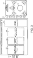
- FIG. 3 is a block diagram illustrating details of an exemplary embodiment of the constant-power pairwise panning upmixing system 300 and method shown in FIG. 1 .
- Embodiments of the system 300 and method operate in a computing environment (not shown), which is described in detail below.
- the system 300 and method are implemented on one or more computing devices including one or more processing devices.
- Input to the system 300 includes a two-channel input audio signal 310 having a Left Total channel (L T ) and a Right Total channel (R T ). These two channel are input to an inter-channel level difference (ICLD) and inter-channel phase difference (ICPD) computation module 320.
- the computation module 320 computes the inter-channel level difference for each channel using the two input channels.
- the computation module 320 calculates the inter-channel phase difference between the Left Total channel and the Right Total channel using the two input channels. This information is passed to a panning angle estimator 330.
- the estimator 330 estimates a panning angle for each output channel.
- the panning angle is the angle in the horizontal plane 250 from which the sound appears to originate during playback.
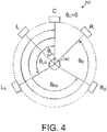
- FIG. 4 is an illustration of the concept of panning angle.
- a plan view of a 5.1 speaker configuration is shown situated in the horizontal plane 250.
- the panning angles of the speakers are illustrated.
- a panning angle may be any angle from 0 degrees to 359 degrees in the horizontal plane 250.
- a panning angle may be located between physical speakers such that the sound appears to originate from a virtual sound source.
- the Left speaker (L), which outputs information from the Left channel has certain panning angle denoted as a ll
- the Left Surround speaker (SL), which outputs information from the Left Surround channel has a certain panning angle denoted as l ess (which is greater than a ll ).
- the Right Surround speaker, which outputs information from the Right Surround channel has a certain panning angle denoted as y rs. (which is greater than l ess )
- the Right speaker, which outputs information from the Right channel has a certain panning angle denoted as y r. (which is greater than y rs. ).
- the panning angle estimations from the panning angle estimator 330 are passed to a coefficient calculator 340.
- the coefficient calculator 340 uses the estimated panning angle to calculate in-phase coefficients and out-of-phase coefficients (collectively called phase coefficients) for each output channel. Using these coefficients and the inter-channel phase difference, the coefficient calculator 340 determines the dematrixing coefficients for each output channel. These dematrixing coefficients and phase coefficients are passed to an output channel generator 350.
- the output channel generator 350 multiplies the Left Total channel and the Right Total channel by their corresponding dematrixing coefficients to generate the particular output channel.
- each output channel is a mixture of the Left Total channel and the Right Total channel. This mixture is determined by the dematrixing coefficients and especially the phase coefficients.
- the output channel generator 350 outputs an upmixed multi-channel output audio signal 360.
- the output audio signal is a 5.1 mix including all six channels of a 5.1 surround sound configuration.
- any numbers of channels may be generated as long as the number of channels is greater than two.
- each speaker in the target speaker layout 200 should lie approximately in the same horizontal plane as the listener's ears 260.
- the upmixed multi-channel output audio signal 360 is output for playback through speakers in the playback environment 190.
- FIG. 5 is a flow diagram illustrating the general operation of embodiments of the constant-power pairwise panning upmixing system 300 and method shown in FIGS. 1 and 3 .
- the operation begins by inputting a two-channel input audio signal having a first input channel and a second input channel (box 500).
- the method calculates a first dematrixing coefficient and a second dematrixing coefficient based on an inter-channel level difference (ICLD) and an inter-channel phase difference (ICPD) (box 510).
- ICLD inter-channel level difference
- ICPD inter-channel phase difference
- the method multiplies the first input channel by the first dematrixing coefficient to generate a first sub-signal (box 520).
- the method multiplies the second input channel by the second dematrixing coefficient to generate a second sub-signal (box 530).
- the method then mixes the first sub-signal and the second sub-signal together in a linear manner to generate an output channel (box 540). This process is repeated in a similar manner for each of the output channels by finding new dematrixing coefficients for each output channel (box 550). Although the dematrixing coefficients typically will be different for each output channel, this will not always be true.
- Each of the discrete output channels creates an upmixed multi-channel output audio signal for playback through playback devices (box 560), such as speakers or headphones.
- FIG. 6 is a flow diagram illustrating the details of an exemplary embodiment of the constant-power pairwise panning upmixing system 300 and method shown in FIGS. 1 , 3 , and 5 .
- the operation begins by inputting a two-channel input audio signal having a left input channel and a right input channel (box 600).
- the input signal is a stereo signal having a left and a right channel.
- the method then calculates an inter-channel level difference between the left and right channels using the left and right channels (box 610). This calculation is shown in detail below. Moreover, the method uses the inter-channel level difference to compute an estimated panning angle (box 620). In addition, an inter-channel phase difference is computed by the method using the left and right input channels (box 630). This inter-channel phase difference determines a relative phase difference between the left and right input channels that indicates whether the left and right signals of the two-channel input audio signal are in-phase or out-of-phase.
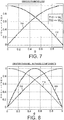
- FIG. 7 illustrates the panning weights as a function of the panning angle ( ⁇ ) for the Sin/Cos panning law.
- the first plot 700 represents the panning weights for the right channel (W R ).
- the second plot 710 represents the weights for the left channel (W L ).
- an estimate of the panning angle (or estimated panning angle, denoted as ⁇ ) can be calculated from the inter-channel level difference (denoted as ICLD).
- ICLD inter-channel level difference
- C sin ⁇ ⁇ ⁇
- Substituting the desired Center channel panning behavior for in-phase components and the assumed Sin/Cos downmix functions yields: sin ⁇ ⁇ ⁇ a ⁇ cos ⁇ ⁇ ⁇ 2 + b ⁇ sin ⁇ ⁇ ⁇ 2
- FIG. 11 illustrates two specific angles corresponding to downmix equations where the Left Surround and Right Surround channels are discretely encoded and decoded (these angles are approximately 0.25 and 0.75 (corresponding to 45° and 135°) on the out-of-phase plot 1100 in FIG. 11 ).
- the a and b coefficients for the Left Surround channel are generated via a piecewise function due to the piecewise behavior of the desired output.
- the a and b coefficients for the Right Surround channel generation are calculated similarly to those for the Left Surround channel generation as described above.
- the goal for the modified Left channel for in-phase components is to achieve panning behavior as illustrated by the in-phase plot 1200 in FIG. 12 .
- a panning angle ⁇ of 0.5 corresponds to a discrete Center channel.
- the a and b coefficients for the modified Left channel are generated via a piecewise function due to the piecewise behavior of the desired output.
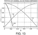
- the goal for the modified Left channel for out-of-phase components is to achieve panning behavior as illustrated by the out-of-phase plot 1300 in FIG. 13 .
- the a and b coefficients for the modified Left channel are generated via a piecewise function due to the piecewise behavior of the desired output.
- L ′ cos ⁇ ⁇ ⁇ Ls ⁇ 2 .
- L ′ 0.
- the a and b coefficients for the modified Right channel generation are calculated similarly to those for the modified Left channel generation as described above.
- the channel synthesis derivations presented above are based on achieving desired panning behavior for source content that is either in-phase or out-of-phase.
- ICPD Inter-Channel Phase Difference
- the ICPD value is bounded in the range [-1,1] where values of -1 indicate that the components are out-of-phase and values of 1 indicate that the components are in-phase.
- the ICPD property can then be used to determine the final a and b coefficients to use in the channel synthesis equations using linear interpolation. However, instead of interpolating the a and b coefficients directly, it can be noted that all of the a and b coefficients are generated using trigonometric functions of the panning angle estimate ⁇ .
- the linear interpolation is thus carried out on the angle arguments of the trigonometric functions.
- the channel outputs are computed as shown below.
- the first term in the argument of the sine function above represents the in-phase component of the first dematrixing coefficient, while the second term represents the out-of-phase component.
- ⁇ represents an in-phase coefficient and ⁇ represents an out-of-phase coefficient.
- the in-phase coefficient and the out-of phase coefficient are known as the phase coefficients.
- the method calculates the phase coefficients based on the estimated panning angle (box 640).
- the a and b coefficients for the Right Surround channel are generated similarly to
- the modified Left output channel is generated using the modified ICPD value as follows:
- L ′ aL ⁇ bR
- the modified Right output channel is generated using the modified ICPD value as follows:
- R ′ aR ⁇ bL
- the a and b coefficients for the Right channel are generated similarly to the Left channel, apart
- the subject matter discussed above is a system for generating Center, Left Surround, Right Surround, Left, and Right channels from a two-channel downmix.
- the system may be easily modified to generate other additional audio channels by defining additional panning behaviors.
- each output channel the method calculated the dematrixing coefficients based on the inter-channel phase difference and the phase coefficients (box 650). Moreover, the dematrixing coefficients contain both in-phase signal components and out-of-phase signal components. Further, each output channel is generated as different linear combinations of the right input channel and the left input channel weighted by their corresponding dematrixing coefficients (box 660).
- each output channel is output for reproduction in the playback environment 190 (box 670).
- the reproduction system may then play each audio channel over a target speaker layout. This playback will substantially recreate the original audio content before it was downmixed to two channels.
- a machine such as a general purpose processor, a processing device, a computing device having one or more processing devices, a digital signal processor (DSP), an application specific integrated circuit (ASIC), a field programmable gate array (FPGA) or other programmable logic device, discrete gate or transistor logic, discrete hardware components, or any combination thereof designed to perform the functions described herein.
- DSP digital signal processor
- ASIC application specific integrated circuit
- FPGA field programmable gate array
- a general purpose processor and processing device can be a microprocessor, but in the alternative, the processor can be a controller, microcontroller, or state machine, combinations of the same, or the like.
- a processor can also be implemented as a combination of computing devices, such as a combination of a DSP and a microprocessor, a plurality of microprocessors, one or more microprocessors in conjunction with a DSP core, or any other such configuration.
- Embodiments of the constant-power pairwise panning upmixing system 300 and method described herein are operational within numerous types of general purpose or special purpose computing system environments or configurations.
- a computing environment can include any type of computer system, including, but not limited to, a computer system based on one or more microprocessors, a mainframe computer, a digital signal processor, a portable computing device, a personal organizer, a device controller, a computational engine within an appliance, a mobile phone, a desktop computer, a mobile computer, a tablet computer, a smartphone, and appliances with an embedded computer, to name a few.
- Such computing devices can be typically be found in devices having at least some minimum computational capability, including, but not limited to, personal computers, server computers, hand-held computing devices, laptop or mobile computers, communications devices such as cell phones and PDA's, multiprocessor systems, microprocessor-based systems, set top boxes, programmable consumer electronics, network PCs, minicomputers, mainframe computers, audio or video media players, and so forth.
- the computing devices will include one or more processors.
- Each processor may be a specialized microprocessor, such as a digital signal processor (DSP), a very long instruction word (VLIW), or other microcontroller, or can be conventional central processing units (CPUs) having one or more processing cores, including specialized graphics processing unit (GPU)-based cores in a multi-core CPU.
- DSP digital signal processor
- VLIW very long instruction word
- CPUs central processing units
- GPU graphics processing unit
- the process actions of a method, process, or algorithm described in connection with the embodiments disclosed herein can be embodied directly in hardware, in a software module executed by a processor, or in any combination of the two.
- the software module can be contained in computer-readable media that can be accessed by a computing device.
- the computer-readable media includes both volatile and nonvolatile media that is either removable, non-removable, or some combination thereof.
- the computer-readable media is used to store information such as computer-readable or computer-executable instructions, data structures, program modules, or other data.
- computer readable media may comprise computer storage media and communication media.
- Computer storage media includes, but is not limited to, computer or machine readable media or storage devices such as Bluray discs (BD), digital versatile discs (DVDs), compact discs (CDs), floppy disks, tape drives, hard drives, optical drives, solid state memory devices, RAM memory, ROM memory, EPROM memory, EEPROM memory, flash memory or other memory technology, magnetic cassettes, magnetic tapes, magnetic disk storage, or other magnetic storage devices, or any other device which can be used to store the desired information and which can be accessed by one or more computing devices.
- BD Bluray discs
- DVDs digital versatile discs
- CDs compact discs
- floppy disks tape drives
- hard drives optical drives
- solid state memory devices random access memory
- RAM memory random access memory
- ROM memory read only memory
- EPROM memory erasable programmable read-only memory
- EEPROM memory electrically erasable programmable read-only memory
- flash memory or other memory technology
- magnetic cassettes magnetic tapes
- magnetic disk storage or other magnetic storage
- a software module can reside in the RAM memory, flash memory, ROM memory, EPROM memory, EEPROM memory, registers, hard disk, a removable disk, a CD-ROM, or any other form of non-transitory computer-readable storage medium, media, or physical computer storage known in the art.
- An exemplary storage medium can be coupled to the processor such that the processor can read information from, and write information to, the storage medium.
- the storage medium can be integral to the processor.
- the processor and the storage medium can reside in an application specific integrated circuit (ASIC).
- the ASIC can reside in a user terminal.
- the processor and the storage medium can reside as discrete components in a user terminal.
- non-transitory as used in this document means “enduring or long-lived”.
- non-transitory computer-readable media includes any and all computer-readable media, with the sole exception of a transitory, propagating signal. This includes, by way of example and not limitation, non-transitory computer-readable media such as register memory, processor cache and random-access memory (RAM).
- Retention of information such as computer-readable or computer-executable instructions, data structures, program modules, and so forth, can also be accomplished by using a variety of the communication media to encode one or more modulated data signals, electromagnetic waves (such as carrier waves), or other transport mechanisms or communications protocols, and includes any wired or wireless information delivery mechanism.
- these communication media refer to a signal that has one or more of its characteristics set or changed in such a manner as to encode information or instructions in the signal.
- communication media includes wired media such as a wired network or direct-wired connection carrying one or more modulated data signals, and wireless media such as acoustic, radio frequency (RF), infrared, laser, and other wireless media for transmitting, receiving, or both, one or more modulated data signals or electromagnetic waves. Combinations of the any of the above should also be included within the scope of communication media.
- RF radio frequency
- one or any combination of software, programs, computer program products that embody some or all of the various embodiments of the post-encoding bitrate reduction system 100 and method described herein, or portions thereof, may be stored, received, transmitted, or read from any desired combination of computer or machine readable media or storage devices and communication media in the form of computer executable instructions or other data structures.
- Embodiments of the constant-power pairwise panning upmixing system 300 and method described herein may be further described in the general context of computer-executable instructions, such as program modules, being executed by a computing device.
- program modules include routines, programs, objects, components, data structures, and so forth, which perform particular tasks or implement particular abstract data types.
- the embodiments described herein may also be practiced in distributed computing environments where tasks are performed by one or more remote processing devices, or within a cloud of one or more devices, that are linked through one or more communications networks.
- program modules may be located in both local and remote computer storage media including media storage devices.
- the aforementioned instructions may be implemented, in part or in whole, as hardware logic circuits, which may or may not include a processor.
Description
- This application claims the benefit of
U.S. Patent Application 14/447,516, filed July 30, 2014 U.S. Provisional Patent Application Serial Number 61/860,024 filed July 30, 2013 - Many audio reproduction systems are capable of recording, transmitting, and playing back synchronous multi-channel audio, sometimes referred to as "surround sound." Though entertainment audio began with simplistic monophonic systems, it soon developed two-channel (stereo) and higher channel-count formats (surround sound) in an effort to capture a convincing spatial image and sense of listener immersion. In particular, surround sound is a technique for enhancing reproduction of an audio signal by using more than two audio channels. Content is delivered over multiple discrete audio channels and reproduced using an array of loudspeakers (or speakers). The additional audio channels, or "surround channels," provide an immersive listening experience for a listener.
- Surround sound systems typically have speakers positioned around the listener to give the listener a sense of sound localization and envelopment. Many surround sound systems having only a few channels (such as a 5.1 format) have the speakers positioned in specific locations in a 360-degree arc about the listener. These speakers are arranged such that all of the speakers are in the same plane. Moreover, the listener's ears are also approximately in the same plane as each of the speakers. Higher-channel count surround sound systems (such 7.1, 11.1, and so forth) also include height or elevation speakers that are positioned above the plane of the listener's ears. Often these surround sound configurations include a discrete low-frequency effects (LFE) channel that provides additional low-frequency bass audio to supplement the bass audio in the other audio channels. Because this LFE channel requires only a portion of the bandwidth of the other audio channels, it is designated as the ".X" channel, where X is any positive integer including zero (as in 5.1 or 7.1 surround sound).
- Ideally surround sound audio is mixed into discrete channels and those channels are kept discrete through playback to the listener. In reality, however, storage and transmission limitations dictate that the file size of the surround sound audio be reduced to minimize storage space and transmission bandwidth. Moreover, two-channel audio content is typically compatible with a larger variety of broadcasting and reproduction systems as compared to audio content having more than two channels.
- Matrixing was developed to address these needs. Matrixing involves "downmixing" an original signal having more than two discrete audio channels into a two-channel audio signal. The additional channels are downmixed according to a pre-determined process to generate a two-channel downmix that includes information from all of the audio channels. The additional audio channels may later be extracted and synthesized from the two-channel downmix using an upmix process such that the original channel mix can be recovered to some level of approximation. Upmixing accepts the two-channel audio signal as input and generates a larger number of channels for playback. The playback is an acceptable approximation of the discrete audio channels of the original signal.
- Some upmixing techniques use constant-power panning. The concept of "panning" is derived from the film world and specifically the word "panorama." Panorama means to have a complete visual view of a given area in every direction. In the audio realm, audio can be panned in the stereo field so that the audio is perceived as being positioned in physical space such that all the sounds in a performance are heard by a listener in their proper location and dimension. For musical recordings, a common practice is to place the musical instruments where they would be physically located on a real stage. For example, stage left instruments are panned left and stage right instruments are panned right. This idea seeks to replicate a real-life performance for the listener during playback.
- Constant-power panning maintains constant signal power across audio channels as the input audio signal is distributed among them. Although constant-power panning is widespread, current downmixing and upmixing techniques struggle to preserve and recover the precise panning behavior and localization present in an original mix. In addition, some techniques are prone to artifacts, and all have limited ability to separate independent signals that overlap in time and frequency but originate from different spatial directions.
- For example, some popular upmixing techniques use voltage-controlled amplifiers to normalize both input channels to approximately the same level. These two signals then are combined in an ad-hoc manner to produce the output channels. Due to this ad-hoc approach, however, the final output has difficulty achieving desired panning behaviors and includes problems with crosstalk and at best approximates discrete surround-sound audio.
- Other types of upmixing techniques are precise only in a few panning locations but are imprecise away from those locations. By way of example, some upmixing techniques define a limited number of panning locations where upmixing results in precise and predictable behavior. Dominance vector analysis is used to interpolate between a limited number of pre-defined sets of dematrixing coefficients at the precise panning location points. Any panning location falling between the points use interpolation to find the dematrixing coefficient values. Due to this interpolation, panning locations falling between the precise points can be imprecise and adversely affect audio quality.
- Document
US 2008/205676 A1 discloses a frequency domain method for phase-amplitude matrixed surround decoding of 2-channel stereo recordings and soundtracks, based on spatial analysis of 2-D or 3-D directional cues in the recording and re-synthesis of these cues for reproduction on any headphone or loudspeaker playback system. - The invention provides a method performed by one or more processing devices for upmixing a two-channel input audio signal with the features of
claim 1. Embodiments of the invention are identified in the dependent claims. - Embodiments of the constant-power pairwise panning upmixing method preserve and recover the precise panning localization during the upmix process. This is achieved using a closed-form solution to generate precise and correct dematrixing coefficients. These dematrixing coefficients are used to determine how much of the original two channels are mixed into the new output channels. This closed-form solution precisely and exactly solves for the dematrixing coefficients at any panning locations. Any panning location can be precisely determined from the downmixed two-channel audio for any
point 360 degrees around the listener in the horizontal plane that includes the speakers and the listener's ears. - The precision of the closed-form solution leads to improved sound of the upmixed audio that is reproduced to a listener. By way of example and not limitation, assume that the audio content was originally mixed in two channels and contains a sequence where the audio is slowly panned from the left channel to the right channel using a Sin/Cos panning law. If the two channels are upmixed to a 5.1 target speaker layout using embodiments of the constant-power pairwise panning upmixing system and method, then that sequence will start at the left channel, then will slowly begin to pan to the center channel, as it gets to the center channel it will be discretely in the center, then it will begin to pan between the center and the right channel. The surround speakers will remain silent the entire time.
- On the other hand, because current upmixing techniques lack a closed-form solution framework, in the same situation the audio will start at the left channel and as it reaches the point between the left and center channels there will be leakage into the right channel and the surround channels. The audio will be discrete in the center channel because this is one of the pre-determined interpolation points. As the audio moves to the point between the center and right channels there will be leakage into the left channel and the surround channels. This is because when the audio is between the left and center channels and the right and center channels, current methods perform an interpolation of dematrixing coefficients. Because the dematrixing coefficients are not precisely correct there is leakage between channels.
- Embodiments of the constant-power pairwise panning upmixing system and method are used to upmix a stereo audio signal having two channels to a target speaker layout having more than two channels. The target speaker layout can have virtually any number of channels. However, embodiments of the constant-power pairwise panning upmixing system and method are restricted to target speaker layouts having speakers that are located approximately in the same plane as the listener's ears. This concept is discussed in more detail below.
- The constant-power pairwise panning upmixing system and method makes an assumption about the type of panning laws that were used during the creation of the audio content. In other words, the system and method assume that a certain panning law was used by either the downmixing process or by the mixing engineer. In some embodiments, the constant-power pairwise panning upmixing system and method assume a Sin/Cos pan law. In other embodiments, several different other types of panning laws may be used.
- The panning laws are assumed by embodiments of the constant-power pairwise panning upmixing system and method because it typically will not know the panning laws that were used in the creation or downmixing of the content. In addition, the system and method usually will receive as input one of two types of stereo input signals. Generally, therefore, the system, and method operates in one of two modes, and usually is not aware of which mode it is operating.
- The first mode is processing an already downmixed audio signal. For example, content that was originally recorded in 5.1 is downmixed to a matrix-encoded stereo signal and provided to the system and method. In this situation the matrix-encoded stereo signal is passed along to the upmixer for upmixing and rendering on a playback device. The second mode is used when the input is a stereo audio signal having stereo-mixed content that was original mixed in stereo and never downmixed. This includes, for example, content that was originally mixed into a legacy stereo signal and never downmixed. In this situation, the stereo signal is upmixed to a higher-channel count mix, such as a 7.1 mix.
- Regardless of the history of the input stereo signal, the signal is analyzed to recover an estimate of the underlying parameters that were used in the panning laws during content creation. These parameters include the panning angles that were used in the creation of the content. These estimated parameters are used during the upmix process to obtain dematrixing coefficients. The dematrixing coefficients are used to generate output channels with as accurate channel energies as when the original signal was created.
- The upmixed signal then is reproduced across the target speaker layout. Typically, the target speaker layout contains a channel count equal to or higher than the original audio signals. For example, the original stereo signal could be upmixed to a target speaker layout of 5.1, 7.1, or 9.1. As noted above, however, embodiments of the constant-power pairwise panning upmixing system and method are limited to speaker configurations that are roughly in the same plane as the listener's ears. In other words, each of the speakers in the target speaker layout is in the same plane, and that horizontal plane roughly includes both ears of the listener. This means that the target speaker layout does not include any out-of-horizontal plane speakers, such as height or elevated speakers.
- Embodiments of the constant-power pairwise panning upmixing system and method include upmixing a two-channel input audio signal having a first input channel and a second input channel into an upmixed multi-channel output audio signal having greater than two channels. The method calculates a first dematrixing coefficient and a second dematrixing coefficient based on an inter-channel level difference (ICLD) and an inter-channel phase difference (ICPD) between the first and second input channels. The method then multiplies the first input channel by the first dematrixing coefficient to generate a first sub-signal and multiplies the second input channel by the second dematrixing coefficient to generate a second sub-signal. These two sub-signals are mixed together in a linear manner to generate an output channel of the upmixed multi-channel output audio signal. The generated output channel is output for playback through a target speaker layout. The target speaker layout may include a plurality of speakers or may be headphones.
- Embodiments of the constant-power pairwise panning upmixing system and method also include a method for generating an upmixed multi-channel output audio signal having N output channels from a two-channel input audio signal having a left input channel and a right input channel. In addition, N is a positive integer greater than two. The method calculates the first dematrixing coefficient based on a first trigonometric function of a combination of an in-phase signal component and an out-of-phase signal component. In addition, the method calculates a second dematrixing coefficient based on a second trigonometric function of the combination of the in-phase signal component and the out-of-phase signal component.
- The method then generates each of the N output channels by mixing in a linear manner the first dematrixing coefficient times the left or right input channel and the second dematrixing coefficient times the right or left input channel. The method also causes each of the N output channels of the upmixed multi-channel output audio signal to be played back through speakers in a multi-channel playback environment.
- It should be noted that alternative embodiments are possible, and steps and elements discussed herein may be changed, added, or eliminated, depending on the particular embodiment. These alternative embodiments include alternative steps and alternative elements that may be used, and structural changes that may be made, without departing from the scope of the invention.
- Referring now to the drawings in which like reference numbers represent corresponding parts throughout:
-
FIG. 1 is a block diagram illustrating a general overview of embodiments of the constant-power pairwise panning upmixing system and method. -
FIG. 2 is an illustration of the concept of a target speaker layout having speakers in the same plane as the listener's ears. -
FIG. 3 is a block diagram illustrating details of an exemplary embodiment of the constant-power pairwise panning upmixing system and method shown inFIG. 1 . -
FIG. 4 is an illustration of the concept of panning angle. -
FIG. 5 is a flow diagram illustrating the general operation of embodiments of the constant-power pairwise panning upmixing system and method shown inFIGS. 1 and3 . -
FIG. 6 is a flow diagram illustrating the details of an exemplary embodiment of the constant-power pairwise panning upmixing system and method shown inFIGS. 1 ,3 , and5 . -
FIG. 7 illustrates the panning weights as a function of the panning angle (θ) for the Sin/Cos panning law. -
FIG. 8 illustrates panning behavior corresponding to an in-phase plot for a Center output channel. -
FIG. 9 illustrates panning behavior corresponding to an out-of-phase plot for the Center output channel. -
FIG. 10 illustrates panning behavior corresponding to an in-phase plot for a Left Surround output channel. -
FIG. 11 illustrates two specific angles corresponding to downmix equations where the Left Surround and Right Surround channels are discretely encoded and decoded. -
FIG. 12 illustrates panning behavior corresponding to an in-phase plot for a modified Left output channel. -
FIG. 13 illustrates panning behavior corresponding to an out-of-phase plot for the modified Left output channel. - In the following description of embodiments of a constant-power pairwise panning upmixing system and method reference is made to the accompanying drawings. These drawings shown by way of illustration specific examples of how embodiments of the constant-power pairwise panning upmixing system and method may be practiced. It is understood that other embodiments may be utilized and structural changes may be made without departing from the scope of the claimed subject matter.
- Embodiments of the constant-power pairwise panning upmixing system and method upmix a two-channel input audio signal to a multi-channel output audio signal having more than two channels using a closed-form solution to precisely determine dematrixing coefficients. These dematrixing coefficients are used to weight each of the two input channels and determine how much of each input channel is contained in each output channel. Embodiments of the constant-power pairwise panning upmixing system and method are used to create a surround sound experience with multiple output channels for a listener when the input is a stereo signal.
-
FIG. 1 is a block diagram illustrating a general overview of embodiments of the constant-power pairwise panning upmixing system and method. Referring toFIG. 1 , audio content (such as musical tracks) is created in acontent creation environment 100. Thisenvironment 100 may include a plurality of microphones 105 (or other sound-capturing devices) to record audio sources. Alternatively, the audio sources may already be a digital signal such that it is not necessary to use a microphone to record the source. Whatever the method of creating the sound, each of the audio sources is mixed into a final mix as the output of thecontent creation environment 100. - In
FIG. 1 , the final mix is a final 5.1mix 110 such that each of the audio sources is mixed into six channels including a Left channel (L), a Right channel (R), a Center channel (C), a Left Surround channel (LS), a Right Surround channel (RS), and a Low-Frequency Effects (LFE) channel. Although the final mix shown inFIG. 1 is a 5.1 mix, it should be noted that other final mixes are possible, including a mix having a greater number of channels and a mix having a lesser number of channels (such as a stereo or mono mix). The final 5.1mix 110 then is encoded and downmixed (if necessary) using a matrix encoder anddownmixer 120. The matrix encoder anddownmixer 120 are typically located on a computing device having one or more processing devices. The matrix encoder anddownmixer 120 encodes and downmixes the final 5.1 mix into astereo mix 130 having a Left Total channel (LT) and a Right Total channel (RT). - The
stereo mix 130 is delivered for consumption by a listener in adelivery environment 140. Several delivery options are available, including streaming delivery over anetwork 150. Alternatively, thestereo mix 130 may be recorded on amedia 160 such as optical disk or film for consumption by the listener. In addition, there is many other delivery options not enumerated here that may be used to deliver thestereo mix 130. - Whatever the delivery method, the
stereo mix 130 is input to a matrix decoder andupmixer 170. The matrix decoder andupmixer 170 includes embodiments of the constant-power pairwise panning upmixing system and method. The matrix encoder anddownmixer 120 and embodiments of the constant-power pairwise panning upmixing system and method 180 are typically located on a computing device having one or more processing devices. - The matrix decoder and
upmixer 170 decodes each channel of thestereo mix 130 and expands them into discrete output channels. InFIG. 1 is shown a reconstructed 5.1mix 185 that is thestereo mix 130 expanded into a 5.1 output. This reconstructed 5.1mix 185 is reproduced in aplayback environment 190 that includes a target speaker layout including speakers that correspond to the reconstructed channels. These speakers include a Left speaker, a Right speaker, a Center speaker, a Left Surround speaker, a Right Surround speaker, and a LFE speaker. In other embodiments, the target speaker layout may be headphones such that the speakers are merely virtual speakers from which sound appears to originate in theplayback environment 190. For example, thelistener 195 may be listening to the reconstructed 5.1 mix through headphones. In this situation, the speakers are not actual physical speakers but sounds appear to originate from different spatial locations in the playback environment corresponding, for example, a 5.1 surround sound speaker configuration. - Whether the target speaker layout is actual speakers or headphones, the playback of the reconstructed 5.1
mix 185 provides thelistener 195 with an immersive surround sound experience from a stereo input audio signal. It should be noted that although the target speaker layout is a 5.1 configuration, in other embodiments any number of speakers may be used as long as the number is greater than two. - Embodiments of the constant-power pairwise panning upmixing system 180 and method are designed such that the
playback environment 190 includes speakers that are located in the same horizontal plane and that plane includes the listener's ears.FIG. 2 is an illustration of the concept of atarget speaker layout 200 having speakers in the same plane as the listener's ears. As shown inFIG. 2 , thelistener 195 is listening to content that is rendered on thetarget speaker layout 200. Thetarget speaker layout 200 is a 5.1 layout having aleft speaker 210, acenter speaker 215, aright speaker 220, aleft surround speaker 225, and aright surround speaker 230. The 5.1 layout shown also includes a low-frequency effects (LFE or "subwoofer")speaker 235. In some embodiments thetarget speaker layout 200 is a 7.1 layout. The two additional speakers are shown as dashed lines to indicate that they are optional. These two additional speakers include a surround back leftspeaker 240 and a surround backright speaker 245. - Each of the speakers is located in a
horizontal plane 250. In addition, each of the listener'sears 260 also is located in thehorizontal plane 250. Although a 5.1 and 7.1 layout are shown inFIG. 2 , embodiments of the constant-power pairwise panning upmixing system 180 and method can be generalized such that content could be upmixed from any stereo layout into any layout in thehorizontal plane 250 of the user'sear 260 encircling the user. - It should be noted that in
FIG. 2 the speakers in the target speaker layout and the listener's head and ears are not to scale with each other. In particular, the listener's head and ears are shown larger than scale to illustrate the concept that each of the speakers and the listener's ears are in the samehorizontal plane 250. - The system details of components of embodiments of the constant-power pairwise panning upmixing system will now be discussed. It should be noted that only a few of the several ways in which the system may be implemented are detailed below. Many variations are possible from that which is shown in
FIG. 3. FIG. 3 is a block diagram illustrating details of an exemplary embodiment of the constant-power pairwise panningupmixing system 300 and method shown inFIG. 1 . Embodiments of thesystem 300 and method operate in a computing environment (not shown), which is described in detail below. In particular, thesystem 300 and method are implemented on one or more computing devices including one or more processing devices. - Input to the
system 300 includes a two-channel inputaudio signal 310 having a Left Total channel (LT) and a Right Total channel (RT). These two channel are input to an inter-channel level difference (ICLD) and inter-channel phase difference (ICPD)computation module 320. Thecomputation module 320 computes the inter-channel level difference for each channel using the two input channels. Moreover, thecomputation module 320 calculates the inter-channel phase difference between the Left Total channel and the Right Total channel using the two input channels. This information is passed to apanning angle estimator 330. - Based on the inter-channel level difference, the
estimator 330 estimates a panning angle for each output channel. The panning angle is the angle in thehorizontal plane 250 from which the sound appears to originate during playback.FIG. 4 is an illustration of the concept of panning angle. InFIG. 4 , a plan view of a 5.1 speaker configuration is shown situated in thehorizontal plane 250. InFIG. 4 the panning angles of the speakers are illustrated. However, it is possible that a panning angle may be any angle from 0 degrees to 359 degrees in thehorizontal plane 250. In other words, a panning angle may be located between physical speakers such that the sound appears to originate from a virtual sound source. - In
FIG. 4 , the Center speaker (C), which outputs information from the Center channel, is designated as the origin and has a panning angle of 0 degrees (act = 0). Moving counterclockwise from the Center speaker, the Left speaker (L), which outputs information from the Left channel, has certain panning angle denoted as all, and the Left Surround speaker (SL), which outputs information from the Left Surround channel, has a certain panning angle denoted as less (which is greater than all). In addition, the Right Surround speaker, which outputs information from the Right Surround channel, has a certain panning angle denoted as yrs. (which is greater than less), and the Right speaker, which outputs information from the Right channel, has a certain panning angle denoted as yr. (which is greater than yrs.). - The panning angle estimations from the panning
angle estimator 330 are passed to acoefficient calculator 340. Thecoefficient calculator 340 uses the estimated panning angle to calculate in-phase coefficients and out-of-phase coefficients (collectively called phase coefficients) for each output channel. Using these coefficients and the inter-channel phase difference, thecoefficient calculator 340 determines the dematrixing coefficients for each output channel. These dematrixing coefficients and phase coefficients are passed to anoutput channel generator 350. - For each output channel, the
output channel generator 350 multiplies the Left Total channel and the Right Total channel by their corresponding dematrixing coefficients to generate the particular output channel. Thus, at any given time during playback of audio content each output channel is a mixture of the Left Total channel and the Right Total channel. This mixture is determined by the dematrixing coefficients and especially the phase coefficients. - Once all of the discrete output channels have been generated, the
output channel generator 350 outputs an upmixed multi-channeloutput audio signal 360. In the exemplary example shown inFIG. 3 , the output audio signal is a 5.1 mix including all six channels of a 5.1 surround sound configuration. In other embodiments of thesystem 300 and method, any numbers of channels may be generated as long as the number of channels is greater than two. In addition, as noted above, each speaker in thetarget speaker layout 200 should lie approximately in the same horizontal plane as the listener'sears 260. The upmixed multi-channeloutput audio signal 360 is output for playback through speakers in theplayback environment 190. -
FIG. 5 is a flow diagram illustrating the general operation of embodiments of the constant-power pairwise panningupmixing system 300 and method shown inFIGS. 1 and3 . The operation begins by inputting a two-channel input audio signal having a first input channel and a second input channel (box 500). Next, the method calculates a first dematrixing coefficient and a second dematrixing coefficient based on an inter-channel level difference (ICLD) and an inter-channel phase difference (ICPD) (box 510). The method then multiplies the first input channel by the first dematrixing coefficient to generate a first sub-signal (box 520). In addition, the method multiplies the second input channel by the second dematrixing coefficient to generate a second sub-signal (box 530). - The method then mixes the first sub-signal and the second sub-signal together in a linear manner to generate an output channel (box 540). This process is repeated in a similar manner for each of the output channels by finding new dematrixing coefficients for each output channel (box 550). Although the dematrixing coefficients typically will be different for each output channel, this will not always be true. Each of the discrete output channels creates an upmixed multi-channel output audio signal for playback through playback devices (box 560), such as speakers or headphones.
- The operational details of embodiments of the constant-power pairwise panning
upmixing system 300 and method now will be discussed.FIG. 6 is a flow diagram illustrating the details of an exemplary embodiment of the constant-power pairwise panningupmixing system 300 and method shown inFIGS. 1 ,3 , and5 . As shown inFIG. 6 , the operation begins by inputting a two-channel input audio signal having a left input channel and a right input channel (box 600). Thus, the input signal is a stereo signal having a left and a right channel. - The method then calculates an inter-channel level difference between the left and right channels using the left and right channels (box 610). This calculation is shown in detail below. Moreover, the method uses the inter-channel level difference to compute an estimated panning angle (box 620). In addition, an inter-channel phase difference is computed by the method using the left and right input channels (box 630). This inter-channel phase difference determines a relative phase difference between the left and right input channels that indicates whether the left and right signals of the two-channel input audio signal are in-phase or out-of-phase.
- Some embodiments of the constant-power pairwise panning
upmixing system 300 and method utilize a panning angle (θ) to determine the downmix process and subsequent upmix process from the two-channel downmix. Moreover, some embodiments assume a Sin/Cos panning law. In these situations, the two-channel downmix is calculated as a function of the panning angle as:

-
FIG. 7 illustrates the panning weights as a function of the panning angle (θ) for the Sin/Cos panning law. Thefirst plot 700 represents the panning weights for the right channel (WR). Thesecond plot 710 represents the weights for the left channel (WL). By way of example and referring toFIG. 7 , a center channel may use a panning angle of 0.5 leading to the downmix functions:

- To synthesize the additional audio channels from a two-channel downmix, an estimate of the panning angle (or estimated panning angle, denoted as θ̂) can be calculated from the inter-channel level difference (denoted as ICLD). Let the ICLD be defined as:

- Assuming that a signal component is generated via intensity panning using the Sin/Cos panning law, the ICLD can be expressed as a function of the panning angle estimate:


- The following angle sum and difference identities will be used throughout the remaining derivations:


- A Center channel is generated from a two-channel downmix using the following equation:

- For the in-phase components of the Center channel a desired panning behavior is illustrated in
FIG. 8. FIG. 8 illustrates panning behavior corresponding to an in-phase plot 800 given by the equation:


- For the out-of-phase components of the Center channel a desired panning behavior is illustrated in
FIG. 9. FIG. 9 illustrates panning behavior corresponding to an out-of-phase plot 900 given by the equation:


- The surround channels are generated from a two-channel downmix using the following equations:


- The ideal panning behavior for in-phase components of the Left Surround channel is illustrated in
FIG. 10. FIG. 10 illustrates panning behavior corresponding to an in-phase plot 1000 given by the equation:
- Substituting the desired Left Surround channel panning behavior for in-phase components and the assumed Sin/Cos downmix functions leads to:

- Using the angle sum identities, the a and b coefficients are derived as:


- The goal for the Left Surround channel for out-of-phase components is to achieve panning behavior as illustrated by the out-of-
phase plot 1100 inFIG. 11. FIG. 11 illustrates two specific angles corresponding to downmix equations where the Left Surround and Right Surround channels are discretely encoded and decoded (these angles are approximately 0.25 and 0.75 (corresponding to 45° and 135°) on the out-of-phase plot 1100 inFIG. 11 ). These angles are referred to as:

- The a and b coefficients for the Left Surround channel are generated via a piecewise function due to the piecewise behavior of the desired output. For θ̂ ≤ θLs, the desired panning behavior for the Left Surround channel corresponds to:

- Substituting the desired Left Surround channel panning behavior for out-of-phase components and the assumed Sin/Cos downmix functions leads to:

- Using the angle sum identities, the a and b coefficients can be derived as:


- For θLs < θ̂ ≤ θRs , the desired panning behavior for the Left Surround channel corresponds to:

- Substituting the desired Left Surround channel panning behavior for out-of-phase components and the assumed Sin/Cos downmix functions leads to:

- Using the angle sum identities, the a and b coefficients can be derived as:


- For θ̂ > θRs , the desired panning behavior for the Left Surround channel corresponds to:

- Substituting the desired Left Surround channel panning behavior for out-of-phase components and the assumed Sin/Cos downmix functions leads to:

- Using the angle sum identities, the a and b coefficients can be derived as:


- The a and b coefficients for the Right Surround channel generation are calculated similarly to those for the Left Surround channel generation as described above.
- The Left and Right channels are modified using the following equations to remove (either fully or partially) those components generated in the Center and Surround channels:


- The goal for the modified Left channel for in-phase components is to achieve panning behavior as illustrated by the in-
phase plot 1200 inFIG. 12 . InFIG. 12 , a panning angle θ of 0.5 corresponds to a discrete Center channel. The a and b coefficients for the modified Left channel are generated via a piecewise function due to the piecewise behavior of the desired output. - For θ̂ ≤ 0.5, the desired panning behavior for the modified Left channel corresponds to:

- Substituting the desired modified Left channel panning behavior for in-phase components and the assumed Sin/Cos downmix functions leads to:

- Using the angle sum identities, the a and b coefficients can be derived as:


- For θ̂ > 0.5, the desired panning behavior for the modified Left channel corresponds to:


- Using the angle sum identities, the a and b coefficients can be derived as:


- The goal for the modified Left channel for out-of-phase components is to achieve panning behavior as illustrated by the out-of-
phase plot 1300 inFIG. 13 . InFIG. 13 , a panning angle θ = θLs corresponds to the encoding angle for the Left Surround channel. The a and b coefficients for the modified Left channel are generated via a piecewise function due to the piecewise behavior of the desired output. - For θ̂ ≤ θLs, the desired panning behavior for the modified Left channel corresponds to:


- Using the angle sum identities, the a and b coefficients can be derived as:


- For θ̂ > θLs, the desired panning behavior for the modified Left channel corresponds to:


- Using the angle sum identities, the a and b coefficients can be derived as:


- The channel synthesis derivations presented above are based on achieving desired panning behavior for source content that is either in-phase or out-of-phase. The relative phase difference of the source content can be determined through the Inter-Channel Phase Difference (ICPD) property defined as:

- The ICPD value is bounded in the range [-1,1] where values of -1 indicate that the components are out-of-phase and values of 1 indicate that the components are in-phase. The ICPD property can then be used to determine the final a and b coefficients to use in the channel synthesis equations using linear interpolation. However, instead of interpolating the a and b coefficients directly, it can be noted that all of the a and b coefficients are generated using trigonometric functions of the panning angle estimate θ̂.
- The linear interpolation is thus carried out on the angle arguments of the trigonometric functions. Performing the linear interpolation in this manner has two main advantages. First, it preserves the property that a 2 + b 2 = 1 for any panning angle and ICPD value. Second, it reduces the number of trigonometric function calls required thereby reducing processing requirements.
- The angle interpolation uses a modified ICPD value normalized to the range [0,1] calculated as:

- The Center output channel is generated using the modified ICPD value, which is defined as:


- Referring again to
FIG. 6 , for each output channel the method calculates the phase coefficients based on the estimated panning angle (box 640). For the Center output channel, the in-phase coefficient and the out-of-phase coefficient are given as:

- The Left Surround output channel is generated using the modified ICPD value, which is defined as:


- The Right Surround output channel is generated using the modified ICPD value, which is defined as:


- The modified Left output channel is generated using the modified ICPD value as follows:


- The modified Right output channel is generated using the modified ICPD value as follows:


- The subject matter discussed above is a system for generating Center, Left Surround, Right Surround, Left, and Right channels from a two-channel downmix. However, the system may be easily modified to generate other additional audio channels by defining additional panning behaviors.
- Referring again to
FIG. 6 , it can be seen from the above discussion that for each output channel the method calculated the dematrixing coefficients based on the inter-channel phase difference and the phase coefficients (box 650). Moreover, the dematrixing coefficients contain both in-phase signal components and out-of-phase signal components. Further, each output channel is generated as different linear combinations of the right input channel and the left input channel weighted by their corresponding dematrixing coefficients (box 660). - After generating the output channels to obtain the upmixed multi-channel output audio signal, each output channel is output for reproduction in the playback environment 190 (box 670). The reproduction system may then play each audio channel over a target speaker layout. This playback will substantially recreate the original audio content before it was downmixed to two channels.
- Many other variations than those described herein will be apparent from this document. For example, depending on the embodiment, certain acts, events, or functions of any of the methods and algorithms described herein can be performed in a different sequence, can be added, merged, or left out altogether (such that not all described acts or events are necessary for the practice of the methods and algorithms). Moreover, in certain embodiments, acts or events can be performed concurrently, such as through multi-threaded processing, interrupt processing, or multiple processors or processor cores or on other parallel architectures, rather than sequentially. In addition, different tasks or processes can be performed by different machines and computing systems that can function together.
- The various illustrative logical blocks, modules, methods, and algorithm processes and sequences described in connection with the embodiments disclosed herein can be implemented as electronic hardware, computer software, or combinations of both. To clearly illustrate this interchangeability of hardware and software, various illustrative components, blocks, modules, and process actions have been described above generally in terms of their functionality. Whether such functionality is implemented as hardware or software depends upon the particular application and design constraints imposed on the overall system. The described functionality can be implemented in varying ways for each particular application, but such implementation decisions should not be interpreted as causing a departure from the scope of this document.
- The various illustrative logical blocks and modules described in connection with the embodiments disclosed herein can be implemented or performed by a machine, such as a general purpose processor, a processing device, a computing device having one or more processing devices, a digital signal processor (DSP), an application specific integrated circuit (ASIC), a field programmable gate array (FPGA) or other programmable logic device, discrete gate or transistor logic, discrete hardware components, or any combination thereof designed to perform the functions described herein. A general purpose processor and processing device can be a microprocessor, but in the alternative, the processor can be a controller, microcontroller, or state machine, combinations of the same, or the like. A processor can also be implemented as a combination of computing devices, such as a combination of a DSP and a microprocessor, a plurality of microprocessors, one or more microprocessors in conjunction with a DSP core, or any other such configuration.
- Embodiments of the constant-power pairwise panning
upmixing system 300 and method described herein are operational within numerous types of general purpose or special purpose computing system environments or configurations. In general, a computing environment can include any type of computer system, including, but not limited to, a computer system based on one or more microprocessors, a mainframe computer, a digital signal processor, a portable computing device, a personal organizer, a device controller, a computational engine within an appliance, a mobile phone, a desktop computer, a mobile computer, a tablet computer, a smartphone, and appliances with an embedded computer, to name a few. - Such computing devices can be typically be found in devices having at least some minimum computational capability, including, but not limited to, personal computers, server computers, hand-held computing devices, laptop or mobile computers, communications devices such as cell phones and PDA's, multiprocessor systems, microprocessor-based systems, set top boxes, programmable consumer electronics, network PCs, minicomputers, mainframe computers, audio or video media players, and so forth. In some embodiments the computing devices will include one or more processors. Each processor may be a specialized microprocessor, such as a digital signal processor (DSP), a very long instruction word (VLIW), or other microcontroller, or can be conventional central processing units (CPUs) having one or more processing cores, including specialized graphics processing unit (GPU)-based cores in a multi-core CPU.
- The process actions of a method, process, or algorithm described in connection with the embodiments disclosed herein can be embodied directly in hardware, in a software module executed by a processor, or in any combination of the two. The software module can be contained in computer-readable media that can be accessed by a computing device. The computer-readable media includes both volatile and nonvolatile media that is either removable, non-removable, or some combination thereof. The computer-readable media is used to store information such as computer-readable or computer-executable instructions, data structures, program modules, or other data. By way of example, and not limitation, computer readable media may comprise computer storage media and communication media.
- Computer storage media includes, but is not limited to, computer or machine readable media or storage devices such as Bluray discs (BD), digital versatile discs (DVDs), compact discs (CDs), floppy disks, tape drives, hard drives, optical drives, solid state memory devices, RAM memory, ROM memory, EPROM memory, EEPROM memory, flash memory or other memory technology, magnetic cassettes, magnetic tapes, magnetic disk storage, or other magnetic storage devices, or any other device which can be used to store the desired information and which can be accessed by one or more computing devices.
- A software module can reside in the RAM memory, flash memory, ROM memory, EPROM memory, EEPROM memory, registers, hard disk, a removable disk, a CD-ROM, or any other form of non-transitory computer-readable storage medium, media, or physical computer storage known in the art. An exemplary storage medium can be coupled to the processor such that the processor can read information from, and write information to, the storage medium. In the alternative, the storage medium can be integral to the processor. The processor and the storage medium can reside in an application specific integrated circuit (ASIC). The ASIC can reside in a user terminal. Alternatively, the processor and the storage medium can reside as discrete components in a user terminal.
- The phrase "non-transitory" as used in this document means "enduring or long-lived". The phrase "non-transitory computer-readable media" includes any and all computer-readable media, with the sole exception of a transitory, propagating signal. This includes, by way of example and not limitation, non-transitory computer-readable media such as register memory, processor cache and random-access memory (RAM).
- Retention of information such as computer-readable or computer-executable instructions, data structures, program modules, and so forth, can also be accomplished by using a variety of the communication media to encode one or more modulated data signals, electromagnetic waves (such as carrier waves), or other transport mechanisms or communications protocols, and includes any wired or wireless information delivery mechanism. In general, these communication media refer to a signal that has one or more of its characteristics set or changed in such a manner as to encode information or instructions in the signal. For example, communication media includes wired media such as a wired network or direct-wired connection carrying one or more modulated data signals, and wireless media such as acoustic, radio frequency (RF), infrared, laser, and other wireless media for transmitting, receiving, or both, one or more modulated data signals or electromagnetic waves. Combinations of the any of the above should also be included within the scope of communication media.
- Further, one or any combination of software, programs, computer program products that embody some or all of the various embodiments of the post-encoding
bitrate reduction system 100 and method described herein, or portions thereof, may be stored, received, transmitted, or read from any desired combination of computer or machine readable media or storage devices and communication media in the form of computer executable instructions or other data structures. - Embodiments of the constant-power pairwise panning
upmixing system 300 and method described herein may be further described in the general context of computer-executable instructions, such as program modules, being executed by a computing device. Generally, program modules include routines, programs, objects, components, data structures, and so forth, which perform particular tasks or implement particular abstract data types. The embodiments described herein may also be practiced in distributed computing environments where tasks are performed by one or more remote processing devices, or within a cloud of one or more devices, that are linked through one or more communications networks. In a distributed computing environment, program modules may be located in both local and remote computer storage media including media storage devices. Still further, the aforementioned instructions may be implemented, in part or in whole, as hardware logic circuits, which may or may not include a processor. - Conditional language used herein, such as, among others, "can," "might," "may," "e.g.," and the like, unless specifically stated otherwise, or otherwise understood within the context as used, is generally intended to convey that certain embodiments include, while other embodiments do not include, certain features, elements and/or states. Thus, such conditional language is not generally intended to imply that features, elements and/or states are in any way required for one or more embodiments or that one or more embodiments necessarily include logic for deciding, with or without author input or prompting, whether these features, elements and/or states are included or are to be performed in any particular embodiment. The terms "comprising," "including," "having," and the like are synonymous and are used inclusively, in an open-ended fashion, and do not exclude additional elements, features, acts, operations, and so forth. Also, the term "or" is used in its inclusive sense (and not in its exclusive sense) so that when used, for example, to connect a list of elements, the term "or" means one, some, or all of the elements in the list.
- While the above detailed description has shown, described, and pointed out novel features as applied to various embodiments, it will be understood that various omissions, substitutions, and changes in the form and details of the devices or algorithms illustrated can be made without departing from the spirit of the disclosure. As will be recognized, certain embodiments of the inventions described herein can be embodied within a form that does not provide all of the features and benefits set forth herein, as some features can be used or practiced separately from others.
- Moreover, although the subject matter has been described in language specific to structural features and methodological acts, it is to be understood that the subject matter defined in the appended claims is not necessarily limited to the specific features or acts described above. Rather, the specific features and acts described above are disclosed as example forms of implementing the claims.
Claims (7)
- A method performed by one or more processing devices for upmixing a two-channel input audio signal having a first input channel and a second input channel into an upmixed multi-channel output audio signal having greater than two channels, comprising:calculating an estimated panning angle from an inter-channel level difference between the first and second input channels;calculating an in-phase coefficient and an out-of-phase coefficient using the estimated panning angle;calculating a first dematrixing coefficient and a second dematrixing coefficient based on an inter-channel phase difference between the first and second input channels, the in-phase coefficient and the out-of-phase coefficient;multiplying the first input channel by the first dematrixing coefficient to generate a first sub-signal and the second input channel by the second dematrixing coefficient to generate a second sub-signal;mixing the first sub-signal and the second sub-signal in a linear manner to generate an output channel of the upmixed multi-channel output audio signal; andoutputting the generated output channel for playback through speakers;characterised in that calculating the dematrixing coefficients comprises:calculating an in-phase signal component, based on the inter-channel phase difference multiplied by the in-phase coefficient, and calculating an out-of-phase signal component, based on the inter-channel phase difference multiplied by the out-of-phase coefficient; andcalculating the first dematrixing coefficient based on a first trigonometric function of a combination of the in-phase signal component and the out-of-phase signal component, and calculating the second dematrixing coefficient based on a second trigonometric function of the combination of the in-phase signal component and the out-of-phase signal component.
- The method of claim 1, further comprising calculating the inter-channel level difference for the two-channel input audio signal as a ratio of a left channel and a sum of the left channel and a right channel.
- The method of claim 2, wherein calculating the inter-channel level difference further comprises using the equation:

- The method of claim 1, wherein calculating the estimated panning angle (θ̂) further comprises using the equation:

- The method of claim 4, wherein the estimated panning angle is an estimate of an original panning angle associated with the two-channel input audio signal.
- The method of claim 1, wherein calculating the first and second dematrixing coefficients further comprises:
determining the inter-channel phase difference (ICLD) between the first and the second input channels, based on the equation:
- The method of claim 1, wherein calculating the first and second dematrixing coefficients further comprises:calculating the first dematrixing coefficient using the equation:
 calculating the second dematrixing coefficient using the equation:


Priority Applications (3)
| Application Number | Priority Date | Filing Date | Title |
|---|---|---|---|
| PL18191388T PL3429233T3 (en) | 2013-07-30 | 2014-07-30 | Matrix decoder with constant-power pairwise panning |
| EP18191388.0A EP3429233B1 (en) | 2013-07-30 | 2014-07-30 | Matrix decoder with constant-power pairwise panning |
| PL14832121T PL3028474T3 (en) | 2013-07-30 | 2014-07-30 | Matrix decoder with constant-power pairwise panning |
Applications Claiming Priority (2)
| Application Number | Priority Date | Filing Date | Title |
|---|---|---|---|
| US201361860024P | 2013-07-30 | 2013-07-30 | |
| PCT/US2014/048975 WO2015017584A1 (en) | 2013-07-30 | 2014-07-30 | Matrix decoder with constant-power pairwise panning |
Related Child Applications (2)
| Application Number | Title | Priority Date | Filing Date |
|---|---|---|---|
| EP18191388.0A Division EP3429233B1 (en) | 2013-07-30 | 2014-07-30 | Matrix decoder with constant-power pairwise panning |
| EP18191388.0A Division-Into EP3429233B1 (en) | 2013-07-30 | 2014-07-30 | Matrix decoder with constant-power pairwise panning |
Publications (3)
| Publication Number | Publication Date |
|---|---|
| EP3028474A1 EP3028474A1 (en) | 2016-06-08 |
| EP3028474A4 EP3028474A4 (en) | 2017-07-05 |
| EP3028474B1 true EP3028474B1 (en) | 2018-12-19 |
Family
ID=52427693
Family Applications (2)
| Application Number | Title | Priority Date | Filing Date |
|---|---|---|---|
| EP18191388.0A Active EP3429233B1 (en) | 2013-07-30 | 2014-07-30 | Matrix decoder with constant-power pairwise panning |
| EP14832121.9A Active EP3028474B1 (en) | 2013-07-30 | 2014-07-30 | Matrix decoder with constant-power pairwise panning |
Family Applications Before (1)
| Application Number | Title | Priority Date | Filing Date |
|---|---|---|---|
| EP18191388.0A Active EP3429233B1 (en) | 2013-07-30 | 2014-07-30 | Matrix decoder with constant-power pairwise panning |
Country Status (8)
| Country | Link |
|---|---|
| US (2) | US9338573B2 (en) |
| EP (2) | EP3429233B1 (en) |
| JP (1) | JP6543627B2 (en) |
| KR (1) | KR102114440B1 (en) |
| CN (1) | CN105594227B (en) |
| HK (1) | HK1218596A1 (en) |
| PL (2) | PL3028474T3 (en) |
| WO (1) | WO2015017584A1 (en) |
Families Citing this family (6)
| Publication number | Priority date | Publication date | Assignee | Title |
|---|---|---|---|---|
| US20170289724A1 (en) * | 2014-09-12 | 2017-10-05 | Dolby Laboratories Licensing Corporation | Rendering audio objects in a reproduction environment that includes surround and/or height speakers |
| CN107452387B (en) * | 2016-05-31 | 2019-11-12 | 华为技术有限公司 | A kind of extracting method and device of interchannel phase differences parameter |
| US9820073B1 (en) | 2017-05-10 | 2017-11-14 | Tls Corp. | Extracting a common signal from multiple audio signals |
| JP7024794B2 (en) * | 2017-09-06 | 2022-02-24 | ヤマハ株式会社 | Audio systems, audio equipment, and how to control audio equipment |
| TWI719429B (en) * | 2019-03-19 | 2021-02-21 | 瑞昱半導體股份有限公司 | Audio processing method and audio processing system |
| KR20210072388A (en) | 2019-12-09 | 2021-06-17 | 삼성전자주식회사 | Audio outputting apparatus and method of controlling the audio outputting appratus |
Family Cites Families (29)
| Publication number | Priority date | Publication date | Assignee | Title |
|---|---|---|---|---|
| US5291557A (en) | 1992-10-13 | 1994-03-01 | Dolby Laboratories Licensing Corporation | Adaptive rematrixing of matrixed audio signals |
| US5319713A (en) | 1992-11-12 | 1994-06-07 | Rocktron Corporation | Multi dimensional sound circuit |
| US5638452A (en) | 1995-04-21 | 1997-06-10 | Rocktron Corporation | Expandable multi-dimensional sound circuit |
| US5771295A (en) | 1995-12-26 | 1998-06-23 | Rocktron Corporation | 5-2-5 matrix system |
| US5870480A (en) | 1996-07-19 | 1999-02-09 | Lexicon | Multichannel active matrix encoder and decoder with maximum lateral separation |
| US6665407B1 (en) | 1998-09-28 | 2003-12-16 | Creative Technology Ltd. | Three channel panning system |
| US6507658B1 (en) | 1999-01-27 | 2003-01-14 | Kind Of Loud Technologies, Llc | Surround sound panner |
| US7003467B1 (en) | 2000-10-06 | 2006-02-21 | Digital Theater Systems, Inc. | Method of decoding two-channel matrix encoded audio to reconstruct multichannel audio |
| DE60311794C5 (en) | 2002-04-22 | 2022-11-10 | Koninklijke Philips N.V. | SIGNAL SYNTHESIS |
| US7039204B2 (en) | 2002-06-24 | 2006-05-02 | Agere Systems Inc. | Equalization for audio mixing |
| US20050052457A1 (en) | 2003-02-27 | 2005-03-10 | Neil Muncy | Apparatus for generating and displaying images for determining the quality of audio reproduction |
| US7283684B1 (en) | 2003-05-20 | 2007-10-16 | Sandia Corporation | Spectral compression algorithms for the analysis of very large multivariate images |
| TWI224470B (en) | 2003-09-05 | 2004-11-21 | Realtek Semiconductor Corp | Adjustment method of saturation degree |
| US7545412B2 (en) * | 2003-09-09 | 2009-06-09 | Konica Minolta Holdings, Inc. | Image-sensing apparatus with a solid-state image sensor switchable between linear and logarithmic conversion |
| US7391870B2 (en) | 2004-07-09 | 2008-06-24 | Fraunhofer-Gesellschaft Zur Foerderung Der Angewandten Forschung E V | Apparatus and method for generating a multi-channel output signal |
| US7356152B2 (en) * | 2004-08-23 | 2008-04-08 | Dolby Laboratories Licensing Corporation | Method for expanding an audio mix to fill all available output channels |
| US7283634B2 (en) | 2004-08-31 | 2007-10-16 | Dts, Inc. | Method of mixing audio channels using correlated outputs |
| US7787631B2 (en) * | 2004-11-30 | 2010-08-31 | Agere Systems Inc. | Parametric coding of spatial audio with cues based on transmitted channels |
| PL1905006T3 (en) * | 2005-07-19 | 2014-02-28 | Koninl Philips Electronics Nv | Generation of multi-channel audio signals |
| US8345899B2 (en) | 2006-05-17 | 2013-01-01 | Creative Technology Ltd | Phase-amplitude matrixed surround decoder |
| US8385556B1 (en) | 2007-08-17 | 2013-02-26 | Dts, Inc. | Parametric stereo conversion system and method |
| CN101889307B (en) * | 2007-10-04 | 2013-01-23 | 创新科技有限公司 | Phase-amplitude 3-D stereo encoder and decoder |
| EP2374124B1 (en) | 2008-12-15 | 2013-05-29 | France Telecom | Advanced encoding of multi-channel digital audio signals |
| WO2010097748A1 (en) * | 2009-02-27 | 2010-09-02 | Koninklijke Philips Electronics N.V. | Parametric stereo encoding and decoding |
| KR101710113B1 (en) | 2009-10-23 | 2017-02-27 | 삼성전자주식회사 | Apparatus and method for encoding/decoding using phase information and residual signal |
| RU2586851C2 (en) | 2010-02-24 | 2016-06-10 | Фраунхофер-Гезелльшафт цур Фёрдерунг дер ангевандтен Форшунг Е.Ф. | Apparatus for generating enhanced downmix signal, method of generating enhanced downmix signal and computer program |
| JP5802753B2 (en) * | 2010-09-06 | 2015-11-04 | ドルビー・インターナショナル・アクチボラゲットDolby International Ab | Upmixing method and system for multi-channel audio playback |
| BR112013033386B1 (en) | 2011-07-01 | 2021-05-04 | Dolby Laboratories Licensing Corporation | system and method for adaptive audio signal generation, encoding, and rendering |
| CN105103569B (en) | 2013-03-28 | 2017-05-24 | 杜比实验室特许公司 | Rendering audio using speakers organized as a mesh of arbitrary n-gons |
-
2014
- 2014-07-30 EP EP18191388.0A patent/EP3429233B1/en active Active
- 2014-07-30 JP JP2016531872A patent/JP6543627B2/en active Active
- 2014-07-30 US US14/447,516 patent/US9338573B2/en active Active
- 2014-07-30 WO PCT/US2014/048975 patent/WO2015017584A1/en active Application Filing
- 2014-07-30 EP EP14832121.9A patent/EP3028474B1/en active Active
- 2014-07-30 KR KR1020167005572A patent/KR102114440B1/en active IP Right Grant
- 2014-07-30 PL PL14832121T patent/PL3028474T3/en unknown
- 2014-07-30 CN CN201480050917.0A patent/CN105594227B/en active Active
- 2014-07-30 PL PL18191388T patent/PL3429233T3/en unknown
-
2016
- 2016-05-09 US US15/149,458 patent/US10075797B2/en active Active
- 2016-06-06 HK HK16106450.2A patent/HK1218596A1/en unknown
Non-Patent Citations (1)
| Title |
|---|
| None * |
Also Published As
| Publication number | Publication date |
|---|---|
| EP3429233B1 (en) | 2019-12-18 |
| PL3028474T3 (en) | 2019-06-28 |
| KR102114440B1 (en) | 2020-05-22 |
| JP2016529801A (en) | 2016-09-23 |
| KR20160039674A (en) | 2016-04-11 |
| US20170366910A1 (en) | 2017-12-21 |
| JP6543627B2 (en) | 2019-07-10 |
| PL3429233T3 (en) | 2020-11-16 |
| CN105594227A (en) | 2016-05-18 |
| CN105594227B (en) | 2018-01-12 |
| EP3028474A1 (en) | 2016-06-08 |
| US20150036849A1 (en) | 2015-02-05 |
| HK1218596A1 (en) | 2017-02-24 |
| WO2015017584A1 (en) | 2015-02-05 |
| US9338573B2 (en) | 2016-05-10 |
| EP3429233A1 (en) | 2019-01-16 |
| US10075797B2 (en) | 2018-09-11 |
| EP3028474A4 (en) | 2017-07-05 |
Similar Documents
| Publication | Publication Date | Title |
|---|---|---|
| US10075797B2 (en) | Matrix decoder with constant-power pairwise panning | |
| EP3074969B1 (en) | Multiplet-based matrix mixing for high-channel count multichannel audio | |
| US10820134B2 (en) | Near-field binaural rendering | |
| US10187739B2 (en) | System and method for capturing, encoding, distributing, and decoding immersive audio | |
| US9560467B2 (en) | 3D immersive spatial audio systems and methods | |
| US8374365B2 (en) | Spatial audio analysis and synthesis for binaural reproduction and format conversion | |
| US10362431B2 (en) | Headtracking for parametric binaural output system and method | |
| US20190132674A1 (en) | Merging Audio Signals with Spatial Metadata | |
| US8712061B2 (en) | Phase-amplitude 3-D stereo encoder and decoder | |
| US20240007814A1 (en) | Determination Of Targeted Spatial Audio Parameters And Associated Spatial Audio Playback | |
| US11350213B2 (en) | Spatial audio capture | |
| EP3777242B1 (en) | Spatial sound rendering | |
| WO2020080099A1 (en) | Signal processing device and method, and program |
Legal Events
| Date | Code | Title | Description |
|---|---|---|---|
| PUAI | Public reference made under article 153(3) epc to a published international application that has entered the european phase |
Free format text: ORIGINAL CODE: 0009012 |
|
| 17P | Request for examination filed |
Effective date: 20160224 |
|
| AK | Designated contracting states |
Kind code of ref document: A1 Designated state(s): AL AT BE BG CH CY CZ DE DK EE ES FI FR GB GR HR HU IE IS IT LI LT LU LV MC MK MT NL NO PL PT RO RS SE SI SK SM TR |
|
| AX | Request for extension of the european patent |
Extension state: BA ME |
|
| DAX | Request for extension of the european patent (deleted) | ||
| REG | Reference to a national code |
Ref country code: DE Ref legal event code: R079 Ref document number: 602014038355 Country of ref document: DE Free format text: PREVIOUS MAIN CLASS: H04R0005020000 Ipc: H04S0003020000 |
|
| A4 | Supplementary search report drawn up and despatched |
Effective date: 20170601 |
|
| RIC1 | Information provided on ipc code assigned before grant |
Ipc: H04S 3/02 20060101AFI20170526BHEP |
|
| GRAP | Despatch of communication of intention to grant a patent |
Free format text: ORIGINAL CODE: EPIDOSNIGR1 |
|
| STAA | Information on the status of an ep patent application or granted ep patent |
Free format text: STATUS: GRANT OF PATENT IS INTENDED |
|
| INTG | Intention to grant announced |
Effective date: 20180530 |
|
| GRAS | Grant fee paid |
Free format text: ORIGINAL CODE: EPIDOSNIGR3 |
|
| GRAA | (expected) grant |
Free format text: ORIGINAL CODE: 0009210 |
|
| STAA | Information on the status of an ep patent application or granted ep patent |
Free format text: STATUS: THE PATENT HAS BEEN GRANTED |
|
| AK | Designated contracting states |
Kind code of ref document: B1 Designated state(s): AL AT BE BG CH CY CZ DE DK EE ES FI FR GB GR HR HU IE IS IT LI LT LU LV MC MK MT NL NO PL PT RO RS SE SI SK SM TR |
|
| REG | Reference to a national code |
Ref country code: GB Ref legal event code: FG4D |
|
| REG | Reference to a national code |
Ref country code: CH Ref legal event code: EP |
|
| REG | Reference to a national code |
Ref country code: IE Ref legal event code: FG4D |
|
| REG | Reference to a national code |
Ref country code: DE Ref legal event code: R096 Ref document number: 602014038355 Country of ref document: DE |
|
| REG | Reference to a national code |
Ref country code: AT Ref legal event code: REF Ref document number: 1079991 Country of ref document: AT Kind code of ref document: T Effective date: 20190115 |
|
| REG | Reference to a national code |
Ref country code: RO Ref legal event code: EPE |
|
| REG | Reference to a national code |
Ref country code: NL Ref legal event code: FP |
|
| PG25 | Lapsed in a contracting state [announced via postgrant information from national office to epo] |
Ref country code: FI Free format text: LAPSE BECAUSE OF FAILURE TO SUBMIT A TRANSLATION OF THE DESCRIPTION OR TO PAY THE FEE WITHIN THE PRESCRIBED TIME-LIMIT Effective date: 20181219 Ref country code: NO Free format text: LAPSE BECAUSE OF FAILURE TO SUBMIT A TRANSLATION OF THE DESCRIPTION OR TO PAY THE FEE WITHIN THE PRESCRIBED TIME-LIMIT Effective date: 20190319 Ref country code: LV Free format text: LAPSE BECAUSE OF FAILURE TO SUBMIT A TRANSLATION OF THE DESCRIPTION OR TO PAY THE FEE WITHIN THE PRESCRIBED TIME-LIMIT Effective date: 20181219 Ref country code: HR Free format text: LAPSE BECAUSE OF FAILURE TO SUBMIT A TRANSLATION OF THE DESCRIPTION OR TO PAY THE FEE WITHIN THE PRESCRIBED TIME-LIMIT Effective date: 20181219 Ref country code: BG Free format text: LAPSE BECAUSE OF FAILURE TO SUBMIT A TRANSLATION OF THE DESCRIPTION OR TO PAY THE FEE WITHIN THE PRESCRIBED TIME-LIMIT Effective date: 20190319 Ref country code: LT Free format text: LAPSE BECAUSE OF FAILURE TO SUBMIT A TRANSLATION OF THE DESCRIPTION OR TO PAY THE FEE WITHIN THE PRESCRIBED TIME-LIMIT Effective date: 20181219 |
|
| REG | Reference to a national code |
Ref country code: LT Ref legal event code: MG4D |
|
| REG | Reference to a national code |
Ref country code: AT Ref legal event code: MK05 Ref document number: 1079991 Country of ref document: AT Kind code of ref document: T Effective date: 20181219 |
|
| PG25 | Lapsed in a contracting state [announced via postgrant information from national office to epo] |
Ref country code: AL Free format text: LAPSE BECAUSE OF FAILURE TO SUBMIT A TRANSLATION OF THE DESCRIPTION OR TO PAY THE FEE WITHIN THE PRESCRIBED TIME-LIMIT Effective date: 20181219 Ref country code: GR Free format text: LAPSE BECAUSE OF FAILURE TO SUBMIT A TRANSLATION OF THE DESCRIPTION OR TO PAY THE FEE WITHIN THE PRESCRIBED TIME-LIMIT Effective date: 20190320 Ref country code: SE Free format text: LAPSE BECAUSE OF FAILURE TO SUBMIT A TRANSLATION OF THE DESCRIPTION OR TO PAY THE FEE WITHIN THE PRESCRIBED TIME-LIMIT Effective date: 20181219 Ref country code: RS Free format text: LAPSE BECAUSE OF FAILURE TO SUBMIT A TRANSLATION OF THE DESCRIPTION OR TO PAY THE FEE WITHIN THE PRESCRIBED TIME-LIMIT Effective date: 20181219 |
|
| PG25 | Lapsed in a contracting state [announced via postgrant information from national office to epo] |
Ref country code: CZ Free format text: LAPSE BECAUSE OF FAILURE TO SUBMIT A TRANSLATION OF THE DESCRIPTION OR TO PAY THE FEE WITHIN THE PRESCRIBED TIME-LIMIT Effective date: 20181219 Ref country code: PT Free format text: LAPSE BECAUSE OF FAILURE TO SUBMIT A TRANSLATION OF THE DESCRIPTION OR TO PAY THE FEE WITHIN THE PRESCRIBED TIME-LIMIT Effective date: 20190419 Ref country code: IT Free format text: LAPSE BECAUSE OF FAILURE TO SUBMIT A TRANSLATION OF THE DESCRIPTION OR TO PAY THE FEE WITHIN THE PRESCRIBED TIME-LIMIT Effective date: 20181219 Ref country code: ES Free format text: LAPSE BECAUSE OF FAILURE TO SUBMIT A TRANSLATION OF THE DESCRIPTION OR TO PAY THE FEE WITHIN THE PRESCRIBED TIME-LIMIT Effective date: 20181219 |
|
| PG25 | Lapsed in a contracting state [announced via postgrant information from national office to epo] |
Ref country code: SM Free format text: LAPSE BECAUSE OF FAILURE TO SUBMIT A TRANSLATION OF THE DESCRIPTION OR TO PAY THE FEE WITHIN THE PRESCRIBED TIME-LIMIT Effective date: 20181219 Ref country code: EE Free format text: LAPSE BECAUSE OF FAILURE TO SUBMIT A TRANSLATION OF THE DESCRIPTION OR TO PAY THE FEE WITHIN THE PRESCRIBED TIME-LIMIT Effective date: 20181219 Ref country code: SK Free format text: LAPSE BECAUSE OF FAILURE TO SUBMIT A TRANSLATION OF THE DESCRIPTION OR TO PAY THE FEE WITHIN THE PRESCRIBED TIME-LIMIT Effective date: 20181219 Ref country code: IS Free format text: LAPSE BECAUSE OF FAILURE TO SUBMIT A TRANSLATION OF THE DESCRIPTION OR TO PAY THE FEE WITHIN THE PRESCRIBED TIME-LIMIT Effective date: 20190419 |
|
| REG | Reference to a national code |
Ref country code: DE Ref legal event code: R097 Ref document number: 602014038355 Country of ref document: DE |
|
| PLBE | No opposition filed within time limit |
Free format text: ORIGINAL CODE: 0009261 |
|
| STAA | Information on the status of an ep patent application or granted ep patent |
Free format text: STATUS: NO OPPOSITION FILED WITHIN TIME LIMIT |
|
| PG25 | Lapsed in a contracting state [announced via postgrant information from national office to epo] |
Ref country code: AT Free format text: LAPSE BECAUSE OF FAILURE TO SUBMIT A TRANSLATION OF THE DESCRIPTION OR TO PAY THE FEE WITHIN THE PRESCRIBED TIME-LIMIT Effective date: 20181219 Ref country code: DK Free format text: LAPSE BECAUSE OF FAILURE TO SUBMIT A TRANSLATION OF THE DESCRIPTION OR TO PAY THE FEE WITHIN THE PRESCRIBED TIME-LIMIT Effective date: 20181219 |
|
| 26N | No opposition filed |
Effective date: 20190920 |
|
| PG25 | Lapsed in a contracting state [announced via postgrant information from national office to epo] |
Ref country code: MC Free format text: LAPSE BECAUSE OF FAILURE TO SUBMIT A TRANSLATION OF THE DESCRIPTION OR TO PAY THE FEE WITHIN THE PRESCRIBED TIME-LIMIT Effective date: 20181219 Ref country code: SI Free format text: LAPSE BECAUSE OF FAILURE TO SUBMIT A TRANSLATION OF THE DESCRIPTION OR TO PAY THE FEE WITHIN THE PRESCRIBED TIME-LIMIT Effective date: 20181219 |
|
| REG | Reference to a national code |
Ref country code: CH Ref legal event code: PL |
|
| PG25 | Lapsed in a contracting state [announced via postgrant information from national office to epo] |
Ref country code: TR Free format text: LAPSE BECAUSE OF FAILURE TO SUBMIT A TRANSLATION OF THE DESCRIPTION OR TO PAY THE FEE WITHIN THE PRESCRIBED TIME-LIMIT Effective date: 20181219 |
|
| REG | Reference to a national code |
Ref country code: BE Ref legal event code: MM Effective date: 20190731 |
|
| PG25 | Lapsed in a contracting state [announced via postgrant information from national office to epo] |
Ref country code: LI Free format text: LAPSE BECAUSE OF NON-PAYMENT OF DUE FEES Effective date: 20190731 Ref country code: BE Free format text: LAPSE BECAUSE OF NON-PAYMENT OF DUE FEES Effective date: 20190731 Ref country code: LU Free format text: LAPSE BECAUSE OF NON-PAYMENT OF DUE FEES Effective date: 20190730 Ref country code: CH Free format text: LAPSE BECAUSE OF NON-PAYMENT OF DUE FEES Effective date: 20190731 |
|
| PG25 | Lapsed in a contracting state [announced via postgrant information from national office to epo] |
Ref country code: CY Free format text: LAPSE BECAUSE OF FAILURE TO SUBMIT A TRANSLATION OF THE DESCRIPTION OR TO PAY THE FEE WITHIN THE PRESCRIBED TIME-LIMIT Effective date: 20181219 |
|
| PG25 | Lapsed in a contracting state [announced via postgrant information from national office to epo] |
Ref country code: MT Free format text: LAPSE BECAUSE OF FAILURE TO SUBMIT A TRANSLATION OF THE DESCRIPTION OR TO PAY THE FEE WITHIN THE PRESCRIBED TIME-LIMIT Effective date: 20181219 Ref country code: HU Free format text: LAPSE BECAUSE OF FAILURE TO SUBMIT A TRANSLATION OF THE DESCRIPTION OR TO PAY THE FEE WITHIN THE PRESCRIBED TIME-LIMIT; INVALID AB INITIO Effective date: 20140730 |
|
| PG25 | Lapsed in a contracting state [announced via postgrant information from national office to epo] |
Ref country code: MK Free format text: LAPSE BECAUSE OF FAILURE TO SUBMIT A TRANSLATION OF THE DESCRIPTION OR TO PAY THE FEE WITHIN THE PRESCRIBED TIME-LIMIT Effective date: 20181219 |
|
| PGFP | Annual fee paid to national office [announced via postgrant information from national office to epo] |
Ref country code: NL Payment date: 20230726 Year of fee payment: 10 |
|
| PGFP | Annual fee paid to national office [announced via postgrant information from national office to epo] |
Ref country code: RO Payment date: 20230731 Year of fee payment: 10 Ref country code: IE Payment date: 20230718 Year of fee payment: 10 Ref country code: GB Payment date: 20230725 Year of fee payment: 10 |
|
| PGFP | Annual fee paid to national office [announced via postgrant information from national office to epo] |
Ref country code: PL Payment date: 20230720 Year of fee payment: 10 Ref country code: FR Payment date: 20230725 Year of fee payment: 10 Ref country code: DE Payment date: 20230726 Year of fee payment: 10 |