EP3028366B1 - Uninterruptible power supply control - Google Patents
Uninterruptible power supply control Download PDFInfo
- Publication number
- EP3028366B1 EP3028366B1 EP13890443.8A EP13890443A EP3028366B1 EP 3028366 B1 EP3028366 B1 EP 3028366B1 EP 13890443 A EP13890443 A EP 13890443A EP 3028366 B1 EP3028366 B1 EP 3028366B1
- Authority
- EP
- European Patent Office
- Prior art keywords
- power
- phases
- input
- output
- parameters
- Prior art date
- Legal status (The legal status is an assumption and is not a legal conclusion. Google has not performed a legal analysis and makes no representation as to the accuracy of the status listed.)
- Active
Links
- 238000000034 method Methods 0.000 claims description 21
- 238000006243 chemical reaction Methods 0.000 claims description 19
- 238000010586 diagram Methods 0.000 description 6
- 230000008569 process Effects 0.000 description 6
- 238000002955 isolation Methods 0.000 description 5
- 230000007704 transition Effects 0.000 description 5
- 230000007423 decrease Effects 0.000 description 3
- 230000004075 alteration Effects 0.000 description 1
- 238000004364 calculation method Methods 0.000 description 1
- 230000008859 change Effects 0.000 description 1
- 238000010276 construction Methods 0.000 description 1
- 230000001276 controlling effect Effects 0.000 description 1
- 230000005669 field effect Effects 0.000 description 1
- 239000000446 fuel Substances 0.000 description 1
- 230000006872 improvement Effects 0.000 description 1
- 238000009434 installation Methods 0.000 description 1
- 229910044991 metal oxide Inorganic materials 0.000 description 1
- 150000004706 metal oxides Chemical class 0.000 description 1
- 238000012986 modification Methods 0.000 description 1
- 230000004048 modification Effects 0.000 description 1
- 230000001105 regulatory effect Effects 0.000 description 1
- 239000004065 semiconductor Substances 0.000 description 1
Images


Classifications
-
- H—ELECTRICITY
- H02—GENERATION; CONVERSION OR DISTRIBUTION OF ELECTRIC POWER
- H02J—CIRCUIT ARRANGEMENTS OR SYSTEMS FOR SUPPLYING OR DISTRIBUTING ELECTRIC POWER; SYSTEMS FOR STORING ELECTRIC ENERGY
- H02J9/00—Circuit arrangements for emergency or stand-by power supply, e.g. for emergency lighting
- H02J9/04—Circuit arrangements for emergency or stand-by power supply, e.g. for emergency lighting in which the distribution system is disconnected from the normal source and connected to a standby source
- H02J9/06—Circuit arrangements for emergency or stand-by power supply, e.g. for emergency lighting in which the distribution system is disconnected from the normal source and connected to a standby source with automatic change-over, e.g. UPS systems
- H02J9/061—Circuit arrangements for emergency or stand-by power supply, e.g. for emergency lighting in which the distribution system is disconnected from the normal source and connected to a standby source with automatic change-over, e.g. UPS systems for DC powered loads
-
- H—ELECTRICITY
- H02—GENERATION; CONVERSION OR DISTRIBUTION OF ELECTRIC POWER
- H02J—CIRCUIT ARRANGEMENTS OR SYSTEMS FOR SUPPLYING OR DISTRIBUTING ELECTRIC POWER; SYSTEMS FOR STORING ELECTRIC ENERGY
- H02J9/00—Circuit arrangements for emergency or stand-by power supply, e.g. for emergency lighting
- H02J9/04—Circuit arrangements for emergency or stand-by power supply, e.g. for emergency lighting in which the distribution system is disconnected from the normal source and connected to a standby source
- H02J9/06—Circuit arrangements for emergency or stand-by power supply, e.g. for emergency lighting in which the distribution system is disconnected from the normal source and connected to a standby source with automatic change-over, e.g. UPS systems
- H02J9/062—Circuit arrangements for emergency or stand-by power supply, e.g. for emergency lighting in which the distribution system is disconnected from the normal source and connected to a standby source with automatic change-over, e.g. UPS systems for AC powered loads
-
- H—ELECTRICITY
- H02—GENERATION; CONVERSION OR DISTRIBUTION OF ELECTRIC POWER
- H02M—APPARATUS FOR CONVERSION BETWEEN AC AND AC, BETWEEN AC AND DC, OR BETWEEN DC AND DC, AND FOR USE WITH MAINS OR SIMILAR POWER SUPPLY SYSTEMS; CONVERSION OF DC OR AC INPUT POWER INTO SURGE OUTPUT POWER; CONTROL OR REGULATION THEREOF
- H02M7/00—Conversion of ac power input into dc power output; Conversion of dc power input into ac power output
- H02M7/02—Conversion of ac power input into dc power output without possibility of reversal
- H02M7/04—Conversion of ac power input into dc power output without possibility of reversal by static converters
-
- H—ELECTRICITY
- H02—GENERATION; CONVERSION OR DISTRIBUTION OF ELECTRIC POWER
- H02M—APPARATUS FOR CONVERSION BETWEEN AC AND AC, BETWEEN AC AND DC, OR BETWEEN DC AND DC, AND FOR USE WITH MAINS OR SIMILAR POWER SUPPLY SYSTEMS; CONVERSION OF DC OR AC INPUT POWER INTO SURGE OUTPUT POWER; CONTROL OR REGULATION THEREOF
- H02M7/00—Conversion of ac power input into dc power output; Conversion of dc power input into ac power output
- H02M7/42—Conversion of dc power input into ac power output without possibility of reversal
- H02M7/44—Conversion of dc power input into ac power output without possibility of reversal by static converters
Definitions
- At least one embodiment of the present invention relates generally to control of an uninterruptible power supply.
- Uninterruptible power supplies are used to provide reliable power to many different types of electronic equipment. Uninterruptible power supplies regulate power provided to a load, and can provide backup power to a load in the event of a loss of primary power, such as during black out or brown out conditions. Some power can be lost in the providing of power by the UPS. The less power that is lost, the more efficiently the UPS can provide power to electronic equipment. Document DE 102012100673 A1 discloses to redistribute the power between three input phases in order to balance the power between the three phases.
- an uninterruptible power supply according to claim 1 is provided.
- the one or more parameters include a percentage load drawn on the uninterruptible power supply, relative to a rated load.
- the power conversion circuit includes a bus, and the one or more parameters include a measured voltage on the bus.
- the one or more parameters include a current reference of the controller.
- the output is configured to provide output power having three phases.
- the controller is configured to determine that the value of the one or more parameters is less than a first threshold and based on the comparison, select one as the number of phases of the input power for receiving power for the power conversion circuit.
- the controller is configured to determine that the value of the one or more parameters is greater than a first threshold and less than a second threshold and based on the comparison, select two as the number of phases of the input power for receiving power for the power conversion circuit.
- the controller is configured to determine that the value of the one or more parameters is greater than a second threshold and based on the comparison, select three as the number of phases of the input power for receiving power for the power conversion circuit.
- the uninterruptible power supply further includes a battery coupled to the output and configured to provide power to the output during a changing of the selection of the number of phases of the input power.
- a method for controlling an uniterruptible power supply according to claim 8 is provided.
- UPS uninterruptible power supply
- elements of the UPS may still be running at a low level while not supporting a load. The elements may continue to run so that the UPS can be ready to support the load in the event of a transfer from bypass mode or in the event of a change in the load level. While the power used to run the elements at a low level can be minimal, less power can be used if fewer elements are kept running.
- the UPS is a three-phase UPS and will operate using only one of the three input phases in certain situations, such as when there is no load, low load, or the UPS is running in bypass mode.
- the UPS can ramp up from one to two to three phases as needed, depending on the load. By operating from less than all three phases when elements of the UPS are not supporting the load, less power can be lost and the UPS can run more efficiently.
- the UPS includes an algorithm to transition from operating from one phase to three phases.
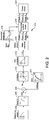
- FIG 1 is a functional block diagram depicting an uninterruptible power supply (UPS) 100.
- the uninterruptible power supply 100 includes power conversion circuitry such as a circuit breaker/filter 105, a rectifier 110, a control switch 115, a controller 120, a backup power source 125, an inverter 130, a transformer such as an isolation transformer 135, and a bypass switch 140.
- the uninterruptible power supply 100 also includes at least one input 145 and output 150.
- the input 145 couples an AC power source 155 (e.g., grid power) with the uninterruptible power supply 100 and the output 150 couples the uninterruptable power supply 100 with a load.
- AC power source 155 e.g., grid power
- the circuit breaker/filter 105 receives power from the AC power source 155 via the input 145, filters the input power, and provides filtered power to the rectifier 110.
- the AC power source 155 provides three-phase AC power.
- the rectifier 110 rectifies the filtered power, and provides rectified power to the control switch 115.
- the control switch 115 receives the rectified power from the rectifier 110, and receives DC power from the backup power source 125, such as a battery or fuel cell. Under the control of the controller 120, the control switch 115 provides power from the rectifier 110 to the inverter 130.
- the controller 120 changes the state of the control switch 115 to couple the rectifier 110 with the inverter 130 when the controller 120 determines that the output power of the rectifier 110 is within a tolerance range. In some embodiments, the controller 120 determines that the output power of the rectifier 110 is outside a tolerance range, for example, during a black out or brown out condition. In this example, the controller 120 operates control of the switch 115 to provide DC power from the backup power source 125 to the inverter 130 directly or via intervening components such as the rectifier 110.
- the uninterruptible power supply 100 also provides power at the output 150 for a load via the backup power source 125 during failure of the AC power source 155. In some embodiments, the power provided by the uninterruptible power supply 100 at the output 150 is three-phase AC power.
- the inverter 130 receives DC power output from the rectifier 110 or the backup power source 125, converts the DC power to AC power, and regulates the AC power.
- the uninterruptible power supply 100 includes the isolation transformer 135, the inverter 130 provides regulated AC power to the isolation transformer 135.
- the isolation transformer 135 increases or decreases the voltage of the AC power output from the inverter 130, and provides isolation between the uninterruptible power supply 100 and a load.
- the bypass switch 140 couples the AC power source 155 or the input 145 with the output 150, bypassing at least some components of the uninterruptible power supply 100 (e.g., the rectifier 110) to provide power to the output 150 in a bypass mode of operation.
- the controller 120 controls the bypass switch 140 to operate in the bypass mode when the power quality from the AC power source 155 is within a tolerance range, or when there is a failure of the rectifier 110 or other component of the uninterruptible power supply 100.
- the UPS 100 includes one or more sensors 160 that monitor the output power.
- the sensors 160 are coupled to the output 150 and/or a DC bus of the UPS 100 and to the controller 120 to measure parameters of the output power and provide the information to the controller 120.
- the controller 120 receives information from the sensors 160 and operates the UPS 100 in various modes, depending on the parameters related to the output power.
- the parameters include measureable characteristics of the output power, including electrical characteristics such as voltage, current, power (kilowatts), and energy (kilowatt hours).
- the UPS 100 can include a control loop that determines energy drawn from the AC power source 155 and/or the backup power source 125, comparing a DC bus current level with a current reference level and adjusting needed input power.
- the UPS 100 can run in various modes depending on how much output power is being drawn. For example, the UPS 100 can be rated for a certain maximum or optimal load. In some embodiments, if the load on the UPS 100 is low relative to the rated load, the UPS 100 can use one, two, or three of the three phases of the input power.
- the controller 120 includes at least one processor or other logic device. In some embodiments, the controller 120 includes a digital signal processor (DSP). The controller 120 may also include at least one field programmable gate array (FPGA) and an application specific integrated circuit (ASIC), or other hardware, software, firmware, or combinations thereof. In various embodiments, one or more controllers may be part of the UPS 100, or external to but operatively coupled with the UPS 100. Sensor filters, as further described below, may be part of the controller 120 or a separate device that outputs data responsive, at least in part, to instructions from the controller 120. In some embodiments, the filters can be implemented in software, hardware, firmware, or combinations thereof.
- FIG. 2 shows a block diagram of an example control structure 200, which can be implemented, for example, by the controller 120 of the UPS 100.
- the control structure 200 includes a reference selector 202, which selects a reference voltage level for a DC bus of the UPS 100. For example, a user can configure the UPS to operate with different DC bus voltage levels related to 400V or 480V installations.
- the control structure 200 also includes a ramp in function 204.
- the ramp in function 204 can be used during startup of the UPS 100 so that the UPS 100 powers up smoothly with a minimum of overshoot.
- the ramp in function 204 provides the voltage reference (Vref) to an addition block 206.
- An analog-to-digital converter (ADC) 208 samples an actual voltage level of the DC bus and outputs a value of the DC bus voltage (Vdcbus).
- the Vdcbus is negated and provided to the addition block 206 to subtract the DC bus voltage from the reference voltage to calculate an error voltage (Ve).
- the error voltage is provided to a limitation block 210, which can set limits on the error voltage.
- the limits are set at values optimized by an algorithm. Alternatively or additionally, the limits can be configured by the user. Limits on the error voltage can be used, for example, to dampen the control loop or to minimize overshooting.
- the limitation block 210 provides a limited voltage error output to a regulator such as a proportional integral derivative (PID) controller 212.
- PID controller 212 receives the voltage error and generates a current reference (Iref) based on the voltage error.
- the current reference is provided to a phase selector 214, which selects a number of phases from which to draw input current based on the current reference. For example, if the current reference is below a first threshold, the phase selector 214 can select only one phase from which to draw input current for the UPS 100. If the current reference is above the first threshold but below a second threshold, the phase selector 214 can select two phases from which to draw input current for the UPS 100.
- the selected phases are input to a sinusoidal current shaper 216, which shapes the input current so that the input current is phase corrected.
- the sinusoidal current shaper 216 also receives a sinusoidal reference from a sinusoidal reference generator 218 with which the sinusoidal current shaper 216 multiplies the current reference to shape the input current so that the input current is phase corrected.
- the sinusoidal current shaper 216 outputs the phase-corrected current reference to a power circuit 220, which generates an output current based on the current reference.
- the power circuit 220 can include insulated gate bipolar transistors (IGBTs) and/or metal oxide semiconductor field effect transistors (MOSFETs) to generate the output current.
- IGBTs insulated gate bipolar transistors
- MOSFETs metal oxide semiconductor field effect transistors
- FIG. 3 shows a flow chart of an example process 300, which can be implemented by the control structure 200 of the controller 120.
- the process 300 starts with an error voltage being calculated at stage 302.
- the error voltage can be calculated as described above, by comparing a measured voltage on the DC bus to a voltage reference.
- a current regulator algorithm is run, which generates a current reference based on the error voltage.
- the current reference is compared to a current limit. If the current reference is greater than the current limit, current can be added from a backup power source, such as one or more batteries of the UPS.
- the current reference is compared to a first threshold.
- the first threshold can be 5% of the rated load for the UPS. If the current reference is below the 5% load level, at stage 310, only one phase is used to draw input AC power. The process 300 can then restart, continuing to monitor for changes in the power drawn by the load.
- the current reference can be compared to a second threshold.
- the second threshold can be 10% of the rated load of the UPS. If the current reference is below the 10% load level, at stage 415, two phases are used to draw input AC power. The process 300 can then restart, continuing to monitor for changes in the power drawn by the load.
- the process 300 can then restart and continue to monitor the power drawn by the load, which can be determined by the error voltage calculation 302.
- the example transfer points of 5% and 10% of the rated load can also include incorporate a hysteresis (e.g., 1%) to avoid toggling between phase operations at the threshold points. Further, other values may be used for the transfer points in different embodiments.
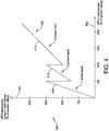
- FIG. 4 is a graph 400 of an example transition from one-phase to three-phase operation of the UPS.
- the graph 400 shows load on each phase 404 measured as a percentage of system rating, as a function of output power 402, also measured as a percentage of system rating.
- a percentage load plot 406 includes a first section 408, where the UPS is drawing power from one phase. As the output power 402 increases from 0% to 5% of the rated load, the load on the one phase 404 increases from 0% to 15%, as the UPS is operating in a one-phase in, three-phase out mode. Thus, the load on the one phase 404 is three times the output power 402.
- the UPS transitions to draw power from two phases, operating in a two-phase in, three-phase out mode.
- a second section 410 of the percentage load plot 406 shows the load on each of the two phases 404 decreases initially to 7.5% as the second phase shares the load of the one phase, and then increases to 15% as the output power 402 increases to 10%.
- the load on each phase 402 is approximately 1.5 times the output power 402, but will be a little higher due to losses in the UPS.
- a third section 412 of the percentage load plot 406 shows the load on each of the three phases 404 decrease initially to 10% and then increase linearly with the output power 402. As three phases of input current are drawn upon to supply power to three phases of output current, the load on each phase 404 approximately equal to the output power 402.
- FIG. 5 is a block diagram 500 showing example portions of the UPS 100.
- the UPS 100 includes an input 502 receiving three-phase power, for example, from a utility.
- the UPS 100 includes first, second, and third PFC circuits 504, 506, 508, each receiving one phase of the three-phase power.
- the PFC circuits 504, 506, 508 are coupled to the input 502 via first, second, and third mains backfeed switches 514, 516, 518.
- the switches 514, 516, 518 can be used to control the number of phases of input power that are drawn upon as described above. For example, for the UPS 100 to run in one-phase operation, the first switch 514 can be closed to draw current from the input power, while the second and third switches 516, 518 are opened.
- the PFC circuits 504, 506, 508 are connected to a bus 512.
- the bus 512 is a common DC bus, coupled to each of the PFC circuits and to first, second, and third inverters 524, 526, 528.
- the inverters 524, 526, 528 are coupled to an output 550 via first, second, and third inverter switches 534, 536, 538.
- the output 550 provides three-phase power, for example, to a load.
- Each of the inverters 524, 526, 528 provides one phase of the three phases of the output power.
- the inverters 524, 526, 528 can output three-phase power from one, two, or three-phase input power as provided by the PFC circuits 504, 506, 508 also all coupled to the bus 512.
- the UPS can draw current from one, two, or three phases of the input power based on parameters, such as a load level.
- the appropriate mains backfeed switches 514, 516, 518 can be opened or closed to draw current from the desired number of phases.
- closing the mains backfeed switches 514, 516, 518 takes a predetermined amount of time. For example, some switches can have a delay before closing.
- a battery 510 can be used as an intermediate power source to provide power to the load until the switch closes.
- the battery 510 can be coupled to the output 550 and/or to the DC bus 512 and drawn upon for current as needed.
- the load level can also be affected by an operating mode of the UPS. For example, if the UPS is running in bypass mode, the load level on the output of the UPS can be higher than a threshold, but the load level on certain components (e.g., the PFC and/or the inverter) of the UPS can be below the threshold, and the UPS can run in one-phase mode. While the examples above have discussed load level as a parameter for determining the number of phases for drawing input power, other parameters of the input and/or output power can also be used.
Description
- At least one embodiment of the present invention relates generally to control of an uninterruptible power supply.
- Uninterruptible power supplies (UPSs) are used to provide reliable power to many different types of electronic equipment. Uninterruptible power supplies regulate power provided to a load, and can provide backup power to a load in the event of a loss of primary power, such as during black out or brown out conditions. Some power can be lost in the providing of power by the UPS. The less power that is lost, the more efficiently the UPS can provide power to electronic equipment. Document
DE 102012100673 A1 discloses to redistribute the power between three input phases in order to balance the power between the three phases. - According to the present invention, an uninterruptible power supply according to
claim 1 is provided. - In some embodiments, the one or more parameters include a percentage load drawn on the uninterruptible power supply, relative to a rated load.
- In some embodiments, the power conversion circuit includes a bus, and the one or more parameters include a measured voltage on the bus.
- In some embodiments, the one or more parameters include a current reference of the controller.
- In some embodiments, the output is configured to provide output power having three phases.
- In some embodiments, the controller is configured to determine that the value of the one or more parameters is less than a first threshold and based on the comparison, select one as the number of phases of the input power for receiving power for the power conversion circuit.
- In some embodiments, the controller is configured to determine that the value of the one or more parameters is greater than a first threshold and less than a second threshold and based on the comparison, select two as the number of phases of the input power for receiving power for the power conversion circuit.
- In some embodiments, the controller is configured to determine that the value of the one or more parameters is greater than a second threshold and based on the comparison, select three as the number of phases of the input power for receiving power for the power conversion circuit.
- In some embodiments, the uninterruptible power supply further includes a battery coupled to the output and configured to provide power to the output during a changing of the selection of the number of phases of the input power.
- According to the present invention, a method for controlling an uniterruptible power supply according to claim 8 is provided.
- The accompanying drawings are not intended to be drawn to scale. In the drawings, each identical or nearly identical component that is illustrated in various figures is represented by a like numeral. For purposes of clarity, not every component may be labeled in every drawing. In the drawings:
-
FIG. 1 is a functional block diagram depicting an example uninterruptible power supply in accordance with an embodiment; -
FIG. 2 is a functional block diagram of an example control structure of an uninterruptible power supply in accordance with an embodiment; -
FIG. 3 is a flow chart showing an example process in accordance with an embodiment; -
FIG. 4 is a graph showing an example load on phases of an uninterruptible power supply in accordance with an embodiment; and -
FIG. 5 is a functional block diagram of an example portion of an uninterruptible power supply in accordance with an embodiment. - An uninterruptible power supply (UPS) can operate in different modes depending on the load level on the UPS. For example, if there is no load on the UPS or the UPS is running in a bypass mode (or eco-mode), elements of the UPS may still be running at a low level while not supporting a load. The elements may continue to run so that the UPS can be ready to support the load in the event of a transfer from bypass mode or in the event of a change in the load level. While the power used to run the elements at a low level can be minimal, less power can be used if fewer elements are kept running. In some embodiments, the UPS is a three-phase UPS and will operate using only one of the three input phases in certain situations, such as when there is no load, low load, or the UPS is running in bypass mode. The UPS can ramp up from one to two to three phases as needed, depending on the load. By operating from less than all three phases when elements of the UPS are not supporting the load, less power can be lost and the UPS can run more efficiently. In some embodiments, the UPS includes an algorithm to transition from operating from one phase to three phases.
- Examples of the methods and apparatuses discussed herein are not limited in application to the details of construction and the arrangement of components set forth in the following description or illustrated in the accompanying drawings. The methods and apparatuses are capable of implementation in other examples and of being practiced or of being carried out in various ways. Examples of specific implementations are provided herein for illustrative purposes only and are not intended to be limiting. In particular, acts, components, elements and features discussed in connection with any one or more examples are not intended to be excluded from a similar role in any other examples.
- Also, the phraseology and terminology used herein is for the purpose of description and should not be regarded as limiting. Any references to examples, components, elements or acts of the systems and methods herein referred to in the singular may also embrace examples including a plurality, and any references in plural to any example, component, element or act herein may also embrace examples including only a singularity. References in the singular or plural form are not intended to limit the presently disclosed systems or methods, their components, acts, or elements. The use herein of "including," "comprising," "having," "containing," "involving," and variations thereof is meant to encompass the items listed thereafter and equivalents thereof as well as additional items. References to "or" may be construed as inclusive so that any terms described using "or" may indicate any of a single, more than one, and all of the described terms.
-
FIG 1 is a functional block diagram depicting an uninterruptible power supply (UPS) 100. Theuninterruptible power supply 100 includes power conversion circuitry such as a circuit breaker/filter 105, arectifier 110, acontrol switch 115, acontroller 120, abackup power source 125, aninverter 130, a transformer such as anisolation transformer 135, and abypass switch 140. Theuninterruptible power supply 100 also includes at least oneinput 145 andoutput 150. Theinput 145 couples an AC power source 155 (e.g., grid power) with theuninterruptible power supply 100 and theoutput 150 couples theuninterruptable power supply 100 with a load. - In one embodiment, the circuit breaker/
filter 105 receives power from theAC power source 155 via theinput 145, filters the input power, and provides filtered power to therectifier 110. In some embodiments, theAC power source 155 provides three-phase AC power. Therectifier 110 rectifies the filtered power, and provides rectified power to thecontrol switch 115. Thecontrol switch 115 receives the rectified power from therectifier 110, and receives DC power from thebackup power source 125, such as a battery or fuel cell. Under the control of thecontroller 120, thecontrol switch 115 provides power from therectifier 110 to theinverter 130. For example, thecontroller 120 changes the state of thecontrol switch 115 to couple therectifier 110 with theinverter 130 when thecontroller 120 determines that the output power of therectifier 110 is within a tolerance range. In some embodiments, thecontroller 120 determines that the output power of therectifier 110 is outside a tolerance range, for example, during a black out or brown out condition. In this example, thecontroller 120 operates control of theswitch 115 to provide DC power from thebackup power source 125 to theinverter 130 directly or via intervening components such as therectifier 110. Theuninterruptible power supply 100 also provides power at theoutput 150 for a load via thebackup power source 125 during failure of theAC power source 155. In some embodiments, the power provided by theuninterruptible power supply 100 at theoutput 150 is three-phase AC power. - The
inverter 130 receives DC power output from therectifier 110 or thebackup power source 125, converts the DC power to AC power, and regulates the AC power. In some embodiments where theuninterruptible power supply 100 includes theisolation transformer 135, theinverter 130 provides regulated AC power to theisolation transformer 135. The isolation transformer 135 increases or decreases the voltage of the AC power output from theinverter 130, and provides isolation between theuninterruptible power supply 100 and a load. - In some embodiments, the
bypass switch 140 couples theAC power source 155 or theinput 145 with theoutput 150, bypassing at least some components of the uninterruptible power supply 100 (e.g., the rectifier 110) to provide power to theoutput 150 in a bypass mode of operation. For example, thecontroller 120 controls thebypass switch 140 to operate in the bypass mode when the power quality from theAC power source 155 is within a tolerance range, or when there is a failure of therectifier 110 or other component of theuninterruptible power supply 100. - In some embodiments, the
UPS 100 includes one ormore sensors 160 that monitor the output power. Thesensors 160 are coupled to theoutput 150 and/or a DC bus of theUPS 100 and to thecontroller 120 to measure parameters of the output power and provide the information to thecontroller 120. Thecontroller 120 receives information from thesensors 160 and operates theUPS 100 in various modes, depending on the parameters related to the output power. The parameters include measureable characteristics of the output power, including electrical characteristics such as voltage, current, power (kilowatts), and energy (kilowatt hours). For example, theUPS 100 can include a control loop that determines energy drawn from theAC power source 155 and/or thebackup power source 125, comparing a DC bus current level with a current reference level and adjusting needed input power. TheUPS 100 can run in various modes depending on how much output power is being drawn. For example, theUPS 100 can be rated for a certain maximum or optimal load. In some embodiments, if the load on theUPS 100 is low relative to the rated load, theUPS 100 can use one, two, or three of the three phases of the input power. - In some embodiments, the
controller 120 includes at least one processor or other logic device. In some embodiments, thecontroller 120 includes a digital signal processor (DSP). Thecontroller 120 may also include at least one field programmable gate array (FPGA) and an application specific integrated circuit (ASIC), or other hardware, software, firmware, or combinations thereof. In various embodiments, one or more controllers may be part of theUPS 100, or external to but operatively coupled with theUPS 100. Sensor filters, as further described below, may be part of thecontroller 120 or a separate device that outputs data responsive, at least in part, to instructions from thecontroller 120. In some embodiments, the filters can be implemented in software, hardware, firmware, or combinations thereof. -
FIG. 2 shows a block diagram of anexample control structure 200, which can be implemented, for example, by thecontroller 120 of theUPS 100. In some embodiments, thecontrol structure 200 includes areference selector 202, which selects a reference voltage level for a DC bus of theUPS 100. For example, a user can configure the UPS to operate with different DC bus voltage levels related to 400V or 480V installations. Thecontrol structure 200 also includes a ramp infunction 204. The ramp infunction 204 can be used during startup of theUPS 100 so that theUPS 100 powers up smoothly with a minimum of overshoot. The ramp infunction 204 provides the voltage reference (Vref) to anaddition block 206. An analog-to-digital converter (ADC) 208 samples an actual voltage level of the DC bus and outputs a value of the DC bus voltage (Vdcbus). The Vdcbus is negated and provided to theaddition block 206 to subtract the DC bus voltage from the reference voltage to calculate an error voltage (Ve). The error voltage is provided to alimitation block 210, which can set limits on the error voltage. In some embodiments, the limits are set at values optimized by an algorithm. Alternatively or additionally, the limits can be configured by the user. Limits on the error voltage can be used, for example, to dampen the control loop or to minimize overshooting. - The
limitation block 210 provides a limited voltage error output to a regulator such as a proportional integral derivative (PID)controller 212. ThePID controller 212 receives the voltage error and generates a current reference (Iref) based on the voltage error. The current reference is provided to aphase selector 214, which selects a number of phases from which to draw input current based on the current reference. For example, if the current reference is below a first threshold, thephase selector 214 can select only one phase from which to draw input current for theUPS 100. If the current reference is above the first threshold but below a second threshold, thephase selector 214 can select two phases from which to draw input current for theUPS 100. The selected phases are input to a sinusoidalcurrent shaper 216, which shapes the input current so that the input current is phase corrected. The sinusoidalcurrent shaper 216 also receives a sinusoidal reference from asinusoidal reference generator 218 with which the sinusoidalcurrent shaper 216 multiplies the current reference to shape the input current so that the input current is phase corrected. The sinusoidalcurrent shaper 216 outputs the phase-corrected current reference to apower circuit 220, which generates an output current based on the current reference. Thepower circuit 220 can include insulated gate bipolar transistors (IGBTs) and/or metal oxide semiconductor field effect transistors (MOSFETs) to generate the output current. - The transitions from drawing power from one phase to two phases and/or drawing power from two phases to three phases can include an algorithm to determine points of transfer and/or a ramping up from one phase to three phases, as well as ramping down from three phases to two and from two phases to one. For example,
FIG. 3 shows a flow chart of anexample process 300, which can be implemented by thecontrol structure 200 of thecontroller 120. In some embodiments, theprocess 300 starts with an error voltage being calculated atstage 302. The error voltage can be calculated as described above, by comparing a measured voltage on the DC bus to a voltage reference. Atstage 304, a current regulator algorithm is run, which generates a current reference based on the error voltage. Atstage 306, the current reference is compared to a current limit. If the current reference is greater than the current limit, current can be added from a backup power source, such as one or more batteries of the UPS. - At
stage 308, the current reference is compared to a first threshold. For example, the first threshold can be 5% of the rated load for the UPS. If the current reference is below the 5% load level, atstage 310, only one phase is used to draw input AC power. Theprocess 300 can then restart, continuing to monitor for changes in the power drawn by the load. - If the current reference is above the first threshold, at
stage 312, the current reference can be compared to a second threshold. For example, the second threshold can be 10% of the rated load of the UPS. If the current reference is below the 10% load level, at stage 415, two phases are used to draw input AC power. Theprocess 300 can then restart, continuing to monitor for changes in the power drawn by the load. - If the current reference is above the second threshold, at
stage 316, all three phases can be used to draw input AC power. Theprocess 300 can then restart and continue to monitor the power drawn by the load, which can be determined by theerror voltage calculation 302. The example transfer points of 5% and 10% of the rated load can also include incorporate a hysteresis (e.g., 1%) to avoid toggling between phase operations at the threshold points. Further, other values may be used for the transfer points in different embodiments. -
FIG. 4 is agraph 400 of an example transition from one-phase to three-phase operation of the UPS. Thegraph 400 shows load on eachphase 404 measured as a percentage of system rating, as a function ofoutput power 402, also measured as a percentage of system rating. Apercentage load plot 406 includes afirst section 408, where the UPS is drawing power from one phase. As theoutput power 402 increases from 0% to 5% of the rated load, the load on the onephase 404 increases from 0% to 15%, as the UPS is operating in a one-phase in, three-phase out mode. Thus, the load on the onephase 404 is three times theoutput power 402. - As the
output power 402 exceeds the first threshold, the UPS transitions to draw power from two phases, operating in a two-phase in, three-phase out mode. Asecond section 410 of thepercentage load plot 406 shows the load on each of the twophases 404 decreases initially to 7.5% as the second phase shares the load of the one phase, and then increases to 15% as theoutput power 402 increases to 10%. As the two phases are drawn upon to supply power for three phases, the load on eachphase 402 is approximately 1.5 times theoutput power 402, but will be a little higher due to losses in the UPS. - As the
output power 402 exceeds the second threshold, the UPS transitions to draw power from all three phases, operating in a three-phase in, three-phase out mode. Athird section 412 of thepercentage load plot 406 shows the load on each of the threephases 404 decrease initially to 10% and then increase linearly with theoutput power 402. As three phases of input current are drawn upon to supply power to three phases of output current, the load on eachphase 404 approximately equal to theoutput power 402. -
FIG. 5 is a block diagram 500 showing example portions of theUPS 100. In some embodiments, theUPS 100 includes aninput 502 receiving three-phase power, for example, from a utility. TheUPS 100 includes first, second, andthird PFC circuits PFC circuits input 502 via first, second, and third mains backfeedswitches switches UPS 100 to run in one-phase operation, thefirst switch 514 can be closed to draw current from the input power, while the second andthird switches - The
PFC circuits third inverters inverters output 550 via first, second, and third inverter switches 534, 536, 538. Theoutput 550 provides three-phase power, for example, to a load. Each of theinverters inverters inverters PFC circuits - As described above, the UPS can draw current from one, two, or three phases of the input power based on parameters, such as a load level. As phases are ramped in, the appropriate mains backfeed
switches switches battery 510 can be used as an intermediate power source to provide power to the load until the switch closes. Thebattery 510 can be coupled to theoutput 550 and/or to the DC bus 512 and drawn upon for current as needed. - The load level can also be affected by an operating mode of the UPS. For example, if the UPS is running in bypass mode, the load level on the output of the UPS can be higher than a threshold, but the load level on certain components (e.g., the PFC and/or the inverter) of the UPS can be below the threshold, and the UPS can run in one-phase mode. While the examples above have discussed load level as a parameter for determining the number of phases for drawing input power, other parameters of the input and/or output power can also be used.
- Having thus described several aspects of at least one embodiment of this invention, it is to be appreciated various alterations, modifications, and improvements will readily occur to those skilled in the art. Accordingly, the foregoing description and drawings are by way of example only.
Claims (15)
- An uninterruptible power supply (100), comprising:an input (145) configured to receive input power having three phases;an output (150) configured to provide output power;power conversion circuitry (105) coupled with the input and the output;one or more sensors configured to monitor one or more parameters indicative of a value of the output power; anda controller (120) coupled with the power conversion circuitry and the one or more sensors, the controller configured to:receive, from the one or more sensors, values for the one or more parameters; andbased on the values for the one or more parameters, reduce a number of phases of the input power provided to the power conversion circuitry to at least one.
- The uninterruptible power supply (100) of claim 1, wherein the one or more parameters comprise at least one of a percentage load drawn on the uninterruptible power supply, relative to a rated load and a current reference of the controller.
- The uninterruptible power supply (100) of claim 1, wherein the power conversion circuitry (105) comprises a bus, and the one or more parameters comprise a measured voltage on the bus.
- The uninterruptible power supply (100) of claim 1, wherein the controller (120) is configured to:determine that a value of at least one of the one or more parameters is less than a first threshold; andbased on the comparison, select one as the number of phases of the input power for receiving power for the power conversion circuitry (105).
- The uninterruptible power supply (100) of claim 1, wherein the controller (120) is configured to:determine that a value of at least one of the one or more parameters is greater than a first threshold and less than a second threshold; andbased on the comparison, select two as the number of phases of the input power for receiving power for the power conversion circuitry (105).
- The uninterruptible power supply (100) of claim 1, wherein the controller (120) is configured to:after having reduced the number of phases of the input power to at least one, determine that a value of at least one of the one or more parameters is greater than a second threshold; andbased on the comparison, select three as the number of phases of the input power for receiving power for the power conversion circuitry (105).
- The uninterruptible power supply (100) of claim 1 further comprising a battery (125) coupled to the output (150) and configured to provide power to the output during a changing of the reduction of the number of phases of the input power.
- A method for controlling an uninterruptible power supply (100) comprising an input (145) configured to receive input power having three phases, an output (150) configured to provide output power, power conversion circuitry (105) coupled with the input and the output, and a controller coupled with the power conversion circuitry, the method comprising:receiving values for one or more parameters indicative of a value of the output power; andbased on the values for the one or more parameters, reducing a number of phases of the input power provided to the power conversion circuitry to at least one.
- The method of claim 8, wherein the one or more parameters comprise a percentage load drawn on the uninterruptible power supply, relative to a rated load.
- The method of claim 8, wherein the power conversion circuitry (105) comprises a bus, and the one or more parameters comprise a measured current on the bus.
- The method of claim 8, wherein the one or more parameters comprise a current reference of the controller (120).
- The method of claim 8 comprising:determining that the value of the one or more parameters is less than a first threshold; andbased on the comparison, selecting one as the number of phases of the input power for receiving power for the power conversion circuitry (105).
- The method of claim 8 comprising:determining that a value of at least one of the one or more parameters is greater than a first threshold and less than a second threshold; andbased on the comparison, selecting two as the number of phases of the input power for receiving power for the power conversion circuitry (105).
- The method of claim 8 comprising:after having reduced the number of phases of the input power to at least one, determining that a value of at least one of the one or more parameters is greater than a second threshold; andbased on the comparison, selecting three as the number of phases of the input power for receiving power for the power conversion circuitry (105).
- The method of claim 8, wherein the uninterruptible power supply (100) further comprises a battery (125) coupled to the output (150) and the method further comprises providing power to the output during a changing of the reduction of the number of phases of the input power.
Applications Claiming Priority (1)
| Application Number | Priority Date | Filing Date | Title |
|---|---|---|---|
| PCT/US2013/053446 WO2015016944A1 (en) | 2013-08-02 | 2013-08-02 | Uninterruptible power supply control |
Publications (3)
| Publication Number | Publication Date |
|---|---|
| EP3028366A1 EP3028366A1 (en) | 2016-06-08 |
| EP3028366A4 EP3028366A4 (en) | 2017-03-15 |
| EP3028366B1 true EP3028366B1 (en) | 2019-06-26 |
Family
ID=52432296
Family Applications (1)
| Application Number | Title | Priority Date | Filing Date |
|---|---|---|---|
| EP13890443.8A Active EP3028366B1 (en) | 2013-08-02 | 2013-08-02 | Uninterruptible power supply control |
Country Status (5)
| Country | Link |
|---|---|
| US (1) | US10148123B2 (en) |
| EP (1) | EP3028366B1 (en) |
| CN (1) | CN105431996B (en) |
| DK (1) | DK3028366T3 (en) |
| WO (1) | WO2015016944A1 (en) |
Families Citing this family (7)
| Publication number | Priority date | Publication date | Assignee | Title |
|---|---|---|---|---|
| KR101628525B1 (en) * | 2014-11-13 | 2016-06-09 | 현대자동차주식회사 | Apparatus for charging battery of vehicle |
| US10637279B2 (en) * | 2017-02-22 | 2020-04-28 | Vertiv Corporation | Method of mitigating effects of AC input voltage surge in a transformer-less rectifier uninterruptible power supply system |
| RU172897U1 (en) * | 2017-03-22 | 2017-07-31 | Открытое акционерное общество "Электровыпрямитель" | Three Phase Uninterruptible Power Supply |
| GB201709695D0 (en) | 2017-06-19 | 2017-08-02 | Eaton Power Quality Oy | Multi-mode UPS system with an improved energy saver mode and method of operation |
| US11732820B2 (en) * | 2020-10-23 | 2023-08-22 | Fisher Controls International Llc | Activating trip functions of a safety valve positioner by way of a control panel to achieve a safe state |
| US20220341998A1 (en) * | 2021-04-23 | 2022-10-27 | Schneider Electric It Corporation | Wireless monitoring and management of ups battery modules and other accessories |
| US11489362B1 (en) | 2022-03-10 | 2022-11-01 | Enconnex LLC | Uninterruptable power supply with supplemental power apportionment |
Family Cites Families (19)
| Publication number | Priority date | Publication date | Assignee | Title |
|---|---|---|---|---|
| US7269036B2 (en) * | 2003-05-12 | 2007-09-11 | Siemens Vdo Automotive Corporation | Method and apparatus for adjusting wakeup time in electrical power converter systems and transformer isolation |
| US7259477B2 (en) * | 2003-08-15 | 2007-08-21 | American Power Conversion Corporation | Uninterruptible power supply |
| US20050105229A1 (en) * | 2003-11-14 | 2005-05-19 | Ballard Power Systems Corportion | Two-level protection for uninterrupted power supply |
| JP4645808B2 (en) * | 2004-12-17 | 2011-03-09 | サンケン電気株式会社 | Three-phase power converter |
| EP2036189B1 (en) * | 2006-06-01 | 2019-04-03 | Google LLC | Data center uninterruptible power distribution architecture |
| CN101523710B (en) * | 2006-06-06 | 2014-03-05 | 威廉·亚历山大 | Universal power converter |
| US7550873B2 (en) * | 2007-01-28 | 2009-06-23 | Ming Jiang | Uninterruptible power supply for home/office networking and communication system |
| US7781914B2 (en) | 2007-08-10 | 2010-08-24 | American Power Conversion Corporation | Input and output power modules configured to provide selective power to an uninterruptible power supply |
| US7847435B2 (en) * | 2008-07-16 | 2010-12-07 | International Business Machines Corporation | Intrinsically balanced direct current uninterruptible power supply |
| US8060321B2 (en) * | 2008-08-15 | 2011-11-15 | Liebert Corporation | System and method for detecting an electrical short across a static switch of an uninterruptible power supply |
| KR20120096565A (en) * | 2009-12-01 | 2012-08-30 | 인터네셔널 일렉트리컬 세이빙스 디벨롭먼트 엘엘씨 | Systems and devices for reducing phantom load |
| US8546689B2 (en) * | 2011-02-24 | 2013-10-01 | Schneider Electric It Corporation | Service access point for a uninterruptible power supply |
| CN103534916A (en) * | 2011-03-10 | 2014-01-22 | 三菱电机株式会社 | Power conversion device |
| TWI443935B (en) * | 2011-07-13 | 2014-07-01 | Delta Electronics Inc | Uninterruptible power supply |
| CN102508542B (en) * | 2011-11-18 | 2014-11-05 | 百度在线网络技术(北京)有限公司 | Method, system and device for controlling power supply for supplying power to server in centralized way |
| DE102012100673A1 (en) | 2012-01-27 | 2013-08-01 | Changetec Gmbh | Device for supplying electrical energy from e.g. photovoltaic current generating device to low voltage-mains supply, has switching units connected to coupling units to switch coupling units between phases based on power difference quantity |
| US9041250B1 (en) * | 2012-03-15 | 2015-05-26 | Amazon Technologies, Inc. | System and method for maintaining power to electrical systems |
| CN202535279U (en) * | 2012-04-01 | 2012-11-14 | 广东易事特电源股份有限公司 | UPS power supply based on self-coupling phase-shifting transformer and double-six pulse rectification |
| CN104919385A (en) * | 2013-02-28 | 2015-09-16 | 惠普发展公司,有限责任合伙企业 | Three-phase parallel power converter load adjustment |
-
2013
- 2013-08-02 WO PCT/US2013/053446 patent/WO2015016944A1/en active Application Filing
- 2013-08-02 EP EP13890443.8A patent/EP3028366B1/en active Active
- 2013-08-02 CN CN201380078616.4A patent/CN105431996B/en active Active
- 2013-08-02 DK DK13890443.8T patent/DK3028366T3/en active
- 2013-08-02 US US14/906,402 patent/US10148123B2/en active Active
Non-Patent Citations (1)
| Title |
|---|
| None * |
Also Published As
| Publication number | Publication date |
|---|---|
| CN105431996B (en) | 2019-07-16 |
| US10148123B2 (en) | 2018-12-04 |
| CN105431996A (en) | 2016-03-23 |
| DK3028366T3 (en) | 2019-08-26 |
| WO2015016944A1 (en) | 2015-02-05 |
| EP3028366A4 (en) | 2017-03-15 |
| US20160164341A1 (en) | 2016-06-09 |
| EP3028366A1 (en) | 2016-06-08 |
Similar Documents
| Publication | Publication Date | Title |
|---|---|---|
| EP3028366B1 (en) | Uninterruptible power supply control | |
| KR101542435B1 (en) | Systems for and methods of controlling operation of a | |
| US7602627B2 (en) | Electrical power source, operational method of the same, inverter and operational method of the same | |
| US9735619B2 (en) | Power conversion device | |
| EP3069431B1 (en) | Uninterruptible power supply control | |
| WO2017106719A1 (en) | Electrical systems and related frequency regulation methods | |
| JP2018082569A (en) | System interconnection power converter and method for controlling output current of the same | |
| JP5969059B2 (en) | Power conditioner variable control device and control method for power conditioner | |
| US10033189B2 (en) | Operation control apparatus for solar power system | |
| CN111244965B (en) | Impedance compensation | |
| EP3823152A1 (en) | Power conversion system, conversion circuit control method and program | |
| US20190157903A1 (en) | Uninterruptible power supply system and uninterruptible power supply | |
| US11329488B2 (en) | Power conversion system, method for controlling converter circuit, and program | |
| EP3247018A1 (en) | Control device for inverter | |
| JP2009171652A (en) | Power conversion device | |
| EP3078107A1 (en) | Improvement of inverter regulation | |
| US20200395782A1 (en) | Power conversion device | |
| JP6849546B2 (en) | Power converter for grid interconnection | |
| JP6289123B2 (en) | Power generation system | |
| WO2020162166A1 (en) | Electric power system and power conversion device | |
| JP2018170931A (en) | Power conversion apparatus and power conversion system | |
| JP2013078237A (en) | Voltage adjusting device and voltage adjusting method | |
| JP6459923B2 (en) | Power storage system, control device, operation method | |
| RU2659811C1 (en) | Renewable sources direct current electric energy switching to the three-phase ac network method and device | |
| CN117335543A (en) | Optimized UPS power architecture for power enhanced applications |
Legal Events
| Date | Code | Title | Description |
|---|---|---|---|
| PUAI | Public reference made under article 153(3) epc to a published international application that has entered the european phase |
Free format text: ORIGINAL CODE: 0009012 |
|
| 17P | Request for examination filed |
Effective date: 20160229 |
|
| AK | Designated contracting states |
Kind code of ref document: A1 Designated state(s): AL AT BE BG CH CY CZ DE DK EE ES FI FR GB GR HR HU IE IS IT LI LT LU LV MC MK MT NL NO PL PT RO RS SE SI SK SM TR |
|
| AX | Request for extension of the european patent |
Extension state: BA ME |
|
| DAX | Request for extension of the european patent (deleted) | ||
| A4 | Supplementary search report drawn up and despatched |
Effective date: 20170209 |
|
| RIC1 | Information provided on ipc code assigned before grant |
Ipc: H02J 9/06 20060101AFI20170203BHEP |
|
| STAA | Information on the status of an ep patent application or granted ep patent |
Free format text: STATUS: EXAMINATION IS IN PROGRESS |
|
| 17Q | First examination report despatched |
Effective date: 20180625 |
|
| GRAP | Despatch of communication of intention to grant a patent |
Free format text: ORIGINAL CODE: EPIDOSNIGR1 |
|
| STAA | Information on the status of an ep patent application or granted ep patent |
Free format text: STATUS: GRANT OF PATENT IS INTENDED |
|
| INTG | Intention to grant announced |
Effective date: 20190124 |
|
| GRAS | Grant fee paid |
Free format text: ORIGINAL CODE: EPIDOSNIGR3 |
|
| GRAA | (expected) grant |
Free format text: ORIGINAL CODE: 0009210 |
|
| STAA | Information on the status of an ep patent application or granted ep patent |
Free format text: STATUS: THE PATENT HAS BEEN GRANTED |
|
| AK | Designated contracting states |
Kind code of ref document: B1 Designated state(s): AL AT BE BG CH CY CZ DE DK EE ES FI FR GB GR HR HU IE IS IT LI LT LU LV MC MK MT NL NO PL PT RO RS SE SI SK SM TR |
|
| REG | Reference to a national code |
Ref country code: GB Ref legal event code: FG4D |
|
| REG | Reference to a national code |
Ref country code: CH Ref legal event code: EP |
|
| REG | Reference to a national code |
Ref country code: AT Ref legal event code: REF Ref document number: 1149422 Country of ref document: AT Kind code of ref document: T Effective date: 20190715 |
|
| REG | Reference to a national code |
Ref country code: DE Ref legal event code: R096 Ref document number: 602013057265 Country of ref document: DE |
|
| REG | Reference to a national code |
Ref country code: IE Ref legal event code: FG4D |
|
| REG | Reference to a national code |
Ref country code: DK Ref legal event code: T3 Effective date: 20190823 |
|
| REG | Reference to a national code |
Ref country code: NL Ref legal event code: MP Effective date: 20190626 |
|
| PG25 | Lapsed in a contracting state [announced via postgrant information from national office to epo] |
Ref country code: SE Free format text: LAPSE BECAUSE OF FAILURE TO SUBMIT A TRANSLATION OF THE DESCRIPTION OR TO PAY THE FEE WITHIN THE PRESCRIBED TIME-LIMIT Effective date: 20190626 Ref country code: AL Free format text: LAPSE BECAUSE OF FAILURE TO SUBMIT A TRANSLATION OF THE DESCRIPTION OR TO PAY THE FEE WITHIN THE PRESCRIBED TIME-LIMIT Effective date: 20190626 Ref country code: LT Free format text: LAPSE BECAUSE OF FAILURE TO SUBMIT A TRANSLATION OF THE DESCRIPTION OR TO PAY THE FEE WITHIN THE PRESCRIBED TIME-LIMIT Effective date: 20190626 Ref country code: HR Free format text: LAPSE BECAUSE OF FAILURE TO SUBMIT A TRANSLATION OF THE DESCRIPTION OR TO PAY THE FEE WITHIN THE PRESCRIBED TIME-LIMIT Effective date: 20190626 Ref country code: NO Free format text: LAPSE BECAUSE OF FAILURE TO SUBMIT A TRANSLATION OF THE DESCRIPTION OR TO PAY THE FEE WITHIN THE PRESCRIBED TIME-LIMIT Effective date: 20190926 Ref country code: FI Free format text: LAPSE BECAUSE OF FAILURE TO SUBMIT A TRANSLATION OF THE DESCRIPTION OR TO PAY THE FEE WITHIN THE PRESCRIBED TIME-LIMIT Effective date: 20190626 |
|
| REG | Reference to a national code |
Ref country code: LT Ref legal event code: MG4D |
|
| PG25 | Lapsed in a contracting state [announced via postgrant information from national office to epo] |
Ref country code: GR Free format text: LAPSE BECAUSE OF FAILURE TO SUBMIT A TRANSLATION OF THE DESCRIPTION OR TO PAY THE FEE WITHIN THE PRESCRIBED TIME-LIMIT Effective date: 20190927 Ref country code: LV Free format text: LAPSE BECAUSE OF FAILURE TO SUBMIT A TRANSLATION OF THE DESCRIPTION OR TO PAY THE FEE WITHIN THE PRESCRIBED TIME-LIMIT Effective date: 20190626 Ref country code: BG Free format text: LAPSE BECAUSE OF FAILURE TO SUBMIT A TRANSLATION OF THE DESCRIPTION OR TO PAY THE FEE WITHIN THE PRESCRIBED TIME-LIMIT Effective date: 20190926 Ref country code: RS Free format text: LAPSE BECAUSE OF FAILURE TO SUBMIT A TRANSLATION OF THE DESCRIPTION OR TO PAY THE FEE WITHIN THE PRESCRIBED TIME-LIMIT Effective date: 20190626 |
|
| REG | Reference to a national code |
Ref country code: AT Ref legal event code: MK05 Ref document number: 1149422 Country of ref document: AT Kind code of ref document: T Effective date: 20190626 |
|
| PG25 | Lapsed in a contracting state [announced via postgrant information from national office to epo] |
Ref country code: NL Free format text: LAPSE BECAUSE OF FAILURE TO SUBMIT A TRANSLATION OF THE DESCRIPTION OR TO PAY THE FEE WITHIN THE PRESCRIBED TIME-LIMIT Effective date: 20190626 Ref country code: AT Free format text: LAPSE BECAUSE OF FAILURE TO SUBMIT A TRANSLATION OF THE DESCRIPTION OR TO PAY THE FEE WITHIN THE PRESCRIBED TIME-LIMIT Effective date: 20190626 Ref country code: EE Free format text: LAPSE BECAUSE OF FAILURE TO SUBMIT A TRANSLATION OF THE DESCRIPTION OR TO PAY THE FEE WITHIN THE PRESCRIBED TIME-LIMIT Effective date: 20190626 Ref country code: PT Free format text: LAPSE BECAUSE OF FAILURE TO SUBMIT A TRANSLATION OF THE DESCRIPTION OR TO PAY THE FEE WITHIN THE PRESCRIBED TIME-LIMIT Effective date: 20191028 Ref country code: SK Free format text: LAPSE BECAUSE OF FAILURE TO SUBMIT A TRANSLATION OF THE DESCRIPTION OR TO PAY THE FEE WITHIN THE PRESCRIBED TIME-LIMIT Effective date: 20190626 Ref country code: CZ Free format text: LAPSE BECAUSE OF FAILURE TO SUBMIT A TRANSLATION OF THE DESCRIPTION OR TO PAY THE FEE WITHIN THE PRESCRIBED TIME-LIMIT Effective date: 20190626 Ref country code: RO Free format text: LAPSE BECAUSE OF FAILURE TO SUBMIT A TRANSLATION OF THE DESCRIPTION OR TO PAY THE FEE WITHIN THE PRESCRIBED TIME-LIMIT Effective date: 20190626 |
|
| PG25 | Lapsed in a contracting state [announced via postgrant information from national office to epo] |
Ref country code: ES Free format text: LAPSE BECAUSE OF FAILURE TO SUBMIT A TRANSLATION OF THE DESCRIPTION OR TO PAY THE FEE WITHIN THE PRESCRIBED TIME-LIMIT Effective date: 20190626 Ref country code: IT Free format text: LAPSE BECAUSE OF FAILURE TO SUBMIT A TRANSLATION OF THE DESCRIPTION OR TO PAY THE FEE WITHIN THE PRESCRIBED TIME-LIMIT Effective date: 20190626 Ref country code: SM Free format text: LAPSE BECAUSE OF FAILURE TO SUBMIT A TRANSLATION OF THE DESCRIPTION OR TO PAY THE FEE WITHIN THE PRESCRIBED TIME-LIMIT Effective date: 20190626 Ref country code: IS Free format text: LAPSE BECAUSE OF FAILURE TO SUBMIT A TRANSLATION OF THE DESCRIPTION OR TO PAY THE FEE WITHIN THE PRESCRIBED TIME-LIMIT Effective date: 20191026 |
|
| PG25 | Lapsed in a contracting state [announced via postgrant information from national office to epo] |
Ref country code: TR Free format text: LAPSE BECAUSE OF FAILURE TO SUBMIT A TRANSLATION OF THE DESCRIPTION OR TO PAY THE FEE WITHIN THE PRESCRIBED TIME-LIMIT Effective date: 20190626 |
|
| PG25 | Lapsed in a contracting state [announced via postgrant information from national office to epo] |
Ref country code: PL Free format text: LAPSE BECAUSE OF FAILURE TO SUBMIT A TRANSLATION OF THE DESCRIPTION OR TO PAY THE FEE WITHIN THE PRESCRIBED TIME-LIMIT Effective date: 20190626 |
|
| PG25 | Lapsed in a contracting state [announced via postgrant information from national office to epo] |
Ref country code: LU Free format text: LAPSE BECAUSE OF NON-PAYMENT OF DUE FEES Effective date: 20190802 Ref country code: IS Free format text: LAPSE BECAUSE OF FAILURE TO SUBMIT A TRANSLATION OF THE DESCRIPTION OR TO PAY THE FEE WITHIN THE PRESCRIBED TIME-LIMIT Effective date: 20200224 Ref country code: LI Free format text: LAPSE BECAUSE OF NON-PAYMENT OF DUE FEES Effective date: 20190831 Ref country code: CH Free format text: LAPSE BECAUSE OF NON-PAYMENT OF DUE FEES Effective date: 20190831 Ref country code: MC Free format text: LAPSE BECAUSE OF FAILURE TO SUBMIT A TRANSLATION OF THE DESCRIPTION OR TO PAY THE FEE WITHIN THE PRESCRIBED TIME-LIMIT Effective date: 20190626 |
|
| REG | Reference to a national code |
Ref country code: BE Ref legal event code: MM Effective date: 20190831 |
|
| REG | Reference to a national code |
Ref country code: DE Ref legal event code: R097 Ref document number: 602013057265 Country of ref document: DE |
|
| PLBE | No opposition filed within time limit |
Free format text: ORIGINAL CODE: 0009261 |
|
| STAA | Information on the status of an ep patent application or granted ep patent |
Free format text: STATUS: NO OPPOSITION FILED WITHIN TIME LIMIT |
|
| PG2D | Information on lapse in contracting state deleted |
Ref country code: IS |
|
| PG25 | Lapsed in a contracting state [announced via postgrant information from national office to epo] |
Ref country code: IE Free format text: LAPSE BECAUSE OF NON-PAYMENT OF DUE FEES Effective date: 20190802 |
|
| 26N | No opposition filed |
Effective date: 20200603 |
|
| PG25 | Lapsed in a contracting state [announced via postgrant information from national office to epo] |
Ref country code: SI Free format text: LAPSE BECAUSE OF FAILURE TO SUBMIT A TRANSLATION OF THE DESCRIPTION OR TO PAY THE FEE WITHIN THE PRESCRIBED TIME-LIMIT Effective date: 20190626 Ref country code: BE Free format text: LAPSE BECAUSE OF NON-PAYMENT OF DUE FEES Effective date: 20190831 |
|
| PG25 | Lapsed in a contracting state [announced via postgrant information from national office to epo] |
Ref country code: CY Free format text: LAPSE BECAUSE OF FAILURE TO SUBMIT A TRANSLATION OF THE DESCRIPTION OR TO PAY THE FEE WITHIN THE PRESCRIBED TIME-LIMIT Effective date: 20190626 |
|
| PG25 | Lapsed in a contracting state [announced via postgrant information from national office to epo] |
Ref country code: HU Free format text: LAPSE BECAUSE OF FAILURE TO SUBMIT A TRANSLATION OF THE DESCRIPTION OR TO PAY THE FEE WITHIN THE PRESCRIBED TIME-LIMIT; INVALID AB INITIO Effective date: 20130802 Ref country code: MT Free format text: LAPSE BECAUSE OF FAILURE TO SUBMIT A TRANSLATION OF THE DESCRIPTION OR TO PAY THE FEE WITHIN THE PRESCRIBED TIME-LIMIT Effective date: 20190626 |
|
| PG25 | Lapsed in a contracting state [announced via postgrant information from national office to epo] |
Ref country code: MK Free format text: LAPSE BECAUSE OF FAILURE TO SUBMIT A TRANSLATION OF THE DESCRIPTION OR TO PAY THE FEE WITHIN THE PRESCRIBED TIME-LIMIT Effective date: 20190626 |
|
| PGFP | Annual fee paid to national office [announced via postgrant information from national office to epo] |
Ref country code: GB Payment date: 20230822 Year of fee payment: 11 |
|
| PGFP | Annual fee paid to national office [announced via postgrant information from national office to epo] |
Ref country code: FR Payment date: 20230824 Year of fee payment: 11 Ref country code: DK Payment date: 20230824 Year of fee payment: 11 Ref country code: DE Payment date: 20230828 Year of fee payment: 11 |