EP3027260B1 - Interlocking needle hub and catheter hub actuator to increase rigidity of iv catheter assembly - Google Patents
Interlocking needle hub and catheter hub actuator to increase rigidity of iv catheter assembly Download PDFInfo
- Publication number
- EP3027260B1 EP3027260B1 EP14747780.6A EP14747780A EP3027260B1 EP 3027260 B1 EP3027260 B1 EP 3027260B1 EP 14747780 A EP14747780 A EP 14747780A EP 3027260 B1 EP3027260 B1 EP 3027260B1
- Authority
- EP
- European Patent Office
- Prior art keywords
- hub
- actuator
- catheter
- needle
- channels
- Prior art date
- Legal status (The legal status is an assumption and is not a legal conclusion. Google has not performed a legal analysis and makes no representation as to the accuracy of the status listed.)
- Active
Links
Images






Classifications
-
- A—HUMAN NECESSITIES
- A61—MEDICAL OR VETERINARY SCIENCE; HYGIENE
- A61M—DEVICES FOR INTRODUCING MEDIA INTO, OR ONTO, THE BODY; DEVICES FOR TRANSDUCING BODY MEDIA OR FOR TAKING MEDIA FROM THE BODY; DEVICES FOR PRODUCING OR ENDING SLEEP OR STUPOR
- A61M25/00—Catheters; Hollow probes
- A61M25/01—Introducing, guiding, advancing, emplacing or holding catheters
- A61M25/06—Body-piercing guide needles or the like
- A61M25/0606—"Over-the-needle" catheter assemblies, e.g. I.V. catheters
-
- A—HUMAN NECESSITIES
- A61—MEDICAL OR VETERINARY SCIENCE; HYGIENE
- A61M—DEVICES FOR INTRODUCING MEDIA INTO, OR ONTO, THE BODY; DEVICES FOR TRANSDUCING BODY MEDIA OR FOR TAKING MEDIA FROM THE BODY; DEVICES FOR PRODUCING OR ENDING SLEEP OR STUPOR
- A61M25/00—Catheters; Hollow probes
- A61M25/0067—Catheters; Hollow probes characterised by the distal end, e.g. tips
- A61M25/008—Strength or flexibility characteristics of the catheter tip
-
- A—HUMAN NECESSITIES
- A61—MEDICAL OR VETERINARY SCIENCE; HYGIENE
- A61M—DEVICES FOR INTRODUCING MEDIA INTO, OR ONTO, THE BODY; DEVICES FOR TRANSDUCING BODY MEDIA OR FOR TAKING MEDIA FROM THE BODY; DEVICES FOR PRODUCING OR ENDING SLEEP OR STUPOR
- A61M25/00—Catheters; Hollow probes
- A61M25/0097—Catheters; Hollow probes characterised by the hub
-
- A—HUMAN NECESSITIES
- A61—MEDICAL OR VETERINARY SCIENCE; HYGIENE
- A61M—DEVICES FOR INTRODUCING MEDIA INTO, OR ONTO, THE BODY; DEVICES FOR TRANSDUCING BODY MEDIA OR FOR TAKING MEDIA FROM THE BODY; DEVICES FOR PRODUCING OR ENDING SLEEP OR STUPOR
- A61M25/00—Catheters; Hollow probes
- A61M25/01—Introducing, guiding, advancing, emplacing or holding catheters
- A61M25/06—Body-piercing guide needles or the like
- A61M25/0612—Devices for protecting the needle; Devices to help insertion of the needle, e.g. wings or holders
- A61M25/0618—Devices for protecting the needle; Devices to help insertion of the needle, e.g. wings or holders having means for protecting only the distal tip of the needle, e.g. a needle guard
- A61M25/0625—Devices for protecting the needle; Devices to help insertion of the needle, e.g. wings or holders having means for protecting only the distal tip of the needle, e.g. a needle guard with a permanent connection to the needle hub, e.g. a guiding rail, a locking mechanism or a guard advancement mechanism
-
- A—HUMAN NECESSITIES
- A61—MEDICAL OR VETERINARY SCIENCE; HYGIENE
- A61M—DEVICES FOR INTRODUCING MEDIA INTO, OR ONTO, THE BODY; DEVICES FOR TRANSDUCING BODY MEDIA OR FOR TAKING MEDIA FROM THE BODY; DEVICES FOR PRODUCING OR ENDING SLEEP OR STUPOR
- A61M39/00—Tubes, tube connectors, tube couplings, valves, access sites or the like, specially adapted for medical use
- A61M39/22—Valves or arrangement of valves
- A61M2039/226—Spindles or actuating means
-
- A—HUMAN NECESSITIES
- A61—MEDICAL OR VETERINARY SCIENCE; HYGIENE
- A61M—DEVICES FOR INTRODUCING MEDIA INTO, OR ONTO, THE BODY; DEVICES FOR TRANSDUCING BODY MEDIA OR FOR TAKING MEDIA FROM THE BODY; DEVICES FOR PRODUCING OR ENDING SLEEP OR STUPOR
- A61M2205/00—General characteristics of the apparatus
- A61M2205/10—General characteristics of the apparatus with powered movement mechanisms
-
- A—HUMAN NECESSITIES
- A61—MEDICAL OR VETERINARY SCIENCE; HYGIENE
- A61M—DEVICES FOR INTRODUCING MEDIA INTO, OR ONTO, THE BODY; DEVICES FOR TRANSDUCING BODY MEDIA OR FOR TAKING MEDIA FROM THE BODY; DEVICES FOR PRODUCING OR ENDING SLEEP OR STUPOR
- A61M25/00—Catheters; Hollow probes
- A61M25/01—Introducing, guiding, advancing, emplacing or holding catheters
- A61M25/06—Body-piercing guide needles or the like
- A61M25/0612—Devices for protecting the needle; Devices to help insertion of the needle, e.g. wings or holders
- A61M25/0631—Devices for protecting the needle; Devices to help insertion of the needle, e.g. wings or holders having means for fully covering the needle after its withdrawal, e.g. needle being withdrawn inside the handle or a cover being advanced over the needle
Definitions
- the present invention relates generally to intravenous (IV) catheter assemblies and particularly to increasing the rigidity between a catheter hub and a needle shield of the assembly to facilitate the threading of the catheter.
- IV intravenous
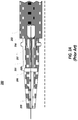
- Figure 1 illustrates a common IV catheter assembly 100 that consists of a catheter hub 101 and a needle shield 103.
- Needle shield 103 contains a needle hub from which a needle 102 extends. Needle 102 extends through catheter hub 101 and is used to thread the catheter into the vasculature of a patient.
- IV catheter assembly 100 is initially handled by a clinician as a single component. The clinician inserts needle 102 into the patient's vasculature and then slides the catheter over top of the needle further into the vasculature. Once the catheter is placed appropriately in the vasculature, needle 102 can be retracted into needle shield 103. Then, needle shield 103 can be detached from catheter hub 101 leaving catheter hub 101 for connection of other devices for blood draw or fluid injection.
- needle shield 103 and catheter hub 101 are separate components, a certain amount of flexibility may exist between the two components. If this amount of flexibility is too great, the clinician may experience difficulty when inserting needle 102 into the patient's vasculature.
- catheter hub 101 is configured at a proximal end with a connector that is designed to receive a standard connector of another device.
- catheter hub 101 is often configured to receive a male luer of another device. Because of this, there are limited options for reinforcing the connection between catheter hub 101 and needle shield 103 to limit the amount of flexibility between the components when needle 102 is inserted. Any structural reinforcements must be made in such a way that other devices (e.g. male luers) will still be attachable to catheter hub 101.
- a catheter hub may include an actuator that is initially positioned near the proximal end of the catheter hub on one side of a septum, and is then forced distally through the septum to open a fluid path through the catheter hub. Because the actuator is positioned near the proximal end of the catheter hub, there is little area for providing structural reinforcements inside the catheter hub.
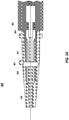
- FIGS 2A and 2B illustrate an example of a catheter assembly 200 that includes a blood control valve.
- Catheter assembly 200 includes a catheter hub 201 that employs an actuator 207 and a needle shield 203.
- Needle shield 203 contains a needle hub 204 which contains a needle 205.
- Actuator 207 is designed to be forced through septum 206 when another access device is connected to catheter hub 201 to thereby open a fluid pathway through catheter hub 201. Because of the presence of actuator 207 within catheter hub 201, there is little or no additional space within catheter hub 201 into which needle hub 203 could extend.
- actuator 207 is forced through septum 206 by access devices that are connected to catheter hub 201, actuator 207 must have a proximal end that the access devices can press against as the access devices are connected to catheter hub 201. Accordingly, the proximal end of actuator 207 is typically larger in size (e.g. as shown in Figures 2A and 2B ) which further minimizes the amount of space available at the proximal end of catheter hub 201.
- FIG. 2A catheter hub 201 and needle shield 203 are connected so that the components are coaxially aligned.
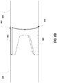
- Figure 2B illustrates the state of catheter assembly 200 while a clinician is handling the assembly to insert needle 205 into a patient's vasculature. As shown, the clinician typically grips assembly 200 and applies a downward and forward force to propel needle 205 through the patient's skin. This downward force causes catheter hub 201 and needle shield 203 to flex relative to each other as shown in Figure 2B .
- a substantial amount of flexing may occur because the pivot point between catheter hub 201 and needle shield 203 is formed where the two components connect. Because of this, the primary structure that resists flexing is the portion of needle shield 203 that extends into catheter hub 201. Because this portion is relatively short and thin, it cannot provide significant strength to withstand the flexing forces. As a result, an undesirable amount of flexing often occurs.
- the flexing between the catheter hub and the needle shield creates various problems. Primarily, when the components flex, the amount of force transferred to the needle is reduced thereby making it more difficult to insert the needle through the patient's skin. Also, when this flexing occurs, the clinician perceives the components as being weak which may cause the clinician to alter the catheter insertion procedure or to view the catheter assembly as being unsatisfactory. In some cases, this flexing may also lead to failure of the components.
- the present invention extends to a design of a needle hub and an actuator of a catheter assembly that allows the needle hub and actuator to interlock within the catheter hub.
- This interlocking allows the needle hub to be inserted into the catheter hub thereby increasing the rigidity of the catheter assembly.
- the interlocking can be accomplished by forming one or more channels in the proximal end of the actuator and one or more corresponding protrusions that extend from the distal end of the needle hub.
- the channels and protrusions can be formed at the top and bottom of the catheter hub and needle hub respectively to thereby increase the vertical rigidity of the catheter assembly. The increase in vertical rigidity can prevent flexing of the catheter hub with respect to the needle shield when a downward force is applied to the catheter assembly such as is common during insertion of the needle.
- the present invention is implemented as a catheter assembly comprising a catheter hub and a needle shield.
- the catheter hub contains an actuator and a septum.
- the actuator is configured to pierce the septum when a force is applied to the actuator.
- the needle shield is connected to the catheter hub and contains a needle hub.
- the needle hub contains a needle that extends through the catheter hub.
- the needle hub also includes one or more protrusions that extend from a distal end of the needle hub while the actuator includes one or more channels that extend from a proximal end and into the actuator. The one or more protrusions of the needle hub insert into the one or more channels thereby interlocking the needle hub with the actuator to provide greater rigidity between the catheter hub and the needle shield.
- the actuator includes two channels and the needle hub includes two protrusions. These channels can be positioned at the top and bottom of the actuator to provide greater rigidity against vertical forces applied to the catheter assembly.
- the actuator is positioned completely within the catheter hub such that the needle hub extends into the catheter hub to interlock with the actuator.
- the protrusions extend distally from the outer diameter of the needle hub.
- the outer diameter of the protrusions can also match the outer diameter of the channels.
- the protrusions extend into the catheter hub.
- the catheter assembly is an intravenous catheter assembly where the needle shield is detachable from the catheter hub to allow another access device to be connected to the catheter hub.
- the present invention extends to a design of a needle hub and an actuator of a catheter assembly that allows the needle hub and actuator to interlock within the catheter hub.
- This interlocking allows the needle hub to be inserted into the catheter hub thereby increasing the rigidity of the catheter assembly.
- the interlocking is accomplished by forming one or more channels in the proximal end of the actuator and one or more corresponding protrusions that extend from the distal end of the needle hub.
- the channels and protrusions can be formed at the top and bottom of the catheter hub and needle hub respectively to thereby increase the vertical rigidity of the catheter assembly. The increase in vertical rigidity can prevent flexing of the catheter hub with respect to the needle shield when a downward force is applied to the catheter assembly such as is common during insertion of the needle.
- the present invention is implemented as a catheter assembly comprising a catheter hub and a needle shield.
- the catheter hub contains an actuator and a septum.
- the actuator is configured to pierce the septum when a force is applied to the actuator.
- the needle shield is connected to the catheter hub and contains a needle hub.
- the needle hub contains a needle that extends through the catheter hub.
- the needle hub also includes one or more protrusions that extend from a distal end of the needle hub while the actuator includes one or more channels that extend from a proximal end and into the actuator. The one or more protrusions of the needle hub insert into the one or more channels thereby interlocking the needle hub with the actuator to provide greater rigidity between the catheter hub and the needle shield.
- the present invention comprises an actuator for use within a catheter hub.
- the actuator comprises a main body extending from a distal end to a proximal end.
- the distal end is configured to pierce a septum when a force is applied to the proximal end.
- the proximal end includes one or more channels that extend towards the distal end.
- the one or more channels are sized and shaped to receive one or more protrusions of a needle hub contained within a needle shield to thereby interlock the actuator and the needle hub to provide greater rigidity between the catheter hub and the needle shield.
- the present invention comprises a needle hub for use within a needle shield.
- the needle hub comprises a main body extending from a distal end to a proximal end.
- the main body contains a needle that extends out from the distal end.
- the distal end is configured with one or more protrusions that extend distally from the distal end.
- the one or more protrusions are configured to be inserted into corresponding channels formed in an actuator of a catheter hub.
- FIG. 3 illustrates a catheter assembly 300 in accordance with one or more embodiments of the invention.
- Catheter assembly 300 includes a catheter hub 301 that interconnects with a needle shield 303.
- Catheter hub 301 includes a septum 306 and an actuator 307 for piercing septum 306 with another access device is connected to catheter hub 301.
- Needle shield 303 includes a needle hub 304 that contains a needle 305. Once needle 305 has been used to insert a catheter into a patient's vasculature, needle hub 304 can be retracted further into needle shield 303 so that needle 305 is fully contained within needle shield 303. Needle shield 303 can then be disconnected from catheter hub 301 to allow other access devices to be connected to catheter hub 301.
- actuator 307 and needle hub 304 are configured to interlock. In this way, needle hub 304 can insert into actuator 307. This interlocking provides greater rigidity between catheter hub 301 and needle shield 303. Specifically, because needle hub 304 extends into actuator 307, the amount of flexing that can occur between catheter hub 301 and needle shield 303 is reduced. This reduced amount of flexing will cause more force to be transferred to needle 305 during the needle insertion process and will provide the clinician with a better feel.
- Figure 3C illustrates a perspective view of one example of how actuator 307 and needle hub 304 can interlock.
- actuator 307 can include an opening 307a at its proximal end that is sufficiently large to allow the distal end of needle hub 304 to insert into the opening.
- this configuration can provide an increased amount of rigidity between catheter hub 301 and needle shield 303.
- Figures 4 and 5 illustrate another configuration of an actuator 400 and needle hub 500 respectively which can be employed to increase the rigidity between the catheter hub and needle shield without sacrificing the structural integrity of the actuator.
- actuator 400 includes a proximal end 402 and a distal end 401.
- Proximal end 402 is configured to be contacted by an access device when the access device is attached to the catheter hub so that actuator 400 is forced through a septum by the access device.
- Proximal end 402 has a generally circular shape which provides the area against which the access device applies a force. However, to allow needle hub 500 to interlock with actuator 400 without sacrificing the structural integrity of actuator 400, two channels 403 are formed within proximal end 402. Channels 403 are formed at the top and bottom of actuator 400. The purpose of positioning channels 403 in this manner will be described below after needle hub 500 is described. Even with channels 403, a substantial amount of proximal end 402 remains to provide a contact area against which an access device can press to force actuator 400 through the septum and to provide structural integrity to actuator 400.
- needle hub 500 includes a proximal end 502 and a distal end 501.
- Distal end 501 includes protrusions 503.
- Protrusions 503 are positioned at the top and bottom of needle hub 500 and are shaped to conform to channels 403 formed in actuator 400. Accordingly, protrusions 503 can insert into channels 403 to interlock actuator 400 and needle hub 500.
- Channels 403 and protrusions 503 are positioned at the top and bottom of the respective components to provide reinforcement in the vertical direction. Because the flexing between the catheter hub and needle shield is primarily due to the downward force applied by the clinician during needle insertion, the positioning of channels 403 and protrusions 503 at the top and bottom provides support against the downward force thereby minimizing the amount of flexing that can occur between the catheter hub and needle shield. Although this design may not provide substantial increases in the rigidity of the components in the horizontal direction, such rigidity in the horizontal direction is generally not critical because it is oftentimes not desired to apply a horizontal force to the catheter assembly during needle insertion.
- Figures 6A and 6B provide a perspective view of actuator 400 and needle hub 500 in an unlocked and an interlocked configuration respectively.
- needle hub 500 is adjacent to, but not inserted into, actuator 400.
- protrusions 503 are configured to match the general shape of channels 403.
- needle hub 500 is shown as having been inserted into actuator 400 such that protrusions 503 are interlocked with channels 403.
- Figure 6C again illustrates actuator 400 and needle hub 500 in an unlocked configuration with the indications of the side views shown in Figures 6D and 6E .
- a right side view of actuator 400 is shown while in Figure 6E a left side view of needle hub 500 is shown.
- channels 403 are positioned at the top and bottom of actuator 400.
- protrusions 503 are shown at the top and bottom of needle hub 500 corresponding to the position of channels 403.
- actuator 400 and needle hub 500 are shown having two channels 403 and two protrusions 503 respectively, an actuator and needle hub can be configured with one or more channels and protrusions respectively.
- an actuator can have a single channel at the top while the corresponding needle hub has a single protrusion at the top. This configuration could still provide an increase in rigidity between the catheter hub and the needle shield, but in many cases will not be as effective as when two channels and protrusions are used.
- an actuator can include more than two channels (e.g. two channels positioned on the left and right side in additional to the channels 403 shown in Figure 6D ).
- the needle hub can include corresponding protrusions. This configuration would provide additional rigidity in the horizontal direction if such rigidity is desired.
- the structural integrity of the actuator can be compromised. Accordingly, even though more than two channels/protrusions can be used, in preferred embodiments, the actuator includes two channels as has been described.
- the portions of the distal end 402 of actuator 400 that extend between channels 403 are labeled as 650.
- Portions 650 form the surface area against which another access device applies a force to actuator 400 to force actuator 400 through the septum. As shown, even with channels 403, a substantial amount of surface area remains to provide adequate structural integrity to actuator 400 to receive such forces. Also, because channels 403 and protrusions 503 are used, the interlocking is accomplished while portions 650 remain positioned near the proximal end of the catheter hub. Having portions 650 near the proximal end of the catheter hub is important to ensure that actuator 400 will be forced through the septum when another access device is connected to the catheter hub.
- the size of channels 403 (and as a result, the size of protrusions 503) can be selected to maximize the rigidity between the catheter hub and needle shield without sacrificing the structural integrity of actuator 400.
- This size can vary depending on the type of material from which actuator 400 is made, the intended use of a catheter assembly employing actuator 400 such as the types of access devices that will be attached to the catheter hub, etc.
- the number of channels formed in actuator 400 can also be based on such considerations. For example, in some cases, it may be more desirable to provide greater rigidity to the catheter assembly in the horizontal direction than to maintain a certain level of structural integrity within the actuator. For example, in some cases, it may be necessary to apply downward and sideward forces to the catheter adapter during needle insertion. In such cases, an actuator having channels on the sides can be used to increase rigidity in the horizontal direction as well.
- Figures 7A and 7B depict a cross-sectional view of a catheter assembly 700 that is similar to catheter assembly 200 of Figures 2A and 2B .
- catheter assembly 700 includes actuator 400 and needle hub 500.
- actuator 400 includes channels 403 (represented by lines running upwards to the right) while needle hub 500 includes protrusions (represented by lines running downwards to the right).
- the area where channels 403 and protrusions 503 interlock is represented by the cross-hatching.
- catheter assembly 700 In contrast to catheter assembly 200 shown in Figure 2A , in catheter assembly 700, the positions of actuator 400 and needle hub 500 within catheter hub 701 substantially overlap. This overlapping increases the rigidity of catheter assembly 700.
- the increase in the rigidity of catheter assembly 700 is primarily due to the spreading of the pivot point between catheter hub 701 and needle shield 702.
- the pivot point is spread along the length of the interface between actuator 500 and needle hub 600.
- the interlocked area created by channels 403 and protrusions 503 forms the pivot point for any flexing between catheter hub 700 and needle shield 701. Because this pivot point is substantially longer than the pivot point shown in Figure 2B , a much greater force is required to cause flexing between catheter hub 700 and needle shield 701.
- the interlocked area is created using channels 403 and protrusions 503 (i.e. by using a portion of the end of each component rather than overlapping the entire ends as shown in Figure 3C ), the increased rigidity can be provided without sacrificing the structural integrity of actuator 400.
- Figure 8 provides a photograph of an actual implementation of a catheter assembly in accordance with one or more embodiments of the invention.
- the tip of the interlocking actuator is identified and would be similar to distal end 402 of actuator 400.
- a protrusion is identified as extending past the identified tip of the interlocking actuator and into a channel of the interlocking actuator.
- a similar protrusion extends into a corresponding channel on the bottom of the depicted catheter assembly. Because the interlocking needle hub extends substantially into the catheter hub, and because the needle hub interlocks with the actuator, a greater amount of rigidity is provided between the needle shield and catheter hub.
Landscapes
- Health & Medical Sciences (AREA)
- Life Sciences & Earth Sciences (AREA)
- Biophysics (AREA)
- Pulmonology (AREA)
- Engineering & Computer Science (AREA)
- Anesthesiology (AREA)
- Biomedical Technology (AREA)
- Heart & Thoracic Surgery (AREA)
- Hematology (AREA)
- Animal Behavior & Ethology (AREA)
- General Health & Medical Sciences (AREA)
- Public Health (AREA)
- Veterinary Medicine (AREA)
- Infusion, Injection, And Reservoir Apparatuses (AREA)
- Media Introduction/Drainage Providing Device (AREA)
- Materials For Medical Uses (AREA)
Description
- The present invention relates generally to intravenous (IV) catheter assemblies and particularly to increasing the rigidity between a catheter hub and a needle shield of the assembly to facilitate the threading of the catheter.
-
Figure 1 illustrates a common IVcatheter assembly 100 that consists of acatheter hub 101 and aneedle shield 103.Needle shield 103 contains a needle hub from which aneedle 102 extends.Needle 102 extends throughcatheter hub 101 and is used to thread the catheter into the vasculature of a patient. IVcatheter assembly 100 is initially handled by a clinician as a single component. The clinician inserts needle 102 into the patient's vasculature and then slides the catheter over top of the needle further into the vasculature. Once the catheter is placed appropriately in the vasculature,needle 102 can be retracted intoneedle shield 103. Then,needle shield 103 can be detached fromcatheter hub 101 leavingcatheter hub 101 for connection of other devices for blood draw or fluid injection. - Because
needle shield 103 andcatheter hub 101 are separate components, a certain amount of flexibility may exist between the two components. If this amount of flexibility is too great, the clinician may experience difficulty when insertingneedle 102 into the patient's vasculature. - Typically,
catheter hub 101 is configured at a proximal end with a connector that is designed to receive a standard connector of another device. For example,catheter hub 101 is often configured to receive a male luer of another device. Because of this, there are limited options for reinforcing the connection betweencatheter hub 101 andneedle shield 103 to limit the amount of flexibility between the components whenneedle 102 is inserted. Any structural reinforcements must be made in such a way that other devices (e.g. male luers) will still be attachable tocatheter hub 101. - Also, many catheter hubs employ a blood control valve that includes components positioned inside of the catheter hub. For example, a catheter hub may include an actuator that is initially positioned near the proximal end of the catheter hub on one side of a septum, and is then forced distally through the septum to open a fluid path through the catheter hub. Because the actuator is positioned near the proximal end of the catheter hub, there is little area for providing structural reinforcements inside the catheter hub.
-
Figures 2A and2B illustrate an example of acatheter assembly 200 that includes a blood control valve.Catheter assembly 200 includes acatheter hub 201 that employs anactuator 207 and aneedle shield 203.Needle shield 203 contains aneedle hub 204 which contains aneedle 205. Actuator 207 is designed to be forced throughseptum 206 when another access device is connected tocatheter hub 201 to thereby open a fluid pathway throughcatheter hub 201. Because of the presence ofactuator 207 withincatheter hub 201, there is little or no additional space withincatheter hub 201 into whichneedle hub 203 could extend. - Also, because
actuator 207 is forced throughseptum 206 by access devices that are connected tocatheter hub 201,actuator 207 must have a proximal end that the access devices can press against as the access devices are connected tocatheter hub 201. Accordingly, the proximal end ofactuator 207 is typically larger in size (e.g. as shown inFigures 2A and2B ) which further minimizes the amount of space available at the proximal end ofcatheter hub 201. - As shown in
Figure 2A ,catheter hub 201 andneedle shield 203 are connected so that the components are coaxially aligned. In contrast,Figure 2B illustrates the state ofcatheter assembly 200 while a clinician is handling the assembly to insertneedle 205 into a patient's vasculature. As shown, the clinician typically gripsassembly 200 and applies a downward and forward force to propelneedle 205 through the patient's skin. This downward force causescatheter hub 201 andneedle shield 203 to flex relative to each other as shown inFigure 2B . - A substantial amount of flexing may occur because the pivot point between
catheter hub 201 andneedle shield 203 is formed where the two components connect. Because of this, the primary structure that resists flexing is the portion ofneedle shield 203 that extends intocatheter hub 201. Because this portion is relatively short and thin, it cannot provide significant strength to withstand the flexing forces. As a result, an undesirable amount of flexing often occurs. - The flexing between the catheter hub and the needle shield creates various problems. Primarily, when the components flex, the amount of force transferred to the needle is reduced thereby making it more difficult to insert the needle through the patient's skin. Also, when this flexing occurs, the clinician perceives the components as being weak which may cause the clinician to alter the catheter insertion procedure or to view the catheter assembly as being unsatisfactory. In some cases, this flexing may also lead to failure of the components.
- See as well
WO 2009/091514 A2 . - The present invention, as claimed in
claim 1, extends to a design of a needle hub and an actuator of a catheter assembly that allows the needle hub and actuator to interlock within the catheter hub. This interlocking allows the needle hub to be inserted into the catheter hub thereby increasing the rigidity of the catheter assembly. The interlocking can be accomplished by forming one or more channels in the proximal end of the actuator and one or more corresponding protrusions that extend from the distal end of the needle hub. In some embodiments, the channels and protrusions can be formed at the top and bottom of the catheter hub and needle hub respectively to thereby increase the vertical rigidity of the catheter assembly. The increase in vertical rigidity can prevent flexing of the catheter hub with respect to the needle shield when a downward force is applied to the catheter assembly such as is common during insertion of the needle. - In some embodiments, the present invention is implemented as a catheter assembly comprising a catheter hub and a needle shield. The catheter hub contains an actuator and a septum. The actuator is configured to pierce the septum when a force is applied to the actuator. The needle shield is connected to the catheter hub and contains a needle hub. The needle hub contains a needle that extends through the catheter hub. The needle hub also includes one or more protrusions that extend from a distal end of the needle hub while the actuator includes one or more channels that extend from a proximal end and into the actuator. The one or more protrusions of the needle hub insert into the one or more channels thereby interlocking the needle hub with the actuator to provide greater rigidity between the catheter hub and the needle shield.
- In some embodiments, the actuator includes two channels and the needle hub includes two protrusions. These channels can be positioned at the top and bottom of the actuator to provide greater rigidity against vertical forces applied to the catheter assembly.
- In some embodiments, the actuator is positioned completely within the catheter hub such that the needle hub extends into the catheter hub to interlock with the actuator.
- In some embodiments, the protrusions extend distally from the outer diameter of the needle hub. The outer diameter of the protrusions can also match the outer diameter of the channels. In some embodiments, the protrusions extend into the catheter hub.
- In some embodiments, the catheter assembly is an intravenous catheter assembly where the needle shield is detachable from the catheter hub to allow another access device to be connected to the catheter hub.
- This summary is provided to introduce a selection of concepts in a simplified form that are further described below in the detailed description.
- Additional features and advantages of the invention will be set forth in the description which follows, and in part will be obvious from the description, or may be learned by the practice of the invention. The features and advantages of the invention may be realized and obtained by means of the instruments and combinations particularly pointed out in the appended claims. These and other features of the present invention will become more fully apparent from the following description and appended claims, or may be learned by the practice of the invention as set forth hereinafter.
- In order to describe the manner in which the above-recited and other advantages and features of the invention can be obtained, a more particular description of the invention briefly described above will be rendered by reference to specific embodiments thereof which are illustrated in the appended drawings. Understanding that these drawings depict only typical embodiments of the invention and are not therefore to be considered to be limiting of its scope, the invention will be described and explained with additional specificity and detail through the use of the accompanying drawings in which:
-
Figure 1 illustrates a prior art intravenous catheter assembly within which an actuator and needle hub configured according to embodiments of the present invention can be used to increase the rigidity of the catheter assembly in one or more directions; -
Figure 2A illustrates a cross-sectional view of a prior art intravenous catheter assembly that includes an actuator for piercing a septum and a needle hub; -
Figure 2B illustrates a cross-sectional view of the prior art intravenous catheter assembly ofFigure 2A in which the flexing between the catheter hub and needle shield caused by a downward force is depicted; -
Figure 3A illustrates a cross-sectional view of a catheter assembly that includes an actuator and needle hub configured in accordance with one or more embodiments of the invention; -
Figure 3B illustrates a cross-sectional view of the catheter assembly ofFigure 2A in which a downward force is applied to the catheter assembly without causing flexing between the catheter hub and needle shield due to the interlocking actuator and needle hub; -
Figure 3C illustrates a perspective view of a portion of an actuator and needle hub to illustrate one particular way in which the actuator and needle hub can be interlocked to increase the rigidity of a catheter assembly; -
Figure 4 illustrates a perspective view of an example of an actuator that includes channels formed at the top and bottom of the proximal end of the actuator which provide an interface for interlocking with protrusions of a needle hub; -
Figure 5 illustrates a perspective view of an example of a needle hub that includes protrusions formed at the top and bottom of the distal end of the needle hub which provide an interface for interlocking with channels of an actuator; -
Figure 6A illustrates a perspective view of an actuator having channels and a needle hub having protrusions in which the actuator and needle hub are in an unlocked position; -
Figure 6B illustrates a perspective view of the actuator and needle hub ofFigure 6A in which the actuator and needle hub are in an interlocked position; -
Figure 6C illustrates the perspective view of the actuator and needle hub ofFigure 6A with indications of views provided inFigures 6D and 6E ; -
Figure 6D illustrates a right side view of the actuator ofFigure 6C ; -
Figure 6E illustrates a left side view of the needle hub ofFigure 6C ; -
Figure 7A illustrates a cross-sectional view of a catheter assembly that includes an actuator having two channels and needle hub having two protrusions in which the actuator and needle hub are interlocked; -
Figure 7B illustrates a cross-sectional view of the catheter assembly ofFigure 7A in which no flexing occurs between the catheter hub and needle shield while a downward force is applied to the catheter assembly; and -
Figure 8 illustrates a photo of an implementation of a catheter assembly that includes an actuator and needle hub configured in accordance with an embodiment of the invention. - The presently preferred embodiments of the present invention will be best understood by reference to the drawings, wherein like reference numbers indicate identical or functionally similar elements. It will be readily understood that the components of the present invention, as generally described and illustrated in the figures herein, could be arranged and designed in a wide variety of different configurations. Thus, the following more detailed description, as represented in the figures, is not intended to limit the scope of the invention as claimed, but is merely representative of presently preferred embodiments of the invention.
- The present invention extends to a design of a needle hub and an actuator of a catheter assembly that allows the needle hub and actuator to interlock within the catheter hub. This interlocking allows the needle hub to be inserted into the catheter hub thereby increasing the rigidity of the catheter assembly. The interlocking is accomplished by forming one or more channels in the proximal end of the actuator and one or more corresponding protrusions that extend from the distal end of the needle hub. In some embodiments, the channels and protrusions can be formed at the top and bottom of the catheter hub and needle hub respectively to thereby increase the vertical rigidity of the catheter assembly. The increase in vertical rigidity can prevent flexing of the catheter hub with respect to the needle shield when a downward force is applied to the catheter assembly such as is common during insertion of the needle.
- The present invention is implemented as a catheter assembly comprising a catheter hub and a needle shield. The catheter hub contains an actuator and a septum. The actuator is configured to pierce the septum when a force is applied to the actuator. The needle shield is connected to the catheter hub and contains a needle hub. The needle hub contains a needle that extends through the catheter hub. The needle hub also includes one or more protrusions that extend from a distal end of the needle hub while the actuator includes one or more channels that extend from a proximal end and into the actuator. The one or more protrusions of the needle hub insert into the one or more channels thereby interlocking the needle hub with the actuator to provide greater rigidity between the catheter hub and the needle shield.
- The present invention comprises an actuator for use within a catheter hub. The actuator comprises a main body extending from a distal end to a proximal end. The distal end is configured to pierce a septum when a force is applied to the proximal end. The proximal end includes one or more channels that extend towards the distal end. The one or more channels are sized and shaped to receive one or more protrusions of a needle hub contained within a needle shield to thereby interlock the actuator and the needle hub to provide greater rigidity between the catheter hub and the needle shield.
- The present invention comprises a needle hub for use within a needle shield. The needle hub comprises a main body extending from a distal end to a proximal end. The main body contains a needle that extends out from the distal end. The distal end is configured with one or more protrusions that extend distally from the distal end. The one or more protrusions are configured to be inserted into corresponding channels formed in an actuator of a catheter hub.
-
Figure 3 illustrates acatheter assembly 300 in accordance with one or more embodiments of the invention.Catheter assembly 300 includes acatheter hub 301 that interconnects with aneedle shield 303.Catheter hub 301 includes aseptum 306 and anactuator 307 for piercingseptum 306 with another access device is connected tocatheter hub 301.Needle shield 303 includes aneedle hub 304 that contains aneedle 305. Onceneedle 305 has been used to insert a catheter into a patient's vasculature,needle hub 304 can be retracted further intoneedle shield 303 so thatneedle 305 is fully contained withinneedle shield 303.Needle shield 303 can then be disconnected fromcatheter hub 301 to allow other access devices to be connected tocatheter hub 301. - As shown,
actuator 307 andneedle hub 304 are configured to interlock. In this way,needle hub 304 can insert intoactuator 307. This interlocking provides greater rigidity betweencatheter hub 301 andneedle shield 303. Specifically, becauseneedle hub 304 extends intoactuator 307, the amount of flexing that can occur betweencatheter hub 301 andneedle shield 303 is reduced. This reduced amount of flexing will cause more force to be transferred toneedle 305 during the needle insertion process and will provide the clinician with a better feel. -
Figure 3C illustrates a perspective view of one example of howactuator 307 andneedle hub 304 can interlock. As shown,actuator 307 can include anopening 307a at its proximal end that is sufficiently large to allow the distal end ofneedle hub 304 to insert into the opening. In some implementations, this configuration can provide an increased amount of rigidity betweencatheter hub 301 andneedle shield 303. - However, in some cases, this configuration creates additional difficulties. In many cases, in order to have an
opening 307a that is sufficiently large to allowneedle hub 304 to extend sufficiently intoactuator 307, the outer wall ofactuator 307 aroundopening 307a becomes too narrow to provide an adequate surface against which another access device can press to forceactuator 307 throughseptum 306. For example, the outer wall can be required to be so narrow that another access device does not contact the outer wall when the access device is connected tocatheter hub 301. Similarly, the outer wall can be so narrow that it lacks sufficient strength to withstand the force necessary to forceactuator 307 throughseptum 306. Accordingly, in many implementations, the design shown inFigure 3C will not be preferred. -
Figures 4 and5 illustrate another configuration of anactuator 400 andneedle hub 500 respectively which can be employed to increase the rigidity between the catheter hub and needle shield without sacrificing the structural integrity of the actuator. As shown inFigure 4 ,actuator 400 includes aproximal end 402 and adistal end 401.Proximal end 402 is configured to be contacted by an access device when the access device is attached to the catheter hub so thatactuator 400 is forced through a septum by the access device. -
Proximal end 402 has a generally circular shape which provides the area against which the access device applies a force. However, to allowneedle hub 500 to interlock withactuator 400 without sacrificing the structural integrity ofactuator 400, twochannels 403 are formed withinproximal end 402.Channels 403 are formed at the top and bottom ofactuator 400. The purpose ofpositioning channels 403 in this manner will be described below afterneedle hub 500 is described. Even withchannels 403, a substantial amount ofproximal end 402 remains to provide a contact area against which an access device can press to forceactuator 400 through the septum and to provide structural integrity toactuator 400. - As shown in
Figure 5 ,needle hub 500 includes aproximal end 502 and adistal end 501.Distal end 501 includesprotrusions 503.Protrusions 503 are positioned at the top and bottom ofneedle hub 500 and are shaped to conform tochannels 403 formed inactuator 400. Accordingly,protrusions 503 can insert intochannels 403 to interlockactuator 400 andneedle hub 500. -
Channels 403 andprotrusions 503 are positioned at the top and bottom of the respective components to provide reinforcement in the vertical direction. Because the flexing between the catheter hub and needle shield is primarily due to the downward force applied by the clinician during needle insertion, the positioning ofchannels 403 andprotrusions 503 at the top and bottom provides support against the downward force thereby minimizing the amount of flexing that can occur between the catheter hub and needle shield. Although this design may not provide substantial increases in the rigidity of the components in the horizontal direction, such rigidity in the horizontal direction is generally not critical because it is oftentimes not desired to apply a horizontal force to the catheter assembly during needle insertion. -
Figures 6A and6B provide a perspective view ofactuator 400 andneedle hub 500 in an unlocked and an interlocked configuration respectively. InFigure 6A ,needle hub 500 is adjacent to, but not inserted into,actuator 400. As shown,protrusions 503 are configured to match the general shape ofchannels 403. InFigure 6B ,needle hub 500 is shown as having been inserted intoactuator 400 such thatprotrusions 503 are interlocked withchannels 403. -
Figure 6C again illustratesactuator 400 andneedle hub 500 in an unlocked configuration with the indications of the side views shown inFigures 6D and 6E . InFigure 6D , a right side view ofactuator 400 is shown while inFigure 6E a left side view ofneedle hub 500 is shown. As shown inFigure 6D ,channels 403 are positioned at the top and bottom ofactuator 400. Similarly, inFigure 6E ,protrusions 503 are shown at the top and bottom ofneedle hub 500 corresponding to the position ofchannels 403. - Although
actuator 400 andneedle hub 500 are shown having twochannels 403 and twoprotrusions 503 respectively, an actuator and needle hub can be configured with one or more channels and protrusions respectively. For example, in some embodiments, an actuator can have a single channel at the top while the corresponding needle hub has a single protrusion at the top. This configuration could still provide an increase in rigidity between the catheter hub and the needle shield, but in many cases will not be as effective as when two channels and protrusions are used. - Similarly, in some embodiments, an actuator can include more than two channels (e.g. two channels positioned on the left and right side in additional to the
channels 403 shown inFigure 6D ). In such cases, the needle hub can include corresponding protrusions. This configuration would provide additional rigidity in the horizontal direction if such rigidity is desired. However, as stated above, if an excessive number of channels are formed within the actuator, the structural integrity of the actuator can be compromised. Accordingly, even though more than two channels/protrusions can be used, in preferred embodiments, the actuator includes two channels as has been described. - Referring again to
Figure 6D , the portions of thedistal end 402 ofactuator 400 that extend betweenchannels 403 are labeled as 650.Portions 650 form the surface area against which another access device applies a force to actuator 400 to forceactuator 400 through the septum. As shown, even withchannels 403, a substantial amount of surface area remains to provide adequate structural integrity toactuator 400 to receive such forces. Also, becausechannels 403 andprotrusions 503 are used, the interlocking is accomplished whileportions 650 remain positioned near the proximal end of the catheter hub. Havingportions 650 near the proximal end of the catheter hub is important to ensure thatactuator 400 will be forced through the septum when another access device is connected to the catheter hub. - The size of channels 403 (and as a result, the size of protrusions 503) can be selected to maximize the rigidity between the catheter hub and needle shield without sacrificing the structural integrity of
actuator 400. This size can vary depending on the type of material from which actuator 400 is made, the intended use of a catheterassembly employing actuator 400 such as the types of access devices that will be attached to the catheter hub, etc. - The number of channels formed in
actuator 400 can also be based on such considerations. For example, in some cases, it may be more desirable to provide greater rigidity to the catheter assembly in the horizontal direction than to maintain a certain level of structural integrity within the actuator. For example, in some cases, it may be necessary to apply downward and sideward forces to the catheter adapter during needle insertion. In such cases, an actuator having channels on the sides can be used to increase rigidity in the horizontal direction as well. -
Figures 7A and7B depict a cross-sectional view of acatheter assembly 700 that is similar tocatheter assembly 200 ofFigures 2A and2B . However,catheter assembly 700 includesactuator 400 andneedle hub 500. As shown,actuator 400 includes channels 403 (represented by lines running upwards to the right) whileneedle hub 500 includes protrusions (represented by lines running downwards to the right). The area wherechannels 403 andprotrusions 503 interlock is represented by the cross-hatching. - In contrast to
catheter assembly 200 shown inFigure 2A , incatheter assembly 700, the positions ofactuator 400 andneedle hub 500 withincatheter hub 701 substantially overlap. This overlapping increases the rigidity ofcatheter assembly 700. - The increase in the rigidity of
catheter assembly 700 is primarily due to the spreading of the pivot point betweencatheter hub 701 andneedle shield 702. For example, as shown inFigure 7B , the pivot point is spread along the length of the interface betweenactuator 500 and needle hub 600. In other words, the interlocked area created bychannels 403 andprotrusions 503 forms the pivot point for any flexing betweencatheter hub 700 andneedle shield 701. Because this pivot point is substantially longer than the pivot point shown inFigure 2B , a much greater force is required to cause flexing betweencatheter hub 700 andneedle shield 701. - Also, because the interlocked area is created using
channels 403 and protrusions 503 (i.e. by using a portion of the end of each component rather than overlapping the entire ends as shown inFigure 3C ), the increased rigidity can be provided without sacrificing the structural integrity ofactuator 400. -
Figure 8 provides a photograph of an actual implementation of a catheter assembly in accordance with one or more embodiments of the invention. The tip of the interlocking actuator is identified and would be similar todistal end 402 ofactuator 400. Also, a protrusion is identified as extending past the identified tip of the interlocking actuator and into a channel of the interlocking actuator. A similar protrusion extends into a corresponding channel on the bottom of the depicted catheter assembly. Because the interlocking needle hub extends substantially into the catheter hub, and because the needle hub interlocks with the actuator, a greater amount of rigidity is provided between the needle shield and catheter hub. - The present invention may be embodied in other specific forms without departing from its essential characteristics. The described embodiments are to be considered in all respects only as illustrative and not restrictive. The scope of the invention is, therefore, indicated by the appended claims rather than by the foregoing description.
Claims (9)
- A catheter assembly comprising:a catheter hub (301) containing an actuator (307) and a septum (306), the actuator (307) configured to pierce the septum (306) when a force is applied to the actuator (307); anda needle shield (303) connected to the catheter hub (301), the needle shield (303) containing a needle hub (304), the needle hub (304) containing a needle (305) that extends through the catheter hub (301)characterized in thatthe needle hub (304) includes one or more protrusions (503) that extend from a distal end (501) of the needle hub (304); andthe actuator (307) includes one or more channels (403) that extend from a proximal end (402) and into the actuator (307), wherein the one or more protrusions (503) of the needle hub (304) insert into the one or more channels (403) thereby interlocking the needle hub (304) with the actuator (307) to provide greater rigidity between the catheter hub (301) and the needle shield (303).
- The catheter assembly of claim 1, wherein the actuator (307) includes two channels (403) and the needle hub (304) includes two protrusions (503).
- The catheter assembly of claim 2, wherein the channels (403) are positioned on opposite sides of the actuator (307) to provide greater rigidity against vertical forces applied to the catheter assembly.
- The catheter assembly of claim 1, wherein the needle hub (304) extends into the catheter hub (301) to interlock with the actuator (307).
- The catheter assembly of claim 1, wherein the protrusions (503) extend distally from the outer diameter of the needle hub (304).
- The catheter assembly of claim 1, wherein the outer diameter of the protrusions (503) matches the outer diameter of the channels (403).
- The catheter assembly of claim 1, wherein the protrusions (503) extend into the catheter hub (301).
- The catheter assembly of claim 1, wherein the catheter assembly is an intravenous catheter assembly.
- The catheter assembly of claim 1, wherein the needle shield (303) is detachable from the catheter hub (301) to allow another access device to be connected to the catheter hub (301).
Priority Applications (1)
| Application Number | Priority Date | Filing Date | Title |
|---|---|---|---|
| EP18208095.2A EP3470106B1 (en) | 2013-07-30 | 2014-07-17 | Interlocking needle hub and catheter hub actuator to increase rigidity of iv catheter assembly |
Applications Claiming Priority (2)
| Application Number | Priority Date | Filing Date | Title |
|---|---|---|---|
| US13/954,511 US9775972B2 (en) | 2013-07-30 | 2013-07-30 | Interlocking needle hub and catheter hub actuator to increase rigidity of IV catheter assembly |
| PCT/US2014/047047 WO2015017135A1 (en) | 2013-07-30 | 2014-07-17 | Interlocking needle hub and catheter hub actuator to increase rigidity of iv catheter assembly |
Related Child Applications (1)
| Application Number | Title | Priority Date | Filing Date |
|---|---|---|---|
| EP18208095.2A Division EP3470106B1 (en) | 2013-07-30 | 2014-07-17 | Interlocking needle hub and catheter hub actuator to increase rigidity of iv catheter assembly |
Publications (2)
| Publication Number | Publication Date |
|---|---|
| EP3027260A1 EP3027260A1 (en) | 2016-06-08 |
| EP3027260B1 true EP3027260B1 (en) | 2018-12-19 |
Family
ID=51266446
Family Applications (2)
| Application Number | Title | Priority Date | Filing Date |
|---|---|---|---|
| EP14747780.6A Active EP3027260B1 (en) | 2013-07-30 | 2014-07-17 | Interlocking needle hub and catheter hub actuator to increase rigidity of iv catheter assembly |
| EP18208095.2A Active EP3470106B1 (en) | 2013-07-30 | 2014-07-17 | Interlocking needle hub and catheter hub actuator to increase rigidity of iv catheter assembly |
Family Applications After (1)
| Application Number | Title | Priority Date | Filing Date |
|---|---|---|---|
| EP18208095.2A Active EP3470106B1 (en) | 2013-07-30 | 2014-07-17 | Interlocking needle hub and catheter hub actuator to increase rigidity of iv catheter assembly |
Country Status (11)
| Country | Link |
|---|---|
| US (1) | US9775972B2 (en) |
| EP (2) | EP3027260B1 (en) |
| JP (1) | JP6441924B2 (en) |
| CN (1) | CN105530983B (en) |
| AU (1) | AU2014296640B2 (en) |
| BR (1) | BR112016002266B1 (en) |
| CA (1) | CA2919785C (en) |
| ES (1) | ES2716090T3 (en) |
| MX (1) | MX367285B (en) |
| SG (1) | SG11201600653XA (en) |
| WO (1) | WO2015017135A1 (en) |
Families Citing this family (44)
| Publication number | Priority date | Publication date | Assignee | Title |
|---|---|---|---|---|
| DE602006005674D1 (en) | 2005-07-06 | 2009-04-23 | Vascular Pathways Inc | DEVICE FOR INTRAVENOUS CATHETER INTRODUCTION AND USE METHOD |
| JP5139518B2 (en) | 2007-05-07 | 2013-02-06 | バスキュラー・パスウェイズ・インコーポレイテッド | Venous catheter insertion device |
| US9872971B2 (en) | 2010-05-14 | 2018-01-23 | C. R. Bard, Inc. | Guidewire extension system for a catheter placement device |
| US8932258B2 (en) | 2010-05-14 | 2015-01-13 | C. R. Bard, Inc. | Catheter placement device and method |
| US10384039B2 (en) | 2010-05-14 | 2019-08-20 | C. R. Bard, Inc. | Catheter insertion device including top-mounted advancement components |
| US11925779B2 (en) | 2010-05-14 | 2024-03-12 | C. R. Bard, Inc. | Catheter insertion device including top-mounted advancement components |
| US9950139B2 (en) | 2010-05-14 | 2018-04-24 | C. R. Bard, Inc. | Catheter placement device including guidewire and catheter control elements |
| US8690833B2 (en) | 2011-01-31 | 2014-04-08 | Vascular Pathways, Inc. | Intravenous catheter and insertion device with reduced blood spatter |
| EP3563898B1 (en) | 2011-02-25 | 2020-11-11 | C.R. Bard, Inc. | Medical component insertion device including a retractable needle |
| US9186100B2 (en) | 2011-04-26 | 2015-11-17 | Velano Vascular, Inc. | Systems and methods for phlebotomy through a peripheral IV catheter |
| US8366685B2 (en) | 2011-04-26 | 2013-02-05 | Creative Vascular, Llc | Systems and methods for phlebotomy through a peripheral IV catheter |
| US10076272B2 (en) | 2011-04-26 | 2018-09-18 | Velano Vascular, Inc. | Systems and methods for phlebotomy through a peripheral IV catheter |
| USD903101S1 (en) | 2011-05-13 | 2020-11-24 | C. R. Bard, Inc. | Catheter |
| CN105102054B (en) | 2013-01-30 | 2018-04-20 | 血管通路股份有限公司 | Systems and methods for venipuncture and catheter placement |
| WO2016037127A1 (en) | 2014-09-05 | 2016-03-10 | C.R. Bard, Inc. | Catheter insertion device including retractable needle |
| KR20170077162A (en) | 2014-10-28 | 2017-07-05 | 쓰리엠 이노베이티브 프로퍼티즈 컴파니 | Spray application system components comprising a repellent surface and methods |
| USD903100S1 (en) | 2015-05-01 | 2020-11-24 | C. R. Bard, Inc. | Catheter placement device |
| WO2016187037A1 (en) | 2015-05-15 | 2016-11-24 | C.R.Bard, Inc. | Catheter placement device including an extensible needle safety component |
| EP3552652B2 (en) | 2015-08-18 | 2024-07-03 | B. Braun Melsungen AG | Catheter devices with valves |
| CN108350290B (en) | 2015-10-28 | 2021-10-15 | 3M创新有限公司 | Articles subject to ice formation including repellent surfaces |
| US10300247B2 (en) | 2016-02-03 | 2019-05-28 | Velano Vascular, Inc. | Devices and methods for fluid transfer through a placed peripheral intravenous catheter |
| US10898223B2 (en) | 2016-03-28 | 2021-01-26 | Becton, Dickinson And Company | Multi-diameter cannula |
| EP3448944A4 (en) | 2016-04-26 | 2019-11-13 | 3M Innovative Properties Company | ARTICLES SUBJECTED TO ICE FORMATION COMPRISING A REPELLENT SURFACE COMPRISING A SILOXANE MATERIAL |
| CN109715093B (en) * | 2016-09-12 | 2020-11-06 | C·R·巴德股份有限公司 | Blood Control for Catheterization Devices |
| US11400260B2 (en) | 2017-03-01 | 2022-08-02 | C. R. Bard, Inc. | Catheter insertion device |
| CN114470485B (en) | 2017-03-21 | 2024-09-13 | 威蓝诺血管股份有限公司 | Apparatus and method for fluid delivery through a placed peripheral intravenous catheter |
| US10773056B2 (en) | 2017-03-21 | 2020-09-15 | Velano Vascular, Inc. | Systems and methods for controlling catheter device size |
| JP7237858B2 (en) | 2017-05-26 | 2023-03-13 | パイパー・アクセス、エルエルシー | Catheter delivery device, system and method |
| WO2019065943A1 (en) | 2017-09-29 | 2019-04-04 | テルモ株式会社 | Catheter assembly and medical valve |
| CN115671504A (en) | 2018-03-07 | 2023-02-03 | 巴德阿克塞斯系统股份有限公司 | Guidewire advancement and blood flashback system for medical device insertion systems |
| USD921884S1 (en) | 2018-07-27 | 2021-06-08 | Bard Access Systems, Inc. | Catheter insertion device |
| WO2020127328A1 (en) | 2018-12-17 | 2020-06-25 | B. Braun Melsungen Ag | Over-the-needle catheter assemblies and related manufacturing method |
| JP7387717B2 (en) | 2019-03-28 | 2023-11-28 | テルモ株式会社 | catheter assembly |
| CN213312819U (en) | 2019-08-19 | 2021-06-01 | 贝克顿·迪金森公司 | Midline catheter placement device |
| WO2021035026A1 (en) | 2019-08-20 | 2021-02-25 | Velano Vascular, Inc. | Fluid transfer devices with extended length catheters and methods of using the same |
| WO2021048867A1 (en) | 2019-09-10 | 2021-03-18 | Neeraj Gupta | An intravenous catheter device |
| WO2021054980A1 (en) | 2019-09-20 | 2021-03-25 | Bard Peripheral Vascular, Inc. | Intravenous catheter-placement device |
| USD975844S1 (en) * | 2019-11-06 | 2023-01-17 | Free Life Medical Gmbh | Cannula |
| US12329918B2 (en) * | 2020-06-09 | 2025-06-17 | Becton, Dickinson And Company | Needle cover retention |
| BR112023004592A2 (en) * | 2020-09-15 | 2023-04-11 | Becton Dickinson Co | ANGLE CHANGING CATHETERS SET AND RELATED METHODS |
| CA3197752A1 (en) | 2020-11-26 | 2022-06-02 | Avia Vascular, Llc | Blood collection devices, systems, and methods |
| WO2022172281A1 (en) | 2021-02-10 | 2022-08-18 | Neeraj Gupta | Intravenous cannula |
| US12337123B2 (en) | 2021-05-06 | 2025-06-24 | Medsource Labs, Llc | Safety intravenous cannula |
| US12186497B2 (en) | 2022-01-14 | 2025-01-07 | Medsource International Llc | Intravenous cannula |
Family Cites Families (13)
| Publication number | Priority date | Publication date | Assignee | Title |
|---|---|---|---|---|
| GB8627808D0 (en) | 1986-11-20 | 1986-12-17 | Cox J A | Sampling liquids from human/animal body |
| US5156596A (en) * | 1991-02-04 | 1992-10-20 | Menlo Care, Inc. | Catheter with changeable number of lumens |
| US5391152A (en) * | 1993-03-12 | 1995-02-21 | C. R. Bard, Inc. | Catheter interlock assembly |
| US5772643A (en) * | 1996-02-29 | 1998-06-30 | Becton Dickinson And Company | Barbed luer adapter |
| US6213978B1 (en) * | 1998-10-27 | 2001-04-10 | Cherie A. Voyten | Intravenous catheter insertion apparatus |
| JP4996015B2 (en) * | 2001-03-12 | 2012-08-08 | メディキット株式会社 | Indwelling catheter |
| US6872193B2 (en) * | 2001-10-26 | 2005-03-29 | Retractable Technologies, Inc. | IV catheter introducer with retractable needle |
| US8048031B2 (en) * | 2001-10-26 | 2011-11-01 | Retractable Technologies, Inc. | IV catheter introducer |
| ES2697329T3 (en) * | 2002-06-20 | 2019-01-23 | Becton Dickinson Co | Apparatus to protect the tip of a catheter introducer needle |
| US8343104B2 (en) * | 2007-06-29 | 2013-01-01 | Medical Components, Inc. | Closable and openable catheter assembly and method of using same |
| CA2901300A1 (en) | 2008-01-14 | 2009-07-23 | I-V Access Technology, Inc. | An apparatus for peripheral vascular access |
| US8361038B2 (en) | 2009-02-11 | 2013-01-29 | Becton, Dickinson And Company | Systems and methods for providing a flow control valve for a medical device |
| DE202009009602U1 (en) | 2009-07-15 | 2009-12-10 | B. Braun Melsungen Ag | Catheter device with needle guard |
-
2013
- 2013-07-30 US US13/954,511 patent/US9775972B2/en active Active
-
2014
- 2014-07-17 SG SG11201600653XA patent/SG11201600653XA/en unknown
- 2014-07-17 WO PCT/US2014/047047 patent/WO2015017135A1/en not_active Ceased
- 2014-07-17 CN CN201480050046.2A patent/CN105530983B/en active Active
- 2014-07-17 BR BR112016002266-1A patent/BR112016002266B1/en active IP Right Grant
- 2014-07-17 JP JP2016531737A patent/JP6441924B2/en active Active
- 2014-07-17 EP EP14747780.6A patent/EP3027260B1/en active Active
- 2014-07-17 EP EP18208095.2A patent/EP3470106B1/en active Active
- 2014-07-17 MX MX2016001367A patent/MX367285B/en active IP Right Grant
- 2014-07-17 CA CA2919785A patent/CA2919785C/en active Active
- 2014-07-17 AU AU2014296640A patent/AU2014296640B2/en active Active
- 2014-07-17 ES ES14747780T patent/ES2716090T3/en active Active
Non-Patent Citations (1)
| Title |
|---|
| None * |
Also Published As
| Publication number | Publication date |
|---|---|
| CN105530983A (en) | 2016-04-27 |
| EP3027260A1 (en) | 2016-06-08 |
| CN105530983B (en) | 2019-08-06 |
| SG11201600653XA (en) | 2016-02-26 |
| WO2015017135A1 (en) | 2015-02-05 |
| MX2016001367A (en) | 2016-05-05 |
| EP3470106A1 (en) | 2019-04-17 |
| US20150038909A1 (en) | 2015-02-05 |
| EP3470106C0 (en) | 2025-08-27 |
| BR112016002266A2 (en) | 2017-08-01 |
| MX367285B (en) | 2019-08-13 |
| US9775972B2 (en) | 2017-10-03 |
| AU2014296640A1 (en) | 2016-02-25 |
| BR112016002266B1 (en) | 2021-10-13 |
| JP6441924B2 (en) | 2018-12-19 |
| JP2016527027A (en) | 2016-09-08 |
| EP3470106B1 (en) | 2025-08-27 |
| CA2919785A1 (en) | 2015-02-05 |
| ES2716090T3 (en) | 2019-06-10 |
| AU2014296640B2 (en) | 2018-07-19 |
| CA2919785C (en) | 2021-03-02 |
Similar Documents
| Publication | Publication Date | Title |
|---|---|---|
| CA2919785C (en) | Interlocking needle hub and catheter hub actuator to increase rigidity of iv catheter assembly | |
| US12005199B2 (en) | Catheter adapter port valve | |
| EP3695872B1 (en) | Compliant catheter adapter having self-slitting needle | |
| US10478609B2 (en) | Blood control catheter valve employing actuator with flexible retention arms | |
| EP3368126B1 (en) | Compliant catheter adapter and compression cap | |
| KR20210055696A (en) | Peripheral intravenous catheter assembly with tool set | |
| US12589224B2 (en) | Low profile access sheaths | |
| KR20210057728A (en) | Catheter stabilization platform, system and method | |
| HK40044006A (en) | Catheter assemblies and related methods |
Legal Events
| Date | Code | Title | Description |
|---|---|---|---|
| PUAI | Public reference made under article 153(3) epc to a published international application that has entered the european phase |
Free format text: ORIGINAL CODE: 0009012 |
|
| 17P | Request for examination filed |
Effective date: 20160216 |
|
| AK | Designated contracting states |
Kind code of ref document: A1 Designated state(s): AL AT BE BG CH CY CZ DE DK EE ES FI FR GB GR HR HU IE IS IT LI LT LU LV MC MK MT NL NO PL PT RO RS SE SI SK SM TR |
|
| AX | Request for extension of the european patent |
Extension state: BA ME |
|
| DAX | Request for extension of the european patent (deleted) | ||
| RAP1 | Party data changed (applicant data changed or rights of an application transferred) |
Owner name: BECTON, DICKINSON AND COMPANY |
|
| GRAP | Despatch of communication of intention to grant a patent |
Free format text: ORIGINAL CODE: EPIDOSNIGR1 |
|
| STAA | Information on the status of an ep patent application or granted ep patent |
Free format text: STATUS: GRANT OF PATENT IS INTENDED |
|
| INTG | Intention to grant announced |
Effective date: 20180704 |
|
| GRAS | Grant fee paid |
Free format text: ORIGINAL CODE: EPIDOSNIGR3 |
|
| GRAA | (expected) grant |
Free format text: ORIGINAL CODE: 0009210 |
|
| STAA | Information on the status of an ep patent application or granted ep patent |
Free format text: STATUS: THE PATENT HAS BEEN GRANTED |
|
| AK | Designated contracting states |
Kind code of ref document: B1 Designated state(s): AL AT BE BG CH CY CZ DE DK EE ES FI FR GB GR HR HU IE IS IT LI LT LU LV MC MK MT NL NO PL PT RO RS SE SI SK SM TR |
|
| REG | Reference to a national code |
Ref country code: GB Ref legal event code: FG4D |
|
| REG | Reference to a national code |
Ref country code: CH Ref legal event code: EP |
|
| REG | Reference to a national code |
Ref country code: IE Ref legal event code: FG4D |
|
| REG | Reference to a national code |
Ref country code: DE Ref legal event code: R096 Ref document number: 602014038221 Country of ref document: DE |
|
| REG | Reference to a national code |
Ref country code: AT Ref legal event code: REF Ref document number: 1078012 Country of ref document: AT Kind code of ref document: T Effective date: 20190115 |
|
| REG | Reference to a national code |
Ref country code: NL Ref legal event code: MP Effective date: 20181219 |
|
| PG25 | Lapsed in a contracting state [announced via postgrant information from national office to epo] |
Ref country code: NO Free format text: LAPSE BECAUSE OF FAILURE TO SUBMIT A TRANSLATION OF THE DESCRIPTION OR TO PAY THE FEE WITHIN THE PRESCRIBED TIME-LIMIT Effective date: 20190319 Ref country code: BG Free format text: LAPSE BECAUSE OF FAILURE TO SUBMIT A TRANSLATION OF THE DESCRIPTION OR TO PAY THE FEE WITHIN THE PRESCRIBED TIME-LIMIT Effective date: 20190319 Ref country code: FI Free format text: LAPSE BECAUSE OF FAILURE TO SUBMIT A TRANSLATION OF THE DESCRIPTION OR TO PAY THE FEE WITHIN THE PRESCRIBED TIME-LIMIT Effective date: 20181219 Ref country code: LT Free format text: LAPSE BECAUSE OF FAILURE TO SUBMIT A TRANSLATION OF THE DESCRIPTION OR TO PAY THE FEE WITHIN THE PRESCRIBED TIME-LIMIT Effective date: 20181219 Ref country code: LV Free format text: LAPSE BECAUSE OF FAILURE TO SUBMIT A TRANSLATION OF THE DESCRIPTION OR TO PAY THE FEE WITHIN THE PRESCRIBED TIME-LIMIT Effective date: 20181219 Ref country code: HR Free format text: LAPSE BECAUSE OF FAILURE TO SUBMIT A TRANSLATION OF THE DESCRIPTION OR TO PAY THE FEE WITHIN THE PRESCRIBED TIME-LIMIT Effective date: 20181219 |
|
| REG | Reference to a national code |
Ref country code: LT Ref legal event code: MG4D |
|
| REG | Reference to a national code |
Ref country code: AT Ref legal event code: MK05 Ref document number: 1078012 Country of ref document: AT Kind code of ref document: T Effective date: 20181219 |
|
| PG25 | Lapsed in a contracting state [announced via postgrant information from national office to epo] |
Ref country code: SE Free format text: LAPSE BECAUSE OF FAILURE TO SUBMIT A TRANSLATION OF THE DESCRIPTION OR TO PAY THE FEE WITHIN THE PRESCRIBED TIME-LIMIT Effective date: 20181219 Ref country code: AL Free format text: LAPSE BECAUSE OF FAILURE TO SUBMIT A TRANSLATION OF THE DESCRIPTION OR TO PAY THE FEE WITHIN THE PRESCRIBED TIME-LIMIT Effective date: 20181219 Ref country code: RS Free format text: LAPSE BECAUSE OF FAILURE TO SUBMIT A TRANSLATION OF THE DESCRIPTION OR TO PAY THE FEE WITHIN THE PRESCRIBED TIME-LIMIT Effective date: 20181219 Ref country code: GR Free format text: LAPSE BECAUSE OF FAILURE TO SUBMIT A TRANSLATION OF THE DESCRIPTION OR TO PAY THE FEE WITHIN THE PRESCRIBED TIME-LIMIT Effective date: 20190320 |
|
| REG | Reference to a national code |
Ref country code: ES Ref legal event code: FG2A Ref document number: 2716090 Country of ref document: ES Kind code of ref document: T3 Effective date: 20190610 |
|
| PG25 | Lapsed in a contracting state [announced via postgrant information from national office to epo] |
Ref country code: NL Free format text: LAPSE BECAUSE OF FAILURE TO SUBMIT A TRANSLATION OF THE DESCRIPTION OR TO PAY THE FEE WITHIN THE PRESCRIBED TIME-LIMIT Effective date: 20181219 |
|
| PG25 | Lapsed in a contracting state [announced via postgrant information from national office to epo] |
Ref country code: PT Free format text: LAPSE BECAUSE OF FAILURE TO SUBMIT A TRANSLATION OF THE DESCRIPTION OR TO PAY THE FEE WITHIN THE PRESCRIBED TIME-LIMIT Effective date: 20190419 Ref country code: CZ Free format text: LAPSE BECAUSE OF FAILURE TO SUBMIT A TRANSLATION OF THE DESCRIPTION OR TO PAY THE FEE WITHIN THE PRESCRIBED TIME-LIMIT Effective date: 20181219 Ref country code: PL Free format text: LAPSE BECAUSE OF FAILURE TO SUBMIT A TRANSLATION OF THE DESCRIPTION OR TO PAY THE FEE WITHIN THE PRESCRIBED TIME-LIMIT Effective date: 20181219 |
|
| PG25 | Lapsed in a contracting state [announced via postgrant information from national office to epo] |
Ref country code: SK Free format text: LAPSE BECAUSE OF FAILURE TO SUBMIT A TRANSLATION OF THE DESCRIPTION OR TO PAY THE FEE WITHIN THE PRESCRIBED TIME-LIMIT Effective date: 20181219 Ref country code: IS Free format text: LAPSE BECAUSE OF FAILURE TO SUBMIT A TRANSLATION OF THE DESCRIPTION OR TO PAY THE FEE WITHIN THE PRESCRIBED TIME-LIMIT Effective date: 20190419 Ref country code: SM Free format text: LAPSE BECAUSE OF FAILURE TO SUBMIT A TRANSLATION OF THE DESCRIPTION OR TO PAY THE FEE WITHIN THE PRESCRIBED TIME-LIMIT Effective date: 20181219 Ref country code: RO Free format text: LAPSE BECAUSE OF FAILURE TO SUBMIT A TRANSLATION OF THE DESCRIPTION OR TO PAY THE FEE WITHIN THE PRESCRIBED TIME-LIMIT Effective date: 20181219 Ref country code: EE Free format text: LAPSE BECAUSE OF FAILURE TO SUBMIT A TRANSLATION OF THE DESCRIPTION OR TO PAY THE FEE WITHIN THE PRESCRIBED TIME-LIMIT Effective date: 20181219 |
|
| REG | Reference to a national code |
Ref country code: DE Ref legal event code: R097 Ref document number: 602014038221 Country of ref document: DE |
|
| PLBE | No opposition filed within time limit |
Free format text: ORIGINAL CODE: 0009261 |
|
| STAA | Information on the status of an ep patent application or granted ep patent |
Free format text: STATUS: NO OPPOSITION FILED WITHIN TIME LIMIT |
|
| PG25 | Lapsed in a contracting state [announced via postgrant information from national office to epo] |
Ref country code: AT Free format text: LAPSE BECAUSE OF FAILURE TO SUBMIT A TRANSLATION OF THE DESCRIPTION OR TO PAY THE FEE WITHIN THE PRESCRIBED TIME-LIMIT Effective date: 20181219 Ref country code: DK Free format text: LAPSE BECAUSE OF FAILURE TO SUBMIT A TRANSLATION OF THE DESCRIPTION OR TO PAY THE FEE WITHIN THE PRESCRIBED TIME-LIMIT Effective date: 20181219 |
|
| 26N | No opposition filed |
Effective date: 20190920 |
|
| PG25 | Lapsed in a contracting state [announced via postgrant information from national office to epo] |
Ref country code: MC Free format text: LAPSE BECAUSE OF FAILURE TO SUBMIT A TRANSLATION OF THE DESCRIPTION OR TO PAY THE FEE WITHIN THE PRESCRIBED TIME-LIMIT Effective date: 20181219 Ref country code: SI Free format text: LAPSE BECAUSE OF FAILURE TO SUBMIT A TRANSLATION OF THE DESCRIPTION OR TO PAY THE FEE WITHIN THE PRESCRIBED TIME-LIMIT Effective date: 20181219 |
|
| REG | Reference to a national code |
Ref country code: CH Ref legal event code: PL |
|
| PG25 | Lapsed in a contracting state [announced via postgrant information from national office to epo] |
Ref country code: TR Free format text: LAPSE BECAUSE OF FAILURE TO SUBMIT A TRANSLATION OF THE DESCRIPTION OR TO PAY THE FEE WITHIN THE PRESCRIBED TIME-LIMIT Effective date: 20181219 |
|
| PG25 | Lapsed in a contracting state [announced via postgrant information from national office to epo] |
Ref country code: LU Free format text: LAPSE BECAUSE OF NON-PAYMENT OF DUE FEES Effective date: 20190717 Ref country code: LI Free format text: LAPSE BECAUSE OF NON-PAYMENT OF DUE FEES Effective date: 20190731 Ref country code: CH Free format text: LAPSE BECAUSE OF NON-PAYMENT OF DUE FEES Effective date: 20190731 |
|
| PG25 | Lapsed in a contracting state [announced via postgrant information from national office to epo] |
Ref country code: IE Free format text: LAPSE BECAUSE OF NON-PAYMENT OF DUE FEES Effective date: 20190717 |
|
| PG25 | Lapsed in a contracting state [announced via postgrant information from national office to epo] |
Ref country code: CY Free format text: LAPSE BECAUSE OF FAILURE TO SUBMIT A TRANSLATION OF THE DESCRIPTION OR TO PAY THE FEE WITHIN THE PRESCRIBED TIME-LIMIT Effective date: 20181219 |
|
| PG25 | Lapsed in a contracting state [announced via postgrant information from national office to epo] |
Ref country code: MT Free format text: LAPSE BECAUSE OF FAILURE TO SUBMIT A TRANSLATION OF THE DESCRIPTION OR TO PAY THE FEE WITHIN THE PRESCRIBED TIME-LIMIT Effective date: 20181219 Ref country code: HU Free format text: LAPSE BECAUSE OF FAILURE TO SUBMIT A TRANSLATION OF THE DESCRIPTION OR TO PAY THE FEE WITHIN THE PRESCRIBED TIME-LIMIT; INVALID AB INITIO Effective date: 20140717 |
|
| PG25 | Lapsed in a contracting state [announced via postgrant information from national office to epo] |
Ref country code: MK Free format text: LAPSE BECAUSE OF FAILURE TO SUBMIT A TRANSLATION OF THE DESCRIPTION OR TO PAY THE FEE WITHIN THE PRESCRIBED TIME-LIMIT Effective date: 20181219 |
|
| PGFP | Annual fee paid to national office [announced via postgrant information from national office to epo] |
Ref country code: GB Payment date: 20250619 Year of fee payment: 12 |
|
| PGFP | Annual fee paid to national office [announced via postgrant information from national office to epo] |
Ref country code: BE Payment date: 20250619 Year of fee payment: 12 |
|
| PGFP | Annual fee paid to national office [announced via postgrant information from national office to epo] |
Ref country code: FR Payment date: 20250619 Year of fee payment: 12 |
|
| PGFP | Annual fee paid to national office [announced via postgrant information from national office to epo] |
Ref country code: ES Payment date: 20250801 Year of fee payment: 12 |
|
| PGFP | Annual fee paid to national office [announced via postgrant information from national office to epo] |
Ref country code: DE Payment date: 20250620 Year of fee payment: 12 |
|
| PGFP | Annual fee paid to national office [announced via postgrant information from national office to epo] |
Ref country code: IT Payment date: 20250619 Year of fee payment: 12 |