EP3026825A1 - Method and device for estimating at a receiver the interference between two signals transmitted by a satellite by two antennas using the same frequency and a different polarization. - Google Patents
Method and device for estimating at a receiver the interference between two signals transmitted by a satellite by two antennas using the same frequency and a different polarization. Download PDFInfo
- Publication number
- EP3026825A1 EP3026825A1 EP14195089.9A EP14195089A EP3026825A1 EP 3026825 A1 EP3026825 A1 EP 3026825A1 EP 14195089 A EP14195089 A EP 14195089A EP 3026825 A1 EP3026825 A1 EP 3026825A1
- Authority
- EP
- European Patent Office
- Prior art keywords
- receiver
- antenna
- transmit antenna
- frame
- estimating
- Prior art date
- Legal status (The legal status is an assumption and is not a legal conclusion. Google has not performed a legal analysis and makes no representation as to the accuracy of the status listed.)
- Granted
Links
Images


Classifications
-
- H—ELECTRICITY
- H04—ELECTRIC COMMUNICATION TECHNIQUE
- H04B—TRANSMISSION
- H04B7/00—Radio transmission systems, i.e. using radiation field
- H04B7/002—Reducing depolarization effects
-
- H—ELECTRICITY
- H04—ELECTRIC COMMUNICATION TECHNIQUE
- H04B—TRANSMISSION
- H04B17/00—Monitoring; Testing
- H04B17/30—Monitoring; Testing of propagation channels
- H04B17/309—Measuring or estimating channel quality parameters
- H04B17/345—Interference values
-
- H—ELECTRICITY
- H04—ELECTRIC COMMUNICATION TECHNIQUE
- H04B—TRANSMISSION
- H04B7/00—Radio transmission systems, i.e. using radiation field
- H04B7/14—Relay systems
- H04B7/15—Active relay systems
- H04B7/185—Space-based or airborne stations; Stations for satellite systems
- H04B7/1851—Systems using a satellite or space-based relay
- H04B7/18513—Transmission in a satellite or space-based system
Definitions
- the present invention relates generally to a method and a device for determining a power of at least one crosspolar interferer in a frame received by a receiver.
- multibeam satellites are used for increasing the system capacity.
- adjacent beams usually make use of the same frequency with different polarizations.
- independent signals may be transmitted onto the same frequency band by means of two orthogonal polarizations, like for example horizontal and vertical polarizations. Impairments appear when the polarized waveform travels through the troposphere. Besides waveform attenuation, rain and ice depolarization effects are also present and the orthogonality may be lost, which leads to crosstalk between the two polarizations.
- Crosspolar interference causes performance degradation for the users able to receive both signals.
- Mitigation techniques may be employed in order to reduce crosspolar interference. Many such techniques already exist in the literature, for example, joint minimum mean square error detection, with or without successive interference cancellation, turbo receivers.
- Transmissions from a satellite to receivers on different polarizations are usually not coordinated.
- the useful and the interfering signal frames may be not aligned, i.e. frames have different start/end positions in the time plane and they potentially occupy different bandwidths, pilot positions are different between the interfering frames, etc.
- the present invention aims at determining, in received signals, if crosspolar interference mitigation needs to be performed.
- the present invention concerns a method for determining a power of at least one crosspolar interferer in a frame received by a receiver comprising at least a first and a second receive antennas detecting a first and a second polarization, the frame being transmitted from a satellite transmitter comprising at least a first and a second transmit antennas, the first transmit antenna being used for transferring signal representative of the frames to the receiver on the first polarization, the second transmit antenna being used for transferring signal to another receiver using the same frequency and the second polarization, characterized in that the method comprises the steps of:
- the present invention concerns also a device for determining a power of at least one crosspolar interferer in a frame received by a receiver comprising at least a first and a second receive antennas detecting a first and a second polarization, the frame being transmitted from a satellite transmitter comprising at least a first and a second transmit antennas, the first transmit antenna being used for transferring signal representative of the frames to the receiver on the first polarization, the second transmit antenna being used for transferring signal to another receiver using the same frequency and the second polarization, characterized in that the device comprises:
- the receiver is able to implement interference mitigation schemes.
- the antenna gains between the satellite transmitter and the receiver are obtained from information related to the location of the receiver, related to the satellite transmitter and related to the receiver antenna gains.
- antenna gains can be obtained at the receiver.
- the estimated value of the atmospheric attenuation is computed based on signals received by the receiver through the first receive antenna on pilot symbol positions in the frame transferred by the satellite transmitter through the first transmit antenna.
- the atmospheric attenuation can be estimated at the receiver.
- E ⁇ . ⁇ is the mean value computed on at most all the pilot symbol positions in the frame
- z denotes pilot symbols
- * denotes the complex conjugate
- y 1 ' is the signal received by the receiver through the first receive antenna on pilot symbol positions in the frame transferred by the satellite transmitter through the first transmit antenna
- a 1 is the antenna gain between the first transmit antenna and the first receive antenna.
- the estimated value of the atmospheric attenuation can be computed based on received signals and on known pilot sequence and pilot symbol positions.
- the estimated value of the atmospheric attenuation can be computed based on classical channel estimation methods.
- the estimated value of the crosspolar attenuation is computed based on the estimated value of the atmospheric attenuation.
- the estimated value of the crosspolar attenuation can be computed without prior knowledge of the parameters of the crosspolar interferer.
- the estimated value of the crosspolar attenuation can be computed based on received signals and prior estimations.
- the estimated value of the crosspolar attenuation can be computed based only on received signals.
- a 2 is the antenna gain between the second transmit antenna and the second receive antenna
- the averaging function E ⁇ . ⁇ operates over several subcarriers/time slots of the frame during which the nature of the interference does not change
- ⁇ n 2 is the variance of additive white Gaussian noise on the antennas of the receiver.
- the receiver is able to estimate the power of a crosspolar interferer without any prior knowledge of the interferer's parameters (e.g. modulation and coding scheme, pilot positions, pilot sequence).
- the interferer's parameters e.g. modulation and coding scheme, pilot positions, pilot sequence.
- a 2 is the antenna gain between the second transmit antenna and the second receive antenna
- the averaging function E ⁇ . ⁇ operates over several subcarriers/time slots during which the nature of the interference does not change.
- the receiver is able to estimate the power of a crosspolar interferer without any prior knowledge of the interferer's parameters or of the additive white Gaussian noise on the antennas of the receiver.
- the present invention is able to estimate the quality of the interfering channel, without prior knowledge of the interferer and without any interference mitigation schemes implemented at the transmitter side.
- the method comprises further steps of:
- the present invention concerns computer programs which can be directly loadable into a programmable device, comprising instructions or portions of code for implementing the steps of the method according to the invention, when said computer programs are executed on a programmable device.
- Fig. 1 represents a multi-beam transmission performed by a satellite.
- a satellite Sat performs a multi-beam transmission on two different frequency bands using different polarizations.
- the beams filed with vertical solid lines are on a first frequency band and at a first polarization
- the beams filed with vertical dotted lines are on a second frequency band and at the first polarization
- the beams filed with horizontal solid lines are on the second frequency band and at the second polarization
- the beams filed with horizontal dotted lines are on the first frequency band and at the second polarization.
- the area Int is a zone wherein beams use the same frequency band with different polarizations and are overlapping.
- a receiver Rec not shown in Fig. 1 :
- Fig. 2 is a diagram representing the architecture of a receiver in which the present invention is implemented.
- the receiver Rec has, for example, an architecture based on components connected together by a bus 201 and a processor 200 controlled by the programs as disclosed in Fig. 4 .
- the bus 201 links the processor 200 to a read only memory ROM 202, a random access memory RAM 203 and a wireless interface 205.
- the memory 203 contains registers intended to receive variables and the instructions of the programs related to the algorithm as disclosed in Fig. 4 .
- the processor 200 controls the operation of the wireless interface 205.
- the read only memory 202 contains instructions of the programs related to the algorithm as disclosed in Fig. 4 , which are transferred, when the receiver Rec is powered on, to the random access memory 203.
- the wireless interface 205 comprises two antennas Ant1 and Ant2 capable of detecting the two different polarizations.
- a programmable computing machine such as a PC ( Personal Computer ), a DSP ( Digital Signal Processor ) or a microcontroller; or else implemented in hardware by a machine or a dedicated component, such as an FPGA ( Field-Programmable Gate Array ) or an ASIC ( Application-Specific Integrates Circuit ).
- a programmable computing machine such as a PC ( Personal Computer ), a DSP ( Digital Signal Processor ) or a microcontroller; or else implemented in hardware by a machine or a dedicated component, such as an FPGA ( Field-Programmable Gate Array ) or an ASIC ( Application-Specific Integrates Circuit ).
- the receiver Rec includes circuitry, or a device including circuitry, causing the receiver Rec to perform the steps of the algorithm described hereafter with regard to Fig. 4 .
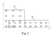
- Fig. 3 represents an example of a crosspolar interferer frame overlapping in the time and frequency planes with the useful data frame at the receiver side.
- the horizontal axis represents the time plane and the vertical axis represents the frequency plane.
- a first frame 31 is sent on one polarization, and a second frame 32 is sent on a second polarization by the satellite Sat.
- frame 31 is the useful signal intended for the receiver Rec and that frame 32 is intended for another receiver in an adjacent beam.
- the polarized waveform travels through the troposphere, impairments appear, the orthogonality is lost, which leads to crosstalk between the two polarizations and thus the second frame 32 becomes a crosspolar interferer for the first frame 31.
- the frames 31 and 32 may have a different length, as shown in Fig. 3 and may totally or partially overlap each other in the time and/or frequency planes. Both frames 31 and 32 may contain data and pilots.
- the pilot positions of frame 31 are noted x and the pilot positions of frame 32 are noted o.
- the useful frame 31 and the interfering frame 32 are not aligned and the transmission of their respective pilot sequences is not coordinated.
- the two frames have different start/end positions in the time plane and they occupy different bandwidths.
- Data/pilots of frame 31 may be interfered by data/pilots of frame 32 or may be interference free.
- the receiver Rec has no prior knowledge of the existence, position or structure of the interfering frame 32.
- Fig. 4 represents an algorithm executed by the receiver Rec according to the present invention. More precisely, the present algorithm is executed by the processor 200 of the receiver Rec.
- the processor 200 obtains the transmit antenna gains a 1 Tx and a 2 Tx at the satellite Sat side.
- the wireless interface 205 detects simultaneously both polarizations.
- s 1 is the symbol transmitted by the satellite Sat on one polarization and intended for the receiver Rec
- h 1 is the channel experienced by the symbol transmitted from the satellite Sat on said polarization and received by the receiver Rec
- A is the crosspolar attenuation
- n 1 , n 2 represent the additive white Gaussian noise of variance ⁇ n 2 on the two receive antennas.
- Atmospheric attenuation b is the atmospheric attenuation due to atmospheric conditions. Atmospheric attenuation b is quasi-static and is given by the atmospheric conditions in the reception area. Atmospheric attenuation b is thus the same for both polarizations.
- Crosspolar attenuation A depends on the atmospheric attenuation b.
- the antenna gains a 1 and a 2 are different for the two polarizations.
- the transmit antenna patterns may be different for the two polarizations.
- the signal intended to the receiver Rec is received in the direction of the main lobe of the satellite antenna for one polarization, while the crosspolar interfering signal may be received in the direction of a secondary lobe, the main lobe of the crosspolar transmission creating the adjacent beam.
- the satellite Sat antenna transmit pattern creates at the terrestrial surface a footprint.
- a fixed receiver Rec is able to know the satellite footprint corresponding to its location, and is thus able to know the transmit antenna gains a 1 Tx and a 2 Tx at the satellite Sat side, via a map or other information provided by the satellite operator and stored in the RAM memory 203.
- the transmit antenna gains value a 1 Tx and a 2 Tx at the satellite Sat side are quasi-static for fixed receivers and are to be updated only in case of changes in the configuration of the satellite beams, or a change of position of the receiver Rec for example.
- Periodic or on-request updates transmit antenna gains values a 1 Tx and a 2 Tx may be executed by the processor 200.
- the same reasoning stands for the attenuation due to free space propagation loss between the satellite Sat and the receiver Rec.
- the processor 200 obtains the receive antenna gains a 1 Rx , a 2 Rx of the receiver Rec.
- the receiving antennas Ant1 and Ant2 characteristics are known by the processor 200 and stored in the ROM memory 202, as they are a build-in parameter, but the receive antenna gains a 1 Rx , a 2 Rx may vary in function of the quality of the antennas alignment for example.
- the processor 200 is able to estimate or acquire knowledge of receive antenna gains a 1 Rx , a 2 Rx during a calibration phase. Such a calibration may occur, for example, at each position change of the receiver Rec, or on regular basis.
- the processor 200 estimates the useful channel h ⁇ 1 using any classical channel estimation methods, as, for example, based on pilot symbols.
- the processor 200 computes the estimated value b ⁇ of the atmospheric attenuation b .
- the transmitted useful signal is a known training sequence z.
- the receiver Rec has no knowledge of the nature of the interfering signal transmitted on the same positions.
- the processor 200 may use empirical curves giving average crosspolar attenuation values in function of the carrier frequency and of the atmospheric attenuation b in order to compute the estimated value ⁇ of the crosspolar attenuation.
- the processor 200 computes the estimated value h ⁇ 2 of the interferer channel.
- the processor 200 estimates the interferer's power ⁇ ⁇ s 2 2 .
- ⁇ X 2 is the variance of X when X has zero mean
- ⁇ 1 , ⁇ 2 are models estimation errors.
- the processor 200 has thus computed estimated values of the useful channel, interferer channel and interferer power, and has knowledge of the noise variance.
- the processor 200 moves to step S408 and checks if the two estimates ⁇ ⁇ n ⁇ 2 and ⁇ ⁇ n ⁇ 2 are consistent.
- noise variance does not change during a received frame
- several individual values ⁇ ⁇ n 2 may be further averaged together in order to improve the reliability of the estimated value of the noise variance.
- the processor 200 has thus computed estimated values of the useful channel, interferer channel, interferer power and noise variance. The processor 200 moves then to step S409.
- the processor 200 determines that the estimation errors are too high and decides not to apply any interference mitigation techniques.
- the processor 200 interrupts the present algorithm.
- the processor 200 may compute at step S408 the estimated value of the noise variance following the exact same procedure as described here-above in the case where the noise variance is not known.
- step S409 if the estimated value ⁇ ⁇ n 2 is consistent with the known value ⁇ n 2 the processor 200 decides that estimation errors are negligible and proceeds to implementing interference mitigation techniques. The processor 200 moves then to step S409.
- the processor 200 determines that the estimation errors are too high and decides not to apply any interference mitigation techniques.
- the processor 200 interrupts the present algorithm.
- the receiver Rec is able to implement interference mitigation techniques such as, for example, joint minimum mean square error (MMSE) detection.
- MMSE joint minimum mean square error
Landscapes
- Engineering & Computer Science (AREA)
- Computer Networks & Wireless Communication (AREA)
- Signal Processing (AREA)
- Physics & Mathematics (AREA)
- Quality & Reliability (AREA)
- Electromagnetism (AREA)
- Astronomy & Astrophysics (AREA)
- Aviation & Aerospace Engineering (AREA)
- General Physics & Mathematics (AREA)
- Noise Elimination (AREA)
- Variable-Direction Aerials And Aerial Arrays (AREA)
Abstract
- obtaining the antenna gains between the satellite transmitter and the receiver,
- estimating a value of the atmospheric attenuation between the satellite transmitter and the receiver, a crosspolar attenuation, the channels between the first and second transmit antennas and the receiver,
- estimating the power of the at least one interferer from the obtained antennas gains and estimations.
Description
- The present invention relates generally to a method and a device for determining a power of at least one crosspolar interferer in a frame received by a receiver.
- In satellite communication systems, multibeam satellites are used for increasing the system capacity. In order to improve the frequency reuse factor without significantly increasing the interference, adjacent beams usually make use of the same frequency with different polarizations. In the adjacent beams, independent signals may be transmitted onto the same frequency band by means of two orthogonal polarizations, like for example horizontal and vertical polarizations. Impairments appear when the polarized waveform travels through the troposphere. Besides waveform attenuation, rain and ice depolarization effects are also present and the orthogonality may be lost, which leads to crosstalk between the two polarizations.
- The severity of this effect depends on the operating frequency, atmospheric conditions, correct antenna calibration/alignment, etc.
- Crosspolar interference causes performance degradation for the users able to receive both signals.
- Mitigation techniques may be employed in order to reduce crosspolar interference. Many such techniques already exist in the literature, for example, joint minimum mean square error detection, with or without successive interference cancellation, turbo receivers.
- The existence and the nature of the interferer need to be known in order for the mitigation techniques to be efficient.
- Transmissions from a satellite to receivers on different polarizations are usually not coordinated. For a given receiver, the useful and the interfering signal frames may be not aligned, i.e. frames have different start/end positions in the time plane and they potentially occupy different bandwidths, pilot positions are different between the interfering frames, etc.
- The present invention aims at determining, in received signals, if crosspolar interference mitigation needs to be performed. To that end, the present invention concerns a method for determining a power of at least one crosspolar interferer in a frame received by a receiver comprising at least a first and a second receive antennas detecting a first and a second polarization, the frame being transmitted from a satellite transmitter comprising at least a first and a second transmit antennas, the first transmit antenna being used for transferring signal representative of the frames to the receiver on the first polarization, the second transmit antenna being used for transferring signal to another receiver using the same frequency and the second polarization, characterized in that the method comprises the steps of:
- obtaining the antenna gains between the satellite transmitter and the receiver,
- estimating an atmospheric attenuation between the satellite transmitter and the receiver,
- estimating a crosspolar attenuation,
- estimating the channel between the first transmit antenna and the receiver taking into account that the channel is static during the transfer of the frame,
- estimating the channel between the second transmit antenna and the receiver from the antenna gain between the second transmit antenna and the receiver and from the atmospheric attenuation,
- estimating the power of the at least one interferer from the obtained antennas gains and estimations.
- The present invention concerns also a device for determining a power of at least one crosspolar interferer in a frame received by a receiver comprising at least a first and a second receive antennas detecting a first and a second polarization, the frame being transmitted from a satellite transmitter comprising at least a first and a second transmit antennas, the first transmit antenna being used for transferring signal representative of the frames to the receiver on the first polarization, the second transmit antenna being used for transferring signal to another receiver using the same frequency and the second polarization, characterized in that the device comprises:
- means for obtaining the antenna gains between the satellite transmitter and the receiver,
- means for estimating an atmospheric attenuation between the satellite transmitter and the receiver,
- means for estimating a crosspolar attenuation,
- means for estimating the channel between the first transmit antenna and the receiver taking into account that the channel is static during the transfer of the frame,
- estimating the channel between the second transmit antenna and the receiver from the antenna gain between the second transmit antenna and the receiver and from the atmospheric attenuation,
- means for estimating the power of the at least one interferer from the obtained antennas gains and estimations.
- Thus, the receiver is able to implement interference mitigation schemes.
- According to a particular feature, the antenna gains between the satellite transmitter and the receiver are obtained from information related to the location of the receiver, related to the satellite transmitter and related to the receiver antenna gains.
- Thus, antenna gains can be obtained at the receiver.
- According to a particular feature, the estimated value of the atmospheric attenuation is computed based on signals received by the receiver through the first receive antenna on pilot symbol positions in the frame transferred by the satellite transmitter through the first transmit antenna.
- Thus, the atmospheric attenuation can be estimated at the receiver.
- According to a particular feature, the estimated value of the atmospheric attenuation is determined according to the following formula:

where E{.} is the mean value computed on at most all the pilot symbol positions in the frame, z denotes pilot symbols, * denotes the complex conjugate, y 1' is the signal received by the receiver through the first receive antenna on pilot symbol positions in the frame transferred by the satellite transmitter through the first transmit antenna, and a 1 is the antenna gain between the first transmit antenna and the first receive antenna. - Thus, the estimated value of the atmospheric attenuation can be computed based on received signals and on known pilot sequence and pilot symbol positions.
- According to a particular feature, the estimated value of the atmospheric attenuation is determined according to the following formula:

where a1 is the antenna gain between the first transmit antenna and the first receive antenna and h̃ 1 is the estimated value of the channel between the first transmit antenna and the receiver. - Thus, the estimated value of the atmospheric attenuation can be computed based on classical channel estimation methods.
- According to a particular feature, the estimated value of the crosspolar attenuation is computed based on the estimated value of the atmospheric attenuation.
- Thus, the estimated value of the crosspolar attenuation can be computed without prior knowledge of the parameters of the crosspolar interferer.
- According to a particular feature, the estimated crosspolar attenuation is

where y2' is the signal received by the receiver through the second receive antenna on pilot symbol positions in the frame transferred by the satellite transmitter through the first transmit antenna. - Thus, the estimated value of the crosspolar attenuation can be computed based on received signals and prior estimations.
- According to a particular feature, the estimated crosspolar attenuation is

- Or

where y2' is the signal received by the receiver through the second receive antenna on pilot symbol positions in the frame transferred by the satellite transmitter through the first transmit antenna. - Thus, the estimated value of the crosspolar attenuation can be computed based only on received signals.
- According to a particular feature, the estimated interferer power is

where a2 is the antenna gain between the second transmit antenna and the second receive antenna, the averaging function E{.} operates over several subcarriers/time slots of the frame during which the nature of the interference does not change and
- Thus, the receiver is able to estimate the power of a crosspolar interferer without any prior knowledge of the interferer's parameters (e.g. modulation and coding scheme, pilot positions, pilot sequence...).
- According to a particular feature,the estimated interferer power is:

where a 2 is the antenna gain between the second transmit antenna and the second receive antenna, the averaging function E{.} operates over several subcarriers/time slots during which the nature of the interference does not change. - Thus, the receiver is able to estimate the power of a crosspolar interferer without any prior knowledge of the interferer's parameters or of the additive white Gaussian noise on the antennas of the receiver.
- According to a particular feature, the estimated value of the channel between the second transmit antenna and the receiver h̃ 2 is estimated by computing:

where a2 is the antenna gain between the second transmit antenna and the second receive antenna and b̃ is the estimated value of the atmospheric attenuation. - Thus, based on the particular nature of the channel between the satellite and the receiver Rec, the present invention is able to estimate the quality of the interfering channel, without prior knowledge of the interferer and without any interference mitigation schemes implemented at the transmitter side.
- According to a particular feature, the method comprises further steps of:
- checking the reliability of the estimated interferer power,
- implementing interference mitigation techniques if the estimated interferer power is reliable.
- Thus, complexity is reduced by implementing interference mitigation only when the interferer is reliably estimated.
- According to still another aspect, the present invention concerns computer programs which can be directly loadable into a programmable device, comprising instructions or portions of code for implementing the steps of the method according to the invention, when said computer programs are executed on a programmable device.
- Since the features and advantages relating to the computer programs are the same as those set out above related to the method and device according to the invention, they will not be repeated here.
- The characteristics of the invention will emerge more clearly from a reading of the following description of example embodiments, the said description being produced with reference to the accompanying drawings, among which :
-
Fig. 1 represents a multi-beam transmission performed by a satellite ; -
Fig. 2 is a diagram representing the architecture of a receiver in which the present invention is implemented ; -
Fig. 3 represents an example of a crosspolar interferer frame overlapping in the time and frequency planes with the useful data frame at the receiver side; -
Fig. 4 represents an algorithm executed by the receiver Rec according to the present invention. -
Fig. 1 represents a multi-beam transmission performed by a satellite. - In the example of
Fig. 1 , a satellite Sat performs a multi-beam transmission on two different frequency bands using different polarizations. - The beams filed with vertical solid lines are on a first frequency band and at a first polarization, the beams filed with vertical dotted lines are on a second frequency band and at the first polarization, the beams filed with horizontal solid lines are on the second frequency band and at the second polarization and the beams filed with horizontal dotted lines are on the first frequency band and at the second polarization.
- When beams are overlapping and use the same frequency band with different polarizations and impairments appear when the polarized waveform travels through the troposphere, the orthogonality may be lost, which leads to crosstalk between the two polarizations. Crosspolar interference causes performance degradation at the receiver side.
- According to the example of
Fig. 1 , the area Int is a zone wherein beams use the same frequency band with different polarizations and are overlapping. - According to the invention, a receiver Rec, not shown in
Fig. 1 : - obtains the antenna gains between the satellite transmitter and the receiver,
- estimates an atmospheric attenuation between the satellite transmitter and the receiver taking into account that the atmospheric attenuation is quasi static and dependent on atmospheric conditions in the area the receiver is located,
- estimates a crosspolar attenuation,
- estimates the channel between the first antenna and the receiver taking into account that the channel is static during the transfer of the frame,
- estimates the channel between the second antenna and the receiver from the antenna gain between the second antenna and the receiver and from the atmospheric attenuation,
- estimates the interferer power from the obtained antennas gains and estimations.
-
Fig. 2 is a diagram representing the architecture of a receiver in which the present invention is implemented. - The receiver Rec has, for example, an architecture based on components connected together by a
bus 201 and aprocessor 200 controlled by the programs as disclosed inFig. 4 . - The
bus 201 links theprocessor 200 to a read onlymemory ROM 202, a randomaccess memory RAM 203 and awireless interface 205. - The
memory 203 contains registers intended to receive variables and the instructions of the programs related to the algorithm as disclosed inFig. 4 . - The
processor 200 controls the operation of thewireless interface 205. - The read only
memory 202 contains instructions of the programs related to the algorithm as disclosed inFig. 4 , which are transferred, when the receiver Rec is powered on, to therandom access memory 203. - The
wireless interface 205 comprises two antennas Ant1 and Ant2 capable of detecting the two different polarizations. - Any and all steps of the algorithms described hereafter with regard to
Fig. 4 may be implemented in software by execution of a set of instructions or program by a programmable computing machine, such as a PC (Personal Computer), a DSP (Digital Signal Processor) or a microcontroller; or else implemented in hardware by a machine or a dedicated component, such as an FPGA (Field-Programmable Gate Array) or an ASIC (Application-Specific Integrates Circuit). - In other words, the receiver Rec includes circuitry, or a device including circuitry, causing the receiver Rec to perform the steps of the algorithm described hereafter with regard to
Fig. 4 . -
Fig. 3 represents an example of a crosspolar interferer frame overlapping in the time and frequency planes with the useful data frame at the receiver side. - The horizontal axis represents the time plane and the vertical axis represents the frequency plane.
- A
first frame 31 is sent on one polarization, and asecond frame 32 is sent on a second polarization by the satellite Sat. - Without loss of generality, let us assume that
frame 31 is the useful signal intended for the receiver Rec and thatframe 32 is intended for another receiver in an adjacent beam. When the polarized waveform travels through the troposphere, impairments appear, the orthogonality is lost, which leads to crosstalk between the two polarizations and thus thesecond frame 32 becomes a crosspolar interferer for thefirst frame 31. - The
frames Fig. 3 and may totally or partially overlap each other in the time and/or frequency planes. Both frames 31 and 32 may contain data and pilots. The pilot positions offrame 31 are noted x and the pilot positions offrame 32 are noted o. - The
useful frame 31 and the interferingframe 32 are not aligned and the transmission of their respective pilot sequences is not coordinated. The two frames have different start/end positions in the time plane and they occupy different bandwidths. Data/pilots offrame 31 may be interfered by data/pilots offrame 32 or may be interference free. The receiver Rec has no prior knowledge of the existence, position or structure of the interferingframe 32. -
Fig. 4 represents an algorithm executed by the receiver Rec according to the present invention. More precisely, the present algorithm is executed by theprocessor 200 of the receiver Rec. - At step S400, the
processor 200 obtains the transmit antenna gains a 1 Tx and a 2 Tx at the satellite Sat side. - The
wireless interface 205 detects simultaneously both polarizations. In the absence of an interferer, the received signal on the two polarizations may be written as: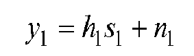

where s 1 is the symbol transmitted by the satellite Sat on one polarization and intended for the receiver Rec, h 1 is the channel experienced by the symbol transmitted from the satellite Sat on said polarization and received by the receiver Rec, A is the crosspolar attenuation and n 1 , n 2 represent the additive white Gaussian noise of variance
- In the presence of an interferer, the above equation rewrites as


where s 2 is the interfering symbol transmitted by the satellite Sat on the second polarization intended for another receiver and h 2 is the channel experienced by the interfering symbol transmitted from the satellite Sat on the other polarization and received by the receiver Rec. - The channel between the satellite Sat and the receiver Rec is supposed static during the transmission. Since the receiver Rec is at a given and stable position and in line of sight with the satellite Sat, the channel between the satellite Sat and the receiver Rec can be decomposed as:
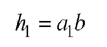

where a 1 and a 2 represent antenna gains and b is the attenuation due to atmospheric conditions. Since for a given receiver Rec not moving during the transmission, the distance between the satellite Sat and the receiver Rec does not change, the free space propagation loss between the satellite Sat and the receiver Rec is known and may be omitted in the following. It can be considered as included either in the antenna gains or in the atmospheric attenuation. This propagation loss will not be mentioned explicitly any longer and it is omitted in the following. - b is the atmospheric attenuation due to atmospheric conditions. Atmospheric attenuation b is quasi-static and is given by the atmospheric conditions in the reception area. Atmospheric attenuation b is thus the same for both polarizations. Crosspolar attenuation A depends on the atmospheric attenuation b.
- The antenna gains a 1 and a 2 are different for the two polarizations.
- Each of them are composed of a transmit antenna gain a i Tx at the satellite Sat side depending on the radiation pattern on the satellite Sat and a receive antenna gain


- For example, the signal intended to the receiver Rec is received in the direction of the main lobe of the satellite antenna for one polarization, while the crosspolar interfering signal may be received in the direction of a secondary lobe, the main lobe of the crosspolar transmission creating the adjacent beam.
- The satellite Sat antenna transmit pattern creates at the terrestrial surface a footprint.
- A fixed receiver Rec is able to know the satellite footprint corresponding to its location, and is thus able to know the transmit antenna gains


RAM memory 203. - The transmit antenna gains value


- Periodic or on-request updates transmit antenna gains values


processor 200. The same reasoning stands for the attenuation due to free space propagation loss between the satellite Sat and the receiver Rec. - At next step S401, the
processor 200 obtains the receive antenna gains
- The receiving antennas Ant1 and Ant2 characteristics are known by the
processor 200 and stored in theROM memory 202, as they are a build-in parameter, but the receive antenna gains
- The
processor 200 is able to estimate or acquire knowledge of receive antenna gains
- Usually,

- At next step S402, the
processor 200 computes

- At next step S403, the
processor 200 estimates the useful channel h̃ 1 using any classical channel estimation methods, as, for example, based on pilot symbols. - At next step S404, the
processor 200 computes the estimated value b̃ of the atmospheric attenuation b. - On pilot positions, the transmitted useful signal is a known training sequence z. The receiver Rec has no knowledge of the nature of the interfering signal transmitted on the same positions. The
processor 200 computes, on pilot positions:

where E{.} is the mean value, z denotes pilot symbols and * denotes the complex conjugate. These average values may be computed including at most all the pilot symbols in the received frame. Less positions may be considered in order to reduce the number of computations. In that case, a sufficient number of pilot symbols needs to be averaged in order for the statistic to be reliable. Theprocessor 200 can thus calculate the estimated value b̃ of atmospheric attenuation b as:
- In a variant, the estimated value b̃ of atmospheric attenuation b can also be computed as:

- At next step S405, the
processor 200 computes the estimated value à of the crosspolar attenuation A as:
- Another means of computing the estimated value à of the crosspolar attenuation is to compute:

or to compute
- In the absence of a second receive antenna, the
processor 200 may use empirical curves giving average crosspolar attenuation values in function of the carrier frequency and of the atmospheric attenuation b in order to compute the estimated value à of the crosspolar attenuation. - At next step S406, the
processor 200 computes the estimated value h̃ 2 of the interferer channel. - Based on the particular nature of the channel between the satellite Sat and the receiver Rec, the
processor 200 is able to estimate the quality of the interfering channel, without prior knowledge of the interferer and without any interference mitigation schemes implemented at the transmitter side as
- At next step S407, the
processor 200 estimates the interferer's power
- From the received signal on pilot positions and using the estimates computed here-above, the
processor 200 computes:

where
- If the noise variance is known_and the estimation errors ε 1, ε 2 are assumed negligible, the estimated value of the interferer power may be computed as

where the averaging function E{.} operates over several subcarriers/time slots during which the nature of the interference does not change. - The
processor 200 has thus computed estimated values of the useful channel, interferer channel and interferer power, and has knowledge of the noise variance. - If the noise variance is not known, the interference power may be estimated as:

where the averaging function E{.} operates over several subcarriers/time slots during which the nature of the interference does not change. - According to a particular mode of realization of the present invention, the
processor 200 may use the estimated value of the interference power in order to compute in two different manners the estimated value of the noise variance:

- When the noise variance is not known, the
processor 200 moves to step S408 and checks if the two estimates

- If the two estimates


processor 200 determines that the suppositions here-above were correct, that estimation errors are negligible and theprocessor 200 determines a reliable estimated value of the noise variance as:
- Since the noise variance does not change during a received frame, several individual values

- The
processor 200 has thus computed estimated values of the useful channel, interferer channel, interferer power and noise variance. Theprocessor 200 moves then to step S409. - If the two estimates


processor 200 determines that the estimation errors are too high and decides not to apply any interference mitigation techniques. Theprocessor 200 interrupts the present algorithm. - According to a particular mode of realization, when the noise variance

processor 200 may compute at step S408 the estimated value of the noise variance following the exact same procedure as described here-above in the case where the noise variance is not known. - As a supplementary reliability check, if the estimated value


processor 200 decides that estimation errors are negligible and proceeds to implementing interference mitigation techniques. Theprocessor 200 moves then to step S409. - If the estimated value


processor 200 determines that the estimation errors are too high and decides not to apply any interference mitigation techniques. Theprocessor 200 interrupts the present algorithm. - At step S409, the receiver Rec is able to implement interference mitigation techniques such as, for example, joint minimum mean square error (MMSE) detection. It has to be noted here that, without further knowledge on the interferer, the receiver Rec is not able to estimate the interferer stream or apply successive interference cancellation, but the receiver Rec is able to improve the detection of the useful signal.
- Naturally, many modifications can be made to the embodiments of the invention described above without departing from the scope of the present invention.
Claims (13)
- Method for determining a power of at least one crosspolar interferer in a frame received by a receiver comprising at least a first and a second receive antennas detecting a first and a second polarization, the frame being transmitted from a satellite transmitter comprising at least a first and a second transmit antennas, the first transmit antenna being used for transferring signal representative of the frames to the receiver on the first polarization, the second transmit antenna being used for transferring signal to another receiver using the same frequency and the second polarization, characterized in that the method comprises the steps of:- obtaining the antenna gains between the satellite transmitter and the receiver,- estimating a value of the atmospheric attenuation between the satellite transmitter and the receiver,- estimating a value of the crosspolar attenuation,- estimating the channel between the first transmit antenna and the receiver taking into account that the channel is static during the transfer of the frame,- estimating the channel between the second transmit antenna and the receiver from the antenna gain between the second transmit antenna and the receiver and from the estimated atmospheric attenuation,- estimating the power of the at least one interferer from the obtained antennas gains and estimations.
- Method according to claim 1, characterized in that the antenna gains between the satellite transmitter and the receiver are obtained from information related to the location of the receiver, related to the satellite transmitter and related to the characteristics of the receiver antennas.
- Method according to claim 1 or 2, characterized in that the estimated value of the atmospheric attenuation is computed based on signals received by the receiver through the first receive antenna on pilot symbol positions in the frame transferred by the satellite transmitter through the first transmit antenna.
- Method according to claim 3, characterized in that the estimated value of the atmospheric attenuation is determined according to the following formula:

where E{.} is the mean value computed on at most all the pilot symbol positions in the frame, z denotes pilot symbols, * denotes the complex conjugate, y 1' is the signal received by the receiver through the first receive antenna on pilot symbol positions in the frame transferred by the satellite transmitter through the first transmit antenna, and a 1 is the antenna gain between the first transmit antenna and the first receive antenna. - Method according to claim 3, characterized in that the estimated value of the atmospheric attenuation is determined according to the following formula:

where a 1 is the antenna gain between the first transmit antenna and the first receive antenna and h̃ 1 is the estimated value of the channel between the first transmit antenna and the receiver. - Method according to claim 3, 4 or 5, characterized in that the estimated value of the crosspolar attenuation is computed based on the estimated value of the atmospheric attenuation.
- Method according to claim 6, characterized in that the estimated value of the crosspolar attenuation is computed as:

where y 2' is the signal received by the receiver through the second receive antenna on positions corresponding to pilot symbol positions in the frame transferred by the satellite transmitter through the first transmit antenna. - Method according to claim 1 or 2, characterized in that the estimated value of the crosspolar attenuation is computed as

Or
where y 1' is the signal received by the receiver through the first receive antenna on pilot symbol positions in the frame, y 2' is the signal received by the receiver through the second receive antenna on positions corresponding to pilot symbol positions in the frame transferred by the satellite transmitter through the first transmit antenna and h̃ 1 is the estimated value of the channel between the first transmit antenna and the receiver. - Method according to any of the claims 1 to 8, characterized in that the estimated interferer power is

where a 2 is the antenna gain between the second transmit antenna and the second receive antenna, the averaging function E{.} operates over several subcarriers/time slots of the frame during which the nature of the interference does not change and
- Method according to any of the claims 1 to 8, characterized in that the estimated interferer power is

where a 2 is the antenna gain between the second transmit antenna and the second receive antenna, the averaging function E{.} operates over several subcarriers/time slots during which the nature of the interference does not change. - Method according to any of the claims 1 to 5, characterized in that the estimated value of the channel between the second transmit antenna and the receiver h̃ 2 is estimated by computing:

where a 2 is the antenna gain between the second transmit antenna and the second receive antenna and b̃ is the estimated value of the atmospheric attenuation. - Method according to claim 1, characterized in that the method comprises further steps of:- checking the reliability of the estimated interferer power,- implementing interference mitigation techniques if the estimated interferer power is reliable.
- Device for determining a power of at least one crosspolar interferer in a frame received by a receiver comprising at least a first and a second receive antennas detecting a first and a second polarization, the frame being transmitted from a satellite transmitter comprising at least a first and a second transmit antennas, the first transmit antenna being used for transferring signal representative of the frames to the receiver on the first polarization, the second transmit antenna being used for transferring signal to another receiver using the same frequency and the second polarization, characterized in that the device comprises:- means for obtaining the antenna gains between the satellite transmitter and the receiver,- means for estimating a value of the atmospheric attenuation between the satellite transmitter and the receiver,- means for estimating a value of the crosspolar attenuation,- means for estimating the channel between the first transmit antenna and the receiver taking into account that the channel is static during the transfer of the frame,- means for estimating the channel between the second transmit antenna and the receiver from the antenna gain between the second transmit antenna and the receiver and from the estimated atmospheric attenuation,- means for estimating the power of the at least one interferer from the obtained antennas gains and estimations.
Priority Applications (4)
| Application Number | Priority Date | Filing Date | Title |
|---|---|---|---|
| EP14195089.9A EP3026825B1 (en) | 2014-11-27 | 2014-11-27 | Method and device for estimating at a receiver the interference between two signals transmitted by a satellite by two antennas using the same frequency and a different polarization. |
| PCT/JP2015/083301 WO2016084920A1 (en) | 2014-11-27 | 2015-11-19 | Method and device for estimating at a receiver the interference between two signals transmitted by a satellite by two antennas using the same frequency and a different polarization. |
| JP2017503980A JP6336197B6 (en) | 2014-11-27 | 2015-11-19 | Method and device for estimating interference at a receiver between two signals transmitted by two antennas using the same frequency and different polarizations by a satellite |
| US15/504,285 US10256927B2 (en) | 2014-11-27 | 2015-11-19 | Method and device for determining power of at least one crosspolar interferer in frame |
Applications Claiming Priority (1)
| Application Number | Priority Date | Filing Date | Title |
|---|---|---|---|
| EP14195089.9A EP3026825B1 (en) | 2014-11-27 | 2014-11-27 | Method and device for estimating at a receiver the interference between two signals transmitted by a satellite by two antennas using the same frequency and a different polarization. |
Publications (2)
| Publication Number | Publication Date |
|---|---|
| EP3026825A1 true EP3026825A1 (en) | 2016-06-01 |
| EP3026825B1 EP3026825B1 (en) | 2018-05-09 |
Family
ID=52011025
Family Applications (1)
| Application Number | Title | Priority Date | Filing Date |
|---|---|---|---|
| EP14195089.9A Not-in-force EP3026825B1 (en) | 2014-11-27 | 2014-11-27 | Method and device for estimating at a receiver the interference between two signals transmitted by a satellite by two antennas using the same frequency and a different polarization. |
Country Status (4)
| Country | Link |
|---|---|
| US (1) | US10256927B2 (en) |
| EP (1) | EP3026825B1 (en) |
| JP (1) | JP6336197B6 (en) |
| WO (1) | WO2016084920A1 (en) |
Cited By (1)
| Publication number | Priority date | Publication date | Assignee | Title |
|---|---|---|---|---|
| CN111711509A (en) * | 2020-04-26 | 2020-09-25 | 四川润泽经伟信息技术有限公司 | Intelligent user interference system and method based on satellite communication countermeasure |
Citations (4)
| Publication number | Priority date | Publication date | Assignee | Title |
|---|---|---|---|---|
| US5901343A (en) * | 1997-05-09 | 1999-05-04 | Lockheed Martin Corporation | Adaptive cross polarization Interference canceler for use at intermediate frequencies |
| WO2008066968A2 (en) * | 2006-06-30 | 2008-06-05 | Rf Magic, Inc. | Satellite interference canceling |
| US20090086862A1 (en) * | 2007-10-01 | 2009-04-02 | Viasat, Inc. | Digital cross-polar interference cancellation |
| US20120188880A1 (en) * | 2012-01-31 | 2012-07-26 | Comtech Ef Data Corp. | Method and System for Performing Multi-Layer, Multi-Dimensional Link Budget Analysis (LBA) Using Real-Time Network, Weather, Satellite Ephemeras and Ionospheric Information |
Family Cites Families (5)
| Publication number | Priority date | Publication date | Assignee | Title |
|---|---|---|---|---|
| JPH0548568A (en) * | 1991-03-19 | 1993-02-26 | Fujitsu Ltd | Cross polarization interference canceller |
| JP4246895B2 (en) * | 2000-08-15 | 2009-04-02 | 日本無線株式会社 | Cross polarization interference measurement circuit |
| US20030224723A1 (en) * | 2002-05-30 | 2003-12-04 | Feng-Wen Sun | Method and system for providing two-way communication using an overlay of signals over a non-linear communications channel |
| JP2011059078A (en) * | 2009-09-14 | 2011-03-24 | Toshiba Corp | Dual polarization radar apparatus and interference determining method |
| US8780787B2 (en) * | 2011-09-12 | 2014-07-15 | Intelsat Corporation | System and method for canceling co-channel interference on-board a satellite |
-
2014
- 2014-11-27 EP EP14195089.9A patent/EP3026825B1/en not_active Not-in-force
-
2015
- 2015-11-19 JP JP2017503980A patent/JP6336197B6/en not_active Expired - Fee Related
- 2015-11-19 US US15/504,285 patent/US10256927B2/en not_active Expired - Fee Related
- 2015-11-19 WO PCT/JP2015/083301 patent/WO2016084920A1/en not_active Ceased
Patent Citations (4)
| Publication number | Priority date | Publication date | Assignee | Title |
|---|---|---|---|---|
| US5901343A (en) * | 1997-05-09 | 1999-05-04 | Lockheed Martin Corporation | Adaptive cross polarization Interference canceler for use at intermediate frequencies |
| WO2008066968A2 (en) * | 2006-06-30 | 2008-06-05 | Rf Magic, Inc. | Satellite interference canceling |
| US20090086862A1 (en) * | 2007-10-01 | 2009-04-02 | Viasat, Inc. | Digital cross-polar interference cancellation |
| US20120188880A1 (en) * | 2012-01-31 | 2012-07-26 | Comtech Ef Data Corp. | Method and System for Performing Multi-Layer, Multi-Dimensional Link Budget Analysis (LBA) Using Real-Time Network, Weather, Satellite Ephemeras and Ionospheric Information |
Cited By (2)
| Publication number | Priority date | Publication date | Assignee | Title |
|---|---|---|---|---|
| CN111711509A (en) * | 2020-04-26 | 2020-09-25 | 四川润泽经伟信息技术有限公司 | Intelligent user interference system and method based on satellite communication countermeasure |
| CN111711509B (en) * | 2020-04-26 | 2023-04-28 | 四川润泽经伟信息技术有限公司 | Intelligent user interference system and method based on satellite communication countermeasure |
Also Published As
| Publication number | Publication date |
|---|---|
| US10256927B2 (en) | 2019-04-09 |
| JP6336197B2 (en) | 2018-06-06 |
| US20170244502A1 (en) | 2017-08-24 |
| JP6336197B6 (en) | 2018-07-25 |
| WO2016084920A1 (en) | 2016-06-02 |
| JP2017528046A (en) | 2017-09-21 |
| EP3026825B1 (en) | 2018-05-09 |
Similar Documents
| Publication | Publication Date | Title |
|---|---|---|
| US8626069B2 (en) | Apparatus and method for beamforming considering interference amount in broadband wireless communication system | |
| US9014149B2 (en) | Communication apparatus and base station apparatus | |
| KR101401598B1 (en) | Apparatus and method for interference cancellation in multiple antenna system | |
| KR100675489B1 (en) | Multi Antenna Communication System Implementing Signal Correction Apparatus and Method | |
| US9516528B2 (en) | Method for estimating interference within a serving cell, user equipment, computer program and computer program products | |
| US20140119308A1 (en) | Wireless communication apparatus | |
| EP3229384A1 (en) | A communications calibration sub-system, a system and a method | |
| US9584198B1 (en) | Reciprocity calibration for multiple-input multiple-output systems | |
| US8351955B2 (en) | Method and device for determining antenna cooperation set, method and device for determining base station cooperation set | |
| EP3766180B1 (en) | Millimeter wave (mmwave) system and methods | |
| KR20100034838A (en) | Apparatus and method for calibration for relay station in multiple antenna system | |
| KR20160048360A (en) | method and apparatus for receiving a signal based on a measurement of interference | |
| RU2439826C2 (en) | Radio transmission system and method for compensating for cross-talk | |
| Temiz et al. | A receiver architecture for dual-functional massive MIMO OFDM RadCom systems | |
| EP4280474A1 (en) | Communication relay device, system, interference suppression method, and program | |
| US20180109003A1 (en) | Method of generating circularly polarised signals from a polarisation controller of a ground station | |
| US20230403073A1 (en) | Transmission of atmospheric ducted communication signals | |
| EP3026825B1 (en) | Method and device for estimating at a receiver the interference between two signals transmitted by a satellite by two antennas using the same frequency and a different polarization. | |
| US9872294B2 (en) | Base station, radio communications system, and processing method in base station | |
| US10103905B2 (en) | Method for transmitting channel information and wireless communication system using the same | |
| US11949473B2 (en) | Wireless receiving apparatus, wireless communication system, and wireless receiving method | |
| US9929797B2 (en) | Method and device for determining if at least one interferer generated by cross polarization interference is present in received frame | |
| KR101267799B1 (en) | Apparatus and method for canceling inter symbol interference of othogonal coded signal in mobile communication system | |
| EP4066411B1 (en) | Near-capacity iterative detection of co-channel interference for a high-efficiency multibeam satellite system | |
| US11456798B2 (en) | IMU-assisted polarization division multiplexed MIMO wireless communication |
Legal Events
| Date | Code | Title | Description |
|---|---|---|---|
| PUAI | Public reference made under article 153(3) epc to a published international application that has entered the european phase |
Free format text: ORIGINAL CODE: 0009012 |
|
| AK | Designated contracting states |
Kind code of ref document: A1 Designated state(s): AL AT BE BG CH CY CZ DE DK EE ES FI FR GB GR HR HU IE IS IT LI LT LU LV MC MK MT NL NO PL PT RO RS SE SI SK SM TR |
|
| AX | Request for extension of the european patent |
Extension state: BA ME |
|
| 17P | Request for examination filed |
Effective date: 20161129 |
|
| RBV | Designated contracting states (corrected) |
Designated state(s): AL AT BE BG CH CY CZ DE DK EE ES FI FR GB GR HR HU IE IS IT LI LT LU LV MC MK MT NL NO PL PT RO RS SE SI SK SM TR |
|
| 17Q | First examination report despatched |
Effective date: 20170221 |
|
| REG | Reference to a national code |
Ref country code: DE Ref legal event code: R079 Ref document number: 602014025140 Country of ref document: DE Free format text: PREVIOUS MAIN CLASS: H04B0007185000 Ipc: H04B0017309000 |
|
| GRAP | Despatch of communication of intention to grant a patent |
Free format text: ORIGINAL CODE: EPIDOSNIGR1 |
|
| RIC1 | Information provided on ipc code assigned before grant |
Ipc: H04B 7/185 20060101ALI20171020BHEP Ipc: H04B 17/309 20150101AFI20171020BHEP Ipc: H04B 7/00 20060101ALI20171020BHEP |
|
| INTG | Intention to grant announced |
Effective date: 20171128 |
|
| GRAS | Grant fee paid |
Free format text: ORIGINAL CODE: EPIDOSNIGR3 |
|
| GRAA | (expected) grant |
Free format text: ORIGINAL CODE: 0009210 |
|
| AK | Designated contracting states |
Kind code of ref document: B1 Designated state(s): AL AT BE BG CH CY CZ DE DK EE ES FI FR GB GR HR HU IE IS IT LI LT LU LV MC MK MT NL NO PL PT RO RS SE SI SK SM TR |
|
| REG | Reference to a national code |
Ref country code: GB Ref legal event code: FG4D |
|
| REG | Reference to a national code |
Ref country code: CH Ref legal event code: EP Ref country code: AT Ref legal event code: REF Ref document number: 998459 Country of ref document: AT Kind code of ref document: T Effective date: 20180515 |
|
| REG | Reference to a national code |
Ref country code: IE Ref legal event code: FG4D |
|
| REG | Reference to a national code |
Ref country code: DE Ref legal event code: R096 Ref document number: 602014025140 Country of ref document: DE |
|
| REG | Reference to a national code |
Ref country code: NL Ref legal event code: MP Effective date: 20180509 |
|
| REG | Reference to a national code |
Ref country code: LT Ref legal event code: MG4D |
|
| PG25 | Lapsed in a contracting state [announced via postgrant information from national office to epo] |
Ref country code: SE Free format text: LAPSE BECAUSE OF FAILURE TO SUBMIT A TRANSLATION OF THE DESCRIPTION OR TO PAY THE FEE WITHIN THE PRESCRIBED TIME-LIMIT Effective date: 20180509 Ref country code: ES Free format text: LAPSE BECAUSE OF FAILURE TO SUBMIT A TRANSLATION OF THE DESCRIPTION OR TO PAY THE FEE WITHIN THE PRESCRIBED TIME-LIMIT Effective date: 20180509 Ref country code: LT Free format text: LAPSE BECAUSE OF FAILURE TO SUBMIT A TRANSLATION OF THE DESCRIPTION OR TO PAY THE FEE WITHIN THE PRESCRIBED TIME-LIMIT Effective date: 20180509 Ref country code: BG Free format text: LAPSE BECAUSE OF FAILURE TO SUBMIT A TRANSLATION OF THE DESCRIPTION OR TO PAY THE FEE WITHIN THE PRESCRIBED TIME-LIMIT Effective date: 20180809 Ref country code: NO Free format text: LAPSE BECAUSE OF FAILURE TO SUBMIT A TRANSLATION OF THE DESCRIPTION OR TO PAY THE FEE WITHIN THE PRESCRIBED TIME-LIMIT Effective date: 20180809 Ref country code: FI Free format text: LAPSE BECAUSE OF FAILURE TO SUBMIT A TRANSLATION OF THE DESCRIPTION OR TO PAY THE FEE WITHIN THE PRESCRIBED TIME-LIMIT Effective date: 20180509 |
|
| PG25 | Lapsed in a contracting state [announced via postgrant information from national office to epo] |
Ref country code: GR Free format text: LAPSE BECAUSE OF FAILURE TO SUBMIT A TRANSLATION OF THE DESCRIPTION OR TO PAY THE FEE WITHIN THE PRESCRIBED TIME-LIMIT Effective date: 20180810 Ref country code: HR Free format text: LAPSE BECAUSE OF FAILURE TO SUBMIT A TRANSLATION OF THE DESCRIPTION OR TO PAY THE FEE WITHIN THE PRESCRIBED TIME-LIMIT Effective date: 20180509 Ref country code: RS Free format text: LAPSE BECAUSE OF FAILURE TO SUBMIT A TRANSLATION OF THE DESCRIPTION OR TO PAY THE FEE WITHIN THE PRESCRIBED TIME-LIMIT Effective date: 20180509 Ref country code: LV Free format text: LAPSE BECAUSE OF FAILURE TO SUBMIT A TRANSLATION OF THE DESCRIPTION OR TO PAY THE FEE WITHIN THE PRESCRIBED TIME-LIMIT Effective date: 20180509 Ref country code: NL Free format text: LAPSE BECAUSE OF FAILURE TO SUBMIT A TRANSLATION OF THE DESCRIPTION OR TO PAY THE FEE WITHIN THE PRESCRIBED TIME-LIMIT Effective date: 20180509 |
|
| REG | Reference to a national code |
Ref country code: AT Ref legal event code: MK05 Ref document number: 998459 Country of ref document: AT Kind code of ref document: T Effective date: 20180509 |
|
| PG25 | Lapsed in a contracting state [announced via postgrant information from national office to epo] |
Ref country code: PL Free format text: LAPSE BECAUSE OF FAILURE TO SUBMIT A TRANSLATION OF THE DESCRIPTION OR TO PAY THE FEE WITHIN THE PRESCRIBED TIME-LIMIT Effective date: 20180509 Ref country code: SK Free format text: LAPSE BECAUSE OF FAILURE TO SUBMIT A TRANSLATION OF THE DESCRIPTION OR TO PAY THE FEE WITHIN THE PRESCRIBED TIME-LIMIT Effective date: 20180509 Ref country code: CZ Free format text: LAPSE BECAUSE OF FAILURE TO SUBMIT A TRANSLATION OF THE DESCRIPTION OR TO PAY THE FEE WITHIN THE PRESCRIBED TIME-LIMIT Effective date: 20180509 Ref country code: AT Free format text: LAPSE BECAUSE OF FAILURE TO SUBMIT A TRANSLATION OF THE DESCRIPTION OR TO PAY THE FEE WITHIN THE PRESCRIBED TIME-LIMIT Effective date: 20180509 Ref country code: DK Free format text: LAPSE BECAUSE OF FAILURE TO SUBMIT A TRANSLATION OF THE DESCRIPTION OR TO PAY THE FEE WITHIN THE PRESCRIBED TIME-LIMIT Effective date: 20180509 Ref country code: RO Free format text: LAPSE BECAUSE OF FAILURE TO SUBMIT A TRANSLATION OF THE DESCRIPTION OR TO PAY THE FEE WITHIN THE PRESCRIBED TIME-LIMIT Effective date: 20180509 Ref country code: EE Free format text: LAPSE BECAUSE OF FAILURE TO SUBMIT A TRANSLATION OF THE DESCRIPTION OR TO PAY THE FEE WITHIN THE PRESCRIBED TIME-LIMIT Effective date: 20180509 |
|
| REG | Reference to a national code |
Ref country code: DE Ref legal event code: R097 Ref document number: 602014025140 Country of ref document: DE |
|
| PG25 | Lapsed in a contracting state [announced via postgrant information from national office to epo] |
Ref country code: SM Free format text: LAPSE BECAUSE OF FAILURE TO SUBMIT A TRANSLATION OF THE DESCRIPTION OR TO PAY THE FEE WITHIN THE PRESCRIBED TIME-LIMIT Effective date: 20180509 Ref country code: IT Free format text: LAPSE BECAUSE OF FAILURE TO SUBMIT A TRANSLATION OF THE DESCRIPTION OR TO PAY THE FEE WITHIN THE PRESCRIBED TIME-LIMIT Effective date: 20180509 |
|
| PLBE | No opposition filed within time limit |
Free format text: ORIGINAL CODE: 0009261 |
|
| STAA | Information on the status of an ep patent application or granted ep patent |
Free format text: STATUS: NO OPPOSITION FILED WITHIN TIME LIMIT |
|
| 26N | No opposition filed |
Effective date: 20190212 |
|
| PG25 | Lapsed in a contracting state [announced via postgrant information from national office to epo] |
Ref country code: SI Free format text: LAPSE BECAUSE OF FAILURE TO SUBMIT A TRANSLATION OF THE DESCRIPTION OR TO PAY THE FEE WITHIN THE PRESCRIBED TIME-LIMIT Effective date: 20180509 |
|
| REG | Reference to a national code |
Ref country code: CH Ref legal event code: PL |
|
| PG25 | Lapsed in a contracting state [announced via postgrant information from national office to epo] |
Ref country code: LU Free format text: LAPSE BECAUSE OF NON-PAYMENT OF DUE FEES Effective date: 20181127 Ref country code: MC Free format text: LAPSE BECAUSE OF FAILURE TO SUBMIT A TRANSLATION OF THE DESCRIPTION OR TO PAY THE FEE WITHIN THE PRESCRIBED TIME-LIMIT Effective date: 20180509 |
|
| REG | Reference to a national code |
Ref country code: BE Ref legal event code: MM Effective date: 20181130 |
|
| REG | Reference to a national code |
Ref country code: IE Ref legal event code: MM4A |
|
| PG25 | Lapsed in a contracting state [announced via postgrant information from national office to epo] |
Ref country code: LI Free format text: LAPSE BECAUSE OF NON-PAYMENT OF DUE FEES Effective date: 20181130 Ref country code: CH Free format text: LAPSE BECAUSE OF NON-PAYMENT OF DUE FEES Effective date: 20181130 |
|
| PG25 | Lapsed in a contracting state [announced via postgrant information from national office to epo] |
Ref country code: IE Free format text: LAPSE BECAUSE OF NON-PAYMENT OF DUE FEES Effective date: 20181127 |
|
| PG25 | Lapsed in a contracting state [announced via postgrant information from national office to epo] |
Ref country code: BE Free format text: LAPSE BECAUSE OF NON-PAYMENT OF DUE FEES Effective date: 20181130 Ref country code: AL Free format text: LAPSE BECAUSE OF FAILURE TO SUBMIT A TRANSLATION OF THE DESCRIPTION OR TO PAY THE FEE WITHIN THE PRESCRIBED TIME-LIMIT Effective date: 20180509 |
|
| PG25 | Lapsed in a contracting state [announced via postgrant information from national office to epo] |
Ref country code: MT Free format text: LAPSE BECAUSE OF NON-PAYMENT OF DUE FEES Effective date: 20181127 |
|
| PG25 | Lapsed in a contracting state [announced via postgrant information from national office to epo] |
Ref country code: TR Free format text: LAPSE BECAUSE OF FAILURE TO SUBMIT A TRANSLATION OF THE DESCRIPTION OR TO PAY THE FEE WITHIN THE PRESCRIBED TIME-LIMIT Effective date: 20180509 |
|
| PG25 | Lapsed in a contracting state [announced via postgrant information from national office to epo] |
Ref country code: PT Free format text: LAPSE BECAUSE OF FAILURE TO SUBMIT A TRANSLATION OF THE DESCRIPTION OR TO PAY THE FEE WITHIN THE PRESCRIBED TIME-LIMIT Effective date: 20180509 |
|
| PG25 | Lapsed in a contracting state [announced via postgrant information from national office to epo] |
Ref country code: CY Free format text: LAPSE BECAUSE OF FAILURE TO SUBMIT A TRANSLATION OF THE DESCRIPTION OR TO PAY THE FEE WITHIN THE PRESCRIBED TIME-LIMIT Effective date: 20180509 Ref country code: MK Free format text: LAPSE BECAUSE OF NON-PAYMENT OF DUE FEES Effective date: 20180509 Ref country code: HU Free format text: LAPSE BECAUSE OF FAILURE TO SUBMIT A TRANSLATION OF THE DESCRIPTION OR TO PAY THE FEE WITHIN THE PRESCRIBED TIME-LIMIT; INVALID AB INITIO Effective date: 20141127 |
|
| PG25 | Lapsed in a contracting state [announced via postgrant information from national office to epo] |
Ref country code: IS Free format text: LAPSE BECAUSE OF FAILURE TO SUBMIT A TRANSLATION OF THE DESCRIPTION OR TO PAY THE FEE WITHIN THE PRESCRIBED TIME-LIMIT Effective date: 20180909 |
|
| REG | Reference to a national code |
Ref country code: GB Ref legal event code: 746 Effective date: 20200824 |
|
| REG | Reference to a national code |
Ref country code: DE Ref legal event code: R084 Ref document number: 602014025140 Country of ref document: DE |
|
| PGFP | Annual fee paid to national office [announced via postgrant information from national office to epo] |
Ref country code: DE Payment date: 20211005 Year of fee payment: 8 Ref country code: FR Payment date: 20211109 Year of fee payment: 8 Ref country code: GB Payment date: 20211007 Year of fee payment: 8 |
|
| REG | Reference to a national code |
Ref country code: DE Ref legal event code: R119 Ref document number: 602014025140 Country of ref document: DE |
|
| GBPC | Gb: european patent ceased through non-payment of renewal fee |
Effective date: 20221127 |
|
| PG25 | Lapsed in a contracting state [announced via postgrant information from national office to epo] |
Ref country code: GB Free format text: LAPSE BECAUSE OF NON-PAYMENT OF DUE FEES Effective date: 20221127 Ref country code: DE Free format text: LAPSE BECAUSE OF NON-PAYMENT OF DUE FEES Effective date: 20230601 |
|
| PG25 | Lapsed in a contracting state [announced via postgrant information from national office to epo] |
Ref country code: FR Free format text: LAPSE BECAUSE OF NON-PAYMENT OF DUE FEES Effective date: 20221130 |