EP3026772A1 - Battery overcharge preventing device - Google Patents
Battery overcharge preventing device Download PDFInfo
- Publication number
- EP3026772A1 EP3026772A1 EP14829094.3A EP14829094A EP3026772A1 EP 3026772 A1 EP3026772 A1 EP 3026772A1 EP 14829094 A EP14829094 A EP 14829094A EP 3026772 A1 EP3026772 A1 EP 3026772A1
- Authority
- EP
- European Patent Office
- Prior art keywords
- unit
- battery
- voltage
- preventing device
- input voltage
- Prior art date
- Legal status (The legal status is an assumption and is not a legal conclusion. Google has not performed a legal analysis and makes no representation as to the accuracy of the status listed.)
- Granted
Links
Images




Classifications
-
- H—ELECTRICITY
- H01—ELECTRIC ELEMENTS
- H01M—PROCESSES OR MEANS, e.g. BATTERIES, FOR THE DIRECT CONVERSION OF CHEMICAL ENERGY INTO ELECTRICAL ENERGY
- H01M10/00—Secondary cells; Manufacture thereof
- H01M10/42—Methods or arrangements for servicing or maintenance of secondary cells or secondary half-cells
- H01M10/44—Methods for charging or discharging
- H01M10/441—Methods for charging or discharging for several batteries or cells simultaneously or sequentially
-
- G—PHYSICS
- G01—MEASURING; TESTING
- G01R—MEASURING ELECTRIC VARIABLES; MEASURING MAGNETIC VARIABLES
- G01R15/00—Details of measuring arrangements of the types provided for in groups G01R17/00 - G01R29/00, G01R33/00 - G01R33/26 or G01R35/00
- G01R15/04—Voltage dividers
-
- H—ELECTRICITY
- H01—ELECTRIC ELEMENTS
- H01M—PROCESSES OR MEANS, e.g. BATTERIES, FOR THE DIRECT CONVERSION OF CHEMICAL ENERGY INTO ELECTRICAL ENERGY
- H01M10/00—Secondary cells; Manufacture thereof
- H01M10/42—Methods or arrangements for servicing or maintenance of secondary cells or secondary half-cells
- H01M10/48—Accumulators combined with arrangements for measuring, testing or indicating the condition of cells, e.g. the level or density of the electrolyte
- H01M10/482—Accumulators combined with arrangements for measuring, testing or indicating the condition of cells, e.g. the level or density of the electrolyte for several batteries or cells simultaneously or sequentially
-
- H—ELECTRICITY
- H01—ELECTRIC ELEMENTS
- H01M—PROCESSES OR MEANS, e.g. BATTERIES, FOR THE DIRECT CONVERSION OF CHEMICAL ENERGY INTO ELECTRICAL ENERGY
- H01M50/00—Constructional details or processes of manufacture of the non-active parts of electrochemical cells other than fuel cells, e.g. hybrid cells
- H01M50/20—Mountings; Secondary casings or frames; Racks, modules or packs; Suspension devices; Shock absorbers; Transport or carrying devices; Holders
- H01M50/204—Racks, modules or packs for multiple batteries or multiple cells
-
- H—ELECTRICITY
- H01—ELECTRIC ELEMENTS
- H01M—PROCESSES OR MEANS, e.g. BATTERIES, FOR THE DIRECT CONVERSION OF CHEMICAL ENERGY INTO ELECTRICAL ENERGY
- H01M50/00—Constructional details or processes of manufacture of the non-active parts of electrochemical cells other than fuel cells, e.g. hybrid cells
- H01M50/50—Current conducting connections for cells or batteries
- H01M50/569—Constructional details of current conducting connections for detecting conditions inside cells or batteries, e.g. details of voltage sensing terminals
-
- H—ELECTRICITY
- H01—ELECTRIC ELEMENTS
- H01M—PROCESSES OR MEANS, e.g. BATTERIES, FOR THE DIRECT CONVERSION OF CHEMICAL ENERGY INTO ELECTRICAL ENERGY
- H01M50/00—Constructional details or processes of manufacture of the non-active parts of electrochemical cells other than fuel cells, e.g. hybrid cells
- H01M50/50—Current conducting connections for cells or batteries
- H01M50/572—Means for preventing undesired use or discharge
- H01M50/574—Devices or arrangements for the interruption of current
-
- H—ELECTRICITY
- H02—GENERATION; CONVERSION OR DISTRIBUTION OF ELECTRIC POWER
- H02H—EMERGENCY PROTECTIVE CIRCUIT ARRANGEMENTS
- H02H7/00—Emergency protective circuit arrangements specially adapted for specific types of electric machines or apparatus or for sectionalised protection of cable or line systems, and effecting automatic switching in the event of an undesired change from normal working conditions
- H02H7/18—Emergency protective circuit arrangements specially adapted for specific types of electric machines or apparatus or for sectionalised protection of cable or line systems, and effecting automatic switching in the event of an undesired change from normal working conditions for batteries; for accumulators
-
- H—ELECTRICITY
- H02—GENERATION; CONVERSION OR DISTRIBUTION OF ELECTRIC POWER
- H02J—ELECTRIC POWER NETWORKS; CIRCUIT ARRANGEMENTS OR SYSTEMS FOR SUPPLYING OR DISTRIBUTING ELECTRIC POWER; SYSTEMS FOR STORING ELECTRIC ENERGY
- H02J7/00—Circuit arrangements for charging or discharging batteries or for supplying loads from batteries
- H02J7/50—Circuit arrangements for charging or discharging batteries or for supplying loads from batteries acting upon multiple batteries simultaneously or sequentially
-
- H—ELECTRICITY
- H02—GENERATION; CONVERSION OR DISTRIBUTION OF ELECTRIC POWER
- H02J—ELECTRIC POWER NETWORKS; CIRCUIT ARRANGEMENTS OR SYSTEMS FOR SUPPLYING OR DISTRIBUTING ELECTRIC POWER; SYSTEMS FOR STORING ELECTRIC ENERGY
- H02J7/00—Circuit arrangements for charging or discharging batteries or for supplying loads from batteries
- H02J7/60—Circuit arrangements for charging or discharging batteries or for supplying loads from batteries including safety or protection arrangements
- H02J7/64—Circuit arrangements for charging or discharging batteries or for supplying loads from batteries including safety or protection arrangements against overvoltage
-
- H—ELECTRICITY
- H02—GENERATION; CONVERSION OR DISTRIBUTION OF ELECTRIC POWER
- H02J—ELECTRIC POWER NETWORKS; CIRCUIT ARRANGEMENTS OR SYSTEMS FOR SUPPLYING OR DISTRIBUTING ELECTRIC POWER; SYSTEMS FOR STORING ELECTRIC ENERGY
- H02J7/00—Circuit arrangements for charging or discharging batteries or for supplying loads from batteries
- H02J7/60—Circuit arrangements for charging or discharging batteries or for supplying loads from batteries including safety or protection arrangements
- H02J7/65—Circuit arrangements for charging or discharging batteries or for supplying loads from batteries including safety or protection arrangements against overtemperature
-
- H—ELECTRICITY
- H02—GENERATION; CONVERSION OR DISTRIBUTION OF ELECTRIC POWER
- H02J—ELECTRIC POWER NETWORKS; CIRCUIT ARRANGEMENTS OR SYSTEMS FOR SUPPLYING OR DISTRIBUTING ELECTRIC POWER; SYSTEMS FOR STORING ELECTRIC ENERGY
- H02J7/00—Circuit arrangements for charging or discharging batteries or for supplying loads from batteries
- H02J7/60—Circuit arrangements for charging or discharging batteries or for supplying loads from batteries including safety or protection arrangements
- H02J7/663—Circuit arrangements for charging or discharging batteries or for supplying loads from batteries including safety or protection arrangements using battery or load disconnect circuits
-
- H—ELECTRICITY
- H01—ELECTRIC ELEMENTS
- H01M—PROCESSES OR MEANS, e.g. BATTERIES, FOR THE DIRECT CONVERSION OF CHEMICAL ENERGY INTO ELECTRICAL ENERGY
- H01M10/00—Secondary cells; Manufacture thereof
- H01M10/42—Methods or arrangements for servicing or maintenance of secondary cells or secondary half-cells
- H01M10/425—Structural combination with electronic components, e.g. electronic circuits integrated to the outside of the casing
- H01M2010/4271—Battery management systems including electronic circuits, e.g. control of current or voltage to keep battery in healthy state, cell balancing
-
- H—ELECTRICITY
- H02—GENERATION; CONVERSION OR DISTRIBUTION OF ELECTRIC POWER
- H02J—ELECTRIC POWER NETWORKS; CIRCUIT ARRANGEMENTS OR SYSTEMS FOR SUPPLYING OR DISTRIBUTING ELECTRIC POWER; SYSTEMS FOR STORING ELECTRIC ENERGY
- H02J7/00—Circuit arrangements for charging or discharging batteries or for supplying loads from batteries
- H02J7/60—Circuit arrangements for charging or discharging batteries or for supplying loads from batteries including safety or protection arrangements
- H02J7/61—Circuit arrangements for charging or discharging batteries or for supplying loads from batteries including safety or protection arrangements against overcharge
-
- Y—GENERAL TAGGING OF NEW TECHNOLOGICAL DEVELOPMENTS; GENERAL TAGGING OF CROSS-SECTIONAL TECHNOLOGIES SPANNING OVER SEVERAL SECTIONS OF THE IPC; TECHNICAL SUBJECTS COVERED BY FORMER USPC CROSS-REFERENCE ART COLLECTIONS [XRACs] AND DIGESTS
- Y02—TECHNOLOGIES OR APPLICATIONS FOR MITIGATION OR ADAPTATION AGAINST CLIMATE CHANGE
- Y02E—REDUCTION OF GREENHOUSE GAS [GHG] EMISSIONS, RELATED TO ENERGY GENERATION, TRANSMISSION OR DISTRIBUTION
- Y02E60/00—Enabling technologies; Technologies with a potential or indirect contribution to GHG emissions mitigation
- Y02E60/10—Energy storage using batteries
Definitions
- the present invention relates to a battery overcharge preventing device, and more particularly, to a battery overcharge preventing device capable of sensing an over-voltage using a voltage of a battery cell as input power of a passive element and cutting off power supplied to a battery at the time of overcharge of the battery.
- An existing runaway arrest device sensing and cutting off overcharge of a battery of an electrically driven vehicle senses whether or not the battery is overcharged using a swelling phenomenon that a battery cell is swelled when the battery is overcharged.
- the RAD is configured to include a switch disposed on a side surface of the battery cell, wherein the switch is physically pushed by a swelling displacement amount of the side surface of the battery cell to sense whether or not the battery is overcharged.
- the RAD may be configured so that the switch is connected to a relay control line controlling power of the battery in series to cut off the power supplied to the battery when the battery is overcharged or notify a battery management system (BMS) of an abnormal phenomenon through a high voltage interlock loop (HVIL) sensing a binding state of the battery, thereby cutting off the power supplied to the battery.
- BMS battery management system
- HVIL high voltage interlock loop
- the RAD depends on the swelling phenomenon occurring when the battery is overcharged
- the swelling phenomenon of the battery cell is a phenomenon irregularly occurring according to characteristics of the battery itself, it may be difficult to accurately sense whether or not the battery is overcharged.
- the switch positioned on the side surface of the battery cell and the battery cell should be configured to have a constant interval therebetween, which is difficult, the possibility of a malfunction due to external impact, or the like, is present, and a space in which the switch is mounted is required on the side surface of the battery cell in order to sense the swelling of the side surface of the battery cell.
- an existing current interrupt device sensing and cutting off the overcharge of the battery of the electrically driven vehicle has a configuration in which a tab part of the battery cell is cut so that the battery cell deviates from an original position using the swelling phenomenon of the battery cell when the battery is overcharged.
- the CID has a weak point mechanically formed intentionally in order to operate sensitively to the swelling phenomenon of the battery cell occurring when the battery is overcharged, it has a disadvantage that mechanical reliability is decreased and a disadvantage that a space in which a device is mounted is required on the side surface of the battery cell in order to sense the swelling phenomenon of the battery cell, as in the RAD.
- U.S. Patent Application Publication No. 2011-0298463 has disclosed a battery state monitoring circuit and a battery device.
- An object of the present invention is to provide a battery overcharge preventing device capable of sensing overcharge by an electrical change and cutting off power supplied to a battery at the time of the overcharge of the battery using a passive element.
- an overcharge preventing device includes: an input voltage dividing unit connected across at least one battery cell in a battery pack including a plurality of battery cells and dividing a voltage of the battery cell; a voltage sensing unit connected to the input voltage dividing unit and operated when it is sensed that a voltage input through the input voltage dividing unit is a predetermined voltage or more; and a power cut-off unit connected to the voltage sensing unit and turning on or turning off an internal switch by the operation of the voltage sensing unit to cut off power supplied to the battery pack.
- the power cut-off unit may include coil units and a switch unit, the voltage sensing unit may be connected to the coil unit, a line of a relay coil side controlled by a battery management system (BMS) may be connected to the switch unit, and the switch unit may cut off an electrical connection to cut off power of the line of the relay coil side when power is applied to the coil unit by the operation of the voltage sensing unit.
- BMS battery management system
- the input voltage dividing unit may include a plurality of resistors connected to each other in series.
- the voltage sensing unit may be configured of a shunt regulator, an anode of the shunt regulator may be connected between the resistors of the input voltage dividing unit, a cathode of the shunt regulator may be connected to a positive electrode of the battery cell to which the input voltage dividing unit is connected, a reference of the shunt regulator may be connected to a negative electrode of the battery cell to which the input voltage dividing unit is connected, and the cathode and the reference of the shunt regulator may be electrically conducted to each other when an input voltage divided using the input voltage dividing unit is input as a predetermined voltage or more.
- the power cut-off unit may include coil units and a switch unit, one side of the coil unit may be connected to the positive electrode of the battery cell to which the input voltage dividing unit is connected and the other side thereof may be connected to the cathode of the shunt regulator, and one side of the switch unit may be connected to a line of a relay coil side controlled by a battery management system (BMS) and the other side thereof may be connected to a common line (-).
- BMS battery management system
- the power cut-off unit may be configured of a non-return circuit operating the switch unit when the power is applied to the coil unit by the operation of the voltage sensing unit and maintaining an operation state as it is until before a separate control is performed.
- the power cut-off unit may be configured of a latching relay.
- the power cut-off unit may include a resistor connected to the coil units in parallel between the coil units of the power cut-off unit.
- the overcharge preventing device may further include a safety unit connected across the battery cell or to the anode of the shunt regulator and the reference of the shunt regulator.
- the safety unit may be at least any one of a capacitor and a TVS diode.
- the battery overcharge preventing device when overcharge is generated during a period in which the battery pack is charged, the power supplied to the battery pack is cut off, thereby making it possible to prevent ignition or explosion.
- the power of the relay coil side controlled by the battery management system is cut off at the time of the overcharge of the battery pack by the power cut-off unit connected to the line of the relay coil side controlled by the battery management system, such that the power supplied to the battery pack is cut off regardless of the control of the battery management system, thereby making it possible to prevent the ignition or the explosion.
- the voltage divided by the input voltage dividing unit is used as an input voltage of the voltage sensing unit, such that the voltage sensing unit may be variously configured.
- the voltage sensing unit configured of the shunt regulator is used to minimize an operation deviation depending on a temperature of the voltage sensing unit, thereby making it possible to improve an operation precision.
- an overcharge sensing circuit and a circuit of the power supplied to the battery pack are separately configured, thereby making it possible to minimize power consumed by the voltage sensing unit at ordinary times.
- the power cut-off unit is configured of the non-return circuit to cut off the power supplied to the battery pack until before a separate control is performed after the overcharge is generated, thereby making it possible to increase stability.
- the power cut-off unit configured of the latching relay since the power cut-off unit configured of the latching relay is used, a separate component of a self hold circuit is not required, such that a size, a cost, and a weight may be decreased.
- noise generated at the time of an operation of the coil units may be decreased by the resistor connected to the coil units of the power cut-off unit in parallel to allow the voltage sensing unit not to be affected by the noise, thereby making it possible to improve a precision of the voltage sensing unit.
- an error rate may be decreased, and an influence of an instantaneous voltage rise on other elements is minimized, thereby making it possible to improve stability and operation reliability.
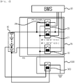
- FIG. 1 is a conceptual diagram of a battery overcharge preventing device according to an exemplary embodiment of the present invention
- FIG. 2 is an illustrative view illustrating a connection of a power cut-off unit of the battery overcharge preventing device according to an exemplary embodiment of the present invention
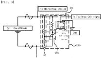
- FIG. 3 is a circuit diagram of the battery overcharge preventing device according to an exemplary embodiment of the present invention
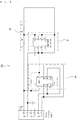
- FIG. 4 is a circuit diagram illustrating a case that is not in an overcharge state in the battery overcharge preventing device according to an exemplary embodiment of the present invention
- FIG. 5 is a circuit diagram illustrating an overcharge state in the battery overcharge preventing device according to an exemplary embodiment of the present invention
- FIG. 1 is a conceptual diagram of a battery overcharge preventing device according to an exemplary embodiment of the present invention
- FIG. 2 is an illustrative view illustrating a connection of a power cut-off unit of the battery overcharge preventing device according to an exemplary embodiment of the present invention
- FIG. 3 is
- FIG. 6 is a circuit diagram illustrating the battery overcharge preventing device including a safety unit according to an exemplary embodiment of the present invention
- FIG. 7 is a circuit diagram illustrating an example of implementing the battery overcharge preventing device according to an exemplary embodiment of the present invention
- FIG. 8 is a circuit diagram illustrating an example of implementing the battery overcharge preventing device including a safety unit according to an exemplary embodiment of the present invention.
- the battery overcharge preventing device 1000 is configured to include an input voltage dividing unit 100, a voltage sensing unit 200, and a power cut-off unit 300.
- a voltage of the battery cell rises, and it may be confirmed whether or not the battery cell is overcharged using a voltage value at the time of overcharge of the battery cell. Therefore, the voltage of the battery cell may be used as input power of a passive element to operate the passive element at a predetermined voltage, thereby cutting off the overcharge.
- the input voltage dividing unit 100 is connected across at least one battery cell in the battery pack 10 including the plurality of battery cells, and divides the voltage of the battery cell.
- a voltage value across the at least one battery cell that may be decided to be the overcharge and a voltage value for operating the passive element may be different from each other.
- the input voltage dividing unit 100 divides an input voltage (the voltage across the at least one battery cell) so that the passive element is operated.
- the input voltage dividing unit 100 is configured to receive the voltage of the at least one battery cell in the battery pack 10 including the plurality of battery cells as the input voltage.
- the input voltage dividing unit 100 may be connected to a battery side so as to receive the voltage of the at least one battery cell in the battery pack 10 including the plurality of battery cells as the input voltage or receive a total voltage of the battery pack 10 as the input voltage.
- several overcharge preventing devices may be configured by configuring several input voltage dividing units such as a first input voltage dividing unit receiving the voltage of the at least one battery cell in the battery pack 10 including the plurality of battery cells as the input voltage, a second input voltage dividing unit receiving the total voltage of the battery pack 10 as the input voltage, and the like, and using a first voltage sensing unit, a second voltage sensing unit, a first power cut-off unit, a second power cut-off unit, and the like, each connected to the several input voltage dividing units. That is, a plurality of battery overcharge preventing devices 1000 may be configured and used.
- FIG. 1 a form in which a solid state relay receives a voltage of a unit battery cell connected to the lowest portion in the battery pack 10 as an input voltage is illustrated by way of example.
- the voltage sensing unit 200 is connected to the input voltage dividing unit 100, and is operated when it is sensed that a voltage input through the input voltage dividing unit is a predetermined voltage or more.
- the power cut-off unit 300 is connected to the voltage sensing unit 200, and turns on or turns off an internal switch by the operation of the voltage sensing unit 200 to cut off power supplied to the battery pack 10.
- the power supplied to the battery pack 10 may be cut off using the power cut-off unit 300. That is, the power supplied to the battery pack 10 is cut off without being affected by an external circuit (battery management system (BMS)), or the like, when the overcharge is generated during a period in which the battery pack 10 is charged, thereby making it possible to prevent ignition or explosion.
- BMS battery management system
- the battery cell 10 may be configured to include a power relay assembly (PRA) 20 connected to the battery cell 10 and a battery management system (BMS) 30 controlling the respective relays included in the power relay assembly 20.
- PRA power relay assembly
- BMS battery management system
- the power relay assembly 20 may be configured to include a first main relay (+) 21, a second main relay 22 (-), a pre-charge relay 23, and a pre-charge resistor 24.
- the first main relay (+) 21 may be connected to a positive electrode terminal of the battery pack 10, and may cut off an electrical connection with the battery pack 10.
- the second main relay (-) 22 may be connected to a negative electrode terminal of the battery pack 10, and may cut off an electrical connection with the battery pack 10.
- the pre-charge resistor 24 and the pre-charge relay 23 allow a current output from the battery pack 10 to be pre-charged before being connected to the first main relay 21. Through this, an arc discharge that may be generated at the time of being directly connected to the first main relay 21 is prevented, thereby making it possible to secure stability of a circuit.
- the pre-charge relay 23 may be connected to the first main relay (+) 21 in parallel, and the pre-charge resistor 24 may be connected to the pre-charge relay 23 in series.
- An electrical connection and disconnection of a general battery pack 10 through the power relay assembly 20 are possible, and the respective relays of the power relay assembly 20 are controlled by the battery management system 30.
- the power cut-off unit 300 may be configured to include coil units and a switch unit.
- the coil unit is connected to the voltage sensing unit 200.
- the voltage sensing unit 200 may apply the power to the coil unit of the power cut-off unit 300.
- the switch unit is connected to a line of a relay coil side controlled by the battery management system 30.
- the switch unit of the power cut-off unit 300 may cut off an electrical connection to cut off the power of the line of the relay coil side. That is, since the power may not be applied to the respective relay coils by cutting off the power of the line of the relay coil side, the control of the respective relays by the battery management system 30 is impossible, and the respective relays are maintained in a state in which the electrical connection is cut off, such that the power supplied to the battery pack 10 is cut off.
- the power of the relay coil side controlled by the battery management system is cut off at the time of the overcharge of the battery pack 10 by the power cut-off unit 300 connected to the line of the relay coil side controlled by the battery management system 30, such that the power supplied to the battery pack 10 is cut off regardless of the control of the battery management system 30, thereby making it possible to prevent the ignition or the explosion without being affected by occurrence of a problem of the battery management system 30.
- the input voltage dividing unit 100 may be configured to include a plurality of resistors connected to each other in series.
- the input voltage dividing unit 100 divides the voltage of the battery cell in order that a voltage used for the operation of the voltage sensing unit 200 may compare with a voltage appearing at the time of the overcharge of the battery cell.
- the voltage appearing at the time of the overcharge of the battery cell is 4.75V and the voltage required for the operation of the voltage sensing unit 200 is 2.5V
- resistors having resistance values of 18K ⁇ and 20K ⁇ are used as illustrated in FIG. 3
- the voltage sensing unit 200 may be operated.
- the voltage (the voltage of the battery cell used for sensing the overcharge) input to the input voltage dividing unit 100 is the voltage at the time of the overcharge
- the voltage may be divided using the plurality of resistors in order to be adjusted to the voltage that may operate the voltage sensing unit 200.
- the plurality of resistors of the input voltage dividing unit 100 that are connected to each other in series may select a battery resistance value depending on whether the input voltage dividing unit 100 receives the voltage of the at least one battery cell as the input voltage or receives the total voltage of the battery pack 10 as the input voltage.
- the voltage divided by the input voltage dividing unit is used as the input voltage of the voltage sensing unit, various kinds of voltages (a voltage of one cell, a voltage of a plurality of cells, a total voltage of the battery pack, and the like) may be used as the input voltage, and the voltage sensing unit may be variously configured (there is no limitation depending on the voltage for operating the voltage sensing unit).
- the voltage sensing unit 200 is configured of a shunt regulator, which may be configured to include anode, cathode, and reference terminals.
- the anode of the shunt regulator is connected between the resistors of the input voltage dividing unit 100, the cathode thereof is connected to the positive electrode of the battery cell to which the input voltage dividing unit 100 is connected, and the reference thereof is connected to the negative electrode of the battery cell to which the input voltage dividing unit 100 is connected.
- the cathode and the reference of the shunt regulator are electrically conducted to each other.
- the cathode and the reference are electrically cut off from each other.
- the cathode and the reference are electrically conducted (operated) to each other.
- a magnitude of a charging voltage of a unit battery cell is 4.2V
- a magnitude of the voltage at which it is sensed that the battery is overcharged is a value between 4.2V and 5V.
- the voltage appearing at the time of the overcharge of the battery cell is 4.75V and the voltage required for the operation of the voltage sensing unit 200 is 2.5V
- the resistors having the resistance values of 18K ⁇ and 20K ⁇ are used as illustrated in FIG. 3
- a value of 2.5V or more is applied to the anode of the shunt regulator, such that the cathode and the reference are electrically conducted (operated) to each other.
- a magnitude of the voltage at which it may be sensed whether or not the battery is overcharged may be determined depending on whether the voltage of the at least one battery cell is received as the input voltage or the total voltage of the battery pack 10 is received as the input voltage.
- the power cut-off unit 300 may be configured to include the coil units and the switch unit.
- One side of the coil unit is connected to the positive electrode of the battery cell to which the input voltage dividing unit 100 is connected, and the other side thereof is connected to the cathode of the shunt regulator.
- One side of the switch unit is connected to the line of the relay coil side controlled by the battery management system (BMS), and the other side thereof is connected to a common line (-).
- BMS battery management system
- the power cut-off unit 300 is connected between the common lines connected to the respective relay coils to cut off the common lines, thereby making it possible to easily cut off the electrical connections of all the relays.
- an overcharge sensing circuit (circuit connected to the coil unit) and a circuit (circuit connected to the switch unit) of the power supplied to the battery pack 10 are separately configured, thereby making it possible to minimize power consumed by the voltage sensing unit at ordinary times.
- the power cut-off unit 300 may be configured of a non-return circuit operating the switch unit when the power is applied to the coil unit by the operation of the voltage sensing unit 200 and maintaining an operation state as it is until before a separate control is performed.
- the non-return circuit which is a component operating the switch unit when the power is applied to the coil unit, maintains the operation state of the switch unit as it is until before the separate control is performed.
- the power cut-off unit configured of the non-return circuit cuts off power supplied to a battery module until before the separate control is performed through the non-return circuit, thereby making it possible to prevent an additional accident from occurring until before the follow-up measure against the overcharge of the battery is performed.
- the power cut-off unit is configured of the non-return circuit to cut off the power supplied to the battery pack 10 until before the separate control is performed after the overcharge is generated, thereby making it possible to increase stability.
- the power cut-off unit 300 may be configured of a latching relay.
- FIG. 3 illustrates a form in which a latching relay element is provided as the power cut-off unit 300.
- the latching relay element is a relay element in which a contact state of a contact is maintained as it is even though a current supplied to the coil is cut off until before the separate control is performed.
- the shunt regulator becomes a state in which it may not be electrically conducted, and the latching relay also maintains an initial state in which the voltage sensing unit 200 is not operated, such that controls of power relays (controls of the first main relay (+), the second main relay (-), and the pre-charge relay) by the battery management system 30 are possible.
- the shunt regulator becomes a state in which it is electrically conducted, and the latching relay is operated to cut off the current supplied to a coil end of the power relay assembly, such that the electrical connections of all of the respective relays (the first main relay (+), the second main relay (-), and the pre-charge relay) are cut off.
- the latching relay After the latching relay is operated on the basis of an overcharge voltage, the latching relay does not return to an initial state (state in which a relay control is possible by the battery management system 30) while continuously maintaining the internal switch in a current state (overcharge cut-off state) until before a separate control is performed.
- the voltage input to the input voltage driving unit 100 may be configured to be transferred to the battery management system 30 until before a separate control is performed, as illustrated in FIG. 3 .
- the battery management system 30 it is possible to inform the battery management system 30 whether or not the battery cell is overcharged regardless of whether or not the relays in the power relay assembly 20 cut off the power.
- An alarm, or the like, is generated so that the overcharge may be recognized in the outside or the inside of a vehicle, thereby making it possible to inform the outside or the inside of the vehicle of the overcharge state sensed as described above.
- a signal for informing the outside of the overcharge state of the battery is continuously provided to the outside until before a separate control is performed on the latching relay, thereby making it possible to prevent an additional accident from occurring until before the follow-up measure against the overcharge of the battery is performed.
- the power cut-off unit configured of the latching relay since the power cut-off unit configured of the latching relay is used, a separate component of a self hold circuit is not required, such that a size, a cost, and a weight may be decreased.
- FIG. 7 illustrates an example of directly implementing the battery overcharge preventing device 1000 using an applicable element.
- Connectors may be mounted on a printed circuit board (PCB) on which only elements configuring the battery overcharge preventing device 1000 are mounted to thereby be connected to the battery cells and the power relay assembly 20, and one unit may be configured and may be mounted at any place in the battery pack 10, such that a layout is free.
- PCB printed circuit board
- elements that may be used in the battery overcharge preventing device 1000 may be mounted and configured on a sensing PCB transferring the voltage of the battery cell to the battery management system 30.
- the battery overcharge preventing device 1000 may be configured without adding a connector by increasing only a required number of pins in an existing sensing PCB connector, such that a size, a manufacturing cost, and a weight of the battery pack may be decreased.
- a position at which the battery overcharge preventing device 1000 according to an exemplary embodiment of the present invention is mounted is not limited to a position such as a voltage sensing PCB, an inner portion of the battery pack 10, or the like.
- the power cut-off unit 300 may be configured to include a resistor connected to the coil units in parallel between the coil units of the power cut-off unit 300.
- Noise generated at the time of an operation of the coil units may be decreased by the resistor connected to the coil units of the power cut-off unit 300 in parallel, and an influence of the voltage sensing unit 200 on the noise is minimized, thereby making it possible to improve a precision of the voltage sensing unit 200.
- the battery overcharge preventing device may be configured to include a safety unit 400 connected across the battery cell or to the anode of the shunt regulator and the reference of the shunt regulator.
- the safety unit 400 may be configured to include at least any one of a capacitor and a TVS diode.
- FIG. 8 illustrates an example of directly implementing the battery overcharge preventing device using an applicable element.
- a function of sensing the overcharge state of the battery may be provided separately from the battery management system 30, thereby making it possible to additionally secure stability of the vehicle and satisfy the ISO26262 standard.
- the present invention is not limited to the above-mentioned exemplary embodiments, and may be variously applied, and may be variously modified without departing from the gist of the present invention claimed in the claims.
Landscapes
- Engineering & Computer Science (AREA)
- Power Engineering (AREA)
- Chemical & Material Sciences (AREA)
- Chemical Kinetics & Catalysis (AREA)
- Electrochemistry (AREA)
- General Chemical & Material Sciences (AREA)
- Manufacturing & Machinery (AREA)
- Physics & Mathematics (AREA)
- General Physics & Mathematics (AREA)
- Charge And Discharge Circuits For Batteries Or The Like (AREA)
- Secondary Cells (AREA)
Abstract
Description
- The present invention relates to a battery overcharge preventing device, and more particularly, to a battery overcharge preventing device capable of sensing an over-voltage using a voltage of a battery cell as input power of a passive element and cutting off power supplied to a battery at the time of overcharge of the battery.
- An existing runaway arrest device (RAD) sensing and cutting off overcharge of a battery of an electrically driven vehicle senses whether or not the battery is overcharged using a swelling phenomenon that a battery cell is swelled when the battery is overcharged. The RAD is configured to include a switch disposed on a side surface of the battery cell, wherein the switch is physically pushed by a swelling displacement amount of the side surface of the battery cell to sense whether or not the battery is overcharged. The RAD may be configured so that the switch is connected to a relay control line controlling power of the battery in series to cut off the power supplied to the battery when the battery is overcharged or notify a battery management system (BMS) of an abnormal phenomenon through a high voltage interlock loop (HVIL) sensing a binding state of the battery, thereby cutting off the power supplied to the battery.
- However, since the RAD depends on the swelling phenomenon occurring when the battery is overcharged, when considering that the swelling phenomenon of the battery cell is a phenomenon irregularly occurring according to characteristics of the battery itself, it may be difficult to accurately sense whether or not the battery is overcharged. In addition, there are problems that several situations should be considered, for example, the switch positioned on the side surface of the battery cell and the battery cell should be configured to have a constant interval therebetween, which is difficult, the possibility of a malfunction due to external impact, or the like, is present, and a space in which the switch is mounted is required on the side surface of the battery cell in order to sense the swelling of the side surface of the battery cell.
- In addition, an existing current interrupt device (CID) sensing and cutting off the overcharge of the battery of the electrically driven vehicle has a configuration in which a tab part of the battery cell is cut so that the battery cell deviates from an original position using the swelling phenomenon of the battery cell when the battery is overcharged.
- However, since the CID has a weak point mechanically formed intentionally in order to operate sensitively to the swelling phenomenon of the battery cell occurring when the battery is overcharged, it has a disadvantage that mechanical reliability is decreased and a disadvantage that a space in which a device is mounted is required on the side surface of the battery cell in order to sense the swelling phenomenon of the battery cell, as in the RAD.
-
U.S. Patent Application Publication No. 2011-0298463 has disclosed a battery state monitoring circuit and a battery device. - An object of the present invention is to provide a battery overcharge preventing device capable of sensing overcharge by an electrical change and cutting off power supplied to a battery at the time of the overcharge of the battery using a passive element.
- In one general aspect, an overcharge preventing device includes: an input voltage dividing unit connected across at least one battery cell in a battery pack including a plurality of battery cells and dividing a voltage of the battery cell; a voltage sensing unit connected to the input voltage dividing unit and operated when it is sensed that a voltage input through the input voltage dividing unit is a predetermined voltage or more; and a power cut-off unit connected to the voltage sensing unit and turning on or turning off an internal switch by the operation of the voltage sensing unit to cut off power supplied to the battery pack.
- The power cut-off unit may include coil units and a switch unit, the voltage sensing unit may be connected to the coil unit, a line of a relay coil side controlled by a battery management system (BMS) may be connected to the switch unit, and the switch unit may cut off an electrical connection to cut off power of the line of the relay coil side when power is applied to the coil unit by the operation of the voltage sensing unit.
- The input voltage dividing unit may include a plurality of resistors connected to each other in series.
- The voltage sensing unit may be configured of a shunt regulator, an anode of the shunt regulator may be connected between the resistors of the input voltage dividing unit, a cathode of the shunt regulator may be connected to a positive electrode of the battery cell to which the input voltage dividing unit is connected, a reference of the shunt regulator may be connected to a negative electrode of the battery cell to which the input voltage dividing unit is connected, and the cathode and the reference of the shunt regulator may be electrically conducted to each other when an input voltage divided using the input voltage dividing unit is input as a predetermined voltage or more.
- The power cut-off unit may include coil units and a switch unit, one side of the coil unit may be connected to the positive electrode of the battery cell to which the input voltage dividing unit is connected and the other side thereof may be connected to the cathode of the shunt regulator, and one side of the switch unit may be connected to a line of a relay coil side controlled by a battery management system (BMS) and the other side thereof may be connected to a common line (-).
- The power cut-off unit may be configured of a non-return circuit operating the switch unit when the power is applied to the coil unit by the operation of the voltage sensing unit and maintaining an operation state as it is until before a separate control is performed.
- The power cut-off unit may be configured of a latching relay.
- The power cut-off unit may include a resistor connected to the coil units in parallel between the coil units of the power cut-off unit.
- The overcharge preventing device may further include a safety unit connected across the battery cell or to the anode of the shunt regulator and the reference of the shunt regulator.
- The safety unit may be at least any one of a capacitor and a TVS diode.
- In the battery overcharge preventing device according to an exemplary embodiment of the present invention, when overcharge is generated during a period in which the battery pack is charged, the power supplied to the battery pack is cut off, thereby making it possible to prevent ignition or explosion.
- In addition, the power of the relay coil side controlled by the battery management system is cut off at the time of the overcharge of the battery pack by the power cut-off unit connected to the line of the relay coil side controlled by the battery management system, such that the power supplied to the battery pack is cut off regardless of the control of the battery management system, thereby making it possible to prevent the ignition or the explosion.
- Further, the voltage divided by the input voltage dividing unit is used as an input voltage of the voltage sensing unit, such that the voltage sensing unit may be variously configured.
- Further, the voltage sensing unit configured of the shunt regulator is used to minimize an operation deviation depending on a temperature of the voltage sensing unit, thereby making it possible to improve an operation precision.
- Further, an overcharge sensing circuit and a circuit of the power supplied to the battery pack are separately configured, thereby making it possible to minimize power consumed by the voltage sensing unit at ordinary times.
- Further, the power cut-off unit is configured of the non-return circuit to cut off the power supplied to the battery pack until before a separate control is performed after the overcharge is generated, thereby making it possible to increase stability.
- Further, since the power cut-off unit configured of the latching relay is used, a separate component of a self hold circuit is not required, such that a size, a cost, and a weight may be decreased.
- Further, noise generated at the time of an operation of the coil units may be decreased by the resistor connected to the coil units of the power cut-off unit in parallel to allow the voltage sensing unit not to be affected by the noise, thereby making it possible to improve a precision of the voltage sensing unit.
- Furthermore, due to the safety unit, an error rate may be decreased, and an influence of an instantaneous voltage rise on other elements is minimized, thereby making it possible to improve stability and operation reliability.
-
-
FIG. 1 is a conceptual diagram of a battery overcharge preventing device according to an exemplary embodiment of the present invention. -
FIG. 2 is an illustrative view illustrating a connection of a power cut-off unit of the battery overcharge preventing device according to an exemplary embodiment of the present invention. -
FIG. 3 is a circuit diagram of the battery overcharge preventing device according to an exemplary embodiment of the present invention. -
FIG. 4 is a circuit diagram illustrating a case that is not in an overcharge state in the battery overcharge preventing device according to an exemplary embodiment of the present invention. -
FIG. 5 is a circuit diagram illustrating an overcharge state in the battery overcharge preventing device according to an exemplary embodiment of the present invention. -
FIG. 6 is a circuit diagram illustrating the battery overcharge preventing device including a safety unit according to an exemplary embodiment of the present invention. -
FIG. 7 is a circuit diagram illustrating an example of implementing the battery overcharge preventing device according to an exemplary embodiment of the present invention. -
FIG. 8 is a circuit diagram illustrating an example of implementing the battery overcharge preventing device including a safety unit according to an exemplary embodiment of the present invention. - Hereinafter, the present invention will be described in detail with reference to the accompanying drawings. It is to be noted that throughout the accompanying drawings, the same components are denoted by the same reference numerals. In addition, a detailed description for the well-known functions and configurations that may unnecessarily make the gist of the present invention unclear will be omitted.
-
FIG. 1 is a conceptual diagram of a battery overcharge preventing device according to an exemplary embodiment of the present invention,FIG. 2 is an illustrative view illustrating a connection of a power cut-off unit of the battery overcharge preventing device according to an exemplary embodiment of the present invention,FIG. 3 is a circuit diagram of the battery overcharge preventing device according to an exemplary embodiment of the present invention,FIG. 4 is a circuit diagram illustrating a case that is not in an overcharge state in the battery overcharge preventing device according to an exemplary embodiment of the present invention,FIG. 5 is a circuit diagram illustrating an overcharge state in the battery overcharge preventing device according to an exemplary embodiment of the present invention,FIG. 6 is a circuit diagram illustrating the battery overcharge preventing device including a safety unit according to an exemplary embodiment of the present invention,FIG. 7 is a circuit diagram illustrating an example of implementing the battery overcharge preventing device according to an exemplary embodiment of the present invention, andFIG. 8 is a circuit diagram illustrating an example of implementing the battery overcharge preventing device including a safety unit according to an exemplary embodiment of the present invention. - As illustrated in
FIG. 1 , the batteryovercharge preventing device 1000 according to an exemplary embodiment of the present invention is configured to include an inputvoltage dividing unit 100, avoltage sensing unit 200, and a power cut-off unit 300. - In a
battery pack 10 including a plurality of battery cells, when overcharge is generated during a period in which thebattery pack 10 is charged, a voltage of the battery cell rises, and it may be confirmed whether or not the battery cell is overcharged using a voltage value at the time of overcharge of the battery cell. Therefore, the voltage of the battery cell may be used as input power of a passive element to operate the passive element at a predetermined voltage, thereby cutting off the overcharge. - The input
voltage dividing unit 100 is connected across at least one battery cell in thebattery pack 10 including the plurality of battery cells, and divides the voltage of the battery cell. - A voltage value across the at least one battery cell that may be decided to be the overcharge and a voltage value for operating the passive element may be different from each other.
- In the case in which the voltage across the at least one battery cell is used as the input power of the passive element, such that it is decided that the voltage across the at least one battery cell is a voltage at the time of the overcharge, the input
voltage dividing unit 100 divides an input voltage (the voltage across the at least one battery cell) so that the passive element is operated. - Here, the input
voltage dividing unit 100 is configured to receive the voltage of the at least one battery cell in thebattery pack 10 including the plurality of battery cells as the input voltage. - In other words, the input
voltage dividing unit 100 may be connected to a battery side so as to receive the voltage of the at least one battery cell in thebattery pack 10 including the plurality of battery cells as the input voltage or receive a total voltage of thebattery pack 10 as the input voltage. In addition, several overcharge preventing devices may be configured by configuring several input voltage dividing units such as a first input voltage dividing unit receiving the voltage of the at least one battery cell in thebattery pack 10 including the plurality of battery cells as the input voltage, a second input voltage dividing unit receiving the total voltage of thebattery pack 10 as the input voltage, and the like, and using a first voltage sensing unit, a second voltage sensing unit, a first power cut-off unit, a second power cut-off unit, and the like, each connected to the several input voltage dividing units. That is, a plurality of batteryovercharge preventing devices 1000 may be configured and used. - In
FIG. 1 , a form in which a solid state relay receives a voltage of a unit battery cell connected to the lowest portion in thebattery pack 10 as an input voltage is illustrated by way of example. - The
voltage sensing unit 200 is connected to the inputvoltage dividing unit 100, and is operated when it is sensed that a voltage input through the input voltage dividing unit is a predetermined voltage or more. - The power cut-off
unit 300 is connected to thevoltage sensing unit 200, and turns on or turns off an internal switch by the operation of thevoltage sensing unit 200 to cut off power supplied to thebattery pack 10. - In other words, when the voltage input to the
voltage sensing unit 200 is a voltage at the time of generation of the overcharge, the power supplied to thebattery pack 10 may be cut off using the power cut-offunit 300. That is, the power supplied to thebattery pack 10 is cut off without being affected by an external circuit (battery management system (BMS)), or the like, when the overcharge is generated during a period in which thebattery pack 10 is charged, thereby making it possible to prevent ignition or explosion. - As illustrated in
FIG. 2 , thebattery cell 10 may be configured to include a power relay assembly (PRA) 20 connected to thebattery cell 10 and a battery management system (BMS) 30 controlling the respective relays included in thepower relay assembly 20. - The
power relay assembly 20 may be configured to include a first main relay (+) 21, a second main relay 22 (-), apre-charge relay 23, and apre-charge resistor 24. - The first main relay (+) 21 may be connected to a positive electrode terminal of the
battery pack 10, and may cut off an electrical connection with thebattery pack 10. - The second main relay (-) 22 may be connected to a negative electrode terminal of the
battery pack 10, and may cut off an electrical connection with thebattery pack 10. - The
pre-charge resistor 24 and thepre-charge relay 23 allow a current output from thebattery pack 10 to be pre-charged before being connected to the firstmain relay 21. Through this, an arc discharge that may be generated at the time of being directly connected to the firstmain relay 21 is prevented, thereby making it possible to secure stability of a circuit. Here, thepre-charge relay 23 may be connected to the first main relay (+) 21 in parallel, and thepre-charge resistor 24 may be connected to thepre-charge relay 23 in series. - An electrical connection and disconnection of a
general battery pack 10 through thepower relay assembly 20 are possible, and the respective relays of thepower relay assembly 20 are controlled by thebattery management system 30. - The power cut-off
unit 300 may be configured to include coil units and a switch unit. - The coil unit is connected to the
voltage sensing unit 200. - Although not illustrated in
FIG. 2 , thevoltage sensing unit 200 may apply the power to the coil unit of the power cut-offunit 300. - The switch unit is connected to a line of a relay coil side controlled by the
battery management system 30. - Here, when the power is applied to the coil unit of the power cut-off
unit 300 by the operation of thevoltage sensing unit 200, the switch unit of the power cut-offunit 300 may cut off an electrical connection to cut off the power of the line of the relay coil side. That is, since the power may not be applied to the respective relay coils by cutting off the power of the line of the relay coil side, the control of the respective relays by thebattery management system 30 is impossible, and the respective relays are maintained in a state in which the electrical connection is cut off, such that the power supplied to thebattery pack 10 is cut off. - In other words, the power of the relay coil side controlled by the battery management system is cut off at the time of the overcharge of the
battery pack 10 by the power cut-offunit 300 connected to the line of the relay coil side controlled by thebattery management system 30, such that the power supplied to thebattery pack 10 is cut off regardless of the control of thebattery management system 30, thereby making it possible to prevent the ignition or the explosion without being affected by occurrence of a problem of thebattery management system 30. - As illustrated in
FIG. 3 , the inputvoltage dividing unit 100 may be configured to include a plurality of resistors connected to each other in series. Here, the inputvoltage dividing unit 100 divides the voltage of the battery cell in order that a voltage used for the operation of thevoltage sensing unit 200 may compare with a voltage appearing at the time of the overcharge of the battery cell. For example, in the case in which the voltage appearing at the time of the overcharge of the battery cell is 4.75V and the voltage required for the operation of thevoltage sensing unit 200 is 2.5V, when resistors having resistance values of 18KΩ and 20KΩ are used as illustrated inFIG. 3 , in the case in which the voltage of the battery cell is 4.75V (the voltage at the time of the overcharge) or more, thevoltage sensing unit 200 may be operated. - In other words, in the case in which the voltage (the voltage of the battery cell used for sensing the overcharge) input to the input
voltage dividing unit 100 is the voltage at the time of the overcharge, the voltage may be divided using the plurality of resistors in order to be adjusted to the voltage that may operate thevoltage sensing unit 200. - The plurality of resistors of the input
voltage dividing unit 100 that are connected to each other in series may select a battery resistance value depending on whether the inputvoltage dividing unit 100 receives the voltage of the at least one battery cell as the input voltage or receives the total voltage of thebattery pack 10 as the input voltage. - Since the voltage divided by the input voltage dividing unit is used as the input voltage of the voltage sensing unit, various kinds of voltages (a voltage of one cell, a voltage of a plurality of cells, a total voltage of the battery pack, and the like) may be used as the input voltage, and the voltage sensing unit may be variously configured (there is no limitation depending on the voltage for operating the voltage sensing unit).
- As illustrated in
FIG. 3 , thevoltage sensing unit 200 is configured of a shunt regulator, which may be configured to include anode, cathode, and reference terminals. - Here, the anode of the shunt regulator is connected between the resistors of the input
voltage dividing unit 100, the cathode thereof is connected to the positive electrode of the battery cell to which the inputvoltage dividing unit 100 is connected, and the reference thereof is connected to the negative electrode of the battery cell to which the inputvoltage dividing unit 100 is connected. - Here, when the input voltage divided using the input
voltage dividing unit 100 is input as a predetermined voltage or more, the cathode and the reference of the shunt regulator are electrically conducted to each other. - As illustrated in
FIG. 4 , in the case in which a voltage smaller than a preset voltage is applied to the anode of the shunt regulator SR, the cathode and the reference are electrically cut off from each other. - As illustrated in
FIG. 5 , in the case in which a voltage larger than a preset voltage is applied to the anode of the shunt regulator SR, the cathode and the reference are electrically conducted (operated) to each other. - Generally, considering that a magnitude of a charging voltage of a unit battery cell is 4.2V, in the case in which the voltage of the unit battery cell is received as the input voltage, as illustrated in
FIG. 3 , a magnitude of the voltage at which it is sensed that the battery is overcharged is a value between 4.2V and 5V. - For example, in the case in which the voltage appearing at the time of the overcharge of the battery cell is 4.75V and the voltage required for the operation of the
voltage sensing unit 200 is 2.5V, when the resistors having the resistance values of 18KΩ and 20KΩ are used as illustrated inFIG. 3 , in the case in which the voltage of the battery cell is a value of 4.75V (the voltage at the time of the overcharge) or more, a value of 2.5V or more is applied to the anode of the shunt regulator, such that the cathode and the reference are electrically conducted (operated) to each other. - Since a deviation of an operating voltage of the shunt regulator depending on an external temperature is significantly smaller than that of a solid state relay (SSR), or the like, it may be applied to an element requiring a high precision, and an operation deviation is minimized using the shunt regulator, thereby making it possible to improve an operation precision.
- A magnitude of the voltage at which it may be sensed whether or not the battery is overcharged may be determined depending on whether the voltage of the at least one battery cell is received as the input voltage or the total voltage of the
battery pack 10 is received as the input voltage. - As illustrated in
FIG. 3 , the power cut-offunit 300 may be configured to include the coil units and the switch unit. - One side of the coil unit is connected to the positive electrode of the battery cell to which the input
voltage dividing unit 100 is connected, and the other side thereof is connected to the cathode of the shunt regulator. - One side of the switch unit is connected to the line of the relay coil side controlled by the battery management system (BMS), and the other side thereof is connected to a common line (-).
- In order to cut off the power supplied to the battery pack, all of the electrical connections to the battery pack need to be cut off. For example, in the case in which the power relay assembly is connected to the battery pack, the electrical connections of the first main relay (+), the second main relay (-), and the pre-charge relay need to be cut off. In order to cut off the electrical connections of all of the respective relays at a time, the power cut-off
unit 300 is connected between the common lines connected to the respective relay coils to cut off the common lines, thereby making it possible to easily cut off the electrical connections of all the relays. - In addition, an overcharge sensing circuit (circuit connected to the coil unit) and a circuit (circuit connected to the switch unit) of the power supplied to the
battery pack 10 are separately configured, thereby making it possible to minimize power consumed by the voltage sensing unit at ordinary times. - The power cut-off
unit 300 may be configured of a non-return circuit operating the switch unit when the power is applied to the coil unit by the operation of thevoltage sensing unit 200 and maintaining an operation state as it is until before a separate control is performed. - The non-return circuit, which is a component operating the switch unit when the power is applied to the coil unit, maintains the operation state of the switch unit as it is until before the separate control is performed.
- The power cut-off unit configured of the non-return circuit cuts off power supplied to a battery module until before the separate control is performed through the non-return circuit, thereby making it possible to prevent an additional accident from occurring until before the follow-up measure against the overcharge of the battery is performed.
- In addition, the power cut-off unit is configured of the non-return circuit to cut off the power supplied to the
battery pack 10 until before the separate control is performed after the overcharge is generated, thereby making it possible to increase stability. - The power cut-off
unit 300 may be configured of a latching relay. -
FIG. 3 illustrates a form in which a latching relay element is provided as the power cut-offunit 300. The latching relay element is a relay element in which a contact state of a contact is maintained as it is even though a current supplied to the coil is cut off until before the separate control is performed. - For example, in the case in which the voltage appearing at the time of the overcharge of the battery cell is 4.75V and the voltage required for the operation of the
voltage sensing unit 200 is 2.5V, when a cell voltage is less than 4.75V, as illustrated inFIG. 4 , the shunt regulator becomes a state in which it may not be electrically conducted, and the latching relay also maintains an initial state in which thevoltage sensing unit 200 is not operated, such that controls of power relays (controls of the first main relay (+), the second main relay (-), and the pre-charge relay) by thebattery management system 30 are possible. - In addition, when the cell voltage is 4.75V or more, as illustrated in
FIG. 5 , the shunt regulator becomes a state in which it is electrically conducted, and the latching relay is operated to cut off the current supplied to a coil end of the power relay assembly, such that the electrical connections of all of the respective relays (the first main relay (+), the second main relay (-), and the pre-charge relay) are cut off. - Here, after the latching relay is operated on the basis of an overcharge voltage, the latching relay does not return to an initial state (state in which a relay control is possible by the battery management system 30) while continuously maintaining the internal switch in a current state (overcharge cut-off state) until before a separate control is performed.
- Therefore, in the case in which the switch of the latching relay is changed due to generation of the overcharge state of the battery, the voltage input to the input
voltage driving unit 100 may be configured to be transferred to thebattery management system 30 until before a separate control is performed, as illustrated inFIG. 3 . In other words, it is possible to inform thebattery management system 30 whether or not the battery cell is overcharged regardless of whether or not the relays in thepower relay assembly 20 cut off the power. An alarm, or the like, is generated so that the overcharge may be recognized in the outside or the inside of a vehicle, thereby making it possible to inform the outside or the inside of the vehicle of the overcharge state sensed as described above. In other words, a signal for informing the outside of the overcharge state of the battery is continuously provided to the outside until before a separate control is performed on the latching relay, thereby making it possible to prevent an additional accident from occurring until before the follow-up measure against the overcharge of the battery is performed. - In addition, since the power cut-off unit configured of the latching relay is used, a separate component of a self hold circuit is not required, such that a size, a cost, and a weight may be decreased.
-
FIG. 7 illustrates an example of directly implementing the batteryovercharge preventing device 1000 using an applicable element. Connectors may be mounted on a printed circuit board (PCB) on which only elements configuring the batteryovercharge preventing device 1000 are mounted to thereby be connected to the battery cells and thepower relay assembly 20, and one unit may be configured and may be mounted at any place in thebattery pack 10, such that a layout is free. - As another example, elements that may be used in the battery
overcharge preventing device 1000 may be mounted and configured on a sensing PCB transferring the voltage of the battery cell to thebattery management system 30. In this case, the batteryovercharge preventing device 1000 may be configured without adding a connector by increasing only a required number of pins in an existing sensing PCB connector, such that a size, a manufacturing cost, and a weight of the battery pack may be decreased. - In other words, a position at which the battery
overcharge preventing device 1000 according to an exemplary embodiment of the present invention is mounted is not limited to a position such as a voltage sensing PCB, an inner portion of thebattery pack 10, or the like. - As illustrated in
FIG. 3 , the power cut-offunit 300 may be configured to include a resistor connected to the coil units in parallel between the coil units of the power cut-offunit 300. - Noise generated at the time of an operation of the coil units may be decreased by the resistor connected to the coil units of the power cut-off
unit 300 in parallel, and an influence of thevoltage sensing unit 200 on the noise is minimized, thereby making it possible to improve a precision of thevoltage sensing unit 200. - As illustrated in
FIG. 6 , the battery overcharge preventing device according to an exemplary embodiment of the present invention may be configured to include asafety unit 400 connected across the battery cell or to the anode of the shunt regulator and the reference of the shunt regulator. - Here, the
safety unit 400 may be configured to include at least any one of a capacitor and a TVS diode. -
FIG. 8 illustrates an example of directly implementing the battery overcharge preventing device using an applicable element. - In the present invention described above, a function of sensing the overcharge state of the battery may be provided separately from the
battery management system 30, thereby making it possible to additionally secure stability of the vehicle and satisfy the ISO26262 standard. - In addition, since the overcharge is sensed in an electrical scheme to cut off the power supplied to the battery pack in the electrical scheme, reliability may be improved as compared with a mechanical scheme.
- The present invention is not limited to the above-mentioned exemplary embodiments, and may be variously applied, and may be variously modified without departing from the gist of the present invention claimed in the claims.
-
- 10: battery pack
- 20: power relay assembly
- 21: first main relay
- 22: second main relay
- 23: pre-charge relay
- 24: pre-charge resistor
- 30: battery management system
- 100: input voltage dividing unit
- 200: voltage sensing unit
- 300: power cut-off unit
Claims (10)
- An overcharge preventing device comprising:an input voltage dividing unit connected across at least one battery cell in a battery pack including a plurality of battery cells and dividing a voltage of the battery cell;a voltage sensing unit connected to the input voltage dividing unit and operated when it is sensed that a voltage input through the input voltage dividing unit is a predetermined voltage or more; anda power cut-off unit connected to the voltage sensing unit and turning on or turning off an internal switch by the operation of the voltage sensing unit to cut off power supplied to the battery pack.
- The overcharge preventing device of claim 1, wherein the power cut-off unit includes coil units and a switch unit, the voltage sensing unit is connected to the coil unit, a line of a relay coil side controlled by a battery management system (BMS) is connected to the switch unit, and the switch unit cuts off an electrical connection to cut off power of the line of the relay coil side when power is applied to the coil unit by the operation of the voltage sensing unit.
- The overcharge preventing device of claim 1, wherein the input voltage dividing unit includes a plurality of resistors connected to each other in series.
- The overcharge preventing device of claim 3, wherein the voltage sensing unit is configured of a shunt regulator, an anode of the shunt regulator is connected between the resistors of the input voltage dividing unit, a cathode of the shunt regulator is connected to a positive electrode of the battery cell to which the input voltage dividing unit is connected, a reference of the shunt regulator is connected to a negative electrode of the battery cell to which the input voltage dividing unit is connected, and the cathode and the reference of the shunt regulator are electrically conducted to each other when an input voltage divided using the input voltage dividing unit is input as a predetermined voltage or more.
- The overcharge preventing device of claim 4, wherein the power cut-off unit includes coil units and a switch unit,
one side of the coil unit is connected to the positive electrode of the battery cell to which the input voltage dividing unit is connected and the other side thereof is connected to the cathode of the shunt regulator, and
one side of the switch unit is connected to a line of a relay coil side controlled by a battery management system (BMS) and the other side thereof is connected to a common line (-). - The overcharge preventing device of claim 5, wherein the power cut-off unit is configured of a non-return circuit operating the switch unit when the power is applied to the coil unit by the operation of the voltage sensing unit and maintaining an operation state as it is until before a separate control is performed.
- The overcharge preventing device of claim 5, wherein the power cut-off unit is configured of a latching relay.
- The overcharge preventing device of claim 5, wherein the power cut-off unit includes a resistor connected to the coil units in parallel between the coil units of the power cut-off unit.
- The overcharge preventing device of claim 5, further comprising a safety unit connected across the battery cell or to the anode of the shunt regulator and the reference of the shunt regulator.
- The overcharge preventing device of claim 9, wherein the safety unit is at least any one of a capacitor and a TVS diode.
Applications Claiming Priority (2)
| Application Number | Priority Date | Filing Date | Title |
|---|---|---|---|
| KR1020130087922A KR20150012425A (en) | 2013-07-25 | 2013-07-25 | Apparatus for preventing overcharge of battery |
| PCT/KR2014/006694 WO2015012587A1 (en) | 2013-07-25 | 2014-07-23 | Battery overcharge preventing device |
Publications (3)
| Publication Number | Publication Date |
|---|---|
| EP3026772A1 true EP3026772A1 (en) | 2016-06-01 |
| EP3026772A4 EP3026772A4 (en) | 2017-03-08 |
| EP3026772B1 EP3026772B1 (en) | 2021-11-10 |
Family
ID=52393544
Family Applications (1)
| Application Number | Title | Priority Date | Filing Date |
|---|---|---|---|
| EP14829094.3A Active EP3026772B1 (en) | 2013-07-25 | 2014-07-23 | Battery overcharge preventing device |
Country Status (5)
| Country | Link |
|---|---|
| US (1) | US10153646B2 (en) |
| EP (1) | EP3026772B1 (en) |
| KR (1) | KR20150012425A (en) |
| CN (2) | CN105359367A (en) |
| WO (1) | WO2015012587A1 (en) |
Cited By (2)
| Publication number | Priority date | Publication date | Assignee | Title |
|---|---|---|---|---|
| US10224486B2 (en) | 2015-09-25 | 2019-03-05 | Samsung Electronics Co., Ltd. | Compound for organic photoelectric device and organic photoelectric device and image sensor including the same |
| EP3429054A4 (en) * | 2016-03-08 | 2019-10-30 | SK Innovation Co., Ltd. | BATTERY OVERLOAD PREVENTION DEVICE AND METHOD FOR PREVENTING BATTERY OVERLOAD USING SUCH A DEVICE |
Families Citing this family (12)
| Publication number | Priority date | Publication date | Assignee | Title |
|---|---|---|---|---|
| KR102449399B1 (en) | 2015-09-11 | 2022-09-30 | 현대모비스 주식회사 | Overcharge protection circuit and control method thereof |
| WO2017155272A1 (en) * | 2016-03-08 | 2017-09-14 | 에스케이이노베이션 주식회사 | Battery overcharging prevention device and battery overcharging prevention method using same |
| CN106183823A (en) * | 2016-07-08 | 2016-12-07 | 北汽福田汽车股份有限公司 | Vehicle, high voltage system and control method thereof |
| KR102222119B1 (en) | 2016-08-11 | 2021-03-03 | 삼성에스디아이 주식회사 | battery pack |
| KR102692231B1 (en) * | 2017-02-27 | 2024-08-07 | 에스케이온 주식회사 | Over charge protection system for battery |
| KR102363568B1 (en) * | 2017-02-27 | 2022-02-17 | 에스케이온 주식회사 | Over charge protection system for battery module |
| KR20210108148A (en) * | 2020-02-25 | 2021-09-02 | 삼성에스디아이 주식회사 | Battery system |
| KR20220012070A (en) * | 2020-07-22 | 2022-02-03 | 현대모비스 주식회사 | Battery system having a function to prevent abnormal voltages at the output stage and a control method of the system |
| KR20220055366A (en) * | 2020-10-26 | 2022-05-03 | 주식회사 엘지에너지솔루션 | Charging management apparatus, charging management method, and electric vehicle |
| US20240097237A1 (en) * | 2022-09-21 | 2024-03-21 | Viridi Parente, Inc. | Battery pack system and method for mitigating and responding to thermal runaway |
| KR102714050B1 (en) * | 2023-12-11 | 2024-10-11 | 이승미 | Battery system for electric vehicles |
| KR20250142532A (en) | 2024-03-22 | 2025-09-30 | 주식회사 엘지에너지솔루션 | Battery system and method for operating the same |
Family Cites Families (17)
| Publication number | Priority date | Publication date | Assignee | Title |
|---|---|---|---|---|
| JP3238938B2 (en) | 1992-03-17 | 2001-12-17 | 三洋電機株式会社 | Battery charger |
| JP3581428B2 (en) | 1995-04-28 | 2004-10-27 | セイコーインスツルメンツ株式会社 | Rechargeable power supply |
| US5864458A (en) * | 1995-09-14 | 1999-01-26 | Raychem Corporation | Overcurrent protection circuits comprising combinations of PTC devices and switches |
| JP3368124B2 (en) * | 1995-10-26 | 2003-01-20 | キヤノン株式会社 | Overcharge prevention circuit |
| KR20020009287A (en) * | 2000-07-25 | 2002-02-01 | 이형도 | Voltage and current controlling circuit |
| KR100425265B1 (en) | 2001-11-13 | 2004-03-30 | 장문환 | Apparatus for controlling fluorescent lamp combined use as power supplies and electric power interruption |
| US6943529B2 (en) | 2001-12-16 | 2005-09-13 | Zinc Matrix Power, Inc. | Battery charging system |
| US6678183B2 (en) | 2002-03-20 | 2004-01-13 | Safco Corporation | DC power conditioning system |
| JP2004064977A (en) | 2002-07-31 | 2004-02-26 | Densei Lambda Kk | Uninterruptive power unit |
| KR100624944B1 (en) | 2004-11-29 | 2006-09-18 | 삼성에스디아이 주식회사 | Battery pack protection circuit |
| JP4810459B2 (en) * | 2007-02-19 | 2011-11-09 | 三菱電機株式会社 | Battery device overvoltage protection circuit |
| JP5187234B2 (en) * | 2009-02-27 | 2013-04-24 | トヨタ自動車株式会社 | Overcharge detection device for in-vehicle secondary battery |
| CN201490686U (en) * | 2009-07-11 | 2010-05-26 | 杭州之江开关股份有限公司 | Self-recover overvoltage-undervoltage protector |
| KR20110021397A (en) | 2009-08-26 | 2011-03-04 | 에스비리모티브 주식회사 | Battery management system |
| JP6030817B2 (en) | 2010-06-04 | 2016-11-24 | エスアイアイ・セミコンダクタ株式会社 | Battery state monitoring circuit and battery device |
| JP5664223B2 (en) * | 2010-12-27 | 2015-02-04 | ソニー株式会社 | Charger |
| JP5494633B2 (en) * | 2011-12-02 | 2014-05-21 | コニカミノルタ株式会社 | Electronic apparatus and image forming apparatus |
-
2013
- 2013-07-25 KR KR1020130087922A patent/KR20150012425A/en not_active Ceased
-
2014
- 2014-07-23 EP EP14829094.3A patent/EP3026772B1/en active Active
- 2014-07-23 CN CN201480037727.5A patent/CN105359367A/en active Pending
- 2014-07-23 US US14/906,922 patent/US10153646B2/en active Active
- 2014-07-23 CN CN201910117400.3A patent/CN110011281A/en active Pending
- 2014-07-23 WO PCT/KR2014/006694 patent/WO2015012587A1/en not_active Ceased
Non-Patent Citations (1)
| Title |
|---|
| See references of WO2015012587A1 * |
Cited By (3)
| Publication number | Priority date | Publication date | Assignee | Title |
|---|---|---|---|---|
| US10224486B2 (en) | 2015-09-25 | 2019-03-05 | Samsung Electronics Co., Ltd. | Compound for organic photoelectric device and organic photoelectric device and image sensor including the same |
| EP3429054A4 (en) * | 2016-03-08 | 2019-10-30 | SK Innovation Co., Ltd. | BATTERY OVERLOAD PREVENTION DEVICE AND METHOD FOR PREVENTING BATTERY OVERLOAD USING SUCH A DEVICE |
| US11196273B2 (en) | 2016-03-08 | 2021-12-07 | Sk Innovation Co., Ltd. | Battery overcharging prevention device and battery overcharging prevention method using same |
Also Published As
| Publication number | Publication date |
|---|---|
| KR20150012425A (en) | 2015-02-04 |
| US20160156205A1 (en) | 2016-06-02 |
| CN110011281A (en) | 2019-07-12 |
| EP3026772B1 (en) | 2021-11-10 |
| EP3026772A4 (en) | 2017-03-08 |
| US10153646B2 (en) | 2018-12-11 |
| CN105359367A (en) | 2016-02-24 |
| WO2015012587A1 (en) | 2015-01-29 |
Similar Documents
| Publication | Publication Date | Title |
|---|---|---|
| US10153646B2 (en) | Battery overcharge preventing device | |
| KR102816659B1 (en) | Battery system | |
| EP2894759B1 (en) | Secondary Battery Protection With Permanent Disable | |
| US9941712B2 (en) | Electrical storage system | |
| CN105612082B (en) | Method and device for the voltage-controlled automatic disconnection of an electronic component or a battery cell | |
| CN114788115B (en) | Battery packs and electrical equipment using them | |
| US20140333314A1 (en) | Current measuring circuit, battery and motor vehicle | |
| EP3751693B1 (en) | Battery protective circuit and battery pack comprising same | |
| CN104380563B (en) | The battery management system of the robustness with the raising for negative voltage | |
| US12155246B2 (en) | Battery system | |
| EP3965257B1 (en) | Charging system and charger for reducing inrush current | |
| EP2565661B1 (en) | Motor device and power tool | |
| KR101882835B1 (en) | Apparatus for sensing overcharge of battery | |
| EP2930771A1 (en) | Rechargeable battery | |
| US20170025871A1 (en) | Battery pack | |
| KR102218431B1 (en) | Apparatus for preventing overvoltage of battery system | |
| US20170077723A1 (en) | Battery system with overcharge and/or exhaustive-discharge protection | |
| US20170077725A1 (en) | Battery system with overcharge and/or exhaustive-discharge protection | |
| AU2008201759A1 (en) | Fail safe battery management system | |
| CN106458038B (en) | It runs the method for Storage Unit, implement the battery management system of this method | |
| KR102258736B1 (en) | Apparatus for preventing overvoltage of battery system | |
| US20250330030A1 (en) | Electricity storage apparatus and method of interrupting electric current | |
| KR102007777B1 (en) | Battery pack system with Integration Mount Fuse apparatus for circuit breaking over-current in Sensing Assembly Structure | |
| EP3534485B1 (en) | Battery pack, battery management system, and method therefor | |
| KR102843391B1 (en) | Relay, relay system and operation method thereof |
Legal Events
| Date | Code | Title | Description |
|---|---|---|---|
| PUAI | Public reference made under article 153(3) epc to a published international application that has entered the european phase |
Free format text: ORIGINAL CODE: 0009012 |
|
| 17P | Request for examination filed |
Effective date: 20160127 |
|
| AK | Designated contracting states |
Kind code of ref document: A1 Designated state(s): AL AT BE BG CH CY CZ DE DK EE ES FI FR GB GR HR HU IE IS IT LI LT LU LV MC MK MT NL NO PL PT RO RS SE SI SK SM TR |
|
| AX | Request for extension of the european patent |
Extension state: BA ME |
|
| DAX | Request for extension of the european patent (deleted) | ||
| A4 | Supplementary search report drawn up and despatched |
Effective date: 20170208 |
|
| RIC1 | Information provided on ipc code assigned before grant |
Ipc: H02H 7/18 20060101AFI20170202BHEP Ipc: H02J 7/00 20060101ALI20170202BHEP Ipc: H01M 2/10 20060101ALI20170202BHEP |
|
| STAA | Information on the status of an ep patent application or granted ep patent |
Free format text: STATUS: EXAMINATION IS IN PROGRESS |
|
| 17Q | First examination report despatched |
Effective date: 20180115 |
|
| REG | Reference to a national code |
Ref country code: DE Ref legal event code: R079 Ref document number: 602014081213 Country of ref document: DE Free format text: PREVIOUS MAIN CLASS: H02H0007180000 Ipc: H02J0007000000 |
|
| GRAP | Despatch of communication of intention to grant a patent |
Free format text: ORIGINAL CODE: EPIDOSNIGR1 |
|
| STAA | Information on the status of an ep patent application or granted ep patent |
Free format text: STATUS: GRANT OF PATENT IS INTENDED |
|
| RIC1 | Information provided on ipc code assigned before grant |
Ipc: H02J 7/00 20060101AFI20210507BHEP Ipc: H02H 7/18 20060101ALI20210507BHEP |
|
| INTG | Intention to grant announced |
Effective date: 20210531 |
|
| GRAS | Grant fee paid |
Free format text: ORIGINAL CODE: EPIDOSNIGR3 |
|
| GRAA | (expected) grant |
Free format text: ORIGINAL CODE: 0009210 |
|
| STAA | Information on the status of an ep patent application or granted ep patent |
Free format text: STATUS: THE PATENT HAS BEEN GRANTED |
|
| AK | Designated contracting states |
Kind code of ref document: B1 Designated state(s): AL AT BE BG CH CY CZ DE DK EE ES FI FR GB GR HR HU IE IS IT LI LT LU LV MC MK MT NL NO PL PT RO RS SE SI SK SM TR |
|
| REG | Reference to a national code |
Ref country code: GB Ref legal event code: FG4D |
|
| REG | Reference to a national code |
Ref country code: AT Ref legal event code: REF Ref document number: 1446968 Country of ref document: AT Kind code of ref document: T Effective date: 20211115 Ref country code: CH Ref legal event code: EP |
|
| REG | Reference to a national code |
Ref country code: DE Ref legal event code: R096 Ref document number: 602014081213 Country of ref document: DE |
|
| REG | Reference to a national code |
Ref country code: IE Ref legal event code: FG4D |
|
| REG | Reference to a national code |
Ref country code: LT Ref legal event code: MG9D |
|
| REG | Reference to a national code |
Ref country code: NL Ref legal event code: MP Effective date: 20211110 |
|
| REG | Reference to a national code |
Ref country code: AT Ref legal event code: MK05 Ref document number: 1446968 Country of ref document: AT Kind code of ref document: T Effective date: 20211110 |
|
| PG25 | Lapsed in a contracting state [announced via postgrant information from national office to epo] |
Ref country code: RS Free format text: LAPSE BECAUSE OF FAILURE TO SUBMIT A TRANSLATION OF THE DESCRIPTION OR TO PAY THE FEE WITHIN THE PRESCRIBED TIME-LIMIT Effective date: 20211110 Ref country code: LT Free format text: LAPSE BECAUSE OF FAILURE TO SUBMIT A TRANSLATION OF THE DESCRIPTION OR TO PAY THE FEE WITHIN THE PRESCRIBED TIME-LIMIT Effective date: 20211110 Ref country code: FI Free format text: LAPSE BECAUSE OF FAILURE TO SUBMIT A TRANSLATION OF THE DESCRIPTION OR TO PAY THE FEE WITHIN THE PRESCRIBED TIME-LIMIT Effective date: 20211110 Ref country code: BG Free format text: LAPSE BECAUSE OF FAILURE TO SUBMIT A TRANSLATION OF THE DESCRIPTION OR TO PAY THE FEE WITHIN THE PRESCRIBED TIME-LIMIT Effective date: 20220210 Ref country code: AT Free format text: LAPSE BECAUSE OF FAILURE TO SUBMIT A TRANSLATION OF THE DESCRIPTION OR TO PAY THE FEE WITHIN THE PRESCRIBED TIME-LIMIT Effective date: 20211110 |
|
| PG25 | Lapsed in a contracting state [announced via postgrant information from national office to epo] |
Ref country code: IS Free format text: LAPSE BECAUSE OF FAILURE TO SUBMIT A TRANSLATION OF THE DESCRIPTION OR TO PAY THE FEE WITHIN THE PRESCRIBED TIME-LIMIT Effective date: 20220310 Ref country code: SE Free format text: LAPSE BECAUSE OF FAILURE TO SUBMIT A TRANSLATION OF THE DESCRIPTION OR TO PAY THE FEE WITHIN THE PRESCRIBED TIME-LIMIT Effective date: 20211110 Ref country code: PT Free format text: LAPSE BECAUSE OF FAILURE TO SUBMIT A TRANSLATION OF THE DESCRIPTION OR TO PAY THE FEE WITHIN THE PRESCRIBED TIME-LIMIT Effective date: 20220310 Ref country code: PL Free format text: LAPSE BECAUSE OF FAILURE TO SUBMIT A TRANSLATION OF THE DESCRIPTION OR TO PAY THE FEE WITHIN THE PRESCRIBED TIME-LIMIT Effective date: 20211110 Ref country code: NO Free format text: LAPSE BECAUSE OF FAILURE TO SUBMIT A TRANSLATION OF THE DESCRIPTION OR TO PAY THE FEE WITHIN THE PRESCRIBED TIME-LIMIT Effective date: 20220210 Ref country code: NL Free format text: LAPSE BECAUSE OF FAILURE TO SUBMIT A TRANSLATION OF THE DESCRIPTION OR TO PAY THE FEE WITHIN THE PRESCRIBED TIME-LIMIT Effective date: 20211110 Ref country code: LV Free format text: LAPSE BECAUSE OF FAILURE TO SUBMIT A TRANSLATION OF THE DESCRIPTION OR TO PAY THE FEE WITHIN THE PRESCRIBED TIME-LIMIT Effective date: 20211110 Ref country code: HR Free format text: LAPSE BECAUSE OF FAILURE TO SUBMIT A TRANSLATION OF THE DESCRIPTION OR TO PAY THE FEE WITHIN THE PRESCRIBED TIME-LIMIT Effective date: 20211110 Ref country code: GR Free format text: LAPSE BECAUSE OF FAILURE TO SUBMIT A TRANSLATION OF THE DESCRIPTION OR TO PAY THE FEE WITHIN THE PRESCRIBED TIME-LIMIT Effective date: 20220211 Ref country code: ES Free format text: LAPSE BECAUSE OF FAILURE TO SUBMIT A TRANSLATION OF THE DESCRIPTION OR TO PAY THE FEE WITHIN THE PRESCRIBED TIME-LIMIT Effective date: 20211110 |
|
| PG25 | Lapsed in a contracting state [announced via postgrant information from national office to epo] |
Ref country code: SM Free format text: LAPSE BECAUSE OF FAILURE TO SUBMIT A TRANSLATION OF THE DESCRIPTION OR TO PAY THE FEE WITHIN THE PRESCRIBED TIME-LIMIT Effective date: 20211110 Ref country code: SK Free format text: LAPSE BECAUSE OF FAILURE TO SUBMIT A TRANSLATION OF THE DESCRIPTION OR TO PAY THE FEE WITHIN THE PRESCRIBED TIME-LIMIT Effective date: 20211110 Ref country code: RO Free format text: LAPSE BECAUSE OF FAILURE TO SUBMIT A TRANSLATION OF THE DESCRIPTION OR TO PAY THE FEE WITHIN THE PRESCRIBED TIME-LIMIT Effective date: 20211110 Ref country code: EE Free format text: LAPSE BECAUSE OF FAILURE TO SUBMIT A TRANSLATION OF THE DESCRIPTION OR TO PAY THE FEE WITHIN THE PRESCRIBED TIME-LIMIT Effective date: 20211110 Ref country code: DK Free format text: LAPSE BECAUSE OF FAILURE TO SUBMIT A TRANSLATION OF THE DESCRIPTION OR TO PAY THE FEE WITHIN THE PRESCRIBED TIME-LIMIT Effective date: 20211110 Ref country code: CZ Free format text: LAPSE BECAUSE OF FAILURE TO SUBMIT A TRANSLATION OF THE DESCRIPTION OR TO PAY THE FEE WITHIN THE PRESCRIBED TIME-LIMIT Effective date: 20211110 |
|
| REG | Reference to a national code |
Ref country code: DE Ref legal event code: R097 Ref document number: 602014081213 Country of ref document: DE |
|
| PLBE | No opposition filed within time limit |
Free format text: ORIGINAL CODE: 0009261 |
|
| STAA | Information on the status of an ep patent application or granted ep patent |
Free format text: STATUS: NO OPPOSITION FILED WITHIN TIME LIMIT |
|
| 26N | No opposition filed |
Effective date: 20220811 |
|
| REG | Reference to a national code |
Ref country code: DE Ref legal event code: R081 Ref document number: 602014081213 Country of ref document: DE Owner name: SK ON CO., LTD., KR Free format text: FORMER OWNER: SK INNOVATION CO., LTD., SEOUL, KR |
|
| PG25 | Lapsed in a contracting state [announced via postgrant information from national office to epo] |
Ref country code: AL Free format text: LAPSE BECAUSE OF FAILURE TO SUBMIT A TRANSLATION OF THE DESCRIPTION OR TO PAY THE FEE WITHIN THE PRESCRIBED TIME-LIMIT Effective date: 20211110 |
|
| PG25 | Lapsed in a contracting state [announced via postgrant information from national office to epo] |
Ref country code: SI Free format text: LAPSE BECAUSE OF FAILURE TO SUBMIT A TRANSLATION OF THE DESCRIPTION OR TO PAY THE FEE WITHIN THE PRESCRIBED TIME-LIMIT Effective date: 20211110 |
|
| PG25 | Lapsed in a contracting state [announced via postgrant information from national office to epo] |
Ref country code: MC Free format text: LAPSE BECAUSE OF FAILURE TO SUBMIT A TRANSLATION OF THE DESCRIPTION OR TO PAY THE FEE WITHIN THE PRESCRIBED TIME-LIMIT Effective date: 20211110 |
|
| REG | Reference to a national code |
Ref country code: CH Ref legal event code: PL |
|
| GBPC | Gb: european patent ceased through non-payment of renewal fee |
Effective date: 20220723 |
|
| REG | Reference to a national code |
Ref country code: BE Ref legal event code: MM Effective date: 20220731 |
|
| PG25 | Lapsed in a contracting state [announced via postgrant information from national office to epo] |
Ref country code: LU Free format text: LAPSE BECAUSE OF NON-PAYMENT OF DUE FEES Effective date: 20220723 Ref country code: LI Free format text: LAPSE BECAUSE OF NON-PAYMENT OF DUE FEES Effective date: 20220731 Ref country code: FR Free format text: LAPSE BECAUSE OF NON-PAYMENT OF DUE FEES Effective date: 20220731 Ref country code: CH Free format text: LAPSE BECAUSE OF NON-PAYMENT OF DUE FEES Effective date: 20220731 |
|
| PG25 | Lapsed in a contracting state [announced via postgrant information from national office to epo] |
Ref country code: IT Free format text: LAPSE BECAUSE OF FAILURE TO SUBMIT A TRANSLATION OF THE DESCRIPTION OR TO PAY THE FEE WITHIN THE PRESCRIBED TIME-LIMIT Effective date: 20211110 Ref country code: BE Free format text: LAPSE BECAUSE OF NON-PAYMENT OF DUE FEES Effective date: 20220731 Ref country code: GB Free format text: LAPSE BECAUSE OF NON-PAYMENT OF DUE FEES Effective date: 20220723 |
|
| P01 | Opt-out of the competence of the unified patent court (upc) registered |
Effective date: 20230602 |
|
| PG25 | Lapsed in a contracting state [announced via postgrant information from national office to epo] |
Ref country code: IE Free format text: LAPSE BECAUSE OF NON-PAYMENT OF DUE FEES Effective date: 20220723 |
|
| PG25 | Lapsed in a contracting state [announced via postgrant information from national office to epo] |
Ref country code: HU Free format text: LAPSE BECAUSE OF FAILURE TO SUBMIT A TRANSLATION OF THE DESCRIPTION OR TO PAY THE FEE WITHIN THE PRESCRIBED TIME-LIMIT; INVALID AB INITIO Effective date: 20140723 |
|
| PG25 | Lapsed in a contracting state [announced via postgrant information from national office to epo] |
Ref country code: MK Free format text: LAPSE BECAUSE OF FAILURE TO SUBMIT A TRANSLATION OF THE DESCRIPTION OR TO PAY THE FEE WITHIN THE PRESCRIBED TIME-LIMIT Effective date: 20211110 Ref country code: CY Free format text: LAPSE BECAUSE OF FAILURE TO SUBMIT A TRANSLATION OF THE DESCRIPTION OR TO PAY THE FEE WITHIN THE PRESCRIBED TIME-LIMIT Effective date: 20211110 |
|
| PG25 | Lapsed in a contracting state [announced via postgrant information from national office to epo] |
Ref country code: MT Free format text: LAPSE BECAUSE OF FAILURE TO SUBMIT A TRANSLATION OF THE DESCRIPTION OR TO PAY THE FEE WITHIN THE PRESCRIBED TIME-LIMIT Effective date: 20211110 |
|
| PGFP | Annual fee paid to national office [announced via postgrant information from national office to epo] |
Ref country code: DE Payment date: 20250624 Year of fee payment: 12 |
|
| PG25 | Lapsed in a contracting state [announced via postgrant information from national office to epo] |
Ref country code: TR Free format text: LAPSE BECAUSE OF FAILURE TO SUBMIT A TRANSLATION OF THE DESCRIPTION OR TO PAY THE FEE WITHIN THE PRESCRIBED TIME-LIMIT Effective date: 20211110 |