EP3026768A1 - Anti-galloping phase-to-ground spacer - Google Patents
Anti-galloping phase-to-ground spacer Download PDFInfo
- Publication number
- EP3026768A1 EP3026768A1 EP13889866.3A EP13889866A EP3026768A1 EP 3026768 A1 EP3026768 A1 EP 3026768A1 EP 13889866 A EP13889866 A EP 13889866A EP 3026768 A1 EP3026768 A1 EP 3026768A1
- Authority
- EP
- European Patent Office
- Prior art keywords
- spacer
- spacer body
- ground
- phase
- galloping
- Prior art date
- Legal status (The legal status is an assumption and is not a legal conclusion. Google has not performed a legal analysis and makes no representation as to the accuracy of the status listed.)
- Granted
Links
Images


Classifications
-
- H—ELECTRICITY
- H02—GENERATION; CONVERSION OR DISTRIBUTION OF ELECTRIC POWER
- H02G—INSTALLATION OF ELECTRIC CABLES OR LINES, OR OF COMBINED OPTICAL AND ELECTRIC CABLES OR LINES
- H02G7/00—Overhead installations of electric lines or cables
- H02G7/14—Arrangements or devices for damping mechanical oscillations of lines, e.g. for reducing production of sound
-
- H—ELECTRICITY
- H02—GENERATION; CONVERSION OR DISTRIBUTION OF ELECTRIC POWER
- H02G—INSTALLATION OF ELECTRIC CABLES OR LINES, OR OF COMBINED OPTICAL AND ELECTRIC CABLES OR LINES
- H02G7/00—Overhead installations of electric lines or cables
- H02G7/12—Devices for maintaining distance between parallel conductors, e.g. spacer
- H02G7/125—Damping spacers
Definitions
- the present invention relates to the field of anti-galloping devices, and specifically to a spacer.
- Galloping mainly acts on wires by wind, as a result, the distance between adjacent wires may be less than the minimum safe insulation distance at an operating voltage to cause an air insulation breakdown, leading to a power supply accident.
- a common practice is to dispose a phase-to-phase spacer between adjacent wires, and connect galloping two-phase wires by using the phase-phase spacer, where the wires restrict each other when galloping, to limit their respective galloping amplitude, and ensure a phase-to-phase insulation distance to prevent line mixing, and the phase-to-phase spacer can play a role of preventing line mixing.
- a phase-to-phase spacer is mainly used to suppress asynchronous galloping of adjacent two-phase wires, so that the two wires gradually move synchronously, so as to reduce the galloping amplitude. Years of operating experience also indicates that the phase-to-phase spacer indeed plays a role in managing galloping.
- phase-to-phase spacer used currently cannot effectively suppress synchronous galloping of two adjacent wires because the phase-to-phase spacer has the following obvious defects:
- An object of the present invention is to provide an anti-galloping phase-to-ground spacer, which can effectively improve suppression effects of synchronous galloping and asynchronous galloping of transmission lines, and significantly improve force conditions of the spacer and a fitting.
- the spacer body is a rigid spacer body, the rigid spacer body is formed by an inside epoxy resin glass drawing rod and an outside silicone rubber composite material layer; and the insulation umbrella skirt and the silicone rubber composite material layer are of a one-piece structure.
- the spacer body is a flexible spacer body, and the flexible spacer body comprises a spacer core and a silicone rubber composite material layer, the silicone rubber composite material layer is located on an outer layer of the spacer core, and the spacer core is made of a high-strength force-bearing nylon material.
- the spacer body is an adjustable spacer, the adjustable spacer comprises an upper spacer body, a lower spacer body, and a middle rod connected between the upper spacer body and the lower spacer body.
- An upper end of the upper spacer body is connected to the connecting fitting, a lower end of the lower spacer body is connected to the adjusting plate, outer circumferences of both the upper spacer body and the lower spacer body are connected to the insulation umbrella skirt, an upper side of the insulation umbrella skirt of the upper spacer body is connected to an end-portion accessory, and a lower side of the insulation umbrella skirt of the lower spacer body is also connected to an end-portion accessory; both a lower end of the upper spacer body and an upper end of the lower spacer body are connected to an end-portion accessory, and the two ends of the span wire are separately connected to the adjusting plate and the ground.
- Both the upper spacer body and the lower spacer body are formed by an inside epoxy resin glass reinforced plastic drawing rod and an outside silicone rubber composite material layer; and the insulation umbrella skirt and the silicone rubber composite material layer are of a one-piece structure.
- the number of the middle rod is one or more.
- the middle rod is movably connected to the upper spacer body and the lower spacer body.
- the middle rod is connected to the upper spacer body and the lower spacer body by a fixing ring.
- the spacer body between the lower end-portion accessory and the adjusting plate is further provided with an anti-snake device.
- the anti-snake device comprises a sphere with a smooth surface, the sphere is provided with a through hole, a gap is provided between the through hole and the rigid spacer body, and upper and lower sides of the sphere are provided with limiting sleeves for fixing the position of the sphere.
- the spacer comprises a sub-spacer whose two ends are connected to wires, wherein the connecting fitting is connected to the sub-spacer.
- the connecting fitting is a high-voltage end fitting.
- the end-portion accessories are grading rings.
- a sectional combined phase-to-ground spacer in the present invention while effectively improving management effects of synchronous galloping and asynchronous galloping of transmission lines, has good insulating effects and an adjustable length, and has the following advantages:
- the present invention is applied to a high-voltage transmission line within a range of 110 kV to 1000 kV.
- the present invention mainly comprises a spacer body 3, an adjusting plate 6, and a span wire 7.
- the rigid spacer body 3 is formed by an inside core made of glass fiber reinforced epoxy resin and an outside silicone rubber composite material layer.
- the insulation umbrella skirt 4 and the silicone rubber composite material layer are of a one-piece structure.
- An upper end and a lower end of the rigid spacer body 3 are respectively connected to a high-voltage end fitting 1 (connecting fitting) and the adjusting plate 6, and the high-voltage end fitting 1 is used to connect a sub-spacer 9.
- the rigid spacer body 3 between the high-voltage end fitting 1 and the adjusting plate 6 is sleeved with two end-portion accessories: an upper grading ring 2 and a lower grading ring 13, and the insulation umbrella skirt 4 is located between the upper grading ring 2 and the lower grading ring 13.
- a lower end of the adjusting plate 6 is connected to the span wire 7, and a lower end of the span wire 7 is connected to the ground 8.
- the rigid spacer body 3 between the lower grading ring 13 and the adjusting plate 6 is further provided with an anti-snake device 5.
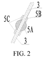
- the anti-snake device 5 comprises a sphere 5A with a smooth surface, the sphere 5A is provided with a through hole 5B, a gap is provided between the through hole 5B and the rigid spacer body 3, to facilitate penetration.
- the upper and lower sides of the sphere 5A are provided with limiting sleeves 5C for fixing the position of the sphere 5A.
- the lower end of the adjusting plate 6 is connected to the span wire 7, and the span wire 7 is fixed onto the ground 8 by using a ground anchor 11.
- the adjusting plate 6 can adjust the length of the span wire 7, thereby changing and adjusting a distance to the ground in the present invention.
- Both the span wire 7 and the adjusting plate 6 are made of special high-strength anti-theft materials.
- the present invention describes an installation manner of the phase-to-ground spacer by using a twin-bundled single-phase wire as an example (for installation manners of a quad-bundled wire, a hexa-bundled wire, an octant-bundled wire and other bundled wires, reference may be made to this embodiment).
- the high-voltage end fitting 1 is connected to the sub-spacer 9 of a wire 10, and the span wire 7 is fixed onto the ground by using the ground anchor 11.
- a phase-to-ground connection manner is used, which can suppress synchronous galloping of two-phase wires and can also suppress asynchronous galloping.
- a land protection pile 12 (a concrete pile) is added, and yellow warning lines are marked on the land protection pile 12, as marks, to prevent damage to the span wire 7 during farming.
- Embodiment 2 is the same as that of Embodiment 1, and Embodiment 2 is different from Embodiment 1 in that, the spacer body in this embodiment is a flexible spacer body 3, which comprises a spacer core and a silicone rubber composite material layer, the spacer core is made of a high-strength force-bearing nylon material, and the silicone rubber composite material layer is located on an outer layer of the spacer core.
- the spacer body in this embodiment is a flexible spacer body 3, which comprises a spacer core and a silicone rubber composite material layer, the spacer core is made of a high-strength force-bearing nylon material, and the silicone rubber composite material layer is located on an outer layer of the spacer core.
- An upper end and a lower end of the flexible spacer body 3 are respectively connected to the connecting fitting and the adjusting plate 6, the connecting fittings is the high-voltage end fitting 1, and the high-voltage end fitting 1 is used to connect the sub-spacer 9.
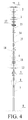
- Embodiment 3 is different from Embodiment 1 in that, as shown in Fig. 4 and Fig. 5 , the spacer body in the present invention is an adjustable spacer (that is, a sectional combined phase-to-ground spacer), and comprises upper and lower spacers: an upper spacer body 3 and a lower spacer body 16, the two spacer bodies are both formed by an inside epoxy resin glass reinforced plastic drawing rod and an outside silicone rubber composite material layer, the insulation umbrella skirt 4 is located on outer sides of the upper spacer body 3 and the lower spacer body 16, and the insulation umbrella skirt 4 and the silicone rubber composite material layer are of a one-piece structure, and are formed integrally.
- the spacer body in the present invention is an adjustable spacer (that is, a sectional combined phase-to-ground spacer), and comprises upper and lower spacers: an upper spacer body 3 and a lower spacer body 16, the two spacer bodies are both formed by an inside epoxy resin glass reinforced plastic drawing rod and an outside silicone rubber composite material layer, the insulation umbrella skirt 4 is located on outer sides
- a middle rod 14 is disposed between the upper spacer body 3 and the lower spacer body 16. Two ends of the middle rod 14 are separately provided with a connecting structure matching a connecting fitting on an end portion of a lower end of the upper spacer body 3 and a connecting structure matching a connecting fitting on an end portion of an upper end of the lower spacer body 16, and a moveable connection manner is used.
- a connecting member used in the connecting structure is a fixing ring 15, and the fixing ring 15 performs a sectional connection of the two spacers.
- middle rods 14 are connected end to end, the middle rods 14 are also connected by using the fixing ring 15, and are moveably connected, and the middle rods 14 are made of the same material as that of the upper spacer body 3 and the lower spacer body 16.
- the uppermost end and the lowest end of the connected middle rods 14 are respectively connected to the end portion of the lower end of the upper spacer body 3 and the end portion of the upper end of the lower spacer body 16.
- An upper end of the upper spacer body 3 is connected to the connecting fitting, the connecting fitting is the high-voltage end fitting 1, the high-voltage end fitting 1 is used to connect the sub-spacer 9, and a lower end of the lower spacer body 16 is connected to the adjusting plate 6.
- the upper end of the upper spacer body 3 is further sleeved with an end-portion accessory: the upper grading ring 2, and the lower end of the upper spacer body 3 is provided with an end-portion accessory: a small upper grading ring 17; the upper end of the lower spacer body 16 is provided with an end-portion accessory: a small lower grading ring 18, and a lower side of the lower spacer body 16 is sleeved with an end-portion accessory: the lower grading ring 13.
- the lower end of the adjusting plate 6 is connected to the span wire 7, and the lower end of the span wire 7 is connected to the ground 8.
- the lower spacer body 16 between the lower grading ring 13 and the adjusting plate 6 is further provided with the anti-snake device 5.
- the structure of the anti-snake device 5 is the same as that in Embodiment 1, and the installation manner is also the same as that in Embodiment 1.
- a spacer formed by a rigid spacer body is referred to as a rigid phase-to-ground spacer; a spacer formed by a flexible spacer body is referred to as a flexible phase-to-ground spacer; and a spacer formed by an adjustable spacer body is referred to as a sectional combined phase-to-ground spacer.
Landscapes
- Suspension Of Electric Lines Or Cables (AREA)
Abstract
Description
- The present invention relates to the field of anti-galloping devices, and specifically to a spacer.
- Overhead transmission lines undertake an important task of power transmission, and their safety is an important factor for ensuring safe operation of power systems. With the continuous expansion of the grid scale and increasing deterioration of the natural environment, in terms of statistical and analytical data of accidents of overhead transmission lines in recent years, the galloping problem has become one of the most important factors that currently threaten the safety of lines. Galloping phenomena of the transmission lines and the harm thereof gradually increase, and galloping may bring various harms, including line flashover and tripping, damage to fittings and insulators, strand breakage and disconnection of wires, while serious galloping may lead to collapse of towers and cause major power grid accidents, and severely threatens the normal operation of the grid.
- Galloping mainly acts on wires by wind, as a result, the distance between adjacent wires may be less than the minimum safe insulation distance at an operating voltage to cause an air insulation breakdown, leading to a power supply accident. Currently, a common practice is to dispose a phase-to-phase spacer between adjacent wires, and connect galloping two-phase wires by using the phase-phase spacer, where the wires restrict each other when galloping, to limit their respective galloping amplitude, and ensure a phase-to-phase insulation distance to prevent line mixing, and the phase-to-phase spacer can play a role of preventing line mixing.
- A phase-to-phase spacer is mainly used to suppress asynchronous galloping of adjacent two-phase wires, so that the two wires gradually move synchronously, so as to reduce the galloping amplitude. Years of operating experience also indicates that the phase-to-phase spacer indeed plays a role in managing galloping.
- However, a phase-to-phase spacer used currently cannot effectively suppress synchronous galloping of two adjacent wires because the phase-to-phase spacer has the following obvious defects:
- First, the phase-to-phase spacer is invalid for synchronous galloping of two adjacent wires; second, when galloping occurs, the phase-to-phase spacer forces synchronization of the two adjacent wires, so that galloping energy of the wires is more concentrated and strengthened, thereby causing greater harm to transmission lines and towers; and for compact lines, due to a triangular arrangement of wires, the phase-to-phase spacer is also subject to pressure and bending force when suppressing tension generated by the galloping, and such pressure and bending force easily cause damage to the phase-to-phase spacer itself and connecting fittings of the wires.
- Moreover, in recent years, there have been lots of fatigue fracture accidents of rigid phase-to-phase spacers or auxiliary fittings thereof, mainly because the rigid phase-to-phase spacers and connecting fittings thereof mainly withstand tensile load, and are designed according to the tolerable tensile load. In the case of iced galloping of the wires, line fittings and insulators are not only subject to the action of the tensile load, but also are bent and twisted under the action of wind, but bending load and torsion load are not within the range of the design of the rigid spacers, and therefore, the rigid spacers are not suitable for withstanding the bending load and the torsion load. When synchronous galloping occurs, a changing impact stress acts on the spacers, and the rigid spacers are easily damaged when subject to such alternating and impact stress. Therefore, in actual operation, the rigid spacers are subject to bending load, torsion load, alternating load, and impact load is the main reason for damage to the rigid spacers and auxiliary fittings thereof.
- An object of the present invention is to provide an anti-galloping phase-to-ground spacer, which can effectively improve suppression effects of synchronous galloping and asynchronous galloping of transmission lines, and significantly improve force conditions of the spacer and a fitting.
- The technical solutions of the present invention are as follows:
- An anti-galloping phase-to-ground spacer comprises: a spacer body, an adjusting plate, and a span wire, wherein an upper end and a lower end of the spacer body are respectively connected to a connecting fitting and the adjusting plate, the spacer body between the connecting fitting and the adjusting plate is sleeved with two end-portion accessories and an insulation umbrella skirt located between the two end-portion accessories, and two ends of the span wire are separately connected to the adjusting plate and the ground.
- The spacer body is a rigid spacer body, the rigid spacer body is formed by an inside epoxy resin glass drawing rod and an outside silicone rubber composite material layer; and the insulation umbrella skirt and the silicone rubber composite material layer are of a one-piece structure.
- The spacer body is a flexible spacer body, and the flexible spacer body comprises a spacer core and a silicone rubber composite material layer, the silicone rubber composite material layer is located on an outer layer of the spacer core, and the spacer core is made of a high-strength force-bearing nylon material.
- The spacer body is an adjustable spacer, the adjustable spacer comprises an upper spacer body, a lower spacer body, and a middle rod connected between the upper spacer body and the lower spacer body. An upper end of the upper spacer body is connected to the connecting fitting, a lower end of the lower spacer body is connected to the adjusting plate, outer circumferences of both the upper spacer body and the lower spacer body are connected to the insulation umbrella skirt, an upper side of the insulation umbrella skirt of the upper spacer body is connected to an end-portion accessory, and a lower side of the insulation umbrella skirt of the lower spacer body is also connected to an end-portion accessory; both a lower end of the upper spacer body and an upper end of the lower spacer body are connected to an end-portion accessory, and the two ends of the span wire are separately connected to the adjusting plate and the ground.
- Both the upper spacer body and the lower spacer body are formed by an inside epoxy resin glass reinforced plastic drawing rod and an outside silicone rubber composite material layer; and the insulation umbrella skirt and the silicone rubber composite material layer are of a one-piece structure.
- The number of the middle rod is one or more.
- The middle rod is movably connected to the upper spacer body and the lower spacer body.
- The middle rod is connected to the upper spacer body and the lower spacer body by a fixing ring.
- The spacer body between the lower end-portion accessory and the adjusting plate is further provided with an anti-snake device.
- The anti-snake device comprises a sphere with a smooth surface, the sphere is provided with a through hole, a gap is provided between the through hole and the rigid spacer body, and upper and lower sides of the sphere are provided with limiting sleeves for fixing the position of the sphere.
- The spacer comprises a sub-spacer whose two ends are connected to wires, wherein the connecting fitting is connected to the sub-spacer.
- The connecting fitting is a high-voltage end fitting.
- The end-portion accessories are grading rings.
- The present invention has the following advantages:
- firstly, the phase-to-ground spacer provided in the present invention can simultaneously suppress synchronous galloping and asynchronous galloping of line wires;
- secondly, the damage problem caused by the fact that the spacer withstands bending load, torsion load, alternating load, and impact load is effectively avoided;
- thirdly, as the phase-to-ground spacer is arranged in a manner of being separately against over the ground, no connection is made between three phases, so that energy strengthening in the case of galloping of three-phase wires can be avoided;
- fourthly, that the phase-to-phase spacer is damaged when withstanding pressure and bending force in the case of a triangular arrangement of the wires is effectively avoided;
- fifthly, the spacer is installed between a line wire and the ground, so that phase-to-phase and phase-to-ground distances can be effectively controlled, phase-to-phase and phase-to-ground short circuits are avoided, security of high-voltage transmission lines is ensured, and an additional insulation distance is not increased;
- sixthly, the insulation umbrella skirt is made of a composite material, which can prevent contamination and icing flashover and improve aging characteristics of an insulator;
- seventhly, the lower end of the spacer body is installed with an anti-snake (rat) device, to prevent an operating accident from being caused by the fact that a snake (rat) or other small animals climb upwards along the insulator;
- eighthly, both the span wire and the adjusting plate on the ground side are made of high-strength anti-theft materials, to prevent criminals from stealing and damaging line equipment.
- The flexible phase-to-ground spacer provided in the present invention has the following advantages:
- firstly, the flexible spacer body in the present invention is made of elastic materials, and generates elastic deformation as a whole when galloping, which can reduce impact load during galloping, and protect the fitting and the insulator;
- secondly, force conditions of the spacer and the auxiliary fitting thereof in use can be significantly improved, thereby effectively avoiding damage to the spacer and the auxiliary fitting thereof caused by bending load, torsion load, and compression load;
- thirdly, the spacer is lightweight, which can reduce tensile damage to the wires after the spacer is installed, and obviously cushions stress concentration of an installation point;
- fourthly, because of its light weight and flexibility, the spacer can be coiled and placed, and is convenient to transport and install.
- A sectional combined phase-to-ground spacer in the present invention, while effectively improving management effects of synchronous galloping and asynchronous galloping of transmission lines, has good insulating effects and an adjustable length, and has the following advantages:
- firstly, the sectional combined phase-to-ground spacer has the advantages of the phase-to-ground spacer, which can simultaneously suppress synchronous galloping and asynchronous galloping of line wires;
- secondly, the sectional combined phase-to-ground spacer has an adjustable length, and can perform a multi-section combination according to requirements of a customer, and a joint between each section can flexibly move under the action of natural wind or wire tension, so as to reduce damage to the spacer caused by wind and ensure a spacing distance between a phase and the ground at the same time;
- thirdly, the spacer is lightweight, convenient to transport, install and maintain;
- fourthly, the spacer has a novel and unique design, is flexible in installation, has a wide range of use, and has good popularization and application values and economic benefits.
-
-
Fig. 1 is a schematic structural diagram ofEmbodiment 1 andEmbodiment 2 of the present invention. -
Fig. 2 is a schematic structural diagram of an anti-snake device according toEmbodiment 1 andEmbodiment 2. -
Fig. 3 is a schematic diagram of installation on a line according toEmbodiment 1 andEmbodiment 2. -
Fig. 4 is a schematic structural diagram ofEmbodiment 3 of the present invention. -
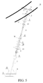
Fig. 5 is a schematic diagram of installation on a line according toEmbodiment 3. - The present invention is applied to a high-voltage transmission line within a range of 110 kV to 1000 kV.
- As shown in
Fig. 1 , the present invention mainly comprises aspacer body 3, anadjusting plate 6, and aspan wire 7..Therigid spacer body 3 is formed by an inside core made of glass fiber reinforced epoxy resin and an outside silicone rubber composite material layer. Theinsulation umbrella skirt 4 and the silicone rubber composite material layer are of a one-piece structure. - An upper end and a lower end of the
rigid spacer body 3 are respectively connected to a high-voltage end fitting 1 (connecting fitting) and the adjustingplate 6, and the high-voltage end fitting 1 is used to connect asub-spacer 9. Therigid spacer body 3 between the high-voltage end fitting 1 and the adjustingplate 6 is sleeved with two end-portion accessories: anupper grading ring 2 and alower grading ring 13, and theinsulation umbrella skirt 4 is located between theupper grading ring 2 and thelower grading ring 13. A lower end of the adjustingplate 6 is connected to thespan wire 7, and a lower end of thespan wire 7 is connected to theground 8. Therigid spacer body 3 between thelower grading ring 13 and the adjustingplate 6 is further provided with ananti-snake device 5. - As shown in
Fig. 2 , theanti-snake device 5 comprises asphere 5A with a smooth surface, thesphere 5A is provided with a throughhole 5B, a gap is provided between the throughhole 5B and therigid spacer body 3, to facilitate penetration. The upper and lower sides of thesphere 5A are provided with limitingsleeves 5C for fixing the position of thesphere 5A. When a snake climbs up to thesphere 5A, thesphere 5A rotates, to make the snake out of balance and fall onto the ground, thereby preventing line discharge and tripping from being caused by the fact that the snake climbs upwards along a spacer core. - The lower end of the adjusting
plate 6 is connected to thespan wire 7, and thespan wire 7 is fixed onto theground 8 by using aground anchor 11. The adjustingplate 6 can adjust the length of thespan wire 7, thereby changing and adjusting a distance to the ground in the present invention. Both thespan wire 7 and the adjustingplate 6 are made of special high-strength anti-theft materials. - As shown in
Fig. 3 , the present invention describes an installation manner of the phase-to-ground spacer by using a twin-bundled single-phase wire as an example (for installation manners of a quad-bundled wire, a hexa-bundled wire, an octant-bundled wire and other bundled wires, reference may be made to this embodiment). The high-voltage end fitting 1 is connected to thesub-spacer 9 of awire 10, and thespan wire 7 is fixed onto the ground by using theground anchor 11. It can be seen that, in the present invention, a phase-to-ground connection manner is used, which can suppress synchronous galloping of two-phase wires and can also suppress asynchronous galloping. When the ground is farmland, a land protection pile 12 (a concrete pile) is added, and yellow warning lines are marked on theland protection pile 12, as marks, to prevent damage to thespan wire 7 during farming. - The schematic structural diagram of
Embodiment 2 is the same as that ofEmbodiment 1, andEmbodiment 2 is different fromEmbodiment 1 in that, the spacer body in this embodiment is aflexible spacer body 3, which comprises a spacer core and a silicone rubber composite material layer, the spacer core is made of a high-strength force-bearing nylon material, and the silicone rubber composite material layer is located on an outer layer of the spacer core. - An upper end and a lower end of the
flexible spacer body 3 are respectively connected to the connecting fitting and the adjustingplate 6, the connecting fittings is the high-voltage end fitting 1, and the high-voltage end fitting 1 is used to connect thesub-spacer 9. -
Embodiment 3 is different fromEmbodiment 1 in that, as shown inFig. 4 andFig. 5 , the spacer body in the present invention is an adjustable spacer (that is, a sectional combined phase-to-ground spacer), and comprises upper and lower spacers: anupper spacer body 3 and alower spacer body 16, the two spacer bodies are both formed by an inside epoxy resin glass reinforced plastic drawing rod and an outside silicone rubber composite material layer, theinsulation umbrella skirt 4 is located on outer sides of theupper spacer body 3 and thelower spacer body 16, and theinsulation umbrella skirt 4 and the silicone rubber composite material layer are of a one-piece structure, and are formed integrally. - A
middle rod 14 is disposed between theupper spacer body 3 and thelower spacer body 16. Two ends of themiddle rod 14 are separately provided with a connecting structure matching a connecting fitting on an end portion of a lower end of theupper spacer body 3 and a connecting structure matching a connecting fitting on an end portion of an upper end of thelower spacer body 16, and a moveable connection manner is used. In this embodiment, a connecting member used in the connecting structure is a fixingring 15, and the fixingring 15 performs a sectional connection of the two spacers. If there are a plurality ofmiddle rods 14, themiddle rods 14 are connected end to end, themiddle rods 14 are also connected by using the fixingring 15, and are moveably connected, and themiddle rods 14 are made of the same material as that of theupper spacer body 3 and thelower spacer body 16. The uppermost end and the lowest end of the connectedmiddle rods 14 are respectively connected to the end portion of the lower end of theupper spacer body 3 and the end portion of the upper end of thelower spacer body 16. - An upper end of the
upper spacer body 3 is connected to the connecting fitting, the connecting fitting is the high-voltage end fitting 1, the high-voltage end fitting 1 is used to connect thesub-spacer 9, and a lower end of thelower spacer body 16 is connected to the adjustingplate 6. - The upper end of the
upper spacer body 3 is further sleeved with an end-portion accessory: theupper grading ring 2, and the lower end of theupper spacer body 3 is provided with an end-portion accessory: a smallupper grading ring 17; the upper end of thelower spacer body 16 is provided with an end-portion accessory: a smalllower grading ring 18, and a lower side of thelower spacer body 16 is sleeved with an end-portion accessory: thelower grading ring 13. The lower end of the adjustingplate 6 is connected to thespan wire 7, and the lower end of thespan wire 7 is connected to theground 8. Thelower spacer body 16 between thelower grading ring 13 and the adjustingplate 6 is further provided with theanti-snake device 5. - The structure of the
anti-snake device 5 is the same as that inEmbodiment 1, and the installation manner is also the same as that inEmbodiment 1. - In the present invention, a spacer formed by a rigid spacer body is referred to as a rigid phase-to-ground spacer; a spacer formed by a flexible spacer body is referred to as a flexible phase-to-ground spacer; and a spacer formed by an adjustable spacer body is referred to as a sectional combined phase-to-ground spacer.
Claims (13)
- An anti-galloping phase-to-ground spacer, comprising: a spacer body, an adjusting plate, and a span wire; an upper end and a lower end of the spacer body are respectively connected to a connecting fitting and the adjusting plate, the spacer body between the connecting fitting and the adjusting plate is sleeved with two end-portion accessories and an insulation umbrella skirt located between the two end-portion accessories, and two ends of the span wire are separately connected to the adjusting plate and the ground.
- The anti-galloping phase-to-ground spacer as in claim 1, wherein the spacer body is a rigid spacer body, the rigid spacer body is formed by an inside epoxy resin glass drawing rod and an outside silicone rubber composite material layer, and the insulation umbrella skirt and the silicone rubber composite material layer are of a one-piece structure.
- The anti-galloping phase-to-ground spacer as in claim 1, wherein the spacer body is a flexible spacer body, the flexible spacer body comprises a spacer core and a silicone rubber composite material layer, the silicone rubber composite material layer is located on an outer layer of the spacer core, and the spacer core is made of a high-strength force-bearing nylon material.
- The anti-galloping phase-to-ground spacer as in claim 1, wherein the spacer body is an adjustable spacer, the adjustable spacer comprises an upper spacer body, a lower spacer body, and a middle rod connected between the upper spacer body and the lower spacer body, an upper end of the upper spacer body is connected to the connecting fitting, a lower end of the lower spacer body is connected to the adjusting plate, outer circumferences of both the upper spacer body and the lower spacer body are connected to the insulation umbrella skirt, an upper side of the insulation umbrella skirt of the upper spacer body is connected to an end-portion accessory, and a lower side of the insulation umbrella skirt of the lower spacer body is also connected to an end-portion accessory; both a lower end of the upper spacer body and an upper end of the lower spacer body are connected to an end-portion accessory, and the two ends of the span wire are separately connected to the adjusting plate and the ground.
- The anti-galloping phase-to-ground spacer as in claim 4, wherein both the upper spacer body and the lower spacer body are formed by an inside epoxy resin glass reinforced plastic drawing rod and an outside silicone rubber composite material layer, and the insulation umbrella skirt and the silicone rubber composite material layer are of a one-piece structure.
- The anti-galloping phase-to-ground spacer as in claim 4 or 5, wherein the number of the middle rod is one or more.
- The anti-galloping phase-to-ground spacer as in claim 4 or 5, wherein the middle rod is moveably connected to the upper spacer body and the lower spacer body.
- The anti-galloping phase-to-ground spacer as in claim 7, wherein the middle rod is connected to the upper spacer body and the lower spacer body by using a fixing ring.
- The anti-galloping phase-to-ground spacer as in any one of claims 1 to 5, wherein the spacer body between the lower end-portion accessory and the adjusting plate is further provided with an anti-snake device.
- The anti-galloping phase-to-ground spacer as in claim 9, wherein the anti-snake device comprises a sphere with a smooth surface, the sphere is provided with a through hole, a gap is provided between the through hole and the spacer body, and upper and lower sides of the sphere are provided with limiting sleeves for fixing the position of the sphere.
- The anti-galloping phase-to-ground spacer as in any one of claims 1 to 5, comprising: a sub-spacer whose two ends are connected to wires, wherein the connecting fitting is connected to the sub-spacer.
- The anti-galloping phase-to-ground spacer as in any one of claims 1 to 5, wherein the connecting fitting is a high-voltage end fitting.
- The anti-galloping phase-to-ground spacer as in any one of claims 1 to 5, wherein the end-portion accessories are grading rings.
Applications Claiming Priority (4)
| Application Number | Priority Date | Filing Date | Title |
|---|---|---|---|
| CN201310310227.1A CN103457220B (en) | 2013-07-23 | 2013-07-23 | A kind of anti-gallop flexible composite phase-to-ground spacer |
| CN201310310480.7A CN103441462B (en) | 2013-07-23 | 2013-07-23 | Segmental combined type galloping-prevention composite phase-earth spacing rod |
| CN201310310300.5A CN103414135B (en) | 2013-07-23 | 2013-07-23 | A kind of anti-with waving rigidity phase conductor spacer |
| PCT/CN2013/088050 WO2015010403A1 (en) | 2013-07-23 | 2013-11-28 | Anti-galloping phase-to-ground spacer |
Publications (3)
| Publication Number | Publication Date |
|---|---|
| EP3026768A1 true EP3026768A1 (en) | 2016-06-01 |
| EP3026768A4 EP3026768A4 (en) | 2017-08-09 |
| EP3026768B1 EP3026768B1 (en) | 2020-07-29 |
Family
ID=52392657
Family Applications (1)
| Application Number | Title | Priority Date | Filing Date |
|---|---|---|---|
| EP13889866.3A Active EP3026768B1 (en) | 2013-07-23 | 2013-11-28 | Anti-galloping phase-to-ground spacer |
Country Status (2)
| Country | Link |
|---|---|
| EP (1) | EP3026768B1 (en) |
| WO (1) | WO2015010403A1 (en) |
Cited By (2)
| Publication number | Priority date | Publication date | Assignee | Title |
|---|---|---|---|---|
| CN106099813A (en) * | 2016-06-24 | 2016-11-09 | 国网河南省电力公司电力科学研究院 | A kind of extra-high voltage is arranged vertically power transmission line comprehensive anti-dance approach |
| CN106129944A (en) * | 2016-06-24 | 2016-11-16 | 国网河南省电力公司电力科学研究院 | A kind of extra-high voltage horizontally disposed transmission line of electricity anti-dance approach |
Family Cites Families (12)
| Publication number | Priority date | Publication date | Assignee | Title |
|---|---|---|---|---|
| FR2643757B1 (en) * | 1989-02-24 | 1991-06-07 | Cahors App Elec | METHOD AND TOOL FOR LAYING A CONDUCTOR SPACER FROM AN OVERHEAD ELECTRICAL LINE FROM THE GROUND, AND A SPACER RELATING THERETO |
| US5700980A (en) * | 1995-05-18 | 1997-12-23 | Conductron Corporation | Aerial cable spacer |
| JP2000308246A (en) * | 1999-02-15 | 2000-11-02 | Furukawa Electric Co Ltd:The | Galloping prevention device |
| JP2003224924A (en) * | 2002-01-29 | 2003-08-08 | Kansai Electric Power Co Inc:The | Transmission line phase spacer |
| CN101931192A (en) * | 2009-06-23 | 2010-12-29 | 江苏省电力公司仪征市供电公司 | Insulated cable protection device |
| KR101103553B1 (en) * | 2011-03-07 | 2012-01-06 | 대원전기 주식회사 | Uninterrupted Bypass Method for Distribution Lines Using Insulating Guiders for Space Maintenance |
| CN202262345U (en) * | 2011-09-28 | 2012-06-06 | 吕海波 | Roller for mouse-snake preventer |
| CN202772532U (en) * | 2012-07-11 | 2013-03-06 | 广州市迈克林电力有限公司 | Ground/conducting wire energy-releasing bar and ground/conducting wire spacing bar |
| CN203339620U (en) * | 2013-07-23 | 2013-12-11 | 国家电网公司 | Anti-galloping flexible composite phase-ground spacer rod |
| CN203522087U (en) * | 2013-07-23 | 2014-04-02 | 国家电网公司 | Anti-gallop rigid phase-ground spacer |
| CN103414135B (en) * | 2013-07-23 | 2016-06-01 | 国家电网公司 | A kind of anti-with waving rigidity phase conductor spacer |
| CN203434573U (en) * | 2013-07-23 | 2014-02-12 | 国家电网公司 | Node combined type anti-waving composite phase spacer rod |
-
2013
- 2013-11-28 EP EP13889866.3A patent/EP3026768B1/en active Active
- 2013-11-28 WO PCT/CN2013/088050 patent/WO2015010403A1/en not_active Ceased
Non-Patent Citations (1)
| Title |
|---|
| See references of WO2015010403A1 * |
Cited By (4)
| Publication number | Priority date | Publication date | Assignee | Title |
|---|---|---|---|---|
| CN106099813A (en) * | 2016-06-24 | 2016-11-09 | 国网河南省电力公司电力科学研究院 | A kind of extra-high voltage is arranged vertically power transmission line comprehensive anti-dance approach |
| CN106129944A (en) * | 2016-06-24 | 2016-11-16 | 国网河南省电力公司电力科学研究院 | A kind of extra-high voltage horizontally disposed transmission line of electricity anti-dance approach |
| CN106099813B (en) * | 2016-06-24 | 2017-09-08 | 国网河南省电力公司电力科学研究院 | A kind of extra-high voltage is arranged vertically power transmission line comprehensive anti-dance approach |
| CN106129944B (en) * | 2016-06-24 | 2017-11-28 | 国网河南省电力公司电力科学研究院 | A kind of horizontally disposed transmission line of electricity anti-dance approach of extra-high voltage |
Also Published As
| Publication number | Publication date |
|---|---|
| WO2015010403A1 (en) | 2015-01-29 |
| EP3026768A4 (en) | 2017-08-09 |
| EP3026768B1 (en) | 2020-07-29 |
Similar Documents
| Publication | Publication Date | Title |
|---|---|---|
| CN103441462B (en) | Segmental combined type galloping-prevention composite phase-earth spacing rod | |
| ES2967100T3 (en) | Overhead electric power distribution line | |
| KR101707758B1 (en) | Composite tower for power transmission lines of power grid and composite cross arm structure thereof | |
| US9633766B2 (en) | Energy efficient conductors with reduced thermal knee points and the method of manufacture thereof | |
| CN107093881B (en) | A kind of damping unit for being used to inhibit electric transmission line isolator windage yaw | |
| US10886036B2 (en) | Energy efficient conductors with reduced thermal knee points and the method of manufacture thereof | |
| EP3026768B1 (en) | Anti-galloping phase-to-ground spacer | |
| CN103414135B (en) | A kind of anti-with waving rigidity phase conductor spacer | |
| CN203339620U (en) | Anti-galloping flexible composite phase-ground spacer rod | |
| CN203536908U (en) | Sectional combined wind deflection composite insulation cable | |
| US3291899A (en) | Electric insulators in the form of framed structures incorporating rods of resin bonded fibre | |
| CN203434573U (en) | Node combined type anti-waving composite phase spacer rod | |
| CN104895390B (en) | A kind of tangent tower | |
| Florea et al. | Upgrading the Romanian 400 kV lines with 2 and 3 subconductors per phase to reduce the risk of galloping occurance and the galloping amplitudes by the installation of torsional dampers and detuners, live-line procedures | |
| CN203522087U (en) | Anti-gallop rigid phase-ground spacer | |
| CN103457220B (en) | A kind of anti-gallop flexible composite phase-to-ground spacer | |
| CN214273121U (en) | cable tower | |
| CN203536907U (en) | High voltage power transmission line wind deviation-resistant flexible insulation inhaul cable | |
| CN103606873A (en) | Sectioned combination-type wind-deflection-preventing composite insulating inhaul cable and installation method | |
| DE102016223791A1 (en) | Bird protection and attachment point for an overhead line | |
| CN207069519U (en) | Overhead transmission line protection device and system for windage yaw | |
| EP3857660B1 (en) | Lightning management module for structural cable and corresponding method and structural cable | |
| CN100483879C (en) | Transmission-line damping lightning arrester against winding shock | |
| CN104104047B (en) | Supporting type wind deflection prevention device | |
| Florea et al. | A performant antigalloping device for the 400 kV O/H lines with 3 subconductors was designed tested manufactured and installed in Romania in 2015. Live-line procedures available |
Legal Events
| Date | Code | Title | Description |
|---|---|---|---|
| PUAI | Public reference made under article 153(3) epc to a published international application that has entered the european phase |
Free format text: ORIGINAL CODE: 0009012 |
|
| 17P | Request for examination filed |
Effective date: 20150615 |
|
| AK | Designated contracting states |
Kind code of ref document: A1 Designated state(s): AL AT BE BG CH CY CZ DE DK EE ES FI FR GB GR HR HU IE IS IT LI LT LU LV MC MK MT NL NO PL PT RO RS SE SI SK SM TR |
|
| AX | Request for extension of the european patent |
Extension state: BA ME |
|
| DAX | Request for extension of the european patent (deleted) | ||
| A4 | Supplementary search report drawn up and despatched |
Effective date: 20170707 |
|
| RIC1 | Information provided on ipc code assigned before grant |
Ipc: H02G 7/14 20060101ALI20170704BHEP Ipc: H02G 7/12 20060101AFI20170704BHEP |
|
| STAA | Information on the status of an ep patent application or granted ep patent |
Free format text: STATUS: EXAMINATION IS IN PROGRESS |
|
| 17Q | First examination report despatched |
Effective date: 20180608 |
|
| GRAP | Despatch of communication of intention to grant a patent |
Free format text: ORIGINAL CODE: EPIDOSNIGR1 |
|
| STAA | Information on the status of an ep patent application or granted ep patent |
Free format text: STATUS: GRANT OF PATENT IS INTENDED |
|
| INTG | Intention to grant announced |
Effective date: 20200218 |
|
| RAP1 | Party data changed (applicant data changed or rights of an application transferred) |
Owner name: STATE GRID CORPORATION OF CHINA Owner name: STATE GRID HENAN ELECTRIC POWER CORPORATION ELECTRIC POWER SCIENCE RESEARCH INSTITUTE |
|
| GRAS | Grant fee paid |
Free format text: ORIGINAL CODE: EPIDOSNIGR3 |
|
| GRAA | (expected) grant |
Free format text: ORIGINAL CODE: 0009210 |
|
| STAA | Information on the status of an ep patent application or granted ep patent |
Free format text: STATUS: THE PATENT HAS BEEN GRANTED |
|
| AK | Designated contracting states |
Kind code of ref document: B1 Designated state(s): AL AT BE BG CH CY CZ DE DK EE ES FI FR GB GR HR HU IE IS IT LI LT LU LV MC MK MT NL NO PL PT RO RS SE SI SK SM TR |
|
| REG | Reference to a national code |
Ref country code: CH Ref legal event code: EP |
|
| REG | Reference to a national code |
Ref country code: AT Ref legal event code: REF Ref document number: 1296913 Country of ref document: AT Kind code of ref document: T Effective date: 20200815 |
|
| REG | Reference to a national code |
Ref country code: IE Ref legal event code: FG4D |
|
| REG | Reference to a national code |
Ref country code: DE Ref legal event code: R096 Ref document number: 602013071216 Country of ref document: DE |
|
| REG | Reference to a national code |
Ref country code: LT Ref legal event code: MG4D |
|
| REG | Reference to a national code |
Ref country code: NL Ref legal event code: MP Effective date: 20200729 |
|
| REG | Reference to a national code |
Ref country code: AT Ref legal event code: MK05 Ref document number: 1296913 Country of ref document: AT Kind code of ref document: T Effective date: 20200729 |
|
| PG25 | Lapsed in a contracting state [announced via postgrant information from national office to epo] |
Ref country code: GR Free format text: LAPSE BECAUSE OF FAILURE TO SUBMIT A TRANSLATION OF THE DESCRIPTION OR TO PAY THE FEE WITHIN THE PRESCRIBED TIME-LIMIT Effective date: 20201030 Ref country code: FI Free format text: LAPSE BECAUSE OF FAILURE TO SUBMIT A TRANSLATION OF THE DESCRIPTION OR TO PAY THE FEE WITHIN THE PRESCRIBED TIME-LIMIT Effective date: 20200729 Ref country code: PT Free format text: LAPSE BECAUSE OF FAILURE TO SUBMIT A TRANSLATION OF THE DESCRIPTION OR TO PAY THE FEE WITHIN THE PRESCRIBED TIME-LIMIT Effective date: 20201130 Ref country code: AT Free format text: LAPSE BECAUSE OF FAILURE TO SUBMIT A TRANSLATION OF THE DESCRIPTION OR TO PAY THE FEE WITHIN THE PRESCRIBED TIME-LIMIT Effective date: 20200729 Ref country code: NO Free format text: LAPSE BECAUSE OF FAILURE TO SUBMIT A TRANSLATION OF THE DESCRIPTION OR TO PAY THE FEE WITHIN THE PRESCRIBED TIME-LIMIT Effective date: 20201029 Ref country code: ES Free format text: LAPSE BECAUSE OF FAILURE TO SUBMIT A TRANSLATION OF THE DESCRIPTION OR TO PAY THE FEE WITHIN THE PRESCRIBED TIME-LIMIT Effective date: 20200729 Ref country code: BG Free format text: LAPSE BECAUSE OF FAILURE TO SUBMIT A TRANSLATION OF THE DESCRIPTION OR TO PAY THE FEE WITHIN THE PRESCRIBED TIME-LIMIT Effective date: 20201029 Ref country code: SE Free format text: LAPSE BECAUSE OF FAILURE TO SUBMIT A TRANSLATION OF THE DESCRIPTION OR TO PAY THE FEE WITHIN THE PRESCRIBED TIME-LIMIT Effective date: 20200729 Ref country code: HR Free format text: LAPSE BECAUSE OF FAILURE TO SUBMIT A TRANSLATION OF THE DESCRIPTION OR TO PAY THE FEE WITHIN THE PRESCRIBED TIME-LIMIT Effective date: 20200729 Ref country code: LT Free format text: LAPSE BECAUSE OF FAILURE TO SUBMIT A TRANSLATION OF THE DESCRIPTION OR TO PAY THE FEE WITHIN THE PRESCRIBED TIME-LIMIT Effective date: 20200729 |
|
| PG25 | Lapsed in a contracting state [announced via postgrant information from national office to epo] |
Ref country code: PL Free format text: LAPSE BECAUSE OF FAILURE TO SUBMIT A TRANSLATION OF THE DESCRIPTION OR TO PAY THE FEE WITHIN THE PRESCRIBED TIME-LIMIT Effective date: 20200729 Ref country code: RS Free format text: LAPSE BECAUSE OF FAILURE TO SUBMIT A TRANSLATION OF THE DESCRIPTION OR TO PAY THE FEE WITHIN THE PRESCRIBED TIME-LIMIT Effective date: 20200729 Ref country code: LV Free format text: LAPSE BECAUSE OF FAILURE TO SUBMIT A TRANSLATION OF THE DESCRIPTION OR TO PAY THE FEE WITHIN THE PRESCRIBED TIME-LIMIT Effective date: 20200729 Ref country code: IS Free format text: LAPSE BECAUSE OF FAILURE TO SUBMIT A TRANSLATION OF THE DESCRIPTION OR TO PAY THE FEE WITHIN THE PRESCRIBED TIME-LIMIT Effective date: 20201129 |
|
| PG25 | Lapsed in a contracting state [announced via postgrant information from national office to epo] |
Ref country code: NL Free format text: LAPSE BECAUSE OF FAILURE TO SUBMIT A TRANSLATION OF THE DESCRIPTION OR TO PAY THE FEE WITHIN THE PRESCRIBED TIME-LIMIT Effective date: 20200729 |
|
| PG25 | Lapsed in a contracting state [announced via postgrant information from national office to epo] |
Ref country code: IT Free format text: LAPSE BECAUSE OF FAILURE TO SUBMIT A TRANSLATION OF THE DESCRIPTION OR TO PAY THE FEE WITHIN THE PRESCRIBED TIME-LIMIT Effective date: 20200729 Ref country code: CZ Free format text: LAPSE BECAUSE OF FAILURE TO SUBMIT A TRANSLATION OF THE DESCRIPTION OR TO PAY THE FEE WITHIN THE PRESCRIBED TIME-LIMIT Effective date: 20200729 Ref country code: EE Free format text: LAPSE BECAUSE OF FAILURE TO SUBMIT A TRANSLATION OF THE DESCRIPTION OR TO PAY THE FEE WITHIN THE PRESCRIBED TIME-LIMIT Effective date: 20200729 Ref country code: DK Free format text: LAPSE BECAUSE OF FAILURE TO SUBMIT A TRANSLATION OF THE DESCRIPTION OR TO PAY THE FEE WITHIN THE PRESCRIBED TIME-LIMIT Effective date: 20200729 Ref country code: RO Free format text: LAPSE BECAUSE OF FAILURE TO SUBMIT A TRANSLATION OF THE DESCRIPTION OR TO PAY THE FEE WITHIN THE PRESCRIBED TIME-LIMIT Effective date: 20200729 Ref country code: SM Free format text: LAPSE BECAUSE OF FAILURE TO SUBMIT A TRANSLATION OF THE DESCRIPTION OR TO PAY THE FEE WITHIN THE PRESCRIBED TIME-LIMIT Effective date: 20200729 |
|
| REG | Reference to a national code |
Ref country code: DE Ref legal event code: R097 Ref document number: 602013071216 Country of ref document: DE |
|
| PG25 | Lapsed in a contracting state [announced via postgrant information from national office to epo] |
Ref country code: AL Free format text: LAPSE BECAUSE OF FAILURE TO SUBMIT A TRANSLATION OF THE DESCRIPTION OR TO PAY THE FEE WITHIN THE PRESCRIBED TIME-LIMIT Effective date: 20200729 |
|
| REG | Reference to a national code |
Ref country code: DE Ref legal event code: R119 Ref document number: 602013071216 Country of ref document: DE |
|
| PLBE | No opposition filed within time limit |
Free format text: ORIGINAL CODE: 0009261 |
|
| STAA | Information on the status of an ep patent application or granted ep patent |
Free format text: STATUS: NO OPPOSITION FILED WITHIN TIME LIMIT |
|
| PG25 | Lapsed in a contracting state [announced via postgrant information from national office to epo] |
Ref country code: SK Free format text: LAPSE BECAUSE OF FAILURE TO SUBMIT A TRANSLATION OF THE DESCRIPTION OR TO PAY THE FEE WITHIN THE PRESCRIBED TIME-LIMIT Effective date: 20200729 Ref country code: MC Free format text: LAPSE BECAUSE OF FAILURE TO SUBMIT A TRANSLATION OF THE DESCRIPTION OR TO PAY THE FEE WITHIN THE PRESCRIBED TIME-LIMIT Effective date: 20200729 |
|
| REG | Reference to a national code |
Ref country code: CH Ref legal event code: PL |
|
| 26N | No opposition filed |
Effective date: 20210430 |
|
| GBPC | Gb: european patent ceased through non-payment of renewal fee |
Effective date: 20201128 |
|
| PG25 | Lapsed in a contracting state [announced via postgrant information from national office to epo] |
Ref country code: LU Free format text: LAPSE BECAUSE OF NON-PAYMENT OF DUE FEES Effective date: 20201128 |
|
| REG | Reference to a national code |
Ref country code: BE Ref legal event code: MM Effective date: 20201130 |
|
| PG25 | Lapsed in a contracting state [announced via postgrant information from national office to epo] |
Ref country code: CH Free format text: LAPSE BECAUSE OF NON-PAYMENT OF DUE FEES Effective date: 20201130 Ref country code: SI Free format text: LAPSE BECAUSE OF FAILURE TO SUBMIT A TRANSLATION OF THE DESCRIPTION OR TO PAY THE FEE WITHIN THE PRESCRIBED TIME-LIMIT Effective date: 20200729 Ref country code: LI Free format text: LAPSE BECAUSE OF NON-PAYMENT OF DUE FEES Effective date: 20201130 |
|
| PG25 | Lapsed in a contracting state [announced via postgrant information from national office to epo] |
Ref country code: IE Free format text: LAPSE BECAUSE OF NON-PAYMENT OF DUE FEES Effective date: 20201128 Ref country code: FR Free format text: LAPSE BECAUSE OF NON-PAYMENT OF DUE FEES Effective date: 20201130 |
|
| PG25 | Lapsed in a contracting state [announced via postgrant information from national office to epo] |
Ref country code: GB Free format text: LAPSE BECAUSE OF NON-PAYMENT OF DUE FEES Effective date: 20201128 Ref country code: DE Free format text: LAPSE BECAUSE OF NON-PAYMENT OF DUE FEES Effective date: 20210601 |
|
| PG25 | Lapsed in a contracting state [announced via postgrant information from national office to epo] |
Ref country code: IS Free format text: LAPSE BECAUSE OF FAILURE TO SUBMIT A TRANSLATION OF THE DESCRIPTION OR TO PAY THE FEE WITHIN THE PRESCRIBED TIME-LIMIT Effective date: 20201129 Ref country code: TR Free format text: LAPSE BECAUSE OF FAILURE TO SUBMIT A TRANSLATION OF THE DESCRIPTION OR TO PAY THE FEE WITHIN THE PRESCRIBED TIME-LIMIT Effective date: 20200729 Ref country code: MT Free format text: LAPSE BECAUSE OF FAILURE TO SUBMIT A TRANSLATION OF THE DESCRIPTION OR TO PAY THE FEE WITHIN THE PRESCRIBED TIME-LIMIT Effective date: 20200729 Ref country code: CY Free format text: LAPSE BECAUSE OF FAILURE TO SUBMIT A TRANSLATION OF THE DESCRIPTION OR TO PAY THE FEE WITHIN THE PRESCRIBED TIME-LIMIT Effective date: 20200729 |
|
| PG25 | Lapsed in a contracting state [announced via postgrant information from national office to epo] |
Ref country code: MK Free format text: LAPSE BECAUSE OF FAILURE TO SUBMIT A TRANSLATION OF THE DESCRIPTION OR TO PAY THE FEE WITHIN THE PRESCRIBED TIME-LIMIT Effective date: 20200729 |
|
| PG25 | Lapsed in a contracting state [announced via postgrant information from national office to epo] |
Ref country code: BE Free format text: LAPSE BECAUSE OF NON-PAYMENT OF DUE FEES Effective date: 20201130 |