EP3026763A1 - Electric apparatus with safety connector for preventing electric shock - Google Patents
Electric apparatus with safety connector for preventing electric shock Download PDFInfo
- Publication number
- EP3026763A1 EP3026763A1 EP15196194.3A EP15196194A EP3026763A1 EP 3026763 A1 EP3026763 A1 EP 3026763A1 EP 15196194 A EP15196194 A EP 15196194A EP 3026763 A1 EP3026763 A1 EP 3026763A1
- Authority
- EP
- European Patent Office
- Prior art keywords
- cover
- safety connector
- electric
- terminals
- electric circuit
- Prior art date
- Legal status (The legal status is an assumption and is not a legal conclusion. Google has not performed a legal analysis and makes no representation as to the accuracy of the status listed.)
- Granted
Links
Images




Classifications
-
- H—ELECTRICITY
- H01—ELECTRIC ELEMENTS
- H01R—ELECTRICALLY-CONDUCTIVE CONNECTIONS; STRUCTURAL ASSOCIATIONS OF A PLURALITY OF MUTUALLY-INSULATED ELECTRICAL CONNECTING ELEMENTS; COUPLING DEVICES; CURRENT COLLECTORS
- H01R13/00—Details of coupling devices of the kinds covered by groups H01R12/70 or H01R24/00 - H01R33/00
- H01R13/44—Means for preventing access to live contacts
- H01R13/447—Shutter or cover plate
-
- H—ELECTRICITY
- H01—ELECTRIC ELEMENTS
- H01R—ELECTRICALLY-CONDUCTIVE CONNECTIONS; STRUCTURAL ASSOCIATIONS OF A PLURALITY OF MUTUALLY-INSULATED ELECTRICAL CONNECTING ELEMENTS; COUPLING DEVICES; CURRENT COLLECTORS
- H01R31/00—Coupling parts supported only by co-operation with counterpart
- H01R31/08—Short-circuiting members for bridging contacts in a counterpart
-
- H—ELECTRICITY
- H01—ELECTRIC ELEMENTS
- H01H—ELECTRIC SWITCHES; RELAYS; SELECTORS; EMERGENCY PROTECTIVE DEVICES
- H01H27/00—Switches operated by a removable member, e.g. key, plug or plate; Switches operated by setting members according to a single predetermined combination out of several possible settings
- H01H27/06—Key inserted and then turned to effect operation of the switch
- H01H27/08—Key inserted and then turned to effect operation of the switch wherein the key cannot be removed until the switch is returned to its original position
-
- H—ELECTRICITY
- H01—ELECTRIC ELEMENTS
- H01R—ELECTRICALLY-CONDUCTIVE CONNECTIONS; STRUCTURAL ASSOCIATIONS OF A PLURALITY OF MUTUALLY-INSULATED ELECTRICAL CONNECTING ELEMENTS; COUPLING DEVICES; CURRENT COLLECTORS
- H01R13/00—Details of coupling devices of the kinds covered by groups H01R12/70 or H01R24/00 - H01R33/00
- H01R13/46—Bases; Cases
-
- H—ELECTRICITY
- H01—ELECTRIC ELEMENTS
- H01R—ELECTRICALLY-CONDUCTIVE CONNECTIONS; STRUCTURAL ASSOCIATIONS OF A PLURALITY OF MUTUALLY-INSULATED ELECTRICAL CONNECTING ELEMENTS; COUPLING DEVICES; CURRENT COLLECTORS
- H01R13/00—Details of coupling devices of the kinds covered by groups H01R12/70 or H01R24/00 - H01R33/00
- H01R13/66—Structural association with built-in electrical component
- H01R13/70—Structural association with built-in electrical component with built-in switch
- H01R13/703—Structural association with built-in electrical component with built-in switch operated by engagement or disengagement of coupling parts, e.g. dual-continuity coupling part
- H01R13/7031—Shorting, shunting or bussing of different terminals interrupted or effected on engagement of coupling part, e.g. for ESD protection, line continuity
-
- H—ELECTRICITY
- H01—ELECTRIC ELEMENTS
- H01R—ELECTRICALLY-CONDUCTIVE CONNECTIONS; STRUCTURAL ASSOCIATIONS OF A PLURALITY OF MUTUALLY-INSULATED ELECTRICAL CONNECTING ELEMENTS; COUPLING DEVICES; CURRENT COLLECTORS
- H01R13/00—Details of coupling devices of the kinds covered by groups H01R12/70 or H01R24/00 - H01R33/00
- H01R13/62—Means for facilitating engagement or disengagement of coupling parts or for holding them in engagement
- H01R13/629—Additional means for facilitating engagement or disengagement of coupling parts, e.g. aligning or guiding means, levers, gas pressure electrical locking indicators, manufacturing tolerances
- H01R13/633—Additional means for facilitating engagement or disengagement of coupling parts, e.g. aligning or guiding means, levers, gas pressure electrical locking indicators, manufacturing tolerances for disengagement only
- H01R13/635—Additional means for facilitating engagement or disengagement of coupling parts, e.g. aligning or guiding means, levers, gas pressure electrical locking indicators, manufacturing tolerances for disengagement only by mechanical pressure, e.g. spring force
-
- H—ELECTRICITY
- H01—ELECTRIC ELEMENTS
- H01R—ELECTRICALLY-CONDUCTIVE CONNECTIONS; STRUCTURAL ASSOCIATIONS OF A PLURALITY OF MUTUALLY-INSULATED ELECTRICAL CONNECTING ELEMENTS; COUPLING DEVICES; CURRENT COLLECTORS
- H01R2201/00—Connectors or connections adapted for particular applications
- H01R2201/26—Connectors or connections adapted for particular applications for vehicles
Definitions
- This invention relates to an electric apparatus with safety connector for preventing electric shock, in particular in the automotive sector.
- this time interval must be sufficient to allow the capacitors of the electric circuit to discharge so as to prevent any risk of electric shock to the maintainer.
- covers that perform the function of both mechanical coverage of live parts and that of opening the electric circuit.
- a first outer cover when removed, opens the electric circuit and allows access to a second cover, which can have the mere function of mechanical protection.
- the time required to remove the second cover ensures the aforementioned discharge of the capacitors.
- reference number 4 globally indicates an overall schematic view of an electric apparatus according to this invention.
- the electric apparatus 4 comprises an electric circuit 8 comprising at least one pair of terminals 12,14 electrically separate from each other so as to keep the electric circuit open.
- the terminals 12,14 are normally facing and electrically disconnected from each other, so as to have an open electric circuit.
- the electric apparatus 4 also comprises a cover 16 that covers said electric circuit 8 so as to prevent access when the cover 16 is disposed in assembly configuration to cover the electric circuit 8.
- the cover 16 has the function of physically preventing access to parts of the live electric circuit 8 so as to prevent the risk of an operator receiving an electric shock.
- the cover 16 is mechanically fixed in place by a plurality of attachment means 20.
- the attachment means 20 may comprise screws and bolts having heads 22 that rest on an outer wall 24 of the cover, opposite to the electric circuit 8.
- the electric apparatus 4 comprises a safety connector 28 associated to the cover 16 and provided with an electric conductor element 32; the safety connector 28 passes through the cover 16 so as to intercept and short-circuit the terminals 12,14.
- the safety connector 28 is provided with a projection 36 that supports the electric conductor element 32 and is movable from a closed configuration, in which it short-circuits the terminals 12,14 to an open position in which it does not short-circuit the terminals 12, 14 (thus leaving the circuit electrically open).
- the safety connector 28 can be at least partially removed from the cover 16 so as not to short-circuit the terminals 12,14, in the open position or configuration.
- the projection 36 passes through an engagement hole 38 of the cover 16 so as to intercept the terminals 12,14 of the electrical circuit 8.
- the safety connector 28 is provided with a cover element 40 that, in said closed configuration, at least partially overlaps at least one of said attachment means 20 of the cover 16, preventing its removal.
- the cover element 40 is superimposed at least partially on at least one of the attachment means 20, for example overlying a head 22 of an attachment means 20 so as to prevent the operator from reaching the head with a tool such as a screwdriver or a spanner, and/or to prevent, in any case, the operator from removing the attachment means 20 and thus the cover 16 itself.
- a tool such as a screwdriver or a spanner
- a single attachment means 20 is always shown intercepted and/or surmounted by said cover element 40; for the purposes of this invention, it is also possible to provide that two or more attachment means 20 can be surmounted, intercepted and therefore in position by the cover element 40 as long as the safety connector 28 is disposed in the closed position.
- the safety of the device is increased since it extends the time the operator needs to disassemble all the attachment means after having rotated/moved the safety connector 28 and thus after opening the electric circuit. In other words it further increases the discharge time of the capacitors of the electric circuit 8, before the operator can come in contact with it.
- the cover element 40 is superimposed on the cover 16, on the side opposite the electric circuit 8, i.e., on the side of said outer wall 24 of the cover itself.
- the cover element 40 is configured as a gripping element so as to allow both the gripping/movement of the safety connector 28 and the blocking of the removal at least one of the attachment means 20 of the cover 16.
- the safety connector 28 is axially inserted, through the cover 16 by means of a shape coupling; according to an embodiment said shape coupling is a prismatic coupling which enables an axial insertion of the safety connector 28 within the cover 16 parallel to an axial direction of insertion Y-Y.
- the safety connector 28 can be at least partially removed from the cover 16 so as not to short-circuit the terminals 12,14, in the open position or configuration, by means of detaching at least partially the safety connector from the cover 16. In this way, in fact, the electric conductor element 32 is physically detached from the terminals 12,14.
- the safety connector 28 is fixed to the relative lid 16 by means of screws 42; preferably such screws 42 are captive screws.
- the safety connector 28 is rotatably attached to the cover 16 with respect to an axis of rotation X-X, so as to rotate from the open position, in which the projection 36 is offset with respect to the terminals 12, 14 so as not to short-circuit them, and the cover element 40 is offset with respect to at least one of the attachment means 20 of the lid 16, to the closed position in which the projection 36 short-circuits the terminals 12,14 and the cover element 40 overlaps at least one of the attachment means 20.
- the safety connector 28 can be rotated within the cover 16, without being removed from the cover so as not to short-circuit the terminals 12,14, in the open position or configuration.
- connection means 44 are joined together by connection means 44, so as to be mutually detachable.
- connection means 44 may comprise teeth, fins or tabs that create a mutual shape connection, preferably of the snap type.
- the projection 36 has the function of short-circuiting the terminals 12,14: for example, the projection 36 comprises a spring 48 in conductive material fitted with a pair of projecting flexible tabs 52 that, in the closed configuration, short-circuit said terminals 12,14 and that, in the open configuration, are offset with respect to the terminals 12,14 so as to leave the electric circuit 8 open.
- the projection 36 is fitted with a pair of conductor plates 56 diametrically opposite and electrically connected to each other, so that, in the closed configuration, the conductor plates 56 are facing and electrically connected to the terminals 12,14 and, in the open configuration, said conductor plates 56 are offset with respect to the terminals 12,14.
- the projection 36 is provided with at least one retention tooth 60, counter-shaped to a corresponding seat 62 on the cover 16 made at the engagement hole 38, in which the retention tooth 60 allows the insertion of the projection 36 through the seat 62 when the safety connector 28 is in the open position, and abuts against a stop wall 64 of the cover 16 so as to prevent the removal of the safety connector 28 from the seat 62 in the closed configuration.
- the projection 36 is provided with two retention teeth 60 counter-shaped to respective seats 62 on the cover 16 formed in correspondence of the engagement hole 38.
- the retention teeth 60 can be different from each other, each associated to a corresponding counter-shaped seat 62, so as to ensure a proper assembly of the safety connector 28 on the cover 16.
- stop wall 64 is facing the electric circuit 8 and opposite to the outer wall 24 of the cover 16.
- a gasket 68 associated with the safety connector 28 is placed next to said engagement hole 38, so as to seal closed the connection between the safety connector 28 and the cover 16.
- the gasket 68 is placed and/or shaped so as to be influenced in compression when the retention tooth 60 crosses the seat 62 and stops in abutment against the stop wall 64 of the cover 16.
- the portion of cover 16 that delimits the engagement hole 38 has a truncated cone shape that narrows towards the electric circuit 8.
- This truncated cone configuration ensures a uniform compression of the gasket 68 and improves the overall hermetic seal of the coupling of the safety connector 28.
- the terminals 12,14 of the electric circuit 8 are, for example, supported by base plates 70 at least partially counter-shaped to the projection 36 of the safety connector 28, so as to support the mechanical contact between the terminals 12,14 and the projection 36 in the closed configuration of the safety connector 28.
- the safety connector 28 is fitted with a return spring 72 that influences the safety connector to move into the open configuration.
- the cover 16 is provided with a limit switch in opening 76, which projects from the cover 16 from the opposite side to the electric circuit 8 in order to achieve the maximum displacement when opening the safety connector 28 in order to allow free access and the removal of the attachment means 20 influenced by the cover element 40 in the closed configuration.
- the cover 16 is provided with a limit switch in closing 80, which projects from the cover 16 from the opposite side to the electric circuit 8 in order to achieve the maximum displacement when closing the safety connector 28 in order to prevent free access and the removal of the attachment means 20 influenced by the cover element 40 in the closed configuration.
- a limit switch in closing 80 which projects from the cover 16 from the opposite side to the electric circuit 8 in order to achieve the maximum displacement when closing the safety connector 28 in order to prevent free access and the removal of the attachment means 20 influenced by the cover element 40 in the closed configuration.
- the cover 16 is fitted with a locking element 84, which projects from the cover 16 on the opposite side to the electric circuit 8 in order to allow the coupling of a corresponding tab 88 of the cover element 40, when the safety connector 28 is moved into the closed configuration.
- the tab 88 is elastically flexible so as to snap engage the locking element 84 when the safety connector 28 is moved into the closed configuration.
- the locking element 84 and/or the tab 88 comprises chamfers or guides 90 which favour their reciprocal engagement in the closing movement/rotation of the safety connector 28; this mutual coupling is also favoured by the elastic deformation of the tab 88 under the thrust received from the impact against the locking element 84.
- the tab 88 comprises an undercut 92 which abuts against the locking element 84 in order to prevent accidental opening of the safety connector 28.
- the attachment means 20 may be a screw or bolt 22 whose head is surmounted by the cover element 40 in the closed configuration of the safety connector 28.
- the cover element 40 is configured with a reinforcement wall 96, substantially perpendicular to the cover 16 in order to create a reinforcement for the cover element 40 and an end stroke for the movement of the safety connector 28.
- the reinforcement wall 96 comprises a recess 98 suitable to allow the bypassing of the limit switch in opening 76, associated with the cover 16 to set the maximum displacement in opening of the safety connector 28.
- the reinforcement wall 96 comprises an abutment 100 suitable to interface with the limit switch in closing 80, associated with the cover 16 to set the maximum displacement in closing of the safety connector 28.
- the attachment means 20 intercepted by the cover element 40 comprise a slider (not shown) that, following the removal of said attachment means 20, projects from an outer wall 24 of the cover 16 in order to interfere with the cover element 40, preventing the assembly of the safety connector 28 in case of non-installation of the attachment means 20.
- a slider not shown
- the operator may forget to reassemble the apparatus without screwing the attachment means 20 normally intercepted by the cover element; in fact, if this is the case, the operator himself would be able to subsequently disassemble the cover, remove it without have to wait for the removal of said attachment means 20 and there would not be the time required for the capacitors to discharge.
- the attachment means 20 are captive screws, i.e., special screws that require the use of appropriate tools in order to be removed from the relative cover 16.
- Such captive screws are, in fact, shaped so that they cannot be easily separated from the plate with the hole in which they are inserted; this effect, in a known manner, can be obtained by a suitable shaping of the stem and/or of the head in order to obtain suitable undercuts that constrain the screw preventing it from being easily removed.
- the electric circuit is protected from the outside and electrically short-circuited by means of the electric conductor element 32 that interfaces with the terminals 12,14.
- the elastic tabs 52 or conductor plates 56 bring each other into contact with a respective terminal 12,14 so to provide the electrical connection between the terminals themselves.
- the mechanical locking of the safety connector 28 on the cover 16 is for example obtained by means of a coupling between the locking element 84 and/or the tab 88.
- gasket 68 ensures the hermetic seal of the safety connector 28 on the cover 16 and hence the hermetic seal of the electric circuit 8.
- the possible extraction of the safety device 28 from the cover is prevented by the abutment between at least one retention tooth 60 and the stop wall 64 of the cover 16. In fact, until the safety device 28 is in the closed position, the retention 60 is offset with respect to the respective seat 62 on the engagement hole 38 and thus cannot be extracted.
- the discharge of the capacitors of the electric circuit 8 begins.
- the operator can extract the safety connector 28 from the cover 16, after having first aligned the retention teeth 60 with the relative seats 62.
- the operator also has free access to the retention means 20 previously intercepted/surmounted by the cover element 40.
- the removal of the last attachment means 20 also allows the removal of the cover 16 and thus access to the electric circuit 8, which will be completely or substantially discharged of electricity and can be handled safely by the operator.
- the electric apparatus with safety connector according to the invention allows overcoming the drawbacks presented in the prior art.
- the safety connector of this invention allows ensuring operator safety while maintaining the production and assembly costs of the component low.
- the cover has the sole function of preventing access to mechanical parts normally live: so, the cover physically closes access to live parts without requiring any parts that can interact directly with live portions. In other words, the cover does not comprise live portions that constitute parts of the electric circuit. This also constitutes a further safety device for the operator since the cover itself is never live (so there is no risk of eddy currents that can pass through the cover and be discharged on the operator.
- the connector in turn, has the sole function of opening/closing the electric circuit and has no mechanical locking function of the cover.
- the connector performs the protection function because, when it is in the closed position, it intercepts at least one mechanical attachment means of the cover, making it impossible to removal.
- the safety connector according to the invention is simple and economical to produce.
Landscapes
- Connector Housings Or Holding Contact Members (AREA)
- Details Of Connecting Devices For Male And Female Coupling (AREA)
Abstract
Description
- This invention relates to an electric apparatus with safety connector for preventing electric shock, in particular in the automotive sector.
- As is known, the automotive sector, especially (but not exclusively) in the case of using hybrid propulsion, makes wide use of electric machines provided with associated circuits and power supply base plates.
- Current regulations in many countries require the preparation of measures to avoid the risk of electric shock, in particular in case of maintenance, during which the operator may accidentally come into contact with live parts of the electric circuit.
- For example, in the US there are regulations that require the use of devices or procedures that prevent the operator from coming into contact with live parts for a certain time interval, for example 5 seconds, after power is disconnected from the electric circuit to be maintained.
- In practice, it is necessary to make live parts of the circuit inaccessible by the operator for a certain time interval after the electric circuit itself is opened: this time interval must be sufficient to allow the capacitors of the electric circuit to discharge so as to prevent any risk of electric shock to the maintainer.
- For this purpose, solutions are known of covers that perform the function of both mechanical coverage of live parts and that of opening the electric circuit. For example, a first outer cover, when removed, opens the electric circuit and allows access to a second cover, which can have the mere function of mechanical protection. The time required to remove the second cover ensures the aforementioned discharge of the capacitors.
- From a technical point of view, these known solutions are able to provide the operator the necessary electrical protection.
- Nevertheless, such solutions are not without drawbacks.
- In fact, the solutions known to date are relatively expensive because they require the production of multiple covers that have the function of actual mechanical protection and the function of integrating portions of the power supply circuit, to short-circuit it following assembly and open it following disassembly.
- These are, therefore, ad hoc solutions that increase the costs of components that, in the automotive sector, must remain extremely low.
- Therefore, there is a need to solve the drawbacks and limitations mentioned in reference to the prior art.
- Therefore the need is felt to make available a safety connector for electric circuits that is not only efficient from a safety point of view but also economical from the point of view of production and assembly costs.
- This need is met by an electric apparatus with safety connector according to claim 1.
- Further characteristics and advantages of this invention will be more understandable from the following description of its preferred and non-limiting examples of embodiments, wherein:
-
Figure 1 is a schematic view of an electric apparatus according to an embodiment of this invention; -
Figure 2 is a perspective view of the enlarged detail II ofFigure 1 ; -
Figure 3 is a perspective view of the apparatus ofFigure 1 , in a partial assembly configuration; -
Figures 4-5 are perspective views, from different angles, of the safety connector associable to the electric apparatus ofFigure 1 ; -
Figure 6 is a view of a detail of the safety connector ofFigure 4 , from the side of the arrow VI ofFigure 4 ; -
Figures 7-8 are perspective views of successive assembly steps of a safety connector on an electric apparatus according to this invention; -
Figure 9 is a plan view of the apparatus ofFigure 8 , from the side of the arrow IX ofFigure 8 ; -
Figure 10 is a further plan view of the electric apparatus with safety connector ofFigure 8 , in a further assembly step of the safety connector; -
Figure 11 is a perspective view of the electric apparatus with safety connector ofFigure 8 , in closed configuration; -
Figure 12 is a partial sectional view of the apparatus ofFigure 11 ; -
Figure 13 is a plan view of the apparatus ofFigure 11 , from the side of the arrow XIII ofFigure 11 ; -
Figure 14 is a perspective view of an internal portion of the apparatus ofFigure 8 , in configuration.of insertion of the safety connector in the apparatus itself; -
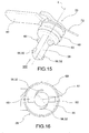
Figure 15 is a perspective view of a safety connector according to a further embodiment of this invention; -
Figure 16 is a plan view from below of the safety connector ofFigure 15 , from the side of the arrow XVI ofFigure 15 ; -
Figure 17 is a perspective view of a detail of an electric apparatus suitable to receive a portion of a safety connector according to this invention; -
Figure 18 is a perspective view of the safety connector ofFigure 15 in a first assembly configuration of an electric apparatus according to this invention; -
Figure 19 is a perspective view, partially in section, of the electric apparatus ofFigure 18 , in a subsequent assembly step of the safety connector; -
Figure 20 is a perspective view of the safety connector ofFigure 15 in assembly and closure configuration on an electric apparatus according to an embodiment of this invention; -
Figure 21 is a partial sectional view of the apparatus ofFigure 20 , in an assembly and closure configuration; -
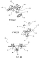
Figures 22-23 are perspective views of a safety connector according a further embodiment of the present invention; -
Figure 24 is a cross sectional view of the safety connector offigures 22-23 ; -
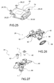
Figure 25 is a perspective view of a cover or lid adapted to receive the safety connector according to the embodiment offigures 22-24 ; -
Figures 26-27 are perspective views of a safety connector according a further embodiment of the present invention; -
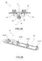
Figure 28 is a cross sectional view of the safety connector offigures 26-27 ; -
Figure 29 is a perspective view of a cover or lid adapted to receive the safety connector according to the embodiment offigures 26-28 . - The members, or parts of members, in common between the embodiments described below will be indicated with the same reference numbers.
- With reference to the above figures,
reference number 4 globally indicates an overall schematic view of an electric apparatus according to this invention. - For the purposes of the scope of protection of this invention, the specific type of electronic apparatus, understood to be, preferably but not exclusively, an electric apparatus for automotive applications, is not relevant.
- The
electric apparatus 4 comprises anelectric circuit 8 comprising at least one pair ofterminals terminals - The
electric apparatus 4 also comprises acover 16 that covers saidelectric circuit 8 so as to prevent access when thecover 16 is disposed in assembly configuration to cover theelectric circuit 8. In other words, thecover 16 has the function of physically preventing access to parts of the liveelectric circuit 8 so as to prevent the risk of an operator receiving an electric shock. - The
cover 16 is mechanically fixed in place by a plurality of attachment means 20. - The attachment means 20 may comprise screws and
bolts having heads 22 that rest on anouter wall 24 of the cover, opposite to theelectric circuit 8. - Advantageously, the
electric apparatus 4 comprises asafety connector 28 associated to thecover 16 and provided with anelectric conductor element 32; thesafety connector 28 passes through thecover 16 so as to intercept and short-circuit theterminals - The
safety connector 28 is provided with aprojection 36 that supports theelectric conductor element 32 and is movable from a closed configuration, in which it short-circuits theterminals terminals 12, 14 (thus leaving the circuit electrically open). - With the word 'movable' it is intended that the
safety connector 28 can be at least partially removed from thecover 16 so as not to short-circuit theterminals - For example, the
projection 36 passes through anengagement hole 38 of thecover 16 so as to intercept theterminals electrical circuit 8. - Advantageously, the
safety connector 28 is provided with acover element 40 that, in said closed configuration, at least partially overlaps at least one of said attachment means 20 of thecover 16, preventing its removal. In other words, in the closed configuration thecover element 40 is superimposed at least partially on at least one of the attachment means 20, for example overlying ahead 22 of an attachment means 20 so as to prevent the operator from reaching the head with a tool such as a screwdriver or a spanner, and/or to prevent, in any case, the operator from removing the attachment means 20 and thus thecover 16 itself. In fact, if it is not possible to remove all the attachment means 20 of thecover 16, it will not even be possible to remove thecover 16 and, therefore, physical access theelectric circuit 8, as long as thesafety connector 28 and thecorresponding cover element 40 are not moved from the closed configuration. - In the description and accompanying figures, a single attachment means 20 is always shown intercepted and/or surmounted by said
cover element 40; for the purposes of this invention, it is also possible to provide that two or more attachment means 20 can be surmounted, intercepted and therefore in position by thecover element 40 as long as thesafety connector 28 is disposed in the closed position. In this way, for example, the safety of the device is increased since it extends the time the operator needs to disassemble all the attachment means after having rotated/moved thesafety connector 28 and thus after opening the electric circuit. In other words it further increases the discharge time of the capacitors of theelectric circuit 8, before the operator can come in contact with it. - Therefore, the
cover element 40 is superimposed on thecover 16, on the side opposite theelectric circuit 8, i.e., on the side of saidouter wall 24 of the cover itself. - Preferably, the
cover element 40 is configured as a gripping element so as to allow both the gripping/movement of thesafety connector 28 and the blocking of the removal at least one of the attachment means 20 of thecover 16. - According to a possible embodiment of the present invention, the
safety connector 28 is axially inserted, through thecover 16 by means of a shape coupling; according to an embodiment said shape coupling is a prismatic coupling which enables an axial insertion of thesafety connector 28 within thecover 16 parallel to an axial direction of insertion Y-Y. In this embodiment, thesafety connector 28 can be at least partially removed from thecover 16 so as not to short-circuit theterminals cover 16. In this way, in fact, theelectric conductor element 32 is physically detached from theterminals safety connector 28 is fixed to therelative lid 16 by means ofscrews 42; preferablysuch screws 42 are captive screws. - According to a possible embodiment of the present invention, the
safety connector 28 is rotatably attached to thecover 16 with respect to an axis of rotation X-X, so as to rotate from the open position, in which theprojection 36 is offset with respect to theterminals cover element 40 is offset with respect to at least one of the attachment means 20 of thelid 16, to the closed position in which theprojection 36 short-circuits theterminals cover element 40 overlaps at least one of the attachment means 20. - In this embodiment, the
safety connector 28 can be rotated within thecover 16, without being removed from the cover so as not to short-circuit theterminals - For example, the
projection 36 and thecover element 40 are joined together by connection means 44, so as to be mutually detachable. For example, the connection means may comprise teeth, fins or tabs that create a mutual shape connection, preferably of the snap type. - As seen, the
projection 36 has the function of short-circuiting theterminals 12,14: for example, theprojection 36 comprises a spring 48 in conductive material fitted with a pair of projectingflexible tabs 52 that, in the closed configuration, short-circuit saidterminals terminals electric circuit 8 open. - According to a further embodiment, the
projection 36 is fitted with a pair of conductor plates 56 diametrically opposite and electrically connected to each other, so that, in the closed configuration, the conductor plates 56 are facing and electrically connected to theterminals terminals - According to an embodiment, the
projection 36 is provided with at least oneretention tooth 60, counter-shaped to acorresponding seat 62 on thecover 16 made at theengagement hole 38, in which theretention tooth 60 allows the insertion of theprojection 36 through theseat 62 when thesafety connector 28 is in the open position, and abuts against astop wall 64 of thecover 16 so as to prevent the removal of thesafety connector 28 from theseat 62 in the closed configuration. - Preferably, the
projection 36 is provided with tworetention teeth 60 counter-shaped torespective seats 62 on thecover 16 formed in correspondence of theengagement hole 38. Theretention teeth 60 can be different from each other, each associated to a correspondingcounter-shaped seat 62, so as to ensure a proper assembly of thesafety connector 28 on thecover 16. - For example, the
stop wall 64 is facing theelectric circuit 8 and opposite to theouter wall 24 of thecover 16. - According to an embodiment, between the
safety connector 28 and anouter wall 24 of thecover 16, opposite theelectric circuit 8, agasket 68 associated with thesafety connector 28 is placed next to saidengagement hole 38, so as to seal closed the connection between thesafety connector 28 and thecover 16. - Preferably, the
gasket 68 is placed and/or shaped so as to be influenced in compression when theretention tooth 60 crosses theseat 62 and stops in abutment against thestop wall 64 of thecover 16. - According to an embodiment, the portion of
cover 16 that delimits theengagement hole 38 has a truncated cone shape that narrows towards theelectric circuit 8. - This truncated cone configuration ensures a uniform compression of the
gasket 68 and improves the overall hermetic seal of the coupling of thesafety connector 28. - The
terminals electric circuit 8 are, for example, supported bybase plates 70 at least partially counter-shaped to theprojection 36 of thesafety connector 28, so as to support the mechanical contact between theterminals projection 36 in the closed configuration of thesafety connector 28. - According to a possible embodiment, the
safety connector 28 is fitted with areturn spring 72 that influences the safety connector to move into the open configuration. - In other words, if the operator does not hook the
safety connector 28 well with respect to thecover 16, the return spring elastically returns the safety connector to the open position of theelectric circuit 8. - According to an embodiment, the
cover 16 is provided with a limit switch inopening 76, which projects from thecover 16 from the opposite side to theelectric circuit 8 in order to achieve the maximum displacement when opening thesafety connector 28 in order to allow free access and the removal of the attachment means 20 influenced by thecover element 40 in the closed configuration. - Preferably, the
cover 16 is provided with a limit switch in closing 80, which projects from thecover 16 from the opposite side to theelectric circuit 8 in order to achieve the maximum displacement when closing thesafety connector 28 in order to prevent free access and the removal of the attachment means 20 influenced by thecover element 40 in the closed configuration. - Preferably, the
cover 16 is fitted with a lockingelement 84, which projects from thecover 16 on the opposite side to theelectric circuit 8 in order to allow the coupling of a correspondingtab 88 of thecover element 40, when thesafety connector 28 is moved into the closed configuration. - For example, the
tab 88 is elastically flexible so as to snap engage the lockingelement 84 when thesafety connector 28 is moved into the closed configuration. - Preferably, the locking
element 84 and/or thetab 88 comprises chamfers or guides 90 which favour their reciprocal engagement in the closing movement/rotation of thesafety connector 28; this mutual coupling is also favoured by the elastic deformation of thetab 88 under the thrust received from the impact against the lockingelement 84. - Also, preferably, the
tab 88 comprises an undercut 92 which abuts against the lockingelement 84 in order to prevent accidental opening of thesafety connector 28. - As described above, the attachment means 20 may be a screw or bolt 22 whose head is surmounted by the
cover element 40 in the closed configuration of thesafety connector 28. - According to an embodiment, the
cover element 40 is configured with areinforcement wall 96, substantially perpendicular to thecover 16 in order to create a reinforcement for thecover element 40 and an end stroke for the movement of thesafety connector 28. - For example, the
reinforcement wall 96 comprises arecess 98 suitable to allow the bypassing of the limit switch inopening 76, associated with thecover 16 to set the maximum displacement in opening of thesafety connector 28. - According to an embodiment, the
reinforcement wall 96 comprises anabutment 100 suitable to interface with the limit switch in closing 80, associated with thecover 16 to set the maximum displacement in closing of thesafety connector 28. - According to a possible embodiment of this invention, the attachment means 20 intercepted by the
cover element 40 comprise a slider (not shown) that, following the removal of said attachment means 20, projects from anouter wall 24 of thecover 16 in order to interfere with thecover element 40, preventing the assembly of thesafety connector 28 in case of non-installation of the attachment means 20. In this way, it is avoided that the operator may forget to reassemble the apparatus without screwing the attachment means 20 normally intercepted by the cover element; in fact, if this is the case, the operator himself would be able to subsequently disassemble the cover, remove it without have to wait for the removal of said attachment means 20 and there would not be the time required for the capacitors to discharge. - According to an embodiment, the attachment means 20 are captive screws, i.e., special screws that require the use of appropriate tools in order to be removed from the
relative cover 16. Such captive screws are, in fact, shaped so that they cannot be easily separated from the plate with the hole in which they are inserted; this effect, in a known manner, can be obtained by a suitable shaping of the stem and/or of the head in order to obtain suitable undercuts that constrain the screw preventing it from being easily removed. - In this way, it is avoided that the operator can lose said screws in the steps of disassembly and reassembly of the
cover 16. - We will now describe the functioning, as well as the technique of maintaining, the electric apparatus provided with safety device according to this invention.
- In particular, in the closed configuration of the
cover 16 and thesafety connector 28, the electric circuit is protected from the outside and electrically short-circuited by means of theelectric conductor element 32 that interfaces with theterminals elastic tabs 52 or conductor plates 56 bring each other into contact with arespective terminal safety connector 28 on thecover 16 is for example obtained by means of a coupling between the lockingelement 84 and/or thetab 88. The possible presence of the undercut 92 which abuts against the lockingelement 84, prevents accidental opening of thesafety connector 28. This mechanical connection remains fixed even in case of shock, vibration and the like. - In addition, the
gasket 68 ensures the hermetic seal of thesafety connector 28 on thecover 16 and hence the hermetic seal of theelectric circuit 8. - The possible extraction of the
safety device 28 from the cover is prevented by the abutment between at least oneretention tooth 60 and thestop wall 64 of thecover 16. In fact, until thesafety device 28 is in the closed position, theretention 60 is offset with respect to therespective seat 62 on theengagement hole 38 and thus cannot be extracted. - If it is necessary to maintain the
electric circuit 8, it will be necessary to access theelectric circuit 8 safely. - In this regard, it is necessary to remove all the attachment means 20. It is clear that, in order to remove at least one of the attachment means 20 of the cover, one is forced to move/rotate the
safety device 28 in the open position. Doing this requires first unhooking the coupling between the lockingelement 84 and/or thetab 88. So, one moves/rotates thesafety device 28 in the open position; in this way, the electric circuit is opened when theelastic tabs 52 and/or the conductor plates 56 are offset with respect to theterminals - Thus, the discharge of the capacitors of the
electric circuit 8 begins. In the meantime, the operator can extract thesafety connector 28 from thecover 16, after having first aligned theretention teeth 60 with therelative seats 62. Thus, the operator also has free access to the retention means 20 previously intercepted/surmounted by thecover element 40. The removal of the last attachment means 20 also allows the removal of thecover 16 and thus access to theelectric circuit 8, which will be completely or substantially discharged of electricity and can be handled safely by the operator. - As can be appreciated from the description, the electric apparatus with safety connector according to the invention allows overcoming the drawbacks presented in the prior art.
- In fact, the safety connector of this invention allows ensuring operator safety while maintaining the production and assembly costs of the component low.
- In fact, the functions of the components of the device are separated and simplified.
- The cover has the sole function of preventing access to mechanical parts normally live: so, the cover physically closes access to live parts without requiring any parts that can interact directly with live portions. In other words, the cover does not comprise live portions that constitute parts of the electric circuit. This also constitutes a further safety device for the operator since the cover itself is never live (so there is no risk of eddy currents that can pass through the cover and be discharged on the operator.
- The connector, in turn, has the sole function of opening/closing the electric circuit and has no mechanical locking function of the cover.
- In addition, the connector performs the protection function because, when it is in the closed position, it intercepts at least one mechanical attachment means of the cover, making it impossible to removal.
- In this way, one obtains safety for the operator while keeping the costs of the device low.
- Furthermore, the safety connector according to the invention is simple and economical to produce.
- A person skilled in the art, in order to satisfy contingent and specific needs, may make numerous modifications and variations to the electric apparatuses and safety devices described above, all however contained within the scope of the invention as defined by the following claims.
Claims (16)
- Electric apparatus (4) with safety connector (28) for preventing electric shock, comprising:- an electric circuit (8) comprising at least one pair of terminals (12, 14) electrically separate from each other so as to keep the electric circuit (8) open,- a cover (16) covering said electric circuit (8) so as to preclude access when the cover (16) is placed in the assembled configuration to cover the electric circuit (8), the cover (16) being mechanically fixed into place using a plurality of attachment means (20),- a safety connector (28) associated with the cover (16) and equipped with an electrical conductor element (32), wherein the safety connector (28) crosses the cover (16) so as to intercept and short-circuit the terminals (12, 14),characterised in that- the safety connector (28) is provided with a projection (36) which supports the electric conductor element (32) and which is movable from a closed configuration in which it short-circuits the terminals (12,14) to an open position in which it does not short circuit the terminals (12,14),- the safety connector (28) is provided with a cover element (40) which, in said closed configuration, at least partially overlaps at least one of said attachment means (20) of the cover (16), preventing the removal thereof.
- Electrical apparatus (4) according to claim 1, wherein said cover element (40) is configured as a gripping element so as to allow both the gripping/movement of the safety connector (28) and the blocking of the removal at least one of the means of attachment (20) of the cover (16).
- Electrical apparatus (4) according to claim 1 or 2, wherein the safety connector (28) is axially inserted, through the cover (16) by means of a shape coupling parallel to an axial direction of insertion (Y-Y).
- Electrical apparatus (4) according to claim 3, wherein said shape coupling is a prismatic coupling.
- Electrical apparatus (4) according to claim 1, 2 or 3, wherein the safety connector (28) is rotatably attached to the cover (16) with respect to an axis of rotation (X-X), so as to rotate from the open position in which the projection (36) is offset with respect to the terminals (12,14) so as not to short-circuit them, and the cover element (40) is offset with respect to at least one of the attachment means (20) of the lid (16), to the closed position wherein the projection (36) short-circuits the terminals (12,14) and the cover element (40) overlaps at least one of the attachment means (20).
- Electric apparatus (4) according to any of the previous claims, wherein the projection (36) comprises a spring (48) in electrically conductive material fitted with a pair of projecting flexible tabs (52) which in the closed configuration short-circuit said terminals (12,14) and which in the open configuration, are offset with respect to the terminals (12,14).
- Electric apparatus (4) according to any of the claims from 1 to 5, wherein the projection (36) is fitted with a pair of conductor plates (56) diametrically opposite and electrically connected to each other, so that, in the closed configuration, the conductor plates (56) are facing and electrically connected to the terminals (12, 14) and in the open configuration, said conductor plates (56) are offset with respect to the terminals (12, 14).
- Electric apparatus (4) according to any of the previous claims wherein the cover element (40) is superposed on the cover (16), on the opposite side to the electric circuit (8) and the projection (36) passes through an engagement hole (38) of the cover (16) so as to intercept the terminals (12, 14) of the electric circuit (8).
- Electrical apparatus (4) according to claim 8, wherein the projection (36) is provided with at least one retention tooth (60), counter-shaped to a corresponding seat (62) on the cover (16) made at the engagement hole (38), wherein the retention tooth (60) allows the insertion of the projection (36) through the seat (62) when the safety connector (28) is in the open position, and abuts against a stop wall (64) of the cover (16) so as to prevent the removal of the safety connector (28) from the seat (62) in the closed configuration.
- Electric apparatus (4) according to any of the claims from 8 to 9, wherein between the safety connector (28) and an outer wall (24) of the cover (16) opposite the electric circuit (8), a gasket (68) associated with the safety connector (28) is placed next to said engagement hole (38), so as to seal closed the connection between the safety connector (28) and the cover (16).
- Electric apparatus (4) according to any of the previous claims, wherein the terminals (12, 14) of the electric circuit (8) are supported by base plates (70) at least partially counter-shaped to the projection (36) of the safety connector (28), so as to support the mechanical contact between the terminals (12, 14) and the projection (36) in the closed configuration of the safety connector (28).
- Electric apparatus (4) according to any of the previous claims wherein the cover (16) is provided with a limit switch in opening (76), which projects from the cover (16) from the opposite side to the electric circuit (8) in order to achieve the maximum displacement when opening the safety connector (28) in order to allow free access and the removal of at least one means of attachment (20) influenced by the cover element (40) in the closed configuration.
- Electric apparatus (4) according to any of the previous claims wherein the cover (16) is provided with a limit switch in closing (80), which projects from the cover (16) from the opposite side to the electric circuit (8) in order to achieve the maximum displacement when closing the safety connector (28) in order to prevent free access and the removal of the means of attachment (20) influenced by the cover element (40) in the closed configuration.
- Electric apparatus (4) according to any of the previous claims wherein the cover (16) is fitted with a locking element (84), which projects from the cover (16) on the opposite side to the electric circuit (8) in order to allow the coupling of a corresponding tab (88) of the cover element (40), when the safety connector (28) is moved into the closed configuration.
- Electric apparatus (4) according to any of the previous claims wherein the cover element (40) is configured with a reinforcement wall (96), substantially perpendicular to the cover (16) in order to create a reinforcement for the cover element (40) and an end stroke for the movement of the safety connector (28), wherein said reinforcement wall (96) comprises a recess (98) suitable to allow the bypassing of a limit switch in opening (76), associated with the cover (16) to set the maximum displacement in opening of the safety connector (28).
- Electric apparatus (4) according to any of the previous claims, wherein the attachment means (20) intercepted by the cover element (40) comprise a slider which, following the removal of said attachment means (20), projects from an outer wall (24) of the cover (16) in order to interfere with the cover element (40), preventing the assembly of the safety connector (28) in case of non-installation of the attachment means (20).
Applications Claiming Priority (1)
| Application Number | Priority Date | Filing Date | Title |
|---|---|---|---|
| ITPD20140330 | 2014-11-28 |
Publications (2)
| Publication Number | Publication Date |
|---|---|
| EP3026763A1 true EP3026763A1 (en) | 2016-06-01 |
| EP3026763B1 EP3026763B1 (en) | 2017-02-22 |
Family
ID=52444501
Family Applications (1)
| Application Number | Title | Priority Date | Filing Date |
|---|---|---|---|
| EP15196194.3A Active EP3026763B1 (en) | 2014-11-28 | 2015-11-25 | Electric apparatus with safety connector for preventing electric shock |
Country Status (3)
| Country | Link |
|---|---|
| US (1) | US9564702B2 (en) |
| EP (1) | EP3026763B1 (en) |
| CN (1) | CN105655834B (en) |
Cited By (2)
| Publication number | Priority date | Publication date | Assignee | Title |
|---|---|---|---|---|
| CN108493061A (en) * | 2018-05-23 | 2018-09-04 | 广东珠电气科技有限公司 | One kind preventing reversed highly reliable leakage circuit breakers |
| WO2020126723A1 (en) * | 2018-12-17 | 2020-06-25 | Robert Bosch Gmbh | High-voltage device |
Families Citing this family (2)
| Publication number | Priority date | Publication date | Assignee | Title |
|---|---|---|---|---|
| EP3026763B1 (en) * | 2014-11-28 | 2017-02-22 | Magneti Marelli S.p.A. | Electric apparatus with safety connector for preventing electric shock |
| JP6527908B2 (en) * | 2017-05-25 | 2019-06-05 | 矢崎総業株式会社 | Connector device |
Citations (5)
| Publication number | Priority date | Publication date | Assignee | Title |
|---|---|---|---|---|
| GB524449A (en) * | 1939-01-28 | 1940-08-07 | Vernon Hope | Improvements in or relating to electric fuses |
| GB974763A (en) * | 1960-09-16 | 1964-11-11 | Lowe & Fletcher Ltd | Improvements in or relating to locks |
| US4930918A (en) * | 1987-10-16 | 1990-06-05 | Mannesmann Aktiengesellschaft | Office machine, in particular matrix printer |
| US20020114117A1 (en) * | 2001-02-21 | 2002-08-22 | Edwin Milanczak | Fused electrical disconnect device for high current applications |
| JP2014011821A (en) * | 2012-06-27 | 2014-01-20 | Mitsubishi Electric Corp | Connection box and photovoltaic power generation system |
Family Cites Families (7)
| Publication number | Priority date | Publication date | Assignee | Title |
|---|---|---|---|---|
| US5376017A (en) * | 1992-09-29 | 1994-12-27 | Sumitomo Wiring Systems, Ltd. | Connector |
| KR100564091B1 (en) * | 2000-03-01 | 2006-03-27 | 니혼 앗사쿠단시세이조 가부시키가이샤 | Electrical connection system |
| JP3607883B2 (en) * | 2001-06-22 | 2005-01-05 | 日本圧着端子製造株式会社 | Electrical connection device with latch |
| JP4034125B2 (en) * | 2002-06-06 | 2008-01-16 | 日本圧着端子製造株式会社 | Electrical connection device |
| JP4310663B1 (en) * | 2008-01-31 | 2009-08-12 | 三菱自動車工業株式会社 | Service plug mounting structure |
| US9653842B2 (en) * | 2014-05-09 | 2017-05-16 | Textron Inc. | Water resistant USB connection system for vehicles |
| EP3026763B1 (en) * | 2014-11-28 | 2017-02-22 | Magneti Marelli S.p.A. | Electric apparatus with safety connector for preventing electric shock |
-
2015
- 2015-11-25 EP EP15196194.3A patent/EP3026763B1/en active Active
- 2015-11-25 US US14/951,981 patent/US9564702B2/en active Active
- 2015-11-30 CN CN201510857539.3A patent/CN105655834B/en active Active
Patent Citations (5)
| Publication number | Priority date | Publication date | Assignee | Title |
|---|---|---|---|---|
| GB524449A (en) * | 1939-01-28 | 1940-08-07 | Vernon Hope | Improvements in or relating to electric fuses |
| GB974763A (en) * | 1960-09-16 | 1964-11-11 | Lowe & Fletcher Ltd | Improvements in or relating to locks |
| US4930918A (en) * | 1987-10-16 | 1990-06-05 | Mannesmann Aktiengesellschaft | Office machine, in particular matrix printer |
| US20020114117A1 (en) * | 2001-02-21 | 2002-08-22 | Edwin Milanczak | Fused electrical disconnect device for high current applications |
| JP2014011821A (en) * | 2012-06-27 | 2014-01-20 | Mitsubishi Electric Corp | Connection box and photovoltaic power generation system |
Cited By (5)
| Publication number | Priority date | Publication date | Assignee | Title |
|---|---|---|---|---|
| CN108493061A (en) * | 2018-05-23 | 2018-09-04 | 广东珠电气科技有限公司 | One kind preventing reversed highly reliable leakage circuit breakers |
| CN108493061B (en) * | 2018-05-23 | 2024-05-10 | 广东一珠电气科技有限公司 | Anti-reverse high-reliability leakage circuit breaker |
| WO2020126723A1 (en) * | 2018-12-17 | 2020-06-25 | Robert Bosch Gmbh | High-voltage device |
| CN113169475A (en) * | 2018-12-17 | 2021-07-23 | 罗伯特·博世有限公司 | High-voltage device |
| US11638358B2 (en) | 2018-12-17 | 2023-04-25 | Robert Bosch Gmbh | High-voltage device |
Also Published As
| Publication number | Publication date |
|---|---|
| CN105655834B (en) | 2019-03-19 |
| CN105655834A (en) | 2016-06-08 |
| US9564702B2 (en) | 2017-02-07 |
| EP3026763B1 (en) | 2017-02-22 |
| US20160156120A1 (en) | 2016-06-02 |
Similar Documents
| Publication | Publication Date | Title |
|---|---|---|
| EP3026763B1 (en) | Electric apparatus with safety connector for preventing electric shock | |
| US20240186657A1 (en) | Inter-terminal connection structure | |
| MXPA96006393A (en) | Electric connection pin | |
| EP2830161B1 (en) | Quick connect power connector | |
| US6328581B1 (en) | Universal electric adapter | |
| US20180076534A1 (en) | Connector | |
| US8379375B2 (en) | Power source circuit shut off device | |
| JP6709513B2 (en) | Terminal block | |
| JPH09219239A (en) | Electric connector plug | |
| JP2014049376A (en) | Connector connecting structure | |
| EP2988399A2 (en) | Fastening system for a terminal box and electrical machine | |
| US20180316123A1 (en) | Seal cover | |
| US6196858B1 (en) | Circuit breaking device | |
| US20180342833A1 (en) | Connector device | |
| US9640916B2 (en) | Shield connector | |
| CN102119471A (en) | electrical connector | |
| US10036567B2 (en) | Ventilator having an electrical connection device | |
| CN108630504B (en) | High amperage circuit breaker with terminal insulating fastener cap | |
| US20200203940A1 (en) | Opening closure device for case | |
| KR20160040942A (en) | A battery terminal cover for vehicle | |
| US10665994B2 (en) | Multiple-contact plug with an integrated short-circuit link element | |
| US11652305B2 (en) | Electrical assembly | |
| CN212486810U (en) | Electric heating device | |
| CN115039274B (en) | Motor vehicle battery assembly including an interlocking device for protecting two connection terminals | |
| EA014393B1 (en) | Electrical plug-in connector |
Legal Events
| Date | Code | Title | Description |
|---|---|---|---|
| PUAI | Public reference made under article 153(3) epc to a published international application that has entered the european phase |
Free format text: ORIGINAL CODE: 0009012 |
|
| AK | Designated contracting states |
Kind code of ref document: A1 Designated state(s): AL AT BE BG CH CY CZ DE DK EE ES FI FR GB GR HR HU IE IS IT LI LT LU LV MC MK MT NL NO PL PT RO RS SE SI SK SM TR |
|
| AX | Request for extension of the european patent |
Extension state: BA ME |
|
| 17P | Request for examination filed |
Effective date: 20160729 |
|
| RBV | Designated contracting states (corrected) |
Designated state(s): AL AT BE BG CH CY CZ DE DK EE ES FI FR GB GR HR HU IE IS IT LI LT LU LV MC MK MT NL NO PL PT RO RS SE SI SK SM TR |
|
| REG | Reference to a national code |
Ref country code: DE Ref legal event code: R079 Ref document number: 602015001565 Country of ref document: DE Free format text: PREVIOUS MAIN CLASS: H01R0013710000 Ipc: H01H0027080000 |
|
| GRAP | Despatch of communication of intention to grant a patent |
Free format text: ORIGINAL CODE: EPIDOSNIGR1 |
|
| RIC1 | Information provided on ipc code assigned before grant |
Ipc: H01H 27/08 20060101AFI20160906BHEP Ipc: H01R 13/635 20060101ALN20160906BHEP Ipc: H01R 13/703 20060101ALI20160906BHEP |
|
| RIC1 | Information provided on ipc code assigned before grant |
Ipc: H01R 13/635 20060101ALN20160909BHEP Ipc: H01R 13/703 20060101ALI20160909BHEP Ipc: H01H 27/08 20060101AFI20160909BHEP |
|
| INTG | Intention to grant announced |
Effective date: 20160930 |
|
| RIC1 | Information provided on ipc code assigned before grant |
Ipc: H01R 13/703 20060101ALI20160919BHEP Ipc: H01H 27/08 20060101AFI20160919BHEP Ipc: H01R 13/635 20060101ALN20160919BHEP |
|
| GRAS | Grant fee paid |
Free format text: ORIGINAL CODE: EPIDOSNIGR3 |
|
| GRAA | (expected) grant |
Free format text: ORIGINAL CODE: 0009210 |
|
| AK | Designated contracting states |
Kind code of ref document: B1 Designated state(s): AL AT BE BG CH CY CZ DE DK EE ES FI FR GB GR HR HU IE IS IT LI LT LU LV MC MK MT NL NO PL PT RO RS SE SI SK SM TR |
|
| REG | Reference to a national code |
Ref country code: GB Ref legal event code: FG4D |
|
| REG | Reference to a national code |
Ref country code: CH Ref legal event code: EP |
|
| REG | Reference to a national code |
Ref country code: AT Ref legal event code: REF Ref document number: 869849 Country of ref document: AT Kind code of ref document: T Effective date: 20170315 |
|
| REG | Reference to a national code |
Ref country code: IE Ref legal event code: FG4D |
|
| REG | Reference to a national code |
Ref country code: DE Ref legal event code: R096 Ref document number: 602015001565 Country of ref document: DE |
|
| REG | Reference to a national code |
Ref country code: LT Ref legal event code: MG4D |
|
| REG | Reference to a national code |
Ref country code: NL Ref legal event code: MP Effective date: 20170222 |
|
| REG | Reference to a national code |
Ref country code: AT Ref legal event code: MK05 Ref document number: 869849 Country of ref document: AT Kind code of ref document: T Effective date: 20170222 |
|
| PG25 | Lapsed in a contracting state [announced via postgrant information from national office to epo] |
Ref country code: FI Free format text: LAPSE BECAUSE OF FAILURE TO SUBMIT A TRANSLATION OF THE DESCRIPTION OR TO PAY THE FEE WITHIN THE PRESCRIBED TIME-LIMIT Effective date: 20170222 Ref country code: NO Free format text: LAPSE BECAUSE OF FAILURE TO SUBMIT A TRANSLATION OF THE DESCRIPTION OR TO PAY THE FEE WITHIN THE PRESCRIBED TIME-LIMIT Effective date: 20170522 Ref country code: GR Free format text: LAPSE BECAUSE OF FAILURE TO SUBMIT A TRANSLATION OF THE DESCRIPTION OR TO PAY THE FEE WITHIN THE PRESCRIBED TIME-LIMIT Effective date: 20170523 Ref country code: LT Free format text: LAPSE BECAUSE OF FAILURE TO SUBMIT A TRANSLATION OF THE DESCRIPTION OR TO PAY THE FEE WITHIN THE PRESCRIBED TIME-LIMIT Effective date: 20170222 Ref country code: HR Free format text: LAPSE BECAUSE OF FAILURE TO SUBMIT A TRANSLATION OF THE DESCRIPTION OR TO PAY THE FEE WITHIN THE PRESCRIBED TIME-LIMIT Effective date: 20170222 |
|
| PG25 | Lapsed in a contracting state [announced via postgrant information from national office to epo] |
Ref country code: SE Free format text: LAPSE BECAUSE OF FAILURE TO SUBMIT A TRANSLATION OF THE DESCRIPTION OR TO PAY THE FEE WITHIN THE PRESCRIBED TIME-LIMIT Effective date: 20170222 Ref country code: ES Free format text: LAPSE BECAUSE OF FAILURE TO SUBMIT A TRANSLATION OF THE DESCRIPTION OR TO PAY THE FEE WITHIN THE PRESCRIBED TIME-LIMIT Effective date: 20170222 Ref country code: PT Free format text: LAPSE BECAUSE OF FAILURE TO SUBMIT A TRANSLATION OF THE DESCRIPTION OR TO PAY THE FEE WITHIN THE PRESCRIBED TIME-LIMIT Effective date: 20170622 Ref country code: LV Free format text: LAPSE BECAUSE OF FAILURE TO SUBMIT A TRANSLATION OF THE DESCRIPTION OR TO PAY THE FEE WITHIN THE PRESCRIBED TIME-LIMIT Effective date: 20170222 Ref country code: RS Free format text: LAPSE BECAUSE OF FAILURE TO SUBMIT A TRANSLATION OF THE DESCRIPTION OR TO PAY THE FEE WITHIN THE PRESCRIBED TIME-LIMIT Effective date: 20170222 Ref country code: AT Free format text: LAPSE BECAUSE OF FAILURE TO SUBMIT A TRANSLATION OF THE DESCRIPTION OR TO PAY THE FEE WITHIN THE PRESCRIBED TIME-LIMIT Effective date: 20170222 Ref country code: NL Free format text: LAPSE BECAUSE OF NON-PAYMENT OF DUE FEES Effective date: 20170222 Ref country code: BG Free format text: LAPSE BECAUSE OF FAILURE TO SUBMIT A TRANSLATION OF THE DESCRIPTION OR TO PAY THE FEE WITHIN THE PRESCRIBED TIME-LIMIT Effective date: 20170522 |
|
| REG | Reference to a national code |
Ref country code: FR Ref legal event code: PLFP Year of fee payment: 3 |
|
| PG25 | Lapsed in a contracting state [announced via postgrant information from national office to epo] |
Ref country code: RO Free format text: LAPSE BECAUSE OF FAILURE TO SUBMIT A TRANSLATION OF THE DESCRIPTION OR TO PAY THE FEE WITHIN THE PRESCRIBED TIME-LIMIT Effective date: 20170222 Ref country code: CZ Free format text: LAPSE BECAUSE OF FAILURE TO SUBMIT A TRANSLATION OF THE DESCRIPTION OR TO PAY THE FEE WITHIN THE PRESCRIBED TIME-LIMIT Effective date: 20170222 Ref country code: EE Free format text: LAPSE BECAUSE OF FAILURE TO SUBMIT A TRANSLATION OF THE DESCRIPTION OR TO PAY THE FEE WITHIN THE PRESCRIBED TIME-LIMIT Effective date: 20170222 Ref country code: SK Free format text: LAPSE BECAUSE OF FAILURE TO SUBMIT A TRANSLATION OF THE DESCRIPTION OR TO PAY THE FEE WITHIN THE PRESCRIBED TIME-LIMIT Effective date: 20170222 |
|
| REG | Reference to a national code |
Ref country code: DE Ref legal event code: R097 Ref document number: 602015001565 Country of ref document: DE |
|
| PG25 | Lapsed in a contracting state [announced via postgrant information from national office to epo] |
Ref country code: PL Free format text: LAPSE BECAUSE OF FAILURE TO SUBMIT A TRANSLATION OF THE DESCRIPTION OR TO PAY THE FEE WITHIN THE PRESCRIBED TIME-LIMIT Effective date: 20170222 Ref country code: DK Free format text: LAPSE BECAUSE OF FAILURE TO SUBMIT A TRANSLATION OF THE DESCRIPTION OR TO PAY THE FEE WITHIN THE PRESCRIBED TIME-LIMIT Effective date: 20170222 Ref country code: SM Free format text: LAPSE BECAUSE OF FAILURE TO SUBMIT A TRANSLATION OF THE DESCRIPTION OR TO PAY THE FEE WITHIN THE PRESCRIBED TIME-LIMIT Effective date: 20170222 |
|
| PLBE | No opposition filed within time limit |
Free format text: ORIGINAL CODE: 0009261 |
|
| STAA | Information on the status of an ep patent application or granted ep patent |
Free format text: STATUS: NO OPPOSITION FILED WITHIN TIME LIMIT |
|
| 26N | No opposition filed |
Effective date: 20171123 |
|
| PG25 | Lapsed in a contracting state [announced via postgrant information from national office to epo] |
Ref country code: SI Free format text: LAPSE BECAUSE OF FAILURE TO SUBMIT A TRANSLATION OF THE DESCRIPTION OR TO PAY THE FEE WITHIN THE PRESCRIBED TIME-LIMIT Effective date: 20170222 |
|
| PG25 | Lapsed in a contracting state [announced via postgrant information from national office to epo] |
Ref country code: MC Free format text: LAPSE BECAUSE OF FAILURE TO SUBMIT A TRANSLATION OF THE DESCRIPTION OR TO PAY THE FEE WITHIN THE PRESCRIBED TIME-LIMIT Effective date: 20170222 |
|
| PG25 | Lapsed in a contracting state [announced via postgrant information from national office to epo] |
Ref country code: LU Free format text: LAPSE BECAUSE OF NON-PAYMENT OF DUE FEES Effective date: 20171125 |
|
| REG | Reference to a national code |
Ref country code: BE Ref legal event code: MM Effective date: 20171130 |
|
| REG | Reference to a national code |
Ref country code: IE Ref legal event code: MM4A |
|
| PG25 | Lapsed in a contracting state [announced via postgrant information from national office to epo] |
Ref country code: MT Free format text: LAPSE BECAUSE OF NON-PAYMENT OF DUE FEES Effective date: 20171125 |
|
| REG | Reference to a national code |
Ref country code: FR Ref legal event code: PLFP Year of fee payment: 4 |
|
| PG25 | Lapsed in a contracting state [announced via postgrant information from national office to epo] |
Ref country code: IE Free format text: LAPSE BECAUSE OF NON-PAYMENT OF DUE FEES Effective date: 20171125 |
|
| PG25 | Lapsed in a contracting state [announced via postgrant information from national office to epo] |
Ref country code: BE Free format text: LAPSE BECAUSE OF NON-PAYMENT OF DUE FEES Effective date: 20171130 |
|
| PG25 | Lapsed in a contracting state [announced via postgrant information from national office to epo] |
Ref country code: HU Free format text: LAPSE BECAUSE OF FAILURE TO SUBMIT A TRANSLATION OF THE DESCRIPTION OR TO PAY THE FEE WITHIN THE PRESCRIBED TIME-LIMIT; INVALID AB INITIO Effective date: 20151125 |
|
| REG | Reference to a national code |
Ref country code: CH Ref legal event code: PL |
|
| PG25 | Lapsed in a contracting state [announced via postgrant information from national office to epo] |
Ref country code: LI Free format text: LAPSE BECAUSE OF NON-PAYMENT OF DUE FEES Effective date: 20181130 Ref country code: CH Free format text: LAPSE BECAUSE OF NON-PAYMENT OF DUE FEES Effective date: 20181130 |
|
| PG25 | Lapsed in a contracting state [announced via postgrant information from national office to epo] |
Ref country code: CY Free format text: LAPSE BECAUSE OF FAILURE TO SUBMIT A TRANSLATION OF THE DESCRIPTION OR TO PAY THE FEE WITHIN THE PRESCRIBED TIME-LIMIT Effective date: 20170222 |
|
| PG25 | Lapsed in a contracting state [announced via postgrant information from national office to epo] |
Ref country code: MK Free format text: LAPSE BECAUSE OF FAILURE TO SUBMIT A TRANSLATION OF THE DESCRIPTION OR TO PAY THE FEE WITHIN THE PRESCRIBED TIME-LIMIT Effective date: 20170222 |
|
| PG25 | Lapsed in a contracting state [announced via postgrant information from national office to epo] |
Ref country code: AL Free format text: LAPSE BECAUSE OF FAILURE TO SUBMIT A TRANSLATION OF THE DESCRIPTION OR TO PAY THE FEE WITHIN THE PRESCRIBED TIME-LIMIT Effective date: 20170222 Ref country code: IS Free format text: LAPSE BECAUSE OF FAILURE TO SUBMIT A TRANSLATION OF THE DESCRIPTION OR TO PAY THE FEE WITHIN THE PRESCRIBED TIME-LIMIT Effective date: 20170622 |
|
| GBPC | Gb: european patent ceased through non-payment of renewal fee |
Effective date: 20191125 |
|
| PG25 | Lapsed in a contracting state [announced via postgrant information from national office to epo] |
Ref country code: GB Free format text: LAPSE BECAUSE OF NON-PAYMENT OF DUE FEES Effective date: 20191125 |
|
| PGFP | Annual fee paid to national office [announced via postgrant information from national office to epo] |
Ref country code: DE Payment date: 20251022 Year of fee payment: 11 |
|
| PGFP | Annual fee paid to national office [announced via postgrant information from national office to epo] |
Ref country code: IT Payment date: 20251022 Year of fee payment: 11 |
|
| PGFP | Annual fee paid to national office [announced via postgrant information from national office to epo] |
Ref country code: FR Payment date: 20251022 Year of fee payment: 11 |
|
| PGFP | Annual fee paid to national office [announced via postgrant information from national office to epo] |
Ref country code: TR Payment date: 20251031 Year of fee payment: 11 |