EP3026714A1 - Metal chalcogenide nanoparticles for manufacturing optical absorption layer for solar cell and method for preparing same - Google Patents
Metal chalcogenide nanoparticles for manufacturing optical absorption layer for solar cell and method for preparing same Download PDFInfo
- Publication number
- EP3026714A1 EP3026714A1 EP14844680.0A EP14844680A EP3026714A1 EP 3026714 A1 EP3026714 A1 EP 3026714A1 EP 14844680 A EP14844680 A EP 14844680A EP 3026714 A1 EP3026714 A1 EP 3026714A1
- Authority
- EP
- European Patent Office
- Prior art keywords
- solution
- metal chalcogenide
- chalcogenide nanoparticles
- phase
- nanoparticles
- Prior art date
- Legal status (The legal status is an assumption and is not a legal conclusion. Google has not performed a legal analysis and makes no representation as to the accuracy of the status listed.)
- Granted
Links
Images





Classifications
-
- H—ELECTRICITY
- H10—SEMICONDUCTOR DEVICES; ELECTRIC SOLID-STATE DEVICES NOT OTHERWISE PROVIDED FOR
- H10F—INORGANIC SEMICONDUCTOR DEVICES SENSITIVE TO INFRARED RADIATION, LIGHT, ELECTROMAGNETIC RADIATION OF SHORTER WAVELENGTH OR CORPUSCULAR RADIATION
- H10F77/00—Constructional details of devices covered by this subclass
- H10F77/10—Semiconductor bodies
- H10F77/12—Active materials
-
- H—ELECTRICITY
- H01—ELECTRIC ELEMENTS
- H01B—CABLES; CONDUCTORS; INSULATORS; SELECTION OF MATERIALS FOR THEIR CONDUCTIVE, INSULATING OR DIELECTRIC PROPERTIES
- H01B1/00—Conductors or conductive bodies characterised by the conductive materials; Selection of materials as conductors
- H01B1/02—Conductors or conductive bodies characterised by the conductive materials; Selection of materials as conductors mainly consisting of metals or alloys
-
- H—ELECTRICITY
- H01—ELECTRIC ELEMENTS
- H01B—CABLES; CONDUCTORS; INSULATORS; SELECTION OF MATERIALS FOR THEIR CONDUCTIVE, INSULATING OR DIELECTRIC PROPERTIES
- H01B1/00—Conductors or conductive bodies characterised by the conductive materials; Selection of materials as conductors
- H01B1/06—Conductors or conductive bodies characterised by the conductive materials; Selection of materials as conductors mainly consisting of other non-metallic substances
- H01B1/10—Conductors or conductive bodies characterised by the conductive materials; Selection of materials as conductors mainly consisting of other non-metallic substances sulfides
-
- H—ELECTRICITY
- H10—SEMICONDUCTOR DEVICES; ELECTRIC SOLID-STATE DEVICES NOT OTHERWISE PROVIDED FOR
- H10F—INORGANIC SEMICONDUCTOR DEVICES SENSITIVE TO INFRARED RADIATION, LIGHT, ELECTROMAGNETIC RADIATION OF SHORTER WAVELENGTH OR CORPUSCULAR RADIATION
- H10F10/00—Individual photovoltaic cells, e.g. solar cells
- H10F10/10—Individual photovoltaic cells, e.g. solar cells having potential barriers
- H10F10/16—Photovoltaic cells having only PN heterojunction potential barriers
-
- H—ELECTRICITY
- H10—SEMICONDUCTOR DEVICES; ELECTRIC SOLID-STATE DEVICES NOT OTHERWISE PROVIDED FOR
- H10F—INORGANIC SEMICONDUCTOR DEVICES SENSITIVE TO INFRARED RADIATION, LIGHT, ELECTROMAGNETIC RADIATION OF SHORTER WAVELENGTH OR CORPUSCULAR RADIATION
- H10F19/00—Integrated devices, or assemblies of multiple devices, comprising at least one photovoltaic cell covered by group H10F10/00, e.g. photovoltaic modules
- H10F19/30—Integrated devices, or assemblies of multiple devices, comprising at least one photovoltaic cell covered by group H10F10/00, e.g. photovoltaic modules comprising thin-film photovoltaic cells
-
- H—ELECTRICITY
- H10—SEMICONDUCTOR DEVICES; ELECTRIC SOLID-STATE DEVICES NOT OTHERWISE PROVIDED FOR
- H10F—INORGANIC SEMICONDUCTOR DEVICES SENSITIVE TO INFRARED RADIATION, LIGHT, ELECTROMAGNETIC RADIATION OF SHORTER WAVELENGTH OR CORPUSCULAR RADIATION
- H10F77/00—Constructional details of devices covered by this subclass
- H10F77/10—Semiconductor bodies
- H10F77/12—Active materials
- H10F77/123—Active materials comprising only Group II-VI materials, e.g. CdS, ZnS or HgCdTe
-
- H—ELECTRICITY
- H10—SEMICONDUCTOR DEVICES; ELECTRIC SOLID-STATE DEVICES NOT OTHERWISE PROVIDED FOR
- H10F—INORGANIC SEMICONDUCTOR DEVICES SENSITIVE TO INFRARED RADIATION, LIGHT, ELECTROMAGNETIC RADIATION OF SHORTER WAVELENGTH OR CORPUSCULAR RADIATION
- H10F77/00—Constructional details of devices covered by this subclass
- H10F77/10—Semiconductor bodies
- H10F77/12—Active materials
- H10F77/128—Active materials comprising only Group I-II-IV-VI kesterite materials, e.g. Cu2ZnSnSe4 or Cu2ZnSnS4
-
- H—ELECTRICITY
- H10—SEMICONDUCTOR DEVICES; ELECTRIC SOLID-STATE DEVICES NOT OTHERWISE PROVIDED FOR
- H10F—INORGANIC SEMICONDUCTOR DEVICES SENSITIVE TO INFRARED RADIATION, LIGHT, ELECTROMAGNETIC RADIATION OF SHORTER WAVELENGTH OR CORPUSCULAR RADIATION
- H10F77/00—Constructional details of devices covered by this subclass
- H10F77/10—Semiconductor bodies
- H10F77/14—Shape of semiconductor bodies; Shapes, relative sizes or dispositions of semiconductor regions within semiconductor bodies
- H10F77/143—Shape of semiconductor bodies; Shapes, relative sizes or dispositions of semiconductor regions within semiconductor bodies comprising quantum structures
- H10F77/1433—Quantum dots
-
- B—PERFORMING OPERATIONS; TRANSPORTING
- B82—NANOTECHNOLOGY
- B82Y—SPECIFIC USES OR APPLICATIONS OF NANOSTRUCTURES; MEASUREMENT OR ANALYSIS OF NANOSTRUCTURES; MANUFACTURE OR TREATMENT OF NANOSTRUCTURES
- B82Y30/00—Nanotechnology for materials or surface science, e.g. nanocomposites
-
- B—PERFORMING OPERATIONS; TRANSPORTING
- B82—NANOTECHNOLOGY
- B82Y—SPECIFIC USES OR APPLICATIONS OF NANOSTRUCTURES; MEASUREMENT OR ANALYSIS OF NANOSTRUCTURES; MANUFACTURE OR TREATMENT OF NANOSTRUCTURES
- B82Y40/00—Manufacture or treatment of nanostructures
-
- Y—GENERAL TAGGING OF NEW TECHNOLOGICAL DEVELOPMENTS; GENERAL TAGGING OF CROSS-SECTIONAL TECHNOLOGIES SPANNING OVER SEVERAL SECTIONS OF THE IPC; TECHNICAL SUBJECTS COVERED BY FORMER USPC CROSS-REFERENCE ART COLLECTIONS [XRACs] AND DIGESTS
- Y02—TECHNOLOGIES OR APPLICATIONS FOR MITIGATION OR ADAPTATION AGAINST CLIMATE CHANGE
- Y02E—REDUCTION OF GREENHOUSE GAS [GHG] EMISSIONS, RELATED TO ENERGY GENERATION, TRANSMISSION OR DISTRIBUTION
- Y02E10/00—Energy generation through renewable energy sources
- Y02E10/50—Photovoltaic [PV] energy
-
- Y—GENERAL TAGGING OF NEW TECHNOLOGICAL DEVELOPMENTS; GENERAL TAGGING OF CROSS-SECTIONAL TECHNOLOGIES SPANNING OVER SEVERAL SECTIONS OF THE IPC; TECHNICAL SUBJECTS COVERED BY FORMER USPC CROSS-REFERENCE ART COLLECTIONS [XRACs] AND DIGESTS
- Y02—TECHNOLOGIES OR APPLICATIONS FOR MITIGATION OR ADAPTATION AGAINST CLIMATE CHANGE
- Y02E—REDUCTION OF GREENHOUSE GAS [GHG] EMISSIONS, RELATED TO ENERGY GENERATION, TRANSMISSION OR DISTRIBUTION
- Y02E10/00—Energy generation through renewable energy sources
- Y02E10/50—Photovoltaic [PV] energy
- Y02E10/541—CuInSe2 material PV cells
-
- Y—GENERAL TAGGING OF NEW TECHNOLOGICAL DEVELOPMENTS; GENERAL TAGGING OF CROSS-SECTIONAL TECHNOLOGIES SPANNING OVER SEVERAL SECTIONS OF THE IPC; TECHNICAL SUBJECTS COVERED BY FORMER USPC CROSS-REFERENCE ART COLLECTIONS [XRACs] AND DIGESTS
- Y02—TECHNOLOGIES OR APPLICATIONS FOR MITIGATION OR ADAPTATION AGAINST CLIMATE CHANGE
- Y02P—CLIMATE CHANGE MITIGATION TECHNOLOGIES IN THE PRODUCTION OR PROCESSING OF GOODS
- Y02P70/00—Climate change mitigation technologies in the production process for final industrial or consumer products
- Y02P70/50—Manufacturing or production processes characterised by the final manufactured product
Definitions
- the present invention relates to metal chalcogenide nanoparticles for preparing a light absorption layer of solar cells and a method of preparing the same.
- Solar cells have been manufactured using a light absorption layer formed at high cost and silicon (Si) as a semiconductor material since an early stage of development.
- Si silicon
- structures of thin film solar cells, using an inexpensive light absorbing material such as copper indium gallium sulfo (di) selenide (CIGS) or Cu(In, Ga)(S, Se) 2 , have been developed.
- CIGS-based solar cells typically include a rear electrode layer, an n-type junction part, and a p-type light absorption layer. Solar cells including such CIGS layers have a power conversion efficiency of greater than 19%.
- CZTS has a direct band gap of about 1.0 eV to about 1.5 eV and an absorption coefficient of 10 4 cm -1 or more, reserves thereof are relatively high, and CZTS uses Sn and Zn, which are inexpensive.
- CZTS hetero-junction PV batteries were reported for the first time, but CZTS-based solar cells have less advanced less than CIGS-based solar cells and photoelectric efficiency of CZTS-based solar cells is 10% or less, much lower than that of CIGS-based solar cells.
- Thin films of CZTS are prepared by sputtering, hybrid sputtering, pulsed laser deposition, spray pyrolysis, electro-deposition/thermal sulfurization, e-beam processing, Cu/Zn/Sn/thermal sulfurization, and a sol-gel method.
- PCT/US/2010-035792 discloses formation of a thin film through heat treatment of ink including CZTS/Se nanoparticles on a base.
- CZTS thin film is formed with CZTS/Se nanoparticles, it is difficult to enlarge crystal size at a forming process of a thin film due to previously formed small crystals.
- interfaces are extended and thereby electron loss occurs at interfaces, and, accordingly, efficiency is deteriorated.
- metal chalcogenide nanoparticles including a first phase including copper (Cu)-tin (Sn) chalcogenide and a second phase including zinc (Zn) chalcogenide, and confirmed that, when a thin film was prepared using the metal chalcogenide nanoparticles, generation of a second phase in the thin film may be suppressed, the thin film had an entirely uniform composition and was stable against oxidation by adding S or Se to the nanoparticles, and the amount of a Group VI element in a final thin film was increased, resulting in a superior quality thin film and thus completing the present invention.
- metal chalcogenide nanoparticles forming light absorption layers of solar cells including a first phase including copper (Cu)-tin (Sn) chalcogenide and a second phase including zinc (Zn) chalcogenide.
- chalcogenide of the present invention means a material including a Group VI element, for example, sulfur (S) or selenium (Se).
- the copper (Cu)-tin (Sn) chalcogenide may be Cu a SnS b (1.2 ⁇ a ⁇ 3.2 and 2.5 ⁇ b ⁇ 4.5), and/or Cu x SnSe y (1.2 ⁇ x ⁇ 3.2, 2.5 ⁇ y ⁇ 4.5), the zinc (Zn)-containing chalcogenide may be ZnS and/or ZnSe.
- the two phases constituting the metal chalcogenide nanoparticles independently exist in one metal chalcogenide nanoparticle and a composition ratio of the metal in the metal chalcogenide nanoparticles may be in a range of 0.5 ⁇ Cu/(Zn+Sn) ⁇ 1.5 and 0.5 ⁇ Zn/Sn ⁇ 2.0, particularly in a range of 0.7 ⁇ Cu/(Zn+Sn) ⁇ 1.2 and 0.8 ⁇ Zn/Sn ⁇ 1.4.
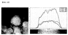
- a structure of the metal chalcogenide nanoparticles namely, a distribution type of the first phase and second phase, which is not specifically limited, may be a type wherein the first phase and second phase are evenly distributed, as illustrated in FIGS. 13 to 15 .
- the first phase and second phase may exist in a bulk type and thereby may form a complex.
- the metal chalcogenide nanoparticles may have a core-shell structure in which the first phase forms a core and the second phase forms a shell.
- composition ratio of metal in the metal chalcogenide nanoparticles in the observed area may be determined in a range of 0.5 ⁇ Cu/(Zn+Sn) ⁇ 1.5 and 0.5 ⁇ Zn/Sn ⁇ 2.0, particularly may be determined in a range of 0.7 ⁇ Cu/(Zn+Sn) ⁇ 1.2 and 0.8 ⁇ Zn/Sn ⁇ 1.4.
- the diameter of the core may be 5 nanometers to 200 nanometers and the thickness of the shell may be 1 nanometer to 100 nanometers in a range corresponding to the volume of the first phase and second phase occupying the nanoparticles, considering the diameter of the core.
- a composition ratio of the first phase and second phase occupying in a total of the metal chalcogenide nanoparticles may be determined in a range of 0.5 ⁇ Cu/(Zn+Sn) ⁇ 1.5 and 0.5 ⁇ Zn/Sn ⁇ 2.0, particularly may be determined in a range of 0.7 ⁇ Cu/(Zn+Sn) ⁇ 1.2 and 0.8 ⁇ Zn/Sn ⁇ 1.4.
- the metal chalcogenide nanoparticles may include 0.5 mol to 3 mol of a chalcogenide element based on 1 mol of a metal element.
- the metal element indicates all metal types.
- the method of preparing metal chalcogenide nanoparticles according to the present invention is performed by a solution process instead of a conventional vacuum process and thereby process costs may be dramatically reduced.
- a solvent to prepare a solution harmful hydrazine is not used and thereby a risk which may occur in a conventional solution process may be removed.
- a Group VI source may be further added.
- the Group VI source is included in an amount of 0.5 mol to 3 mol based on 1 mol of a metal element. If the first solution includes a sufficient amount of the Group VI source, an additional Group VI source is not required when the third solution is mixed. However, when the first solution does not include a sufficient amount of the Group VI source, a Group VI source may be further added to solve partial deficiency of a Group VI element. Here, the Group VI source may be added considering the amount of a Group VI element existing in a reaction product of the first solution and the second solution.
- the copper (Cu) salt, tin (Sn) salt and zinc (Zn) salt each independently may be at least one salt selected from the group consisting of a chloride, a bromide, an iodide, a nitrate, a nitrite, a sulfate, an acetate, a sulfite, an acetylacetonate and a hydroxide.
- tin (Sn) salt a divalent or tetravalent salt may be used, but embodiments of the present invention are not limited thereto.
- the Group VI source may be at least one salt selected from the group consisting of Se, Na 2 Se, K 2 Se, CaSe, (CH 3 ) 2 Se, SeO 2 SeCl 4 , H 2 SeO 3 , H 2 SeO 4 , Na 2 S, K 2 S, CaS, (CH 3 ) 2 S, H 2 SO 4 , S, Na 2 S 2 O 3 and NH 2 SO 3 H, and hydrates thereof, thiourea, thioacetamide, selenoacetamide and selenourea.
- the first solution to third solution may further comprise a capping agent.
- the capping agent is included during a solution process and thereby the size and particle phase of synthesized metal chalcogenide nanoparticles may be controlled.
- the capping agent includes atoms such as N, O, S and the like, and thereby the capping agent easily binds to surfaces of metal chalcogenide nanoparticles through lone pair electrons of the atoms and surrounds the surfaces. Accordingly, oxidization of the metal chalcogenide nanoparticles may be prevented.
- the capping agent is not particularly limited and may, for example, be at least one selected from the group consisting of polyvinylpyrrolidone, sodium L-tartrate dibasic dehydrate, potassium sodium tartrate, sodium mesoxalate, sodium acrylate, poly(acrylic acid sodium salt), poly(vinyl pyrrolidone), sodium citrate, trisodium citrate, disodium citrate, sodium gluconate, sodium ascorbate, sorbitol, triethyl phosphate, ethylene diamine, propylene diamine, 1,2-ethanedithiol, and ethanethiol.
- the method of preparing the thin film according to the present invention includes:
- the alcohols may be at least one mixed solvent selected from among ethanol, 1-propanol, 2-propanol, 1-pentanol, 2-pentanol, 1-hexanol, 2-hexanol, 3-hexanol, heptanol, octanol, ethylene glycol (EG), diethylene glycol monoethyl ether (DEGMEE), ethylene glycol monomethyl ether (EGMME), ethylene glycol monoethyl ether (EGMEE), ethylene glycol dimethyl ether (EGDME), ethylene glycol diethyl ether (EGDEE), ethylene glycol monopropyl ether (EGMPE), ethylene glycol monobutyl ether (EGMBE), 2-methyl-1-propanol, cyclopentanol, cyclohexanol, propylene glycol propyl ether (PGPE), diethylene glycol dimethyl ether (DEGDME), 1,2-propanediol (1,
- the amines may be at least one mixed solvent selected from among triethyl amine, dibutyl amine, dipropyl amine, butylamine, ethanolamine, diethylenetriamine (DETA), triethylenetetramine (TETA), triethanolamine, 2-aminoethyl piperazine, 2-hydroxyethyl piperazine, dibutylamine, and tris(2-aminoethyl)amine.
- mixed solvent selected from among triethyl amine, dibutyl amine, dipropyl amine, butylamine, ethanolamine, diethylenetriamine (DETA), triethylenetetramine (TETA), triethanolamine, 2-aminoethyl piperazine, 2-hydroxyethyl piperazine, dibutylamine, and tris(2-aminoethyl)amine.
- the thiols may be at least one mixed solvent selected from among 1,2-ethanedithiol, pentanethiol, hexanethiol, and mercaptoethanol.
- the alkanes may be at least one mixed solvent selected from among hexane, heptane, and octane.
- the aromatics may be at least one mixed solvent selected from among toluene, xylene, nitrobenzene, and pyridine.
- the organic halides may be at least one mixed solvent selected from among chloroform, methylene chloride, tetrachloromethane, dichloroethane, and chlorobenzene.
- the nitriles may be acetonitrile.
- the ethers may be at least one mixed solvent selected from among ethyl ether, tetrahydrofuran, and 1,4-dioxane.
- the sulfoxides may be at least one mixed solvent selected from among dimethyl sulfoxide (DMSO) and sulfolane.
- DMSO dimethyl sulfoxide
- the amides may be at least one mixed solvent selected from among dimethyl formamide (DMF) and n-methyl-2-pyrrolidone (NMP).
- DMF dimethyl formamide
- NMP n-methyl-2-pyrrolidone
- the esters may be at least one mixed solvent selected from among ethyl lactate, ⁇ -butyrolactone, and ethyl acetoacetate.
- the carboxylic acids may be at least one mixed solvent selected from among propionic acid, hexanoic acid, meso-2,3-dimercaptosuccinic acid, thiolactic acid, and thioglycolic acid.
- the ink in preparation of the ink, may be prepared by further adding an additive.
- the additive may, for example, be at least one selected from the group consisting of a dispersant, a surfactant, a polymer, a binder, a crosslinking agent, an emulsifying agent, an anti-foaming agent, a drying agent, a filler, a bulking agent, a thickening agent, a film conditioning agent, an antioxidant, a fluidizer, a leveling agent, and a corrosion inhibitor.
- the additive may be at least one selected from the group consisting of polyvinylpyrrolidone (PVP), polyvinyl alcohol, Anti-terra 204, Anti-terra 205, ethyl cellulose, and DispersBYK110.
- a method of forming a coating layer by coating the ink may, for example, be any one selected from the group consisting of wet coating, spray coating, spin-coating, doctor blade coating, contact printing, top feed reverse printing, bottom feed reverse printing, nozzle feed reverse printing, gravure printing, micro gravure printing, reverse micro gravure printing, roller coating, slot die coating, capillary coating, inkjet-printing, jet deposition, and spray deposition.
- step (iii) may be carried out at a temperature of 400 to 900 °C.
- a selenization process may be included to prepare the thin film of a solar cell having much higher density.
- the selenization process may be carried out through a variety of methods.
- effects obtained from the selenization process may be achieved by preparing an ink by dispersing S and/or Se in a particle type in a solvent with metal chalcogenide nanoparticles in step (i), and by combining the heat treatment of step (iii).
- effects obtained from the selenization process may be achieved through the heat treatment of step (iii) in the presence of S or Se
- S or Se may be present by supplying H 2 S or H 2 Se in a gaseous state or supplying Se or S in a gaseous state through heating.
- step (ii) S or Se may be deposited on the coated base, following by performing step (iii).
- the deposition process may be performed by a solution process or a deposition method.
- the present invention also provides a thin film prepared using the above-described method.
- a method of manufacturing a thin film solar cell is known in the art and thus a detailed description thereof will be omitted herein.
- cupric acetylacetonate Cu(acac) 2
- zinc acetate Zn(OAc) 2
- Sn(acac) 2 Br 2 Sn(acac) 2 Br 2
- temperature was elevated upto 225°C.
- the Cu 2 SnS 3 -ZnS prepared according to Example 8 was dispersed in a mixture of alcohol-based solvents to prepare an ink. Subsequently, the ink was coated onto a glass substrate coated with molybdenum (Mo) to form a coating film and then the coating film was dried. Subsequently, the coating film was heated with a glass substrate deposited with Se to provide a Se atmosphere and then subjected to rapid thermal annealing (RTA) at 575°C, resulting in a CZTSSe-based thin film. An SEM image and XRD graph of the obtained thin film are illustrated in FIGS. 6 and 7 , respectively.
- RTA rapid thermal annealing
- the CZTS nanoparticles prepared according to Comparative Example 1 were dispersed in toluene as a solvent to prepare an ink, and the ink was coated onto a soda lime glass substrate coated with Mo to form a coating film. Subsequently, the coating film was dried and then subjected to heat treatment at 450°C in a Se atmosphere, resulting in a CZTSSe-based thin film.
- An XRD graph of the obtained thin film is illustrated in FIG. 8 .
- the Cu 2 SnS 3 nanoparticles and ZnS nanoparticles prepared according to Comparative Example 2 were dispersed in a mixture of alcohol-based solvents to prepare an ink. Subsequently, the ink was coated onto a glass substrate coated with molybdenum (Mo) to form a coating film and then the coating film was dried. Subsequently, the coating film was heated with a glass substrate deposited with Se to provide an Se atmosphere and then subjected to rapid thermal annealing (RTA) at 575°C, resulting in a CZTSSe-based thin film. An XRD graph of the obtained thin film is illustrated in FIG 9 .
- RTA rapid thermal annealing
- the CZTSSe-based thin film prepared according to Example 17 was etched using a potassium cyanide (KCN) solution, a CdS layer having a thickness of 50 nm was formed thereon by chemical bath deposition (CBD), and a ZnO layer having a thickness of 100 nm and an Al-doped ZnO layer having a thickness of 500 nm were sequentially stacked thereon by sputtering, thereby completing preparation of a thin film. Subsequently, an A1 electrode was formed at the thin film, thereby completing manufacture of a thin film solar cell. A graph showing current-voltage (I-V) characteristics of the thin film solar cell is illustrated in FIG. 10 .
- KCN potassium cyanide
- CBD chemical bath deposition
- ZnO layer having a thickness of 100 nm and an Al-doped ZnO layer having a thickness of 500 nm were sequentially stacked thereon by sputtering, thereby completing preparation of a thin film.
- a CdS layer was formed on the CZTSSe-based thin film prepared according to Comparative Example 3 by chemical bath deposition (CBD) and then a ZnO layer and an ITO layer were sequentially stacked thereon by sputtering, thereby completing preparation of a thin film solar cell.
- CBD chemical bath deposition
- I-V current-voltage
- a CdS layer was mounted on the CZTSSe-based thin film prepared according to Comparative Example 4 by chemical bath deposition (CBD) and then a ZnO layer and an ITO layer were sequentially stacked thereon by sputtering, thereby completing preparation of a thin film solar cell.
- CBD chemical bath deposition
- I-V current-voltage
- J sc which is a variable determining the efficiency of each solar cell, represents current density
- V oc denotes an open circuit voltage measured at zero output current
- the photoelectric efficiency means a rate of cell output according to irradiance of light incident upon a solar cell plate
- fill factor (FF) represents a value obtained by dividing the product of current density and voltage values at maximum power by the product of Voc and J sc .
- the metal chalcogenide nanoparticles prepared according to the present invention were used in light absorption layer formation, the light absorption layer showed superior photoelectric efficiency due to high current density and voltage, when compared with metal chalcogenide nanoparticles prepared according to a prior method.
- metal chalcogenide nanoparticles according to the present invention include a first phase including copper (Cu)-tin (Sn) chalcogenide and a second phase including zinc (Zn) chalcogenide in one particle. Therefore, when a thin film is prepared using the metal chalcogenide nanoparticles, generation of a second phase may be suppressed, and the thin film may have an entirely uniform composition since one particle includes all of the metals.
- nanoparticles include S or Se, the nanoparticles are stable against oxidation and the amount of a Group VI element in a final thin layer may be increased. Furthermore, the volumes of particles are extended in a selenization process due to addition of a Group VI element and thereby a light absorption layer having higher density may be grown.
- metal chalcogenide nanoparticles according to the present invention are prepared through a solution process, process costs may be dramatically reduced, when compared with conventional processes. Furthermore, a harmful reducing agent such as hydrazine is not used and, as such, risk due to use of the reducing harmful agent may be removed.
Landscapes
- Photovoltaic Devices (AREA)
- Luminescent Compositions (AREA)
- Life Sciences & Earth Sciences (AREA)
- Engineering & Computer Science (AREA)
- Sustainable Development (AREA)
- Sustainable Energy (AREA)
- Manufacture Of Metal Powder And Suspensions Thereof (AREA)
- Inorganic Compounds Of Heavy Metals (AREA)
- Paints Or Removers (AREA)
- Inks, Pencil-Leads, Or Crayons (AREA)
Abstract
Description
- The present invention relates to metal chalcogenide nanoparticles for preparing a light absorption layer of solar cells and a method of preparing the same.
- Solar cells have been manufactured using a light absorption layer formed at high cost and silicon (Si) as a semiconductor material since an early stage of development. To more economically manufacture commercially viable solar cells, structures of thin film solar cells, using an inexpensive light absorbing material such as copper indium gallium sulfo (di) selenide (CIGS) or Cu(In, Ga)(S, Se)2, have been developed. Such CIGS-based solar cells typically include a rear electrode layer, an n-type junction part, and a p-type light absorption layer. Solar cells including such CIGS layers have a power conversion efficiency of greater than 19%. However, in spite of potential for CIGS-based thin film solar cells, costs and insufficient supply of In are main obstacles to widespread commercial application of thin film solar cells using CIGS-based light absorption layers. Thus, there is an urgent need to develop solar cells using In-free or low-cost universal elements.
- Accordingly, as an alternative to the CIGS-based light absorption layer, CZTS(Cu2ZnSn(S,Se)4)-based solar cells including copper (Cu), zinc (Zn), tin (Sn), sulfur (S), or selenium (Se), which are extremely cheap elements, have recently received attention. CZTS has a direct band gap of about 1.0 eV to about 1.5 eV and an absorption coefficient of 104 cm-1 or more, reserves thereof are relatively high, and CZTS uses Sn and Zn, which are inexpensive.
- In 1996, CZTS hetero-junction PV batteries were reported for the first time, but CZTS-based solar cells have less advanced less than CIGS-based solar cells and photoelectric efficiency of CZTS-based solar cells is 10% or less, much lower than that of CIGS-based solar cells. Thin films of CZTS are prepared by sputtering, hybrid sputtering, pulsed laser deposition, spray pyrolysis, electro-deposition/thermal sulfurization, e-beam processing, Cu/Zn/Sn/thermal sulfurization, and a sol-gel method.
- Meanwhile,
PCT/US/2010-035792 discloses formation of a thin film through heat treatment of ink including CZTS/Se nanoparticles on a base. Generally, when a CZTS thin film is formed with CZTS/Se nanoparticles, it is difficult to enlarge crystal size at a forming process of a thin film due to previously formed small crystals. As such, when each grain is small, interfaces are extended and thereby electron loss occurs at interfaces, and, accordingly, efficiency is deteriorated. - Accordingly, nanoparticles used in a thin film must include Cu, Zn and Sn, and must not be a CZTS crystal type. However, metal nanoparticles constituted of a single metal element may be easily oxidized and, at a subsequent process, an oxygen removal process using a large amount of Se and high temperature is required. In addition, when a chalcogenide including each metal is synthesized respectively and mixed, a nonuniform metal composition ratio may raise a problem. Therefore, there is a high need to develop a technology for thin film solar cells including highly efficient light absorption layers that are stable against oxidation and drawbacks of which are minimized due to a homogenous composition.
- Therefore, the present invention has been made to solve the above and other technical problems that have yet to be resolved.
- As a result of a variety of intensive studies and various experiments, the inventors of the present invention developed metal chalcogenide nanoparticles including a first phase including copper (Cu)-tin (Sn) chalcogenide and a second phase including zinc (Zn) chalcogenide, and confirmed that, when a thin film was prepared using the metal chalcogenide nanoparticles, generation of a second phase in the thin film may be suppressed, the thin film had an entirely uniform composition and was stable against oxidation by adding S or Se to the nanoparticles, and the amount of a Group VI element in a final thin film was increased, resulting in a superior quality thin film and thus completing the present invention.
- In accordance with one aspect of the present invention, provided are metal chalcogenide nanoparticles forming light absorption layers of solar cells including a first phase including copper (Cu)-tin (Sn) chalcogenide and a second phase including zinc (Zn) chalcogenide.
- The term "chalcogenide" of the present invention means a material including a Group VI element, for example, sulfur (S) or selenium (Se). As one embodiment, the copper (Cu)-tin (Sn) chalcogenide may be CuaSnSb (1.2≤a≤3.2 and 2.5≤b≤4.5), and/or CuxSnSey (1.2≤x≤3.2, 2.5≤y≤4.5), the zinc (Zn)-containing chalcogenide may be ZnS and/or ZnSe.
- The two phases constituting the metal chalcogenide nanoparticles independently exist in one metal chalcogenide nanoparticle and a composition ratio of the metal in the metal chalcogenide nanoparticles may be in a range of 0.5≤Cu/(Zn+Sn)≤1.5 and 0.5≤Zn/Sn≤2.0, particularly in a range of 0.7≤Cu/(Zn+Sn)≤1.2 and 0.8≤Zn/Sn≤1.4.
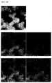
- A structure of the metal chalcogenide nanoparticles, namely, a distribution type of the first phase and second phase, which is not specifically limited, may be a type wherein the first phase and second phase are evenly distributed, as illustrated in
FIGS. 13 to 15 . The first phase and second phase may exist in a bulk type and thereby may form a complex. Alternatively, the metal chalcogenide nanoparticles may have a core-shell structure in which the first phase forms a core and the second phase forms a shell. - If the metal chalcogenide nanoparticles are evenly distributed, when a certain area in the metal chalcogenide was observed using SEM-EDX or TEM-EDX, composition ratio of metal in the metal chalcogenide nanoparticles in the observed area may be determined in a range of 0.5≤Cu/(Zn+Sn)≤1.5 and 0.5≤Zn/Sn≤2.0, particularly may be determined in a range of 0.7≤Cu/(Zn+Sn)≤1.2 and 0.8≤Zn/Sn≤1.4.
- When the metal chalcogenide nanoparticles have a core-shell structure, the diameter of the core may be 5 nanometers to 200 nanometers and the thickness of the shell may be 1 nanometer to 100 nanometers in a range corresponding to the volume of the first phase and second phase occupying the nanoparticles, considering the diameter of the core.
- Outside the range, when the size of the core is too large, the metal chalcogenide nanoparticles formed into the shell are too large and thereby pores among particles in a final thin film having a thickness of 1 micrometer to 2 micrometers are enlarged. On the other hand, when the size of the core is too small, particles may be easily aggregated. In addition, to provide the final thin film having a proper composition ratio, the thickness of the shell becomes extremely thin and thereby, it is difficult to form the shell to a proper thickness.
- Meanwhile, regardless of the shape, a composition ratio of the first phase and second phase occupying in a total of the metal chalcogenide nanoparticles may be determined in a range of 0.5≤Cu/(Zn+Sn)≤1.5 and 0.5≤Zn/Sn≤2.0, particularly may be determined in a range of 0.7≤Cu/(Zn+Sn)≤1.2 and 0.8≤Zn/Sn≤1.4.
- As a specific embodiment, the metal chalcogenide nanoparticles may include 0.5 mol to 3 mol of a chalcogenide element based on 1 mol of a metal element. Here, the metal element indicates all metal types.
- Outside the above range, when too much of the metal element is included, sufficient supply of a Group VI element is impossible and thereby stable phases such as the above metal chalcogenide are not formed and, accordingly, in subsequent processes, phases may be changed and form a second phase or separated metals may be oxidized. On the contrary, when too much of the chalcogenide element is included, a Group VI source is evaporated during a heat treatment process for preparing a thin film and thereby a final thin film may have too many pores.
- The present invention also provides a method of synthesizing the metal chalcogenide nanoparticles. The method may particularly include:
- (i) preparing a first solution including at least one a Group VI source selected from the group consisting of a compound including (i) sulfur (S) or selenium (Se);
- (ii) preparing a second solution including a copper (Cu) salt and tin (Sn) salt and a third solution including a zinc (Zn) salt;
- (iii) mixing and reacting the first solution and second solution; and
- (iv) mixing and reacting the third solution with a reaction product of the mixing and reacting.
- That is, the method of preparing metal chalcogenide nanoparticles according to the present invention is performed by a solution process instead of a conventional vacuum process and thereby process costs may be dramatically reduced. In addition, as a solvent to prepare a solution, harmful hydrazine is not used and thereby a risk which may occur in a conventional solution process may be removed.
- As a specific embodiment, when the third solution of step (iv) is mixed, a Group VI source may be further added.
- As described above, the Group VI source is included in an amount of 0.5 mol to 3 mol based on 1 mol of a metal element. If the first solution includes a sufficient amount of the Group VI source, an additional Group VI source is not required when the third solution is mixed. However, when the first solution does not include a sufficient amount of the Group VI source, a Group VI source may be further added to solve partial deficiency of a Group VI element. Here, the Group VI source may be added considering the amount of a Group VI element existing in a reaction product of the first solution and the second solution.
- In a specific embodiment, solvents for the first solution, second solution and third solution may be at least one selected from the group consisting of water, alcohols, diethylene glycol (DEG), oleylamine, ethylene glycol, triethylene glycol, dimethyl sulfoxide, dimethyl formamide, and N-methyl-2-pyrrolidone (NMP). In particular, the alcohol solvents may be methanol, ethanol, propanol, butanol, pentanol, hexanol, heptanol and octanol having 1 to 8 carbons.
- In a specific embodiment, the copper (Cu) salt, tin (Sn) salt and zinc (Zn) salt each independently may be at least one salt selected from the group consisting of a chloride, a bromide, an iodide, a nitrate, a nitrite, a sulfate, an acetate, a sulfite, an acetylacetonate and a hydroxide. As the tin (Sn) salt, a divalent or tetravalent salt may be used, but embodiments of the present invention are not limited thereto.
- In a specific embodiment, the Group VI source may be at least one salt selected from the group consisting of Se, Na2Se, K2Se, CaSe, (CH3)2Se, SeO2 SeCl4, H2SeO3, H2SeO4, Na2S, K2S, CaS, (CH3)2S, H2SO4, S, Na2S2O3 and NH2SO3H, and hydrates thereof, thiourea, thioacetamide, selenoacetamide and selenourea.
- Meanwhile, the first solution to third solution may further comprise a capping agent.
- The capping agent is included during a solution process and thereby the size and particle phase of synthesized metal chalcogenide nanoparticles may be controlled. In addition, the capping agent includes atoms such as N, O, S and the like, and thereby the capping agent easily binds to surfaces of metal chalcogenide nanoparticles through lone pair electrons of the atoms and surrounds the surfaces. Accordingly, oxidization of the metal chalcogenide nanoparticles may be prevented.
- The capping agent is not particularly limited and may, for example, be at least one selected from the group consisting of polyvinylpyrrolidone, sodium L-tartrate dibasic dehydrate, potassium sodium tartrate, sodium mesoxalate, sodium acrylate, poly(acrylic acid sodium salt), poly(vinyl pyrrolidone), sodium citrate, trisodium citrate, disodium citrate, sodium gluconate, sodium ascorbate, sorbitol, triethyl phosphate, ethylene diamine, propylene diamine, 1,2-ethanedithiol, and ethanethiol.
- The present invention also provides an ink composition for preparing light absorption layers including the metal chalcogenide nanoparticles and a method of preparing a thin film using the ink composition.
- The method of preparing the thin film according to the present invention includes:
- (i) dispersing metal chalcogenide nanoparticles including a first phase including copper (Cu)-tin (Sn) chalcogenide and a second phase including zinc (Zn) chalcogenide in a solvent to prepare an ink;
- (ii) coating the ink on a base provided with an electrode; and
- (iii) drying and then heat-treating the ink coated on the base provided with an electrode.
- In a specific embodiment, the solvent of step (i) is not particularly limited so long as the solvent is a general organic solvent and may be one organic solvent selected from among alkanes, alkenes, alkynes, aromatics, ketones, nitriles, ethers, esters, organic halides, alcohols, amines, thiols, carboxylic acids, phosphines, phosphites, phosphates, sulfoxides, and amides or a mixture of at least one organic solvent selected therefrom.
- In particular, the alcohols may be at least one mixed solvent selected from among ethanol, 1-propanol, 2-propanol, 1-pentanol, 2-pentanol, 1-hexanol, 2-hexanol, 3-hexanol, heptanol, octanol, ethylene glycol (EG), diethylene glycol monoethyl ether (DEGMEE), ethylene glycol monomethyl ether (EGMME), ethylene glycol monoethyl ether (EGMEE), ethylene glycol dimethyl ether (EGDME), ethylene glycol diethyl ether (EGDEE), ethylene glycol monopropyl ether (EGMPE), ethylene glycol monobutyl ether (EGMBE), 2-methyl-1-propanol, cyclopentanol, cyclohexanol, propylene glycol propyl ether (PGPE), diethylene glycol dimethyl ether (DEGDME), 1,2-propanediol (1,2-PD), 1,3-propanediol (1,3-PD), 1,4-butanediol (1,4-BD), 1,3-butanediol (1,3-BD), α-terpineol, diethylene glycol (DEG), glycerol, 2-(ethylamino)ethanol, 2-(methylamino)ethanol, and 2-amino-2-methyl-1-propanol.
- The amines may be at least one mixed solvent selected from among triethyl amine, dibutyl amine, dipropyl amine, butylamine, ethanolamine, diethylenetriamine (DETA), triethylenetetramine (TETA), triethanolamine, 2-aminoethyl piperazine, 2-hydroxyethyl piperazine, dibutylamine, and tris(2-aminoethyl)amine.
- The thiols may be at least one mixed solvent selected from among 1,2-ethanedithiol, pentanethiol, hexanethiol, and mercaptoethanol.
- The alkanes may be at least one mixed solvent selected from among hexane, heptane, and octane.
- The aromatics may be at least one mixed solvent selected from among toluene, xylene, nitrobenzene, and pyridine.
- The organic halides may be at least one mixed solvent selected from among chloroform, methylene chloride, tetrachloromethane, dichloroethane, and chlorobenzene.
- The nitriles may be acetonitrile.
- The ketones may be at least one mixed solvent selected from among acetone, cyclohexanone, cyclopentanone, and acetyl acetone.
- The ethers may be at least one mixed solvent selected from among ethyl ether, tetrahydrofuran, and 1,4-dioxane.
- The sulfoxides may be at least one mixed solvent selected from among dimethyl sulfoxide (DMSO) and sulfolane.
- The amides may be at least one mixed solvent selected from among dimethyl formamide (DMF) and n-methyl-2-pyrrolidone (NMP).
- The esters may be at least one mixed solvent selected from among ethyl lactate, γ-butyrolactone, and ethyl acetoacetate.
- The carboxylic acids may be at least one mixed solvent selected from among propionic acid, hexanoic acid, meso-2,3-dimercaptosuccinic acid, thiolactic acid, and thioglycolic acid.
- However, the solvents are only given as an example, and embodiments of the present invention are not limited thereto.
- In some cases, in preparation of the ink, the ink may be prepared by further adding an additive.
- The additive may, for example, be at least one selected from the group consisting of a dispersant, a surfactant, a polymer, a binder, a crosslinking agent, an emulsifying agent, an anti-foaming agent, a drying agent, a filler, a bulking agent, a thickening agent, a film conditioning agent, an antioxidant, a fluidizer, a leveling agent, and a corrosion inhibitor. In particular, the additive may be at least one selected from the group consisting of polyvinylpyrrolidone (PVP), polyvinyl alcohol, Anti-terra 204, Anti-terra 205, ethyl cellulose, and DispersBYK110.
- A method of forming a coating layer by coating the ink may, for example, be any one selected from the group consisting of wet coating, spray coating, spin-coating, doctor blade coating, contact printing, top feed reverse printing, bottom feed reverse printing, nozzle feed reverse printing, gravure printing, micro gravure printing, reverse micro gravure printing, roller coating, slot die coating, capillary coating, inkjet-printing, jet deposition, and spray deposition.
- The heat treatment of step (iii) may be carried out at a temperature of 400 to 900 °C.
- Meanwhile, a selenization process may be included to prepare the thin film of a solar cell having much higher density. The selenization process may be carried out through a variety of methods.
- As a first example, effects obtained from the selenization process may be achieved by preparing an ink by dispersing S and/or Se in a particle type in a solvent with metal chalcogenide nanoparticles in step (i), and by combining the heat treatment of step (iii).
- As a second example, effects obtained from the selenization process may be achieved through the heat treatment of step (iii) in the presence of S or Se
- In particular, S or Se may be present by supplying H2S or H2Se in a gaseous state or supplying Se or S in a gaseous state through heating.
- As a third example, after step (ii), S or Se may be deposited on the coated base, following by performing step (iii). In particular, the deposition process may be performed by a solution process or a deposition method.
- The present invention also provides a thin film prepared using the above-described method.
- The thin film may have a thickness of 0.5 µm to 3.0 µm, more particularly 0.5 µm to 2.5 µm.
- When the thickness of the thin film is less than 0.5 µm, the density and amount of the light absorption layer are insufficient and thus desired photoelectric efficiency may not be obtained. On the other hand, when the thickness of the thin film exceeds 3.0 µm, movement distances of carriers increase and, accordingly, there is an increased probability of recombination, which results in reduced efficiency.
- The present invention also provides a thin film solar cell manufactured using the thin film.
- A method of manufacturing a thin film solar cell is known in the art and thus a detailed description thereof will be omitted herein.
- The above and other objects, features and other advantages of the present invention will be more clearly understood from the following detailed description taken in conjunction with the accompanying drawing, in which:
-
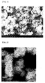
FIG. 1 is an SEM image of Cu2SnS3-ZnS nanoparticles formed according to Example 1; -
FIG. 2 is a TEM image of Cu2SnS3-ZnS nanoparticles formed according to Example 1; -
FIG. 3 is an XRD graph of Cu2SnS3-ZnS nanoparticles formed according to Example 1; -
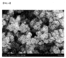
FIG. 4 is an SEM image of Cu2SnS3-ZnS nanoparticles formed according to Example 1; -
FIG. 5 is an XRD graph of Cu2SnS3-ZnS nanoparticles formed according to Example 1; -
FIG. 6 is an SEM image of a thin film prepared according to Example 17 ; -
FIG. 7 is an XRD graph of a thin film prepared according to Example 17; -
FIG. 8 is an XRD graph of a thin film prepared according to Comparative Example 3; -
FIG. 9 is an XRD graph of a thin film prepared according to Comparative Example 4; -
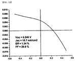
FIG. 10 is an IV characteristic graph of a thin film solar cell prepared according to Example 18; -
FIG. 11 is an IV characteristic graph of a thin film solar cell manufactured according to Comparative Example 5; -
FIG. 12 is an IV characteristic graph of a thin film solar cell manufactured according to Comparative Example 6; -
FIG. 13 is a table illustrating SEM-EDX results of Cu2SnS3-ZnS nanoparticles demonstrating even particle distribution in particles synthesized according to the present invention; -
FIG. 14 is an EDS mapping result of Cu2SnS3-ZnS nanoparticles demonstrating even metal distribution in particles synthesized according to the present invention; and -
FIG. 15 is a line-scan result of a Cu2SnS3-ZnS nanoparticle composition demonstrating even metal distribution in particles synthesized according to the present invention. - Now, the present invention will be described in more detail with reference to the following examples. These examples are provided only for illustration of the present invention and should not be construed as limiting the scope and spirit of the present invention.
- After adding a DEG solution including 30 mmol of thioacetamide to a DEG solution including 10 mmol of CuCl2 and a DEG solution including 5 mmol of SnCl2, temperature was elevated to 175°C and then the solution was reacted while stirring for three hours. Subsequently, a DEG solution including 7 mmol of ZnCl2 was slowly added to the reacted solution dropwise at room temperature. Subsequently, the solution was heated to 180°C or more and then, maintaining the temperature, stirred for three hours. Subsequently, the solution was purified through centrifugation, resulting in Cu2SnS3-ZnS nanoparticles. A scanning electron microscope (SEM) image, a transmission electron microscope (TEM) image and an XRD graph of the formed particles are illustrated in
FIGS. 1 to 3 . - After adding a DEG solution including 30 mmol of thioacetamide to a DEG solution including 10 mmol of CuSO4 and a DEG solution including 5 mmol of SnCl2, temperature was elevated to 175°C and then the solution was reacted while stirring for three hours. Subsequently, a DEG solution including 7 mmol of ZnCl2 was slowly added to the reacted solution dropwise at room temperature. Subsequently, the solution was heated to 180°C or more and then, maintaining the temperature, stirred for three hours. Subsequently, the solution was purified through centrifugation, resulting in Cu2SnS3-ZnS nanoparticles.
- After adding a DEG solution including 30 mmol of thioacetamide to a DEG solution including 10 mmol of CuSO4 and a DEG solution including 5 mmol of Sn(OAc)2, temperature was elevated to 175°C and then the solution was reacted while stirring for three hours. Subsequently, a DEG solution including 7 mmol of ZnCl2 was slowly added to the reacted solution dropwise at room temperature. Subsequently, the solution was heated to 180°C or more and then, maintaining the temperature, stirred for three hours. Subsequently, the solution was purified through centrifugation, resulting in Cu2SnS3-ZnS nanoparticles.
- After adding a DEG solution including 30 mmol of thiourea to a DEG solution including 10 mmol of CuCl2 and a DEG solution including 5 mmol of SnCl2, temperature was elevated to 175°C and then the solution was reacted while stirring for three hours. Subsequently, a DEG solution including 7 mmol of ZnCl2 was slowly added to the reacted solution dropwise at room temperature. Subsequently, the solution was heated to 180°C or more and then, maintaining the temperature, stirred for three hours. Subsequently, the solution was purified through centrifugation, resulting in Cu2SnS3-ZnS nanoparticles.
- After adding a DEG solution including 15 mmol of thioacetamide to a DEG solution including 10 mmol of CuCl2 and a DEG solution including 5 mmol of SnCl2, temperature was elevated to 175°C and then the solution was reacted while stirring for five hours. Subsequently, a DEG solution including 6 mmol of ZnCl2 and a DEG solution including 6 mmol of thioacetamide were slowly added to the reacted solution dropwise at room temperature. Subsequently, the solution was heated to 180°C or more and then, maintaining the temperature, stirred for three hours. Subsequently, the solution was purified through centrifugation, resulting in Cu2SnS3-ZnS nanoparticles.
- After adding a DEG solution including 20 mmol of thioacetamide to a DEG solution including 10 mmol of CuCl2 and a DEG solution including 5 mmol of SnCl2, temperature was elevated to 175°C and then the solution was reacted while stirring for three hours. Subsequently, a DEG solution including 6 mmol of ZnCl2 and a DEG solution including 12 mmol of thioacetamide were slowly added to the reacted solution dropwise at room temperature. Subsequently, the solution was heated to 180°C or more and then, maintaining the temperature, stirred for three hours. Subsequently, the solution was purified through centrifugation, resulting in Cu2SnS3-ZnS nanoparticles.
- After adding a DEG solution including 20 mmol of thioacetamide to a DEG solution including 10 mmol of CuCl2 and a DEG solution including 5 mmol of SnCl2, temperature was elevated to 175°C and then the solution was reacted while stirring for six hours. Subsequently, a DEG solution including 6 mmol of ZnCl2 and a DEG solution including 12 mmol of thioacetamide were slowly added to the reacted solution dropwise at room temperature. Subsequently, the solution was heated to 180°C or more and then, maintaining the temperature, stirred for three hours. Subsequently, the solution was purified through centrifugation, resulting in Cu2SnS3-ZnS nanoparticles. A scanning electron microscope (SEM) image and an XRD graph of the formed particles are illustrated in
FIGS. 4 and5 . - After adding an EG solution including 30 mmol of thioacetamide to an EG solution including 10 mmol of CuCl2 and an EG solution including 5 mmol of SnCl2, temperature was elevated to 175°C and then the solution was reacted while stirring for three hours. Subsequently, an EG solution including 6 mmol of ZnCl2 was slowly added to the reacted solution dropwise at room temperature. Subsequently, the solution was heated to 180°C or more and then, maintaining the temperature, stirred for three hours. Subsequently, the solution was purified through centrifugation, resulting in Cu2SnS3-ZnS nanoparticles.
- After adding a DEG solution including 30 mmol of thioacetamide to a DEG solution including 10 mmol of CuCl2, a DEG solution including 5 mmol of SnCl2 and a DEG solution including 1 mmol of PVP, temperature was elevated to 175°C and then the solution was reacted while stirring for three hours. Subsequently, an DEG solution including 7 mmol of ZnCl2 was slowly added to the reacted solution dropwise at room temperature. Subsequently, the solution was heated to 180°C or more and then, maintaining the temperature, stirred for three hours. Subsequently, the solution was purified through centrifugation, resulting in Cu2SnS3-ZnS nanoparticles.
- After adding an H2O solution including 30 mmol of thioacetamide to an H2O solution including 10 mmol of CuCl2 and an H2O solution including 5 mmol of SnCl2, temperature was elevated to 100°C and then reacted while stirring for three hours. Subsequently, an H2O solution including 6 mmol of ZnCl2 was slowly added to the reacted solution dropwise at room temperature and then temperature was elevated to 100°C. Maintaining the temperature, the solution was stirred for three hours and then purified through centrifugation, resulting in Cu2SnS3-ZnS nanoparticles.
- After adding an H2O solution including 30 mmol of thioacetamide to an H2O solution including 10 mmol of CuCl2, an H2O solution including 5 mmol of SnCl2 and an H2O solution including 10 mmol of sodium citrate, temperature was elevated to 100°C and then reacted while stirring for six hours. Subsequently, an H2O solution including 6 mmol of ZnCl2 and an H2O solution including 12 mmol of thioacetamide were slowly added to the reacted solution dropwise at room temperature and then temperature was elevated to 100°C. Maintaining the temperature, the solution was stirred for three hours and then purified through centrifugation, resulting in Cu2SnS3-ZnS nanoparticles.
- After adding an H2O solution including 30 mmol of thioacetamide to an H2O solution including 10 mmol of Cu(NO3)2, an H2O solution including 5 mmol of SnCl2 and an H2O solution including 10 mmol of sodium mesoxalate, temperature was elevated to 100°C and then reacted while stirring for six hours. Subsequently, an H2O solution including 6 mmol of Zn(OAc)2 and an H2O solution including 12 mmol of thioacetamide were slowly added to the reacted solution dropwise at room temperature and then temperature was elevated to 100°C. Maintaining the temperature, the solution was stirred for five hours and then purified through centrifugation, resulting in Cu2SnS3-ZnS nanoparticles.
- After adding an H2O solution including 30 mmol of Na2S to an H2O solution including 10 mmol of CuCl2 and an H2O solution including 5 mmol of SnCl2, the resulting solution was reacted while stirring for three hours at room temperature. Subsequently, an H2O solution including 6 mmol of ZnCl2 was slowly added to the reacted solution dropwise and then the resulting solution was stirred for three hours at room temperature. The resulting solution was purified through centrifugation, resulting in Cu2SnS3-ZnS nanoparticles.
- After adding an H2O solution including 30 mmol of Na2S to an H2O solution including 10 mmol of CuSO4, an H2O solution including 5 mmol of SnCl2 and an H2O solution including 15 mmol of sodium citrate, the resulting solution was reacted while stirring for three hours at room temperature. Subsequently, an H2O solution including 6 mmol of ZnCl2 was slowly added to the reacted solution dropwise and then the resulting solution was stirred for three hours at room temperature. The resulting solution was purified through centrifugation, resulting in Cu2SnS3-ZnS nanoparticles.
- After adding an H2O solution including 30 mmol of Na2S to an H2O solution including 10 mmol of CUSO4 and an H2O solution including 5 mmol of SnCl2, the resulting solution was reacted while stirring for three hours at room temperature. Subsequently, an H2O solution including 6 mmol of ZnCl2 was slowly added to the reacted solution dropwise and then the resulting solution was stirred for three hours at room temperature. The resulting solution was purified through centrifugation, resulting in Cu2SnS3-ZnS nanoparticles.
- After adding an H2O solution including 30 mmol of Na2S to an H2O solution including 10 mmol of Cu(NO3)2 and an H2O solution including 5 mmol of SnCl2, the solution was reacted while stirring for three hours at room temperature. Subsequently, an H2O solution including 6 mmol of ZnCl2 was slowly added to the reacted solution dropwise and then the resulting solution was stirred for three hours at room temperature. The resulting solution was purified through centrifugation, resulting in Cu2SnS3-ZnS nanoparticles
- After dissolving cupric acetylacetonate (Cu(acac)2), zinc acetate (Zn(OAc)2) and Sn(acac)2Br2 in an oleylamine solution, temperature was elevated upto 225°C. An oleylamine solution, in which S elements were dissolved, was further added thereto dropwise. Formed particles were purified through centrifugation, resulting in CZTS nanoparticles.
- After dissolving CuCl2·2H2O, SnCl2 and thioacetamide in a diethylene glycol solution, the resulting solution was heated to 175°C for 2.5 hours. Synthesized particles were purified through centrifugation, resulting in Cu2SnS3 particles. In addition, after separately dissolving ZnCl2, thioacetamide and PVP in a diethylene Glycol solution, the resulting solution was heated to 175°C for 2.5 hours. Synthesized particles were purified through centrifugation, resulting in ZnS particles.
- The Cu2SnS3-ZnS prepared according to Example 8 was dispersed in a mixture of alcohol-based solvents to prepare an ink. Subsequently, the ink was coated onto a glass substrate coated with molybdenum (Mo) to form a coating film and then the coating film was dried. Subsequently, the coating film was heated with a glass substrate deposited with Se to provide a Se atmosphere and then subjected to rapid thermal annealing (RTA) at 575°C, resulting in a CZTSSe-based thin film. An SEM image and XRD graph of the obtained thin film are illustrated in
FIGS. 6 and7 , respectively. - The CZTS nanoparticles prepared according to Comparative Example 1 were dispersed in toluene as a solvent to prepare an ink, and the ink was coated onto a soda lime glass substrate coated with Mo to form a coating film. Subsequently, the coating film was dried and then subjected to heat treatment at 450°C in a Se atmosphere, resulting in a CZTSSe-based thin film. An XRD graph of the obtained thin film is illustrated in
FIG. 8 . - The Cu2SnS3 nanoparticles and ZnS nanoparticles prepared according to Comparative Example 2 were dispersed in a mixture of alcohol-based solvents to prepare an ink. Subsequently, the ink was coated onto a glass substrate coated with molybdenum (Mo) to form a coating film and then the coating film was dried. Subsequently, the coating film was heated with a glass substrate deposited with Se to provide an Se atmosphere and then subjected to rapid thermal annealing (RTA) at 575°C, resulting in a CZTSSe-based thin film. An XRD graph of the obtained thin film is illustrated in
FIG 9 . - The CZTSSe-based thin film prepared according to Example 17 was etched using a potassium cyanide (KCN) solution, a CdS layer having a thickness of 50 nm was formed thereon by chemical bath deposition (CBD), and a ZnO layer having a thickness of 100 nm and an Al-doped ZnO layer having a thickness of 500 nm were sequentially stacked thereon by sputtering, thereby completing preparation of a thin film. Subsequently, an A1 electrode was formed at the thin film, thereby completing manufacture of a thin film solar cell. A graph showing current-voltage (I-V) characteristics of the thin film solar cell is illustrated in
FIG. 10 . - A CdS layer was formed on the CZTSSe-based thin film prepared according to Comparative Example 3 by chemical bath deposition (CBD) and then a ZnO layer and an ITO layer were sequentially stacked thereon by sputtering, thereby completing preparation of a thin film solar cell. A graph showing current-voltage (I-V) characteristics of the thin film solar cell is illustrated in
FIG. 10 . - A CdS layer was mounted on the CZTSSe-based thin film prepared according to Comparative Example 4 by chemical bath deposition (CBD) and then a ZnO layer and an ITO layer were sequentially stacked thereon by sputtering, thereby completing preparation of a thin film solar cell. A graph showing current-voltage (I-V) characteristics of the thin film solar cell is illustrated in
FIG. 12 . - Photoelectric efficiencies of the thin film solar cells of Example 18 and Comparative Examples 5 and 6 were measured and measurement results are shown in Table 2 below and
FIGS. 10 to 12 .[Table 1] Jsc (mA/cm2) Vos (V) FF Photoelectric efficiency (%) Example 18 18.7 0.240 0.299 1.34 Comparative Example 5 10.5 0.188 0.372 0.73 Comparative Example 6 9.1 0.171 0.371 0.58 - In Table 1, Jsc, which is a variable determining the efficiency of each solar cell, represents current density, Voc denotes an open circuit voltage measured at zero output current, the photoelectric efficiency means a rate of cell output according to irradiance of light incident upon a solar cell plate, and fill factor (FF) represents a value obtained by dividing the product of current density and voltage values at maximum power by the product of Voc and Jsc.
- As seen in Table 1 above, when the metal chalcogenide nanoparticles prepared according to the present invention were used in light absorption layer formation, the light absorption layer showed superior photoelectric efficiency due to high current density and voltage, when compared with metal chalcogenide nanoparticles prepared according to a prior method.
- Although the preferred embodiments of the present invention have been disclosed for illustrative purposes, those skilled in the art will appreciate that various modifications, additions and substitutions are possible, without departing from the scope and spirit of the invention as disclosed in the accompanying claims.
- As described above, metal chalcogenide nanoparticles according to the present invention include a first phase including copper (Cu)-tin (Sn) chalcogenide and a second phase including zinc (Zn) chalcogenide in one particle. Therefore, when a thin film is prepared using the metal chalcogenide nanoparticles, generation of a second phase may be suppressed, and the thin film may have an entirely uniform composition since one particle includes all of the metals. In addition, since nanoparticles include S or Se, the nanoparticles are stable against oxidation and the amount of a Group VI element in a final thin layer may be increased. Furthermore, the volumes of particles are extended in a selenization process due to addition of a Group VI element and thereby a light absorption layer having higher density may be grown.
- In addition, since the metal chalcogenide nanoparticles according to the present invention are prepared through a solution process, process costs may be dramatically reduced, when compared with conventional processes. Furthermore, a harmful reducing agent such as hydrazine is not used and, as such, risk due to use of the reducing harmful agent may be removed.
Claims (30)
- Metal chalcogenide nanoparticles forming a light absorption layer of solar cells comprising a first phase comprising copper (Cu)-tin (Sn) chalcogenide and a second phase comprising zinc (Zn) chalcogenide.
- The metal chalcogenide nanoparticles according to claim 1, wherein the copper (Cu)-tin (Sn) chalcogenide is CuaSnSb wherein 1.2≤a≤3.2 and 2.5≤b≤4.5, and/or CuxSnSey wherein 1.2≤x≤3.2 and 2.5≤y≤4.5.
- The metal chalcogenide nanoparticles according to claim 1, wherein the zinc (Zn) chalcogenide is ZnS and/or ZnSe.
- The metal chalcogenide nanoparticles according to claim 1, wherein the first phase and the second phase exist independently.
- The metal chalcogenide nanoparticles according to claim 1, wherein a composition ratio of a metal in the metal chalcogenide nanoparticles is determined in a range of 0.5≤Cu/(Zn+Sn)≤1.5 and 0.5≤Zn/Sn≤2.0.
- The metal chalcogenide nanoparticles according to claim 1, wherein the first phase and the second phase are evenly distributed in metal chalcogenide nanoparticles.
- The metal chalcogenide nanoparticles according to claim 6, wherein, when a certain area in the metal chalcogenide is observed, a composition ratio of a metal in metal chalcogenide nanoparticles in the area is determined in a range of 0.5≤Cu/(Zn+Sn)≤1.5 and 0.5≤Zn/Sn≤2.0.
- The metal chalcogenide nanoparticles according to claim 7, wherein a composition ratio of the metal in the metal chalcogenide nanoparticles in the area is determined in a range of 0.7≤Cu/(Zn+Sn)≤1.2 and 0.8≤Zn/Sn≤1.4.
- The metal chalcogenide nanoparticles according to claim 1, wherein the metal chalcogenide nanoparticles are a complex of the first phase and the second phase existing in a bulk.
- The metal chalcogenide nanoparticles according to claim 1, wherein the metal chalcogenide nanoparticles are nanoparticles having a core-shell structure comprising a core consisting of the first phase and a shell consisting of the second phase.
- The metal chalcogenide nanoparticles according to claim 10, wherein the core has a diameter of 5 nanometers to 200 nanometers.
- The metal chalcogenide nanoparticles according to claim 10, wherein the shell has a thickness of 1 nanometer to 100 nanometers.
- A method of synthesizing metal chalcogenide nanoparticles according to claim 1, the method comprising:preparing a first solution comprising at least one Group VI source selected from the group consisting of compounds comprising sulfur (S) or selenium (Se);preparing a second solution comprising a copper (Cu) salt and a tin (Sn) salt and a third solution comprising a zinc (Zn) salt;mixing and reacting the first solution and the second solution; andmixing and reacting the third solution with a reaction product of the mixing and reacting.
- The method according to claim 13, wherein, when the third solution of the mixing and reacting is mixed, a Group VI source is further added.
- The method according to claim 13, wherein solvents of the first solution, second solution and third solution are at least one selected the group consisting of water, diethylene glycol, methanol, ethanol, oleylamine, ethylene glycol, triethylene glycol, dimethyl sulfoxide, dimethyl formamide and NMP (N-methyl-2-pyrrolidone).
- The method according to claim 13, wherein the copper (Cu) salt, the tin (Sn) salt and the zinc (Zn) salt each independently are at least one selected from the group consisting of a chloride, a bromide, an iodide, a nitrate, a nitrite, a sulfate, an acetate, a sulfite, an acetylacetonate and a hydroxide.
- The method according to claim 13, wherein the Group VI source is at least one selected from the group consisting of Se, Na2Se, K2Se, CaSe, (CH3)2Se, SeO2, SeCl4, H2SeO3 H2SeO4, Na2S, K2S, CaS, (CH3)2S, H2SO4, S, Na2S2O3, NH2SO3H and hydrates thereof, thiourea, thioacetamide, selenoacetamide and selenourea.
- An ink composition for preparing a light absorption layer comprising the metal chalcogenide nanoparticles according to claim 1.
- A method of preparing a thin film using the ink composition for preparing the light absorption layer according to claim 18, the method comprising:dispersing metal chalcogenide nanoparticles comprising a first phase comprising copper (Cu)-tin (Sn) chalcogenide and a second phase comprising zinc (Zn) chalcogenide in a solvent to prepare an ink composition;coating the ink composition on a base provided with an electrode; anddrying and then heat-treating the ink composition coated on the base provided with an electrode.
- The method according to claim 19, wherein the solvent of the dispersing is at least one organic solvent selected from the group consisting of alkanes, alkenes, alkynes, aromatics, ketones, nitriles, ethers, esters, organic halides, alcohols, amines, thiols, carboxylic acids, phosphines, phosphates, sulfoxides and amides.
- The method according to claim 19, wherein the ink composition of the dispersing is prepared by further adding an additive.
- The method according to claim 19, wherein the additive is at least one selected from the group consisting of polyvinylpyrrolidone (PVP), polyvinyl alcohol, Anti-terra 204, Anti-terra 205, ethyl cellulose, and DispersBYK110.
- The method according to claim 19, wherein the coating is performed by wet coating, spray coating, doctor blade coating and inkjet-printing.
- The method according to claim 19, wherein the heat-treating is performed in a range of 400 to 900□.
- The method according to claim 19, wherein, in the dispersing, S and/or Se is dispersed in a particle type with the metal chalcogenide nanoparticles in a solvent.
- The method according to claim 19, wherein the heat-treating is performed in the presence of S or Se.
- The method according to claim 26, wherein the presence of S or Se is obtained by supplying H2S or H2Se in a gaseous state or supplying Se or S in a gaseous state through heating.
- The method according to claim 19, further comprising stacking S or Se after the coating.
- A thin film prepared by the method according to any one of claims 19 to 28.
- A thin film solar cell manufactured using the thin film according to claim 29.
Applications Claiming Priority (2)
| Application Number | Priority Date | Filing Date | Title |
|---|---|---|---|
| KR20130109717 | 2013-09-12 | ||
| PCT/KR2014/008181 WO2015037856A1 (en) | 2013-09-12 | 2014-09-02 | Metal chalcogenide nanoparticles for manufacturing optical absorption layer for solar cell and method for preparing same |
Publications (3)
| Publication Number | Publication Date |
|---|---|
| EP3026714A1 true EP3026714A1 (en) | 2016-06-01 |
| EP3026714A4 EP3026714A4 (en) | 2017-04-12 |
| EP3026714B1 EP3026714B1 (en) | 2020-11-04 |
Family
ID=52665913
Family Applications (1)
| Application Number | Title | Priority Date | Filing Date |
|---|---|---|---|
| EP14844680.0A Active EP3026714B1 (en) | 2013-09-12 | 2014-09-02 | Method for preparing metal chalcogenide nanoparticles for manufacturing optical absorption layer for solar cell |
Country Status (8)
| Country | Link |
|---|---|
| US (2) | US20160218231A1 (en) |
| EP (1) | EP3026714B1 (en) |
| JP (1) | JP6246373B2 (en) |
| KR (1) | KR101650049B1 (en) |
| CN (1) | CN105518872B (en) |
| ES (1) | ES2834993T3 (en) |
| TW (1) | TWI603919B (en) |
| WO (1) | WO2015037856A1 (en) |
Families Citing this family (6)
| Publication number | Priority date | Publication date | Assignee | Title |
|---|---|---|---|---|
| JP6194108B2 (en) * | 2013-08-01 | 2017-09-06 | エルジー・ケム・リミテッド | INK COMPOSITION FOR PRODUCING LIGHT ABSORPTION LAYER FOR SOLAR CELL AND METHOD FOR PRODUCING THIN FILM USING THE SAME |
| WO2016040690A1 (en) * | 2014-09-12 | 2016-03-17 | The Regents Of The University Of California | High performance thin films from solution processible two-dimensional nanoplates |
| EP3523248A1 (en) | 2016-10-07 | 2019-08-14 | Haldor Topsøe A/S | KESTERITE MATERIAL OF CZTS, CZTSe OR CZTSSe TYPE |
| CN107377010B (en) * | 2017-06-28 | 2019-12-10 | 安阳师范学院 | Novel microporous chalcogenide, its preparation method and application |
| KR102231108B1 (en) * | 2019-11-27 | 2021-03-23 | 재단법인대구경북과학기술원 | Method for manufacturing bismuth chalcohalide thin film and method for manufacturing solar cell comprising same |
| CN115872439B (en) * | 2022-12-09 | 2023-11-17 | 湖北工业大学 | Method for preparing film for promoting growth of copper zinc tin sulfide particles by nanocrystalline |
Family Cites Families (11)
| Publication number | Priority date | Publication date | Assignee | Title |
|---|---|---|---|---|
| TWI458115B (en) | 2009-11-11 | 2014-10-21 | Univ Nat Kaohsiung Marine | Solar cell X ZnSnS Y Film (CZTS) manufacturing method |
| US8470636B2 (en) * | 2009-11-25 | 2013-06-25 | E I Du Pont De Nemours And Company | Aqueous process for producing crystalline copper chalcogenide nanoparticles, the nanoparticles so-produced, and inks and coated substrates incorporating the nanoparticles |
| WO2011065994A2 (en) * | 2009-11-25 | 2011-06-03 | E. I. Du Pont De Nemours And Company | CZTS/Se PRECURSOR INKS AND METHODS FOR PREPARING CZTS/Se THIN FILMS AND CZTS/Se-BASED PHOTOVOLTAIC CELLS |
| US9105796B2 (en) * | 2009-11-25 | 2015-08-11 | E I Du Pont De Nemours And Company | CZTS/Se precursor inks and methods for preparing CZTS/Se thin films and CZTS/Se-based photovoltaic cells |
| US8366975B2 (en) * | 2010-05-21 | 2013-02-05 | E I Du Pont De Nemours And Company | Atypical kesterite compositions |
| US20120067408A1 (en) * | 2010-09-16 | 2012-03-22 | Solexant Corp. | Sintered CZTS Nanoparticle Solar Cells |
| US20120100660A1 (en) * | 2010-10-25 | 2012-04-26 | Hagedorn Kevin V | Method for preparation of metal chalcogenide solar cells on complexly shaped surfaces |
| US20140048137A1 (en) * | 2010-11-22 | 2014-02-20 | E I Du Pont De Nemours And Company | Process for preparing coated substrates and photovoltaic devices |
| US8771555B2 (en) * | 2011-05-06 | 2014-07-08 | Neo Solar Power Corp. | Ink composition |
| US20120282730A1 (en) * | 2011-05-06 | 2012-11-08 | Yueh-Chun Liao | Ink composition, Chalcogenide Semiconductor Film, Photovoltaic Device and Methods for Forming the same |
| US20130037110A1 (en) * | 2011-08-10 | 2013-02-14 | International Business Machines Corporation | Particle-Based Precursor Formation Method and Photovoltaic Device Thereof |
-
2014
- 2014-08-22 KR KR1020140109368A patent/KR101650049B1/en active Active
- 2014-09-02 US US14/917,265 patent/US20160218231A1/en not_active Abandoned
- 2014-09-02 JP JP2016540801A patent/JP6246373B2/en active Active
- 2014-09-02 CN CN201480048450.6A patent/CN105518872B/en active Active
- 2014-09-02 WO PCT/KR2014/008181 patent/WO2015037856A1/en not_active Ceased
- 2014-09-02 ES ES14844680T patent/ES2834993T3/en active Active
- 2014-09-02 EP EP14844680.0A patent/EP3026714B1/en active Active
- 2014-09-05 TW TW103130836A patent/TWI603919B/en active
-
2017
- 2017-06-29 US US15/638,240 patent/US10170649B2/en active Active
Also Published As
| Publication number | Publication date |
|---|---|
| ES2834993T3 (en) | 2021-06-21 |
| KR101650049B1 (en) | 2016-08-22 |
| US20170301806A1 (en) | 2017-10-19 |
| KR20150030598A (en) | 2015-03-20 |
| WO2015037856A1 (en) | 2015-03-19 |
| EP3026714A4 (en) | 2017-04-12 |
| CN105518872A (en) | 2016-04-20 |
| US20160218231A1 (en) | 2016-07-28 |
| CN105518872B (en) | 2018-04-27 |
| JP2016537823A (en) | 2016-12-01 |
| EP3026714B1 (en) | 2020-11-04 |
| US10170649B2 (en) | 2019-01-01 |
| TWI603919B (en) | 2017-11-01 |
| TW201527219A (en) | 2015-07-16 |
| JP6246373B2 (en) | 2017-12-13 |
Similar Documents
| Publication | Publication Date | Title |
|---|---|---|
| EP2996159B1 (en) | Three-layer core-shell nanoparticle for manufacture of light-absorbing layer for solar cell and method for preparing same | |
| EP2939766A1 (en) | Method for manufacturing metal nanoparticles for solar cell, ink composition comprising metal nanoparticles, and method for forming thin film using same | |
| US10170649B2 (en) | Metal chalcogenide nanoparticles for preparing light absorption layer of solar cells and method of preparing the same | |
| US10418498B2 (en) | Method of preparing metal chalcogenide nanoparticles and method of producing light absorption layer thin film based thereon | |
| US9972731B2 (en) | Precursor for preparing light absorption layer of solar cells and method of preparing the same | |
| EP3029742B1 (en) | Metal chalcogenide nanoparticles for preparing light absorption layer of solar cell, and preparation method therefor | |
| EP3012873B1 (en) | Ink composition for manufacturing solar cell light absorbing layer and method for manufacturing thin film using same | |
| KR101792315B1 (en) | Manufacturing Method of CI(G)S Nano Particle for Preparation of Light Absorbing Layer of Solar Cell and CI(G)S Nano Particle Manufactured thereof | |
| KR101660265B1 (en) | Metal Calcogenide Nano Particle for Manufacturing Light Absorbing Layer of Solar Cell and Method for Manufacturing the Same | |
| KR101723062B1 (en) | Metal Calcogenide Nano Particle for Manufacturing Light Absorbing Layer of Solar Cell and Method for Manufacturing the Same | |
| EP3024036B1 (en) | Manufacturing method for ci(g)s nanoparticles for manufacturing light-absorbing layer, and ci(g)s nanoparticles manufactured using same |
Legal Events
| Date | Code | Title | Description |
|---|---|---|---|
| PUAI | Public reference made under article 153(3) epc to a published international application that has entered the european phase |
Free format text: ORIGINAL CODE: 0009012 |
|
| 17P | Request for examination filed |
Effective date: 20160224 |
|
| AK | Designated contracting states |
Kind code of ref document: A1 Designated state(s): AL AT BE BG CH CY CZ DE DK EE ES FI FR GB GR HR HU IE IS IT LI LT LU LV MC MK MT NL NO PL PT RO RS SE SI SK SM TR |
|
| AX | Request for extension of the european patent |
Extension state: BA ME |
|
| DAX | Request for extension of the european patent (deleted) | ||
| A4 | Supplementary search report drawn up and despatched |
Effective date: 20170314 |
|
| RIC1 | Information provided on ipc code assigned before grant |
Ipc: H01L 31/18 20060101AFI20170308BHEP Ipc: H01L 31/032 20060101ALI20170308BHEP |
|
| REG | Reference to a national code |
Ref country code: DE Ref legal event code: R079 Ref document number: 602014072092 Country of ref document: DE Free format text: PREVIOUS MAIN CLASS: H01L0031040000 Ipc: H01L0031180000 |
|
| RIC1 | Information provided on ipc code assigned before grant |
Ipc: H01L 31/032 20060101ALI20200514BHEP Ipc: H01L 31/18 20060101AFI20200514BHEP Ipc: H01B 1/00 20060101ALI20200514BHEP Ipc: B82Y 40/00 20110101ALI20200514BHEP Ipc: B82Y 30/00 20110101ALI20200514BHEP |
|
| GRAP | Despatch of communication of intention to grant a patent |
Free format text: ORIGINAL CODE: EPIDOSNIGR1 |
|
| STAA | Information on the status of an ep patent application or granted ep patent |
Free format text: STATUS: GRANT OF PATENT IS INTENDED |
|
| INTG | Intention to grant announced |
Effective date: 20200708 |
|
| GRAS | Grant fee paid |
Free format text: ORIGINAL CODE: EPIDOSNIGR3 |
|
| GRAA | (expected) grant |
Free format text: ORIGINAL CODE: 0009210 |
|
| STAA | Information on the status of an ep patent application or granted ep patent |
Free format text: STATUS: THE PATENT HAS BEEN GRANTED |
|
| AK | Designated contracting states |
Kind code of ref document: B1 Designated state(s): AL AT BE BG CH CY CZ DE DK EE ES FI FR GB GR HR HU IE IS IT LI LT LU LV MC MK MT NL NO PL PT RO RS SE SI SK SM TR |
|
| REG | Reference to a national code |
Ref country code: GB Ref legal event code: FG4D |
|
| REG | Reference to a national code |
Ref country code: CH Ref legal event code: EP |
|
| REG | Reference to a national code |
Ref country code: AT Ref legal event code: REF Ref document number: 1331958 Country of ref document: AT Kind code of ref document: T Effective date: 20201115 |
|
| REG | Reference to a national code |
Ref country code: DE Ref legal event code: R096 Ref document number: 602014072092 Country of ref document: DE |
|
| REG | Reference to a national code |
Ref country code: IE Ref legal event code: FG4D |
|
| REG | Reference to a national code |
Ref country code: NL Ref legal event code: MP Effective date: 20201104 |
|
| REG | Reference to a national code |
Ref country code: AT Ref legal event code: MK05 Ref document number: 1331958 Country of ref document: AT Kind code of ref document: T Effective date: 20201104 |
|
| PG25 | Lapsed in a contracting state [announced via postgrant information from national office to epo] |
Ref country code: GR Free format text: LAPSE BECAUSE OF FAILURE TO SUBMIT A TRANSLATION OF THE DESCRIPTION OR TO PAY THE FEE WITHIN THE PRESCRIBED TIME-LIMIT Effective date: 20210205 Ref country code: NO Free format text: LAPSE BECAUSE OF FAILURE TO SUBMIT A TRANSLATION OF THE DESCRIPTION OR TO PAY THE FEE WITHIN THE PRESCRIBED TIME-LIMIT Effective date: 20210204 Ref country code: PT Free format text: LAPSE BECAUSE OF FAILURE TO SUBMIT A TRANSLATION OF THE DESCRIPTION OR TO PAY THE FEE WITHIN THE PRESCRIBED TIME-LIMIT Effective date: 20210304 Ref country code: RS Free format text: LAPSE BECAUSE OF FAILURE TO SUBMIT A TRANSLATION OF THE DESCRIPTION OR TO PAY THE FEE WITHIN THE PRESCRIBED TIME-LIMIT Effective date: 20201104 Ref country code: FI Free format text: LAPSE BECAUSE OF FAILURE TO SUBMIT A TRANSLATION OF THE DESCRIPTION OR TO PAY THE FEE WITHIN THE PRESCRIBED TIME-LIMIT Effective date: 20201104 |
|
| PG25 | Lapsed in a contracting state [announced via postgrant information from national office to epo] |
Ref country code: AT Free format text: LAPSE BECAUSE OF FAILURE TO SUBMIT A TRANSLATION OF THE DESCRIPTION OR TO PAY THE FEE WITHIN THE PRESCRIBED TIME-LIMIT Effective date: 20201104 Ref country code: BG Free format text: LAPSE BECAUSE OF FAILURE TO SUBMIT A TRANSLATION OF THE DESCRIPTION OR TO PAY THE FEE WITHIN THE PRESCRIBED TIME-LIMIT Effective date: 20210204 Ref country code: LV Free format text: LAPSE BECAUSE OF FAILURE TO SUBMIT A TRANSLATION OF THE DESCRIPTION OR TO PAY THE FEE WITHIN THE PRESCRIBED TIME-LIMIT Effective date: 20201104 Ref country code: IS Free format text: LAPSE BECAUSE OF FAILURE TO SUBMIT A TRANSLATION OF THE DESCRIPTION OR TO PAY THE FEE WITHIN THE PRESCRIBED TIME-LIMIT Effective date: 20210304 Ref country code: PL Free format text: LAPSE BECAUSE OF FAILURE TO SUBMIT A TRANSLATION OF THE DESCRIPTION OR TO PAY THE FEE WITHIN THE PRESCRIBED TIME-LIMIT Effective date: 20201104 Ref country code: SE Free format text: LAPSE BECAUSE OF FAILURE TO SUBMIT A TRANSLATION OF THE DESCRIPTION OR TO PAY THE FEE WITHIN THE PRESCRIBED TIME-LIMIT Effective date: 20201104 |
|
| REG | Reference to a national code |
Ref country code: LT Ref legal event code: MG9D |
|
| REG | Reference to a national code |
Ref country code: ES Ref legal event code: FG2A Ref document number: 2834993 Country of ref document: ES Kind code of ref document: T3 Effective date: 20210621 |
|
| PG25 | Lapsed in a contracting state [announced via postgrant information from national office to epo] |
Ref country code: HR Free format text: LAPSE BECAUSE OF FAILURE TO SUBMIT A TRANSLATION OF THE DESCRIPTION OR TO PAY THE FEE WITHIN THE PRESCRIBED TIME-LIMIT Effective date: 20201104 |
|
| PG25 | Lapsed in a contracting state [announced via postgrant information from national office to epo] |
Ref country code: CZ Free format text: LAPSE BECAUSE OF FAILURE TO SUBMIT A TRANSLATION OF THE DESCRIPTION OR TO PAY THE FEE WITHIN THE PRESCRIBED TIME-LIMIT Effective date: 20201104 Ref country code: EE Free format text: LAPSE BECAUSE OF FAILURE TO SUBMIT A TRANSLATION OF THE DESCRIPTION OR TO PAY THE FEE WITHIN THE PRESCRIBED TIME-LIMIT Effective date: 20201104 Ref country code: SM Free format text: LAPSE BECAUSE OF FAILURE TO SUBMIT A TRANSLATION OF THE DESCRIPTION OR TO PAY THE FEE WITHIN THE PRESCRIBED TIME-LIMIT Effective date: 20201104 Ref country code: LT Free format text: LAPSE BECAUSE OF FAILURE TO SUBMIT A TRANSLATION OF THE DESCRIPTION OR TO PAY THE FEE WITHIN THE PRESCRIBED TIME-LIMIT Effective date: 20201104 Ref country code: SK Free format text: LAPSE BECAUSE OF FAILURE TO SUBMIT A TRANSLATION OF THE DESCRIPTION OR TO PAY THE FEE WITHIN THE PRESCRIBED TIME-LIMIT Effective date: 20201104 Ref country code: RO Free format text: LAPSE BECAUSE OF FAILURE TO SUBMIT A TRANSLATION OF THE DESCRIPTION OR TO PAY THE FEE WITHIN THE PRESCRIBED TIME-LIMIT Effective date: 20201104 |
|
| REG | Reference to a national code |
Ref country code: DE Ref legal event code: R097 Ref document number: 602014072092 Country of ref document: DE |
|
| PG25 | Lapsed in a contracting state [announced via postgrant information from national office to epo] |
Ref country code: DK Free format text: LAPSE BECAUSE OF FAILURE TO SUBMIT A TRANSLATION OF THE DESCRIPTION OR TO PAY THE FEE WITHIN THE PRESCRIBED TIME-LIMIT Effective date: 20201104 |
|
| PLBE | No opposition filed within time limit |
Free format text: ORIGINAL CODE: 0009261 |
|
| STAA | Information on the status of an ep patent application or granted ep patent |
Free format text: STATUS: NO OPPOSITION FILED WITHIN TIME LIMIT |
|
| 26N | No opposition filed |
Effective date: 20210805 |
|
| PG25 | Lapsed in a contracting state [announced via postgrant information from national office to epo] |
Ref country code: NL Free format text: LAPSE BECAUSE OF FAILURE TO SUBMIT A TRANSLATION OF THE DESCRIPTION OR TO PAY THE FEE WITHIN THE PRESCRIBED TIME-LIMIT Effective date: 20201104 Ref country code: AL Free format text: LAPSE BECAUSE OF FAILURE TO SUBMIT A TRANSLATION OF THE DESCRIPTION OR TO PAY THE FEE WITHIN THE PRESCRIBED TIME-LIMIT Effective date: 20201104 |
|
| PG25 | Lapsed in a contracting state [announced via postgrant information from national office to epo] |
Ref country code: SI Free format text: LAPSE BECAUSE OF FAILURE TO SUBMIT A TRANSLATION OF THE DESCRIPTION OR TO PAY THE FEE WITHIN THE PRESCRIBED TIME-LIMIT Effective date: 20201104 |
|
| REG | Reference to a national code |
Ref country code: CH Ref legal event code: PL |
|
| REG | Reference to a national code |
Ref country code: BE Ref legal event code: MM Effective date: 20210930 |
|
| PG25 | Lapsed in a contracting state [announced via postgrant information from national office to epo] |
Ref country code: IS Free format text: LAPSE BECAUSE OF FAILURE TO SUBMIT A TRANSLATION OF THE DESCRIPTION OR TO PAY THE FEE WITHIN THE PRESCRIBED TIME-LIMIT Effective date: 20210304 Ref country code: MC Free format text: LAPSE BECAUSE OF FAILURE TO SUBMIT A TRANSLATION OF THE DESCRIPTION OR TO PAY THE FEE WITHIN THE PRESCRIBED TIME-LIMIT Effective date: 20201104 |
|
| PG25 | Lapsed in a contracting state [announced via postgrant information from national office to epo] |
Ref country code: LU Free format text: LAPSE BECAUSE OF NON-PAYMENT OF DUE FEES Effective date: 20210902 Ref country code: IE Free format text: LAPSE BECAUSE OF NON-PAYMENT OF DUE FEES Effective date: 20210902 Ref country code: BE Free format text: LAPSE BECAUSE OF NON-PAYMENT OF DUE FEES Effective date: 20210930 |
|
| PG25 | Lapsed in a contracting state [announced via postgrant information from national office to epo] |
Ref country code: LI Free format text: LAPSE BECAUSE OF NON-PAYMENT OF DUE FEES Effective date: 20210930 Ref country code: CH Free format text: LAPSE BECAUSE OF NON-PAYMENT OF DUE FEES Effective date: 20210930 |
|
| PG25 | Lapsed in a contracting state [announced via postgrant information from national office to epo] |
Ref country code: HU Free format text: LAPSE BECAUSE OF FAILURE TO SUBMIT A TRANSLATION OF THE DESCRIPTION OR TO PAY THE FEE WITHIN THE PRESCRIBED TIME-LIMIT; INVALID AB INITIO Effective date: 20140902 |
|
| PG25 | Lapsed in a contracting state [announced via postgrant information from national office to epo] |
Ref country code: CY Free format text: LAPSE BECAUSE OF FAILURE TO SUBMIT A TRANSLATION OF THE DESCRIPTION OR TO PAY THE FEE WITHIN THE PRESCRIBED TIME-LIMIT Effective date: 20201104 |
|
| PG25 | Lapsed in a contracting state [announced via postgrant information from national office to epo] |
Ref country code: MK Free format text: LAPSE BECAUSE OF FAILURE TO SUBMIT A TRANSLATION OF THE DESCRIPTION OR TO PAY THE FEE WITHIN THE PRESCRIBED TIME-LIMIT Effective date: 20201104 |
|
| PG25 | Lapsed in a contracting state [announced via postgrant information from national office to epo] |
Ref country code: MT Free format text: LAPSE BECAUSE OF FAILURE TO SUBMIT A TRANSLATION OF THE DESCRIPTION OR TO PAY THE FEE WITHIN THE PRESCRIBED TIME-LIMIT Effective date: 20201104 |
|
| REG | Reference to a national code |
Ref country code: DE Ref legal event code: R079 Ref document number: 602014072092 Country of ref document: DE Free format text: PREVIOUS MAIN CLASS: H01L0031180000 Ipc: H10F0071000000 |
|
| PGFP | Annual fee paid to national office [announced via postgrant information from national office to epo] |
Ref country code: DE Payment date: 20250820 Year of fee payment: 12 |
|
| PGFP | Annual fee paid to national office [announced via postgrant information from national office to epo] |
Ref country code: IT Payment date: 20250822 Year of fee payment: 12 |
|
| PGFP | Annual fee paid to national office [announced via postgrant information from national office to epo] |
Ref country code: GB Payment date: 20250820 Year of fee payment: 12 |
|
| PGFP | Annual fee paid to national office [announced via postgrant information from national office to epo] |
Ref country code: FR Payment date: 20250821 Year of fee payment: 12 |
|
| PG25 | Lapsed in a contracting state [announced via postgrant information from national office to epo] |
Ref country code: TR Free format text: LAPSE BECAUSE OF FAILURE TO SUBMIT A TRANSLATION OF THE DESCRIPTION OR TO PAY THE FEE WITHIN THE PRESCRIBED TIME-LIMIT Effective date: 20201104 |
|
| PGFP | Annual fee paid to national office [announced via postgrant information from national office to epo] |
Ref country code: ES Payment date: 20251007 Year of fee payment: 12 |