EP3026474B1 - Optical fibre jumper device, port panel and optical fibre jumper system - Google Patents
Optical fibre jumper device, port panel and optical fibre jumper system Download PDFInfo
- Publication number
- EP3026474B1 EP3026474B1 EP14860142.0A EP14860142A EP3026474B1 EP 3026474 B1 EP3026474 B1 EP 3026474B1 EP 14860142 A EP14860142 A EP 14860142A EP 3026474 B1 EP3026474 B1 EP 3026474B1
- Authority
- EP
- European Patent Office
- Prior art keywords
- patch cord
- guide rail
- mold strip
- fiber patch
- crawling
- Prior art date
- Legal status (The legal status is an assumption and is not a legal conclusion. Google has not performed a legal analysis and makes no representation as to the accuracy of the status listed.)
- Not-in-force
Links
- 239000013307 optical fiber Substances 0.000 title description 23
- 239000000835 fiber Substances 0.000 claims description 196
- 230000009193 crawling Effects 0.000 claims description 102
- 238000003780 insertion Methods 0.000 claims description 31
- 230000037431 insertion Effects 0.000 claims description 31
- 230000007423 decrease Effects 0.000 claims description 9
- 238000010586 diagram Methods 0.000 description 26
- 238000000034 method Methods 0.000 description 22
- 230000006835 compression Effects 0.000 description 7
- 238000007906 compression Methods 0.000 description 7
- 230000008878 coupling Effects 0.000 description 5
- 238000010168 coupling process Methods 0.000 description 5
- 238000005859 coupling reaction Methods 0.000 description 5
- 239000011159 matrix material Substances 0.000 description 3
- 230000003247 decreasing effect Effects 0.000 description 2
- 230000000694 effects Effects 0.000 description 2
- 238000012423 maintenance Methods 0.000 description 2
- 230000003287 optical effect Effects 0.000 description 2
- 229910000831 Steel Inorganic materials 0.000 description 1
- 230000007547 defect Effects 0.000 description 1
- 238000001514 detection method Methods 0.000 description 1
- 238000003745 diagnosis Methods 0.000 description 1
- 238000005516 engineering process Methods 0.000 description 1
- 238000003825 pressing Methods 0.000 description 1
- 238000012545 processing Methods 0.000 description 1
- 238000005096 rolling process Methods 0.000 description 1
- 239000010959 steel Substances 0.000 description 1
- 238000013024 troubleshooting Methods 0.000 description 1
Images








Classifications
-
- G—PHYSICS
- G02—OPTICS
- G02B—OPTICAL ELEMENTS, SYSTEMS OR APPARATUS
- G02B6/00—Light guides; Structural details of arrangements comprising light guides and other optical elements, e.g. couplings
- G02B6/24—Coupling light guides
- G02B6/26—Optical coupling means
- G02B6/35—Optical coupling means having switching means
- G02B6/3502—Optical coupling means having switching means involving direct waveguide displacement, e.g. cantilever type waveguide displacement involving waveguide bending, or displacing an interposed waveguide between stationary waveguides
-
- G—PHYSICS
- G02—OPTICS
- G02B—OPTICAL ELEMENTS, SYSTEMS OR APPARATUS
- G02B6/00—Light guides; Structural details of arrangements comprising light guides and other optical elements, e.g. couplings
- G02B6/24—Coupling light guides
- G02B6/36—Mechanical coupling means
- G02B6/38—Mechanical coupling means having fibre to fibre mating means
- G02B6/3807—Dismountable connectors, i.e. comprising plugs
- G02B6/3898—Tools, e.g. handheld; Tuning wrenches; Jigs used with connectors, e.g. for extracting, removing or inserting in a panel, for engaging or coupling connectors, for assembling or disassembling components within the connector, for applying clips to hold two connectors together or for crimping
-
- G—PHYSICS
- G02—OPTICS
- G02B—OPTICAL ELEMENTS, SYSTEMS OR APPARATUS
- G02B6/00—Light guides; Structural details of arrangements comprising light guides and other optical elements, e.g. couplings
- G02B6/44—Mechanical structures for providing tensile strength and external protection for fibres, e.g. optical transmission cables
- G02B6/4439—Auxiliary devices
- G02B6/444—Systems or boxes with surplus lengths
- G02B6/4452—Distribution frames
- G02B6/44524—Distribution frames with frame parts or auxiliary devices mounted on the frame and collectively not covering a whole width of the frame or rack
-
- G—PHYSICS
- G02—OPTICS
- G02B—OPTICAL ELEMENTS, SYSTEMS OR APPARATUS
- G02B6/00—Light guides; Structural details of arrangements comprising light guides and other optical elements, e.g. couplings
- G02B6/44—Mechanical structures for providing tensile strength and external protection for fibres, e.g. optical transmission cables
- G02B6/4439—Auxiliary devices
- G02B6/444—Systems or boxes with surplus lengths
- G02B6/44528—Patch-cords; Connector arrangements in the system or in the box
-
- G—PHYSICS
- G02—OPTICS
- G02B—OPTICAL ELEMENTS, SYSTEMS OR APPARATUS
- G02B6/00—Light guides; Structural details of arrangements comprising light guides and other optical elements, e.g. couplings
- G02B6/24—Coupling light guides
- G02B6/26—Optical coupling means
- G02B6/35—Optical coupling means having switching means
- G02B6/3564—Mechanical details of the actuation mechanism associated with the moving element or mounting mechanism details
- G02B6/3568—Mechanical details of the actuation mechanism associated with the moving element or mounting mechanism details characterised by the actuating force
- G02B6/3574—Mechanical force, e.g. pressure variations
-
- G—PHYSICS
- G02—OPTICS
- G02B—OPTICAL ELEMENTS, SYSTEMS OR APPARATUS
- G02B6/00—Light guides; Structural details of arrangements comprising light guides and other optical elements, e.g. couplings
- G02B6/24—Coupling light guides
- G02B6/36—Mechanical coupling means
- G02B6/38—Mechanical coupling means having fibre to fibre mating means
- G02B6/3807—Dismountable connectors, i.e. comprising plugs
- G02B6/389—Dismountable connectors, i.e. comprising plugs characterised by the method of fastening connecting plugs and sockets, e.g. screw- or nut-lock, snap-in, bayonet type
- G02B6/3893—Push-pull type, e.g. snap-in, push-on
Definitions
- the present invention relates to the field of communications, and in particular, to a fiber patch cord apparatus, a port panel, and a fiber patch cord system.
- FTTX refers to connecting an optical fiber to an actual scenario, where x may be H, that is, FTTH (Fiber-To-The-Home), or x may be P, that is, FTTP (Fiber-To-The-Premises), or x may be O, that is, FTTO (Fiber-To-The-Office), or another scenario.
- a fiber patch cord system includes a fiber distribution terminal, a port panel, a robotic arm, where the port panel and the robotic arm are located inside the fiber distribution terminal, and the port panel may be a two-dimensional port panel.
- Several adapter ports are disposed along a row direction and a column direction according to a space size of the fiber distribution terminal, where the row direction is a direction parallel to a placement surface when the fiber distribution terminal is normally placed, and the column direction is a direction perpendicular to the placement surface when the fiber distribution terminal is normally placed; and then the robotic arm may be used to move through the two-dimensional port panel, and the robotic arm may be moved to a specified adapter port to perform pulling, insertion, and patching of an optical fiber.
- the port panel may also be changed to be of a space matrix structure.
- one robot In a row direction of a matrix, one robot is disposed to control and complete pulling, insertion, and patching of an optical fiber in the row direction; and in a column direction of the matrix, one robot further needs to be disposed to control and complete pulling, insertion, and patching of an optical fiber in the column direction.
- the fiber patch cord system has a complex structure.
- US5386485A discloses an optical fiber switching device having a coupling board comprising a plurality of first optical fibers connected to one surface of the coupling board in the arrangement to one surface of the coupling board, a plurality of second optical fibers connected to the another surface of the coupling board, an optical fiber length adjusting unit for handling surplus portions of the second optical fibers and switching unit for pulling out any one of the second optical fibers selected from the plural second optical fibers from the another surface of the connecting board and for connecting the any one optical fiber to different switching position of the another surface of the connecting board to coupling the any one optical fiber with any one of the first optical fibers.
- Embodiments of the present invention provide a fiber patch cord apparatus, a port panel, and a fiber patch cord system, which can simplify a structure of the fiber patch cord system.
- the crawling unit includes:
- the sliding structure includes:
- the clamping unit includes:
- the pulling and insertion unit includes:
- the fiber patch cord apparatus includes:
- a port panel including:
- sub guide rails includes:
- a network port is disposed on each of the mold strip groups, and the mold strip group is connected to a controller by using the network port, and moves along the first direction according to control information of the controller.
- distance by which each of the mold strip groups moves is less than a length of each of the mold strip groups that moves along the first direction.
- a fiber patch cord system including:
- the embodiments of the present invention provide a fiber patch cord apparatus, a port panel, and a fiber patch cord system.
- the fiber patch cord apparatus includes: a crawling unit, configured to move to a corresponding position of a source adapter port along a crawling guide rail provided by a port panel; a clamping unit, configured to clamp a fiber patch cord on the source adapter port; and a pulling and insertion unit, configured to pull the fiber patch cord out of the source adapter port, where the pulling and insertion unit is further configured to insert the fiber patch cord into the target adapter port.
- the port panel includes a fiber patch cord apparatus, a port panel, and a controller that is configured to control the fiber patch cord apparatus to move on a crawling guide rail, where the controller is further configured to control a mold strip group on the port panel to move.
- the fiber patch cord apparatus and the port panel coordinate with each other, so that a structure of the fiber patch cord system by which a fiber patch cord is automatically pulled out of and inserted into an adapter port disposed on the port panel is simplified.
- Embodiments of the present invention provide a fiber patch cord system, including: a fiber distribution terminal, a fiber patch cord apparatus, a port panel, and a controller.
- the fiber patch cord apparatus, the port panel, and the controller are located inside the fiber distribution terminal, the fiber patch cord apparatus is located on the port panel, and the fiber patch cord apparatus is configured to move to a corresponding position of a source adapter port along a crawling guide rail provided by the port panel, clamp a fiber patch cord on the source adapter port, and pull the fiber patch cord out of the source adapter port, or insert the fiber patch cord into the target adapter port, where the source adapter port is an adapter port on which the fiber patch cord that needs to be pulled out is located, and the target adapter port is an adapter port into which the fiber patch cord needs to be inserted.
- the port panel is configured to provide the crawling guide rail for the fiber patch cord apparatus.
- the controller is configured to control the fiber patch cord apparatus to move on the crawling guide rail, the controller is connected to the fiber patch cord apparatus and the port panel, and the controller is configured to control the fiber patch cord apparatus to move on the crawling guide rail; and the controller is further configured to control a mold strip group on the port panel to move.
- an embodiment of the present invention provides a fiber patch cord apparatus 1, which, as shown in FIG. 1 , includes:
- the fiber patch cord apparatus moves to the corresponding position of the source adapter port on the crawling guide rail provided by the port panel, then, pulls the fiber patch cord out of the source adapter port after clamping the fiber patch cord on the source adapter port, and then, moves to the corresponding position of the target adapter port on the crawling guide rail provided by the port panel, and inserts the fiber patch cord into the target adapter port, so as to perform patching on the fiber patch cord on the adapter port of the port panel, which simplifies a structure of the fiber patch cord system.
- the port panel 40 includes at least two mold strip groups 401 arranged in an array along the first direction, and at least two guide posts 402.
- Each of the guide posts 402 is connected to the mold strip group 401, and each of the mold strip groups 401 includes a network port 4011 and at least two mold strips 4012 arranged in an array along the second direction.
- a sub guide rail C is disposed on each of the mold strips 4012, and a guiding direction of the sub guide rail C is parallel to the second direction.
- the crawling guide rail is formed by connecting the sub guide rail on the first mold strip to the sub guide rail on the at least one mold strip adjacent to the first mold strip in the second direction.
- the first mold strip is any mold strip in the at least two mold strip groups.
- the second direction is perpendicular to the first direction. Therefore, the fiber patch cord apparatus can move along the crawling guide rail.
- the second direction is perpendicular to the first direction; in this case, assuming that the first direction is an X direction in FIG. 2 , the second direction is a Y direction in FIG. 2 .
- the crawling unit 10 of the fiber patch cord apparatus 1 includes: a crawling gear 101, a drive worm 102, a crawling motor 103, and a housing (which is not drawn in FIG. 2 ).
- the housing is configured to protect and fasten an internal unit of the fiber patch cord apparatus 1.
- the crawling gear 101 and the drive worm 102 are enveloped by the housing, and the crawling gear 101 is fastened to the housing at a gear center 1011 of the crawling gear, is engaged with a drive rack 11 arranged in an array on the crawling guide rail along the second direction, and is further engaged with the drive worm 102.
- the crawling motor 103 is connected to the drive worm 102.
- the crawling gear 101 of the crawling unit 10 of the fiber patch cord apparatus 1 is engaged with the drive worm 102, to drive the crawling gear 101 to rotate; at the same time, the crawling gear 101 is engaged with the drive rack on the crawling guide rail disposed on the port panel, to drive the crawling gear 101 to move on the crawling guide rail along the second direction, so that the fiber patch cord apparatus moves, on the crawling guide rail disposed on the port panel, along the second direction.
- the crawling unit 10 further includes a sliding structure 104.
- the sliding structure 104 is fastened to the housing (which is not shown in FIG. 4 ) that envelopes the crawling gear 101 and the drive worm 102, and the sliding structure 104 includes at least two ball groups 1041, where balls A in each of the ball groups 1041 are arranged in a linear array along the second direction, and the balls A may be steel balls.
- a first elastic element 1043 connected to the ball is disposed corresponding to any ball in a first ball group, where the first ball group is at least one ball group in the two ball groups. As shown in FIG.
- each of the balls A is fastened to a holder 1042, the holder 1042 is connected to the first elastic element 1043, and the first elastic element 1043 is connected to a tuning screw 1044, where the first elastic element 1043 may be a compression spring, and the tuning screw 1044 may be a fastening screw.
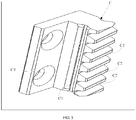
- each of the sub guide rails C includes: a guiding guide rail C1 and a drive rack C2.
- the guiding guide rail C1 is configured to guide the fiber patch cord apparatus
- the drive rack C2 is arranged in an array along the second direction, and are configured to engage with a drive gear of the fiber patch cord apparatus, so that the fiber patch cord apparatus moves along a guiding direction of the guiding guide rail C1.
- each of the sub guide rails C is provided with fastening holes C3, and can be fastened to the mold strip 4012 by means of the fastening holes C3 by using a screw.
- the sliding structure is in elastic contact with the guiding guide rail on the crawling guide rail formed by connecting the sub guide rails C, and the guiding direction of the guiding guide rail is parallel to the second direction.
- pressing force of two rows of the balls may be manually adjusted.
- the tuning screw 1044 is adjusted to a direction close to the balls A, compression thrust of the first elastic element 1043 can be increased, and then a distance between two opposite balls decreases as the compression thrust of the first elastic element 1043 increases, so that friction of the balls A on the guiding guide rail is increased.
- a ball slides, in a manner of being in elastic contact with the guiding guide rail, on the guiding guide rail, that is, the fiber patch cord apparatus slides, in a ball rolling manner, on the guiding guide rail; and the first elastic element 1043 can be adjusted to increase or decrease the compression thrust of the first elastic element 1043, that is, to increase or decrease the friction on the guiding guide rail of the ball, so as to adapt to a processing error and a splicing error of the guiding guide rail.
- the clamping unit 20 of the fiber patch cord apparatus 1 includes: a clamping element 201, a bolt 202, a clamping motor 203, and a clamping jaw 204.
- the clamping element 201 may be a U-shaped clamping element, and the U-shaped clamping element is provided with a screw hole 2011 and a first opening 2012 that has a chamfer. It is assumed that the clamping element 201 in this embodiment of the present invention is the U-shaped clamping element 201; and then, as shown in FIG. 6 , the bolt 202 may be connected to the U-shaped clamping element 201 by using the screw hole 2011, and the bolt 202 is connected to the clamping motor 203.
- a second elastic element 2041 is disposed on the clamping jaw 204, and the second elastic element 2041 provides an elastic force parallel to the first direction for the clamping jaw 204.
- the U-shaped clamping element 201 is sleeved on the clamping jaw 204 by means of the first opening 2012, and the second elastic element 2041 may be a compression spring.
- the clamping motor runs to drive the bolt to move along the second direction, and the bolt is connected to the U-shaped clamping element; in this case, the U-shaped clamping element is driven to also move along the second direction, and the U-shaped clamping element enables the clamping jaw to perform clamping or spread.
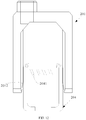
- the pulling and insertion unit 30 of the fiber patch cord apparatus 1 includes: a sliding element 301, a rotating shaft 302, a first bevel gear 303, a second bevel gear 304, and a pulling and insertion motor 305.
- the sliding element 301 is connected to the clamping jaw 204, the sliding element 301 is connected to the rotating shaft 302, the rotating shaft 302 is connected to the first bevel gear 303, the first bevel gear 303 is engaged with the second bevel gear 304, and the second bevel gear 304 is connected to the pulling and insertion motor 305.
- the pulling and insertion motor runs to drive the second bevel gear to rotate, and the second bevel gear is engaged with the first bevel gear; in this case, the first bevel gear is driven to drive the rotating shaft to rotate, so that the sliding element slides on the rotating shaft, thereby driving the clamping jaw connected to the sliding element to pull or insert, along a third direction, the fiber patch cord, where the third direction is a direction perpendicular to a plane constituted by the first direction and the second direction.
- FIG. 15 and FIG. 16 a process in which the pulling and insertion unit pulls and inserts a fiber patch cord.
- the pulling and insertion motor 305 of the pulling and insertion unit 30 runs to drive the second bevel gear 304 to rotate, and the second bevel gear 304 is engaged with the first bevel gear 303; in this case, the first bevel gear 303 is driven to drive the rotating shaft 302 to rotate, so that the sliding element 301 slides on the rotating shaft 302, thereby driving the clamping jaw 204 connected to the sliding element 301 to pull, along the third direction, the fiber patch cord 22 out of the source adapter port.
- FIG. 15 shows that after the U-shaped clamping element 201 drives the clamping jaw 204 to clamp the fiber patch cord 22
- the pulling and insertion motor 305 of the pulling and insertion unit 30 runs to drive the second bevel gear 304 to rotate, and the second bevel gear 304 is engaged with the first bevel gear 303; in this case, the first bevel gear 303 is driven to drive the rotating shaft 302 to rotate, so that the sliding element 301 slides on the rotating shaft 302, thereby driving the clamping jaw 204 connected to the sliding element
- the fiber patch cord apparatus moves to the target adapter port into which the fiber patch cord needs to be inserted, the pulling and insertion motor 305 of the pulling and insertion unit 30 runs to drive the second bevel gear 304 to rotate, and the second bevel gear 304 is engaged with the first bevel gear 303; in this case, the first bevel gear 303 is driven to drive the rotating shaft 302 to rotate, so that the sliding element 301 slides on the rotating shaft 302, thereby drive thing clamping jaw 204 connected to the sliding element 301 to insert, along the third direction, the fiber patch cord 22 into the target adapter port.
- an RFID (Radio Frequency Identification, radio frequency identification) read head is further disposed on the fiber patch cord apparatus, and is configured to read information about a radio frequency identification label on a fiber patch cord, so that the fiber patch cord apparatus identifies a fiber patch cord that needs to be pulled and inserted, so as to correctly perform the pulling and insertion and establish information about pairing between the fiber patch cord and an adapter port.
- information about a radio frequency identification label on a fiber patch cord inserted into the adapter port is stored in the RFID read head.
- the radio frequency identification is a wireless communications technology, and can identify a specific target by using a radio signal and read/write-related data, without a need of establishing mechanical or optical contact between an identification system and the specific target.
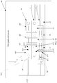
- an overall structure of the fiber patch cord apparatus 1 includes the crawling gear 101, the drive worm 102, the crawling motor 103, the sliding structure 104, the clamping element 201, the bolt 202, the clamping motor 203, the clamping jaw 204, the sliding element 301, the rotating shaft 302, the first bevel gear 303, the second bevel gear 304, the pulling and insertion motor 305, and the radio frequency identification read head 306, where the radio frequency identification read head 306 may be fastened to the sliding structure 104.
- the radio frequency identification read head 306 may be fastened to the sliding structure 104.
- An embodiment of the present invention provides a port panel 40, which, as shown in FIG. 2 , includes:
- At least two mold strip groups and at least two guide posts are disposed on a port panel, each of the guide posts is connected to the mold strip group, a sub guide rail is disposed on the mold strip group, and the mold strip group can move on the guide post, so as to drive a fiber patch cord apparatus on the sub guide rail of the mold strip group to move, which implements patching of a fiber patch cord, thereby simplifying a structure of a fiber patch cord system is simplified.
- a network port 4011 is disposed on each of the mold strip groups 401, and each of the mold strip groups 401 includes at least two mold strips 4012; the mold strips 4012 are arranged in an array along the second direction, and an adapter port B is disposed on each of the mold strips 4012, where the adapter port B may be an optical port that is configured to connect to an optical fiber, and is a passive connector; and a sub guide rail C is disposed at a first position of each of the mold strips 4012, where the first position may be a position parallel to the adapter port B along the first direction, and a guiding direction of the sub guide rail C is parallel to the second direction.
- the port panel further includes a special mold strip group, where the special mold strip group includes only a sub guide rail and a network port, does not include an adapter port, and is configured to form a crawling guide rail by being connected to a sub guide rail of a mold strip group adjacent to the sub guide rail of the special mold strip group, so as to pull a fiber patch cord out of an adapter port of the adjacent mold strip group or insert a fiber patch cord into an adapter port of the adjacent mold strip group.
- the special mold strip group includes only a sub guide rail and a network port, does not include an adapter port, and is configured to form a crawling guide rail by being connected to a sub guide rail of a mold strip group adjacent to the sub guide rail of the special mold strip group, so as to pull a fiber patch cord out of an adapter port of the adjacent mold strip group or insert a fiber patch cord into an adapter port of the adjacent mold strip group.
- a mold strip group 403 is adjacent to a mold strip group 401, and after the mold strip group 403 moves along the first direction, a sub guide rail of the special mold strip group 403 and a sub guide rail of the adjacent mold strip group 401 form a crawling guide rail, to pull a fiber patch cord out of an adapter port of the adjacent mold strip group 401 or insert a fiber patch cord into an adapter port of the adjacent mold strip group 401.
- each of the mold strip groups may be controlled by a controller to move along the first direction, and a distance by which each of the mold strip groups moves is less than a length of each of the mold strip groups that moves along the first direction.
- the distance by which each of the mold strip groups moves may be 3 centimeters, which is only exemplarily described and is not limited in this embodiment of the present invention. In this way, compared with the prior art, in this embodiment, because a distance by which a mold strip group moves is relatively short, space utilization of a fiber distribution terminal is effectively improved.
- each of the sub guide rails C includes: a guiding guide rail C1 and a drive rack C2.
- the guiding guide rail C1 is configured to guide the fiber patch cord apparatus, and the drive rack C2 is arranged in an array along the second direction, and are configured to engage with a drive gear of the fiber patch cord apparatus, so that the fiber patch cord apparatus moves along a guiding direction of the guiding guide rail C1.
- each of the sub guide rails C is provided with fastening holes C3, and can be fastened to the mold strip 4012 by means of the fastening holes C3 by using a screw.
- the crawling guide rail is formed by connecting the sub guide rail on the first mold strip to the sub guide rail on the at least one mold strip adjacent to the first mold strip in the second direction, so that the fiber patch cord apparatus can move along the crawling guide rail, where the first mold strip is any mold strip in the at least two mold strip groups.
- FIG. 20 and FIG. 21 a process in which a mold strip group on a port panel moves.
- a port panel 50 includes a first mold strip group 501, a second mold strip group 502, a third mold strip group 503, and guide posts 504, where the first mold strip group 501 includes a mold strip 5011, a mold strip 5012, and a mold strip 5013, the second mold strip group 502 includes a mold strip 5021, a mold strip 5022, and a mold strip 5023, and the third mold strip group 503 includes a mold strip 5031, a mold strip 5032, and a mold strip 5033.
- the second mold strip group 502 moves on the guide post 504 along the first direction; in this case, a sub guide rail of the mold strip 5022 of the second mold strip group 502 is aligned with a sub guide rail of the mold strip 5013 of the first mold strip group 501 and a sub guide rail of the mold strip 5033 of the third mold strip group 503, to form a crawling guide rail.
- An embodiment of the present invention provides a fiber patch cord system 60, which, as shown in FIG. 22 , includes: a fiber patch cord apparatus 601, a port panel 602, a controller 603, and a fiber distribution terminal (which is not drawn in FIG. 22 ).
- the fiber patch cord apparatus 601 is configured to: move to a corresponding position of a source adapter port along a crawling guide rail provided by the port panel 602, clamp a fiber patch cord on the source adapter port, and pull the fiber patch cord out of the source adapter port, or insert the fiber patch cord into the target adapter port, where the fiber patch cord apparatus is located on the port panel 602.
- the port panel 602 is configured to provide the crawling guide rail for the fiber patch cord apparatus 601.
- the controller 603 is configured to control the fiber patch cord apparatus 601 to move on the crawling guide rail.
- the controller 603 is further configured to control a mold strip group 6021 of the port panel 602 to move.
- the fiber distribution terminal is configured to protect the fiber patch cord apparatus 601, the port panel 602, and the controller 603, and the fiber patch cord apparatus 601, the port panel 602, and the controller 603 are located inside the fiber distribution terminal.
- the controller may be connected to a crawling motor of the fiber patch cord apparatus 601 by using a wire, so that the fiber patch cord apparatus 601 moves on the crawling guide rail according to crawling path information sent by the controller 603.
- the controller 603 sends control information to each of the mold strip groups according to an address of a network port of each of the mold strip groups by using a network cable and the network port of each of the mold strip groups, so that each of the mold strip groups moves on a guide post according to the control information.
- each of the mold strip groups 6021 in the port panel 602 may be connected to the controller 603 by using a network cable b, and the fiber patch cord apparatus 601 may be connected to the controller 603 by using a wire a.
- the mold strip groups 6021 in the fiber patch cord system 60 include a first mold strip group m, a second mold strip group n, and a third mold strip group d.
- the first mold strip group m includes a mold strip m1, a mold strip m2, and a mold strip m3, where the mold strip m1 includes a sub guide rail m11 and an adapter port m12, the mold strip m2 includes a sub guide rail m21 and an adapter port m22, and the mold strip m3 includes a sub guide rail m31 and an adapter port m32;
- the second mold strip group n includes a mold strip n1, a mold strip n2, and a mold strip n3, where the mold strip n1 includes a sub guide rail n11 and an adapter port n12, the mold strip n2 includes a sub guide rail n21 and an adapter port n22, and the mold strip n3 includes a sub guide rail n31 and an
- the sub guide rail m11, the sub guide rail n11, and the sub guide rail d11 form a crawling guide rail; and similarly, the sub guide rail m21, the sub guide rail n21, and the sub guide rail d21 form a crawling guide rail, and the sub guide rail m31, the sub guide rail n31, and the sub guide rail d31 form a crawling guide rail.
- the source adapter port is the adapter port n12 of the mold strip n1 of the second mold strip group n
- the target adapter port is the adapter port d12 of the mold strip d1 of the third mold strip group d3
- the fiber patch cord apparatus 601 is currently located on the sub guide rail m11 of the mold strip m1 of the first mold strip group m.
- the second mold strip group n can move on the guide post 6022 along the first direction, so that the adapter port n12 of the mold strip n1 of the second mold strip group n is aligned with the sub guide rail m11 of the mold strip m1 of the first mold strip group m, and then the fiber patch cord apparatus 601 pulls, along a third direction, the fiber patch cord out of the source adapter port.
- the second mold strip group n may move again on the guide post 6022 along the first direction according to the control information, so that the sub guide rail n11 of the mold strip n1 of the second mold strip group n is aligned with the sub guide rail m11 of the mold strip m1 of the first mold strip group m, to form a crawling guide rail; in addition, after the third mold strip group d receives, by using the network port M, the control information sent by the controller 603, the third mold strip group d may move on the guide post 6022 along the first direction, so that the adapter port d12 of the mold strip d1 of the third mold strip group d is aligned with the sub guide rail n11 of the mold strip n1 of the second mold strip group n.
- the fiber patch cord apparatus 601 may move to the sub guide rail n11 of the mold strip n1 of the second mold strip group n along the second direction, and then the fiber patch cord apparatus 601 inserts, along the third direction, the fiber patch cord into the target adapter port.
- the second direction is perpendicular to the first direction
- the first direction is a row direction or a column direction
- the row direction is a direction parallel to a placement surface when the fiber distribution terminal is normally placed
- the column direction is a direction perpendicular to the placement surface when the fiber distribution terminal is normally placed
- the third direction is a direction perpendicular to a plane constituted by the first direction and the second direction.
- the fiber patch cord process of the fiber patch cord system provided in this embodiment of the present invention is only exemplarily described, and is not limited.
- a specific fiber patch cord process based on a patching path algorithm is the same as that in the prior art, and details are not provided herein again.
- a fiber patch cord apparatus includes a crawling unit, configured to move to a corresponding position of a source adapter port along a crawling guide rail provided by a port panel; a clamping unit, configured to clamp a fiber patch cord on the source adapter port; and a pulling and insertion unit, configured to pull the fiber patch cord out of the source adapter port, or insert the fiber patch cord into a target adapter port.
- the port panel includes at least two mold strip groups and at least two guide posts, where each of the guide posts is connected to the mold strip group, so that the mold strip group can be controlled by a controller to move on the guide post connected to the mold strip group; in this way, the fiber patch cord apparatus and the port panel coordinate with each other, so that a structure of a fiber patch cord system by which a fiber patch cord is automatically pulled out of or inserted into an adapter port disposed on the port panel is simplified.
Landscapes
- Physics & Mathematics (AREA)
- General Physics & Mathematics (AREA)
- Optics & Photonics (AREA)
- Moulding By Coating Moulds (AREA)
- Light Guides In General And Applications Therefor (AREA)
- Optical Fibers, Optical Fiber Cores, And Optical Fiber Bundles (AREA)
Description
- The present invention relates to the field of communications, and in particular, to a fiber patch cord apparatus, a port panel, and a fiber patch cord system.
- FTTX (Fiber-To-The-x) refers to connecting an optical fiber to an actual scenario, where x may be H, that is, FTTH (Fiber-To-The-Home), or x may be P, that is, FTTP (Fiber-To-The-Premises), or x may be O, that is, FTTO (Fiber-To-The-Office), or another scenario. Before a large quantity of FTTX networks are built or after a large quantity of FTTX networks are built, massive optical fibers on an FTTX network need to be maintained and managed, for example, in procedures of initial building of an FTTX network, provisioning of a newly-added user service, and an optical fiber troubleshooting service, operations such as diagnosis, locating, patching, detection, recording, and refreshing need to be performed on a network port connected to an optical fiber, and the operations are very frequent. However, after an optical fiber maintenance command is received, patching cannot be accurately performed on an optical fiber in time during a manual patching operation; and there are defects in aspects of accuracy, timeliness, and simplicity of optical fiber maintenance.
- In the prior art, a fiber patch cord system includes a fiber distribution terminal, a port panel, a robotic arm, where the port panel and the robotic arm are located inside the fiber distribution terminal, and the port panel may be a two-dimensional port panel. Several adapter ports are disposed along a row direction and a column direction according to a space size of the fiber distribution terminal, where the row direction is a direction parallel to a placement surface when the fiber distribution terminal is normally placed, and the column direction is a direction perpendicular to the placement surface when the fiber distribution terminal is normally placed; and then the robotic arm may be used to move through the two-dimensional port panel, and the robotic arm may be moved to a specified adapter port to perform pulling, insertion, and patching of an optical fiber. However, when a column needs to be changed, a group of single-shaft column change and movement modules is further needed to drive the entire robotic arm to complete a column change action, and the robotic arm is relatively long and is not telescopic, which increases a volume of the fiber distribution terminal. The port panel may also be changed to be of a space matrix structure. In a row direction of a matrix, one robot is disposed to control and complete pulling, insertion, and patching of an optical fiber in the row direction; and in a column direction of the matrix, one robot further needs to be disposed to control and complete pulling, insertion, and patching of an optical fiber in the column direction. In this way, not only movement control is complex, but also the robots occupy relatively large space of the fiber distribution terminal, leading to a decrease in adapter ports disposed on the port panel of the fiber distribution terminal. Therefore, the fiber patch cord system has a complex structure.
-
US5386485A discloses an optical fiber switching device having a coupling board comprising a plurality of first optical fibers connected to one surface of the coupling board in the arrangement to one surface of the coupling board, a plurality of second optical fibers connected to the another surface of the coupling board, an optical fiber length adjusting unit for handling surplus portions of the second optical fibers and switching unit for pulling out any one of the second optical fibers selected from the plural second optical fibers from the another surface of the connecting board and for connecting the any one optical fiber to different switching position of the another surface of the connecting board to coupling the any one optical fiber with any one of the first optical fibers. - Embodiments of the present invention provide a fiber patch cord apparatus, a port panel, and a fiber patch cord system, which can simplify a structure of the fiber patch cord system.
- To achieve the foregoing objective, the following technical solutions are used in the embodiments of the present invention:
- According to a first aspect, a fiber patch cord apparatus is provided, including:
- a crawling unit, configured to move to a corresponding position of a source adapter port on a crawling guide rail provided by a port panel;
- a clamping unit, configured to clamp a fiber patch cord on the source adapter port; and
- a pulling and insertion unit, configured to pull the fiber patch cord out of the source adapter port, where
- the crawling unit is further configured to move to a corresponding position of a target adapter port on the crawling guide rail provided by the port panel;
- the pulling and insertion unit is further configured to insert the fiber patch cord into the target adapter port; and
- the fiber patch cord apparatus is adapted to be located on the port panel, the crawling guide rail is formed by connecting a sub guide rail on a first mold strip to a sub guide rail on at least one mold strip adjacent to the first mold strip in a second direction, the first mold strip is any mold strip in at least two mold strip groups arranged in an array on the port panel along a second direction, each of the mold strip groups can move along the first direction, each of the mold strip groups includes at least two mold strips arranged in an array along the first direction, an adapter port is disposed on each of the mold strips, and the second direction is perpendicular to the first direction.
- With reference to the first aspect, in a first implementable manner, the crawling unit includes:
- a crawling gear, where the crawling gear can be engaged with a drive rack arranged in an array on the crawling guide rail along the second direction;
- a sliding structure, where the sliding structure is connected to the crawling gear, the sliding structure is in contact with a guiding guide rail on the crawling guide rail, and a guiding direction of the guiding guide rail is parallel to the second direction;
- a drive worm; and
- a crawling motor, where the crawling motor is connected to the crawling gear by using the drive worm and is configured to: drive the crawling gear to be engaged with the drive rack, and drive the sliding structure to move along the guiding direction of the guiding guide rail.
- With reference to the first implementable manner, in a second implementable manner, the sliding structure includes:
- at least two ball groups, where balls in each of the ball groups are arranged in a linear array along the second direction; and
- a first elastic element connected to the ball is disposed corresponding to any ball in a first ball group, so that the ball is in elastic contact with the guiding guide rail, where the first ball group is at least one ball group in the two ball groups.
- With reference to the first aspect, in a third implementable manner, the clamping unit includes:
- a clamping element, where the clamping element is provided with a screw hole and a first opening that has a chamfer;
- a bolt, where the bolt is connected to the clamping element by using the screw hole;
- a clamping motor, where the clamping motor drives, by using the bolt, the clamping element to move along a direction parallel to the second direction; and
- a clamping jaw, where a second elastic element is disposed on the clamping jaw, the second elastic element provides an elastic force parallel to the first direction for the clamping jaw, and the clamping element is sleeved on the clamping jaw by means of the first opening, where
- when the clamping element moves along the direction parallel to the second direction to make a contact area between the first opening and the clamping jaw gradually increase, the clamping jaw is driven by an elastic force of the first opening to perform clamping; or
- when the clamping element moves along the direction parallel to the second direction to make a contact area between the first opening and the clamping jaw gradually decrease, the clamping jaw is driven by an elastic force of the first opening to spread.
- With reference to the third implementable manner, in a fourth implementable manner, the pulling and insertion unit includes:
- a sliding element, where the sliding element is connected to the clamping jaw;
- a rotating shaft, where the rotating shaft is connected to the sliding element;
- a first bevel gear, where the first bevel gear is connected to the rotating shaft;
- a second bevel gear, where the second bevel gear is engaged with the first bevel gear; and
- a pulling and insertion motor, where the pulling and insertion motor is connected to the first bevel gear by using the second bevel gear, and is configured to: drive the second bevel gear to be engaged with the first bevel gear, and drive the rotating shaft to rotate, so as to enable the sliding element to slide on the rotating shaft, thereby driving the clamping jaw connected to the sliding element to pull or insert, along a third direction, the fiber patch cord, where the third direction is a direction perpendicular to a plane constituted by the first direction and the second direction.
- With reference to the first aspect, in a fifth implementable manner, the fiber patch cord apparatus includes:
- a radio frequency identification read head, configured to read information about a radio frequency identification label on a fiber patch cord of an adapter port on the mold strip group. With reference to the first implementable manner, in a sixth implementable manner, crawling motor is connected to the controller, and is configured to: receive crawling path information sent by the controller and control, according to the crawling path information, the fiber patch cord apparatus to move on the crawling guide rail.
- According to a second aspect, a port panel is provided, including:
- at least two mold strip groups arranged in an array along a second direction; and
- at least two guide posts, where each of the guide posts is connected to the mold strip group, to enable the mold strip group to move along the first direction by using the guide post, where
- each of the mold strip groups includes at least two mold strips arranged in an array along a first direction, where the second direction is perpendicular to the first direction; and
- an adapter port is disposed on each of the mold strips, a sub guide rail is disposed at a first position of each of the mold strips, and a guiding direction of the sub guide rail is parallel to the second direction, where
- a crawling guide rail is formed by connecting a sub guide rail on a first mold strip to a sub guide rail on at least one mold strip adjacent to the first mold strip in the second direction, so that a fiber patch cord apparatus can move along the crawling guide rail, and the first mold strip is any mold strip in the at least two mold strip groups.
- With reference to the second aspect, in a first implementable manner, of the sub guide rails includes:
- a guiding guide rail, configured to guide the fiber patch cord apparatus, where a guiding direction of the guiding guide rail is parallel to the second direction; and
- a drive rack, arranged in an array along the second direction, and configured to engage with a drive gear of the fiber patch cord apparatus, to enable the fiber patch cord apparatus to move along the guiding direction of the guiding guide rail.
- With reference to the first implementable manner, in a second implementable manner, a network port is disposed on each of the mold strip groups, and the mold strip group is connected to a controller by using the network port, and moves along the first direction according to control information of the controller.
- With reference to the second implementable manner, in a third implementable manner, distance by which each of the mold strip groups moves is less than a length of each of the mold strip groups that moves along the first direction.
- According to a third aspect, a fiber patch cord system is provided, including:
- any fiber patch cord apparatus described above;
- any port panel described above;
- a controller, configured to control the fiber patch cord apparatus to move on a crawling guide rail, where
- the controller is further configured to control a mold strip group on the port panel to move; and
- a fiber distribution terminal, configured to protect the fiber patch cord apparatus, the port panel, and the controller.
- The embodiments of the present invention provide a fiber patch cord apparatus, a port panel, and a fiber patch cord system. The fiber patch cord apparatus includes: a crawling unit, configured to move to a corresponding position of a source adapter port along a crawling guide rail provided by a port panel; a clamping unit, configured to clamp a fiber patch cord on the source adapter port; and a pulling and insertion unit, configured to pull the fiber patch cord out of the source adapter port, where the pulling and insertion unit is further configured to insert the fiber patch cord into the target adapter port. The port panel includes a fiber patch cord apparatus, a port panel, and a controller that is configured to control the fiber patch cord apparatus to move on a crawling guide rail, where the controller is further configured to control a mold strip group on the port panel to move. In this way, the fiber patch cord apparatus and the port panel coordinate with each other, so that a structure of the fiber patch cord system by which a fiber patch cord is automatically pulled out of and inserted into an adapter port disposed on the port panel is simplified.
- To describe the technical solutions in the embodiments of the present invention or in the prior art more clearly, the following briefly introduces the accompanying drawings required for describing the embodiments or the prior art. Apparently, the accompanying drawings in the following description show merely some embodiments of the present invention, and a person of ordinary skill in the art may still derive other drawings from these accompanying drawings without creative efforts.
-
FIG. 1 is a schematic structural diagram of a fiber patch cord apparatus according to an embodiment of the present invention; -
FIG. 2 is a schematic structural diagram of a port panel according to an embodiment of the present invention; -
FIG. 3 is a schematic structural diagram of another fiber patch cord apparatus according to an embodiment of the present invention; -
FIG. 4 is a schematic structural diagram of still another fiber patch cord apparatus according to an embodiment of the present invention; -
FIG. 5 is a schematic structural diagram of another port panel according to an embodiment of the present invention; -
FIG. 6 is a schematic structural diagram of yet another fiber patch cord apparatus according to an embodiment of the present invention; -
FIG. 7 is a schematic structural diagram of still yet another fiber patch cord apparatus according to an embodiment of the present invention; -
FIG. 8 is a schematic structural diagram of a further fiber patch cord apparatus according to an embodiment of the present invention; -
FIG. 9 is schematic diagram 1 of a process in which a U-shaped clamping element clamps a clamping jaw according to an embodiment of the present invention; -
FIG. 10 is schematic diagram 2 of a process in which a U-shaped clamping element clamps a clamping jaw according to an embodiment of the present invention; -
FIG. 11 is schematic diagram 3 of a process in which a U-shaped clamping element clamps a clamping jaw according to an embodiment of the present invention; -
FIG. 12 is schematic diagram 1 of a process in which a U-shaped clamping element spreads a clamping jaw according to an embodiment of the present invention; -
FIG. 13 is schematic diagram 2 of a process in which a U-shaped clamping element spreads a clamping jaw according to an embodiment of the present invention; -
FIG. 14 is a schematic structural diagram of a still further fiber patch cord apparatus according to an embodiment of the present invention; -
FIG. 15 is schematic diagram 1 of a process in which a pulling and insertion unit pulls and inserts a fiber patch cord according to an embodiment of the present invention; -
FIG. 16 is schematic diagram 2 of a process in which a pulling and insertion unit pulls and inserts a fiber patch cord according to an embodiment of the present invention; -
FIG. 17 is a schematic structural diagram of a yet further fiber patch cord apparatus according to an embodiment of the present invention; -
FIG. 18 is a schematic structural diagram of still another port panel according to an embodiment of the present invention; -
FIG. 19 is a schematic structural diagram of yet another port panel according to an embodiment of the present invention; -
FIG. 20 is schematic diagram 1 of a process in which a mold strip group on a port panel moves according to an embodiment of the present invention; -
FIG. 21 is schematic diagram 2 of a process in which a mold strip group on a port panel moves according to an embodiment of the present invention; -
FIG. 22 is a schematic diagram of a fiber patch cord system according to an embodiment of the present invention; -
FIG. 23 is schematic diagram 1 of a fiber patch cord process of a fiber patch cord system according to an embodiment of the present invention; -
FIG. 24 is schematic diagram 2 of a fiber patch cord process of a fiber patch cord system according to an embodiment of the present invention; -
FIG. 25 is schematic diagram 3 of a fiber patch cord process of a fiber patch cord system according to an embodiment of the present invention; and -
FIG. 26 is schematic diagram 4 of a fiber patch cord process of a fiber patch cord system according to an embodiment of the present invention. - The following clearly and completely describes the technical solutions in the embodiments of the present invention with reference to the accompanying drawings in the embodiments of the present invention. Apparently, the described embodiments are merely some but not all of the embodiments of the present invention. All other embodiments obtained by a person of ordinary skill in the art based on the embodiments of the present invention without creative efforts shall fall within the protection scope of the present invention.
- Embodiments of the present invention provide a fiber patch cord system, including: a fiber distribution terminal, a fiber patch cord apparatus, a port panel, and a controller. The fiber patch cord apparatus, the port panel, and the controller are located inside the fiber distribution terminal, the fiber patch cord apparatus is located on the port panel, and the fiber patch cord apparatus is configured to move to a corresponding position of a source adapter port along a crawling guide rail provided by the port panel, clamp a fiber patch cord on the source adapter port, and pull the fiber patch cord out of the source adapter port, or insert the fiber patch cord into the target adapter port, where the source adapter port is an adapter port on which the fiber patch cord that needs to be pulled out is located, and the target adapter port is an adapter port into which the fiber patch cord needs to be inserted. The port panel is configured to provide the crawling guide rail for the fiber patch cord apparatus. The controller is configured to control the fiber patch cord apparatus to move on the crawling guide rail, the controller is connected to the fiber patch cord apparatus and the port panel, and the controller is configured to control the fiber patch cord apparatus to move on the crawling guide rail; and the controller is further configured to control a mold strip group on the port panel to move.
- Specifically, an embodiment of the present invention provides a fiber
patch cord apparatus 1, which, as shown inFIG. 1 , includes: - a
crawling unit 10, configured to move to a corresponding position of a source adapter port along a crawling guide rail provided by a port panel; - a
clamping unit 20, configured to clamp a fiber patch cord on the source adapter port; and - a pulling and
insertion unit 30, configured to pull the fiber patch cord out of the source adapter port, where - the crawling
unit 10 is further configured to move to a corresponding position of a target adapter port along the crawling guide rail provided by the port panel; - the pulling and
insertion unit 30 is further configured to insert the fiber patch cord into the target adapter port; and - the fiber patch cord apparatus is located on the port panel, the crawling guide rail is formed by connecting a sub guide rail on a first mold strip to a sub guide rail on at least one mold strip adjacent to the first mold strip in a second direction, the first mold strip is any mold strip in at least two mold strip groups arranged in an array on the port panel along a first direction, each of the mold strip groups can move along the first direction, each of the mold strip groups includes at least two mold strips arranged in an array along the second direction, an adapter port is disposed on each of the mold strips, the second direction is perpendicular to the first direction, and the first direction is a row direction or a column direction, where the row direction is a direction parallel to a placement surface when the fiber distribution terminal is normally placed, and the column direction is a direction perpendicular to the placement surface when the fiber distribution terminal is normally placed.
- In this way, the fiber patch cord apparatus moves to the corresponding position of the source adapter port on the crawling guide rail provided by the port panel, then, pulls the fiber patch cord out of the source adapter port after clamping the fiber patch cord on the source adapter port, and then, moves to the corresponding position of the target adapter port on the crawling guide rail provided by the port panel, and inserts the fiber patch cord into the target adapter port, so as to perform patching on the fiber patch cord on the adapter port of the port panel, which simplifies a structure of the fiber patch cord system.
- It should be noted that, as shown in
FIG. 2 , theport panel 40 includes at least twomold strip groups 401 arranged in an array along the first direction, and at least two guide posts 402. Each of the guide posts 402 is connected to themold strip group 401, and each of themold strip groups 401 includes anetwork port 4011 and at least twomold strips 4012 arranged in an array along the second direction. A sub guide rail C is disposed on each of the mold strips 4012, and a guiding direction of the sub guide rail C is parallel to the second direction. The crawling guide rail is formed by connecting the sub guide rail on the first mold strip to the sub guide rail on the at least one mold strip adjacent to the first mold strip in the second direction. The first mold strip is any mold strip in the at least two mold strip groups. The second direction is perpendicular to the first direction. Therefore, the fiber patch cord apparatus can move along the crawling guide rail. The second direction is perpendicular to the first direction; in this case, assuming that the first direction is an X direction inFIG. 2 , the second direction is a Y direction inFIG. 2 . - Specifically, as shown in
FIG. 3 , the crawlingunit 10 of the fiberpatch cord apparatus 1 includes: acrawling gear 101, adrive worm 102, a crawlingmotor 103, and a housing (which is not drawn inFIG. 2 ). The housing is configured to protect and fasten an internal unit of the fiberpatch cord apparatus 1. Thecrawling gear 101 and thedrive worm 102 are enveloped by the housing, and thecrawling gear 101 is fastened to the housing at agear center 1011 of the crawling gear, is engaged with adrive rack 11 arranged in an array on the crawling guide rail along the second direction, and is further engaged with thedrive worm 102. The crawlingmotor 103 is connected to thedrive worm 102. - When the crawling
motor 103 runs to drive thedrive worm 102 to rotate spirally, thecrawling gear 101 of the crawlingunit 10 of the fiberpatch cord apparatus 1 is engaged with thedrive worm 102, to drive thecrawling gear 101 to rotate; at the same time, thecrawling gear 101 is engaged with the drive rack on the crawling guide rail disposed on the port panel, to drive thecrawling gear 101 to move on the crawling guide rail along the second direction, so that the fiber patch cord apparatus moves, on the crawling guide rail disposed on the port panel, along the second direction. - Further, the crawling
unit 10 further includes a slidingstructure 104. Specifically, as shown inFIG. 4 , the slidingstructure 104 is fastened to the housing (which is not shown inFIG. 4 ) that envelopes thecrawling gear 101 and thedrive worm 102, and the slidingstructure 104 includes at least twoball groups 1041, where balls A in each of theball groups 1041 are arranged in a linear array along the second direction, and the balls A may be steel balls. A firstelastic element 1043 connected to the ball is disposed corresponding to any ball in a first ball group, where the first ball group is at least one ball group in the two ball groups. As shown inFIG. 4 , each of the balls A is fastened to aholder 1042, theholder 1042 is connected to the firstelastic element 1043, and the firstelastic element 1043 is connected to atuning screw 1044, where the firstelastic element 1043 may be a compression spring, and thetuning screw 1044 may be a fastening screw. - It should be noted that, the ball is in elastic contact with a guiding guide rail of the sub guide rail disposed on the port panel. Specifically, as shown in
FIG. 5 , each of the sub guide rails C includes: a guiding guide rail C1 and a drive rack C2. The guiding guide rail C1 is configured to guide the fiber patch cord apparatus, and the drive rack C2 is arranged in an array along the second direction, and are configured to engage with a drive gear of the fiber patch cord apparatus, so that the fiber patch cord apparatus moves along a guiding direction of the guiding guide rail C1. Particularly, each of the sub guide rails C is provided with fastening holes C3, and can be fastened to themold strip 4012 by means of the fastening holes C3 by using a screw. That is, the sliding structure is in elastic contact with the guiding guide rail on the crawling guide rail formed by connecting the sub guide rails C, and the guiding direction of the guiding guide rail is parallel to the second direction. Particularly, pressing force of two rows of the balls may be manually adjusted. For example, when thetuning screw 1044 is adjusted to a direction close to the balls A, compression thrust of the firstelastic element 1043 can be increased, and then a distance between two opposite balls decreases as the compression thrust of the firstelastic element 1043 increases, so that friction of the balls A on the guiding guide rail is increased. When thetuning screw 1044 is adjusted to a direction away from the balls A, compression thrust of the firstelastic element 1043 can be decreased, and then a distance between two opposite balls increases as the compression thrust of the firstelastic element 1043 decreases, so that friction of the balls A on the guiding guide rail is decreased. In this way, a ball slides, in a manner of being in elastic contact with the guiding guide rail, on the guiding guide rail, that is, the fiber patch cord apparatus slides, in a ball rolling manner, on the guiding guide rail; and the firstelastic element 1043 can be adjusted to increase or decrease the compression thrust of the firstelastic element 1043, that is, to increase or decrease the friction on the guiding guide rail of the ball, so as to adapt to a processing error and a splicing error of the guiding guide rail. - In addition, as shown in
FIG. 6 , the clampingunit 20 of the fiberpatch cord apparatus 1 includes: a clampingelement 201, abolt 202, a clampingmotor 203, and a clampingjaw 204. Exemplarily, as shown inFIG. 7 , the clampingelement 201 may be a U-shaped clamping element, and the U-shaped clamping element is provided with ascrew hole 2011 and afirst opening 2012 that has a chamfer. It is assumed that the clampingelement 201 in this embodiment of the present invention is theU-shaped clamping element 201; and then, as shown inFIG. 6 , thebolt 202 may be connected to theU-shaped clamping element 201 by using thescrew hole 2011, and thebolt 202 is connected to the clampingmotor 203. Exemplarily, as shown inFIG. 8 , a secondelastic element 2041 is disposed on the clampingjaw 204, and the secondelastic element 2041 provides an elastic force parallel to the first direction for the clampingjaw 204. TheU-shaped clamping element 201 is sleeved on the clampingjaw 204 by means of thefirst opening 2012, and the secondelastic element 2041 may be a compression spring.It should be noted that, the clamping motor runs to drive the bolt to move along the second direction, and the bolt is connected to the U-shaped clamping element; in this case, the U-shaped clamping element is driven to also move along the second direction, and the U-shaped clamping element enables the clamping jaw to perform clamping or spread. - Exemplarily, the following describes, by using
FIG. 9 to FIG. 13 , processes in which the U-shaped clamping element clamps the clamping jaw and spreads the clamping jaw. - As shown in
FIG. 9 to FIG. 11 , when a contact area between thefirst opening 2012 of theU-shaped clamping element 201 and the clampingjaw 204 gradually increases, thefirst opening 2012 contracts under the effect of the secondelastic element 2041 and the clampingjaw 204 performs clamping; and then when the clampingmotor 203 runs to drive thebolt 202 to drive theU-shaped clamping element 201 to also move along the second direction, the contact area between thefirst opening 2012 and the clampingjaw 204 gradually decreases. - As shown in
FIG. 12 andFIG. 13 , when theU-shaped clamping element 201 moves again along a direction parallel to the second direction, the contact area between thefirst opening 2012 and the clampingjaw 204 gradually increases again; and then when the clampingmotor 203 runs to drive thebolt 202 to drive theU-shaped clamping element 201 to also move along the second direction, the contact area between thefirst opening 2012 and the clampingjaw 204 gradually decreases, and in this case, thefirst opening 2012 stretches under the effect of the second elastic element, and the clampingjaw 204 spreads. - Specifically, as shown in
FIG. 14 , the pulling andinsertion unit 30 of the fiberpatch cord apparatus 1 includes: a slidingelement 301, arotating shaft 302, afirst bevel gear 303, asecond bevel gear 304, and a pulling andinsertion motor 305. The slidingelement 301 is connected to the clampingjaw 204, the slidingelement 301 is connected to therotating shaft 302, therotating shaft 302 is connected to thefirst bevel gear 303, thefirst bevel gear 303 is engaged with thesecond bevel gear 304, and thesecond bevel gear 304 is connected to the pulling andinsertion motor 305. - It should be noted that, when the pulling and insertion motor runs to drive the second bevel gear to rotate, and the second bevel gear is engaged with the first bevel gear; in this case, the first bevel gear is driven to drive the rotating shaft to rotate, so that the sliding element slides on the rotating shaft, thereby driving the clamping jaw connected to the sliding element to pull or insert, along a third direction, the fiber patch cord, where the third direction is a direction perpendicular to a plane constituted by the first direction and the second direction.
- Exemplarily, the following describes, by using
FIG. 15 andFIG. 16 , a process in which the pulling and insertion unit pulls and inserts a fiber patch cord. - As shown in
FIG. 15 , after theU-shaped clamping element 201 drives the clampingjaw 204 to clamp thefiber patch cord 22, the pulling andinsertion motor 305 of the pulling andinsertion unit 30 runs to drive thesecond bevel gear 304 to rotate, and thesecond bevel gear 304 is engaged with thefirst bevel gear 303; in this case, thefirst bevel gear 303 is driven to drive therotating shaft 302 to rotate, so that the slidingelement 301 slides on therotating shaft 302, thereby driving theclamping jaw 204 connected to the slidingelement 301 to pull, along the third direction, thefiber patch cord 22 out of the source adapter port. Then, as shown inFIG. 16 , the fiber patch cord apparatus moves to the target adapter port into which the fiber patch cord needs to be inserted, the pulling andinsertion motor 305 of the pulling andinsertion unit 30 runs to drive thesecond bevel gear 304 to rotate, and thesecond bevel gear 304 is engaged with thefirst bevel gear 303; in this case, thefirst bevel gear 303 is driven to drive therotating shaft 302 to rotate, so that the slidingelement 301 slides on therotating shaft 302, thereby drivething clamping jaw 204 connected to the slidingelement 301 to insert, along the third direction, thefiber patch cord 22 into the target adapter port. - It should be noted that, an RFID (Radio Frequency Identification, radio frequency identification) read head is further disposed on the fiber patch cord apparatus, and is configured to read information about a radio frequency identification label on a fiber patch cord, so that the fiber patch cord apparatus identifies a fiber patch cord that needs to be pulled and inserted, so as to correctly perform the pulling and insertion and establish information about pairing between the fiber patch cord and an adapter port. Particularly, information about a radio frequency identification label on a fiber patch cord inserted into the adapter port is stored in the RFID read head. The radio frequency identification is a wireless communications technology, and can identify a specific target by using a radio signal and read/write-related data, without a need of establishing mechanical or optical contact between an identification system and the specific target.
- Exemplarily, as shown in
FIG. 17 , an overall structure of the fiberpatch cord apparatus 1 includes thecrawling gear 101, thedrive worm 102, the crawlingmotor 103, the slidingstructure 104, the clampingelement 201, thebolt 202, the clampingmotor 203, the clampingjaw 204, the slidingelement 301, therotating shaft 302, thefirst bevel gear 303, thesecond bevel gear 304, the pulling andinsertion motor 305, and the radio frequency identification readhead 306, where the radio frequency identification readhead 306 may be fastened to the slidingstructure 104. For a specific connection relationship between units of the fiberpatch cord apparatus 1, reference may be made to the descriptions aboutFIG. 3 ,FIG. 4 ,FIG. 6 , andFIG. 14 . - An embodiment of the present invention provides a
port panel 40, which, as shown inFIG. 2 , includes: - at least two
mold strip groups 401 arranged in an array along a first direction; and - at least two
guide posts 402, where each of the guide posts 402 is connected to themold strip group 401, to enable themold strip group 401 to move along the first direction by using theguide post 402, where - each of the
mold strip groups 401 includes at least two mold strips arranged in an array along a second direction, where the second direction is perpendicular to the first direction; and - an adapter port is disposed on each of the mold strips, a sub guide rail is disposed at a first position of each of the mold strips, and a guiding direction of the sub guide rail is parallel to the second direction, where
- a crawling guide rail is formed by connecting a sub guide rail on a first mold strip to a sub guide rail on at least one mold strip adjacent to the first mold strip in the second direction, so that a fiber patch cord apparatus can move along the crawling guide rail, and the first mold strip is any mold strip in the at least two mold strip groups, the second direction is perpendicular to the first direction, and the first direction is a row direction or a column direction, where the row direction is a direction parallel to a placement surface when the fiber distribution terminal is normally placed, and the column direction is a direction perpendicular to the placement surface when the fiber distribution terminal is normally placed.
- In this way, at least two mold strip groups and at least two guide posts are disposed on a port panel, each of the guide posts is connected to the mold strip group, a sub guide rail is disposed on the mold strip group, and the mold strip group can move on the guide post, so as to drive a fiber patch cord apparatus on the sub guide rail of the mold strip group to move, which implements patching of a fiber patch cord, thereby simplifying a structure of a fiber patch cord system is simplified. Specifically, as shown in
FIG. 18 , anetwork port 4011 is disposed on each of themold strip groups 401, and each of themold strip groups 401 includes at least twomold strips 4012; the mold strips 4012 are arranged in an array along the second direction, and an adapter port B is disposed on each of the mold strips 4012, where the adapter port B may be an optical port that is configured to connect to an optical fiber, and is a passive connector; and a sub guide rail C is disposed at a first position of each of the mold strips 4012, where the first position may be a position parallel to the adapter port B along the first direction, and a guiding direction of the sub guide rail C is parallel to the second direction. - Particularly, the port panel further includes a special mold strip group, where the special mold strip group includes only a sub guide rail and a network port, does not include an adapter port, and is configured to form a crawling guide rail by being connected to a sub guide rail of a mold strip group adjacent to the sub guide rail of the special mold strip group, so as to pull a fiber patch cord out of an adapter port of the adjacent mold strip group or insert a fiber patch cord into an adapter port of the adjacent mold strip group. Exemplarily, as shown in
FIG. 19 , amold strip group 403 is adjacent to amold strip group 401, and after themold strip group 403 moves along the first direction, a sub guide rail of the specialmold strip group 403 and a sub guide rail of the adjacentmold strip group 401 form a crawling guide rail, to pull a fiber patch cord out of an adapter port of the adjacentmold strip group 401 or insert a fiber patch cord into an adapter port of the adjacentmold strip group 401. - It should be noted that, each of the mold strip groups may be controlled by a controller to move along the first direction, and a distance by which each of the mold strip groups moves is less than a length of each of the mold strip groups that moves along the first direction. In an actual application, the distance by which each of the mold strip groups moves may be 3 centimeters, which is only exemplarily described and is not limited in this embodiment of the present invention. In this way, compared with the prior art, in this embodiment, because a distance by which a mold strip group moves is relatively short, space utilization of a fiber distribution terminal is effectively improved. Specifically, as shown in
FIG. 5 , each of the sub guide rails C includes: a guiding guide rail C1 and a drive rack C2. The guiding guide rail C1 is configured to guide the fiber patch cord apparatus, and the drive rack C2 is arranged in an array along the second direction, and are configured to engage with a drive gear of the fiber patch cord apparatus, so that the fiber patch cord apparatus moves along a guiding direction of the guiding guide rail C1. Particularly, each of the sub guide rails C is provided with fastening holes C3, and can be fastened to themold strip 4012 by means of the fastening holes C3 by using a screw. - It should be noted that, the crawling guide rail is formed by connecting the sub guide rail on the first mold strip to the sub guide rail on the at least one mold strip adjacent to the first mold strip in the second direction, so that the fiber patch cord apparatus can move along the crawling guide rail, where the first mold strip is any mold strip in the at least two mold strip groups.
- Exemplarily, the foregoing describes, by using
FIG. 20 andFIG. 21 , a process in which a mold strip group on a port panel moves. - As shown in
FIG. 20 , it is assumed that aport panel 50 includes a firstmold strip group 501, a secondmold strip group 502, a thirdmold strip group 503, and guideposts 504, where the firstmold strip group 501 includes amold strip 5011, amold strip 5012, and amold strip 5013, the secondmold strip group 502 includes amold strip 5021, amold strip 5022, and amold strip 5023, and the thirdmold strip group 503 includes amold strip 5031, amold strip 5032, and amold strip 5033. - As shown in
FIG. 21 , after the secondmold strip group 502 receives control information of a controller by using a network port D, the secondmold strip group 502 moves on theguide post 504 along the first direction; in this case, a sub guide rail of themold strip 5022 of the secondmold strip group 502 is aligned with a sub guide rail of themold strip 5013 of the firstmold strip group 501 and a sub guide rail of themold strip 5033 of the thirdmold strip group 503, to form a crawling guide rail. - An embodiment of the present invention provides a fiber
patch cord system 60, which, as shown inFIG. 22 , includes: a fiberpatch cord apparatus 601, aport panel 602, acontroller 603, and a fiber distribution terminal (which is not drawn inFIG. 22 ). - The fiber
patch cord apparatus 601 is configured to: move to a corresponding position of a source adapter port along a crawling guide rail provided by theport panel 602, clamp a fiber patch cord on the source adapter port, and pull the fiber patch cord out of the source adapter port, or insert the fiber patch cord into the target adapter port, where the fiber patch cord apparatus is located on theport panel 602. - The
port panel 602 is configured to provide the crawling guide rail for the fiberpatch cord apparatus 601. - The
controller 603 is configured to control the fiberpatch cord apparatus 601 to move on the crawling guide rail. - The
controller 603 is further configured to control a mold strip group 6021 of theport panel 602 to move. - The fiber distribution terminal is configured to protect the fiber
patch cord apparatus 601, theport panel 602, and thecontroller 603, and the fiberpatch cord apparatus 601, theport panel 602, and thecontroller 603 are located inside the fiber distribution terminal. - It may be clearly understood by a person skilled in the art that, for the purpose of convenient and brief description, for a detailed working process of the system described above, reference may be made to a corresponding process in the foregoing apparatus embodiments, and details are not provided herein again.
- It should be noted that, the controller may be connected to a crawling motor of the fiber
patch cord apparatus 601 by using a wire, so that the fiberpatch cord apparatus 601 moves on the crawling guide rail according to crawling path information sent by thecontroller 603. Thecontroller 603 sends control information to each of the mold strip groups according to an address of a network port of each of the mold strip groups by using a network cable and the network port of each of the mold strip groups, so that each of the mold strip groups moves on a guide post according to the control information. Exemplarily, as shown inFIG. 22 , each of the mold strip groups 6021 in theport panel 602 may be connected to thecontroller 603 by using a network cable b, and the fiberpatch cord apparatus 601 may be connected to thecontroller 603 by using a wire a. - Exemplarily, the foregoing describes, by using
FIG. 23 to FIG. 26 , a fiber patch cord process of the fiberpatch cord system 60. - As shown in
FIG. 23 , it is assumed that the mold strip groups 6021 in the fiberpatch cord system 60 include a first mold strip group m, a second mold strip group n, and a third mold strip group d. The first mold strip group m includes a mold strip m1, a mold strip m2, and a mold strip m3, where the mold strip m1 includes a sub guide rail m11 and an adapter port m12, the mold strip m2 includes a sub guide rail m21 and an adapter port m22, and the mold strip m3 includes a sub guide rail m31 and an adapter port m32; the second mold strip group n includes a mold strip n1, a mold strip n2, and a mold strip n3, where the mold strip n1 includes a sub guide rail n11 and an adapter port n12, the mold strip n2 includes a sub guide rail n21 and an adapter port n22, and the mold strip n3 includes a sub guide rail n31 and an adapter port n32; and the third mold strip group d includes a mold strip d1, a mold strip d2, and a mold strip d3, where the mold strip d1 includes a sub guide rail d11 and an adapter port d12, the mold strip d2 includes a sub guide rail d21 and an adapter port d22, and the mold strip d3 includes a sub guide rail d31 and an adapter port d32. In this case, the sub guide rail m11, the sub guide rail n11, and the sub guide rail d11 form a crawling guide rail; and similarly, the sub guide rail m21, the sub guide rail n21, and the sub guide rail d21 form a crawling guide rail, and the sub guide rail m31, the sub guide rail n31, and the sub guide rail d31 form a crawling guide rail. - It is assumed that the source adapter port is the adapter port n12 of the mold strip n1 of the second mold strip group n, that the target adapter port is the adapter port d12 of the mold strip d1 of the third mold strip group d3, and that the fiber
patch cord apparatus 601 is currently located on the sub guide rail m11 of the mold strip m1 of the first mold strip group m. - As shown in
FIG. 23 , after the second mold strip group n receives, by using a network port M, the control information sent by thecontroller 603, the second mold strip group n can move on theguide post 6022 along the first direction, so that the adapter port n12 of the mold strip n1 of the second mold strip group n is aligned with the sub guide rail m11 of the mold strip m1 of the first mold strip group m, and then the fiberpatch cord apparatus 601 pulls, along a third direction, the fiber patch cord out of the source adapter port. - Then, as shown in
FIG. 24 , the second mold strip group n may move again on theguide post 6022 along the first direction according to the control information, so that the sub guide rail n11 of the mold strip n1 of the second mold strip group n is aligned with the sub guide rail m11 of the mold strip m1 of the first mold strip group m, to form a crawling guide rail; in addition, after the third mold strip group d receives, by using the network port M, the control information sent by thecontroller 603, the third mold strip group d may move on theguide post 6022 along the first direction, so that the adapter port d12 of the mold strip d1 of the third mold strip group d is aligned with the sub guide rail n11 of the mold strip n1 of the second mold strip group n. - Finally, as shown in
FIG. 25 , after the fiberpatch cord apparatus 601 receives, by using the wire a, the crawling path information sent by thecontroller 603, the fiberpatch cord apparatus 601 may move to the sub guide rail n11 of the mold strip n1 of the second mold strip group n along the second direction, and then the fiberpatch cord apparatus 601 inserts, along the third direction, the fiber patch cord into the target adapter port. - It should be noted that, the second direction is perpendicular to the first direction, and the first direction is a row direction or a column direction, where the row direction is a direction parallel to a placement surface when the fiber distribution terminal is normally placed, and the column direction is a direction perpendicular to the placement surface when the fiber distribution terminal is normally placed; and the third direction is a direction perpendicular to a plane constituted by the first direction and the second direction.
- In addition, the fiber patch cord process of the fiber patch cord system provided in this embodiment of the present invention is only exemplarily described, and is not limited. A specific fiber patch cord process based on a patching path algorithm is the same as that in the prior art, and details are not provided herein again.
- A fiber patch cord apparatus provided by the embodiments of the present invention includes a crawling unit, configured to move to a corresponding position of a source adapter port along a crawling guide rail provided by a port panel; a clamping unit, configured to clamp a fiber patch cord on the source adapter port; and a pulling and insertion unit, configured to pull the fiber patch cord out of the source adapter port, or insert the fiber patch cord into a target adapter port. The port panel includes at least two mold strip groups and at least two guide posts, where each of the guide posts is connected to the mold strip group, so that the mold strip group can be controlled by a controller to move on the guide post connected to the mold strip group; in this way, the fiber patch cord apparatus and the port panel coordinate with each other, so that a structure of a fiber patch cord system by which a fiber patch cord is automatically pulled out of or inserted into an adapter port disposed on the port panel is simplified.
- The foregoing descriptions are merely specific implementation manners of the present invention, but are not intended to limit the protection scope of the present invention. Any variation or replacement readily figured out by a person skilled in the art within the technical scope disclosed in the present invention shall fall within the protection scope of the present invention. Therefore, the protection scope of the present invention shall be subject to the protection scope of the claims.
Claims (12)
- A fiber patch cord apparatus (1), comprising:a crawling unit (10), configured to move, on a crawling guide rail provided by a port panel, to a corresponding position of a source adapter port;a clamping unit (20), configured to clamp a fiber patch cord on the source adapter port; anda pulling and insertion unit (30), configured to pull the fiber patch cord out of the source adapter port, whereinthe crawling unit (10) is further configured to move, on the crawling guide rail provided by the port panel, to a corresponding position of a target adapter port;the pulling and insertion unit (30) is further configured to insert the fiber patch cord into the target adapter port; andthe fiber patch cord apparatus (1) is adapted to be located on the port panel, the crawling guide rail is formed by connecting a sub guide rail on a first mold strip to a sub guide rail on at least one mold strip adjacent to the first mold strip in a second direction, the first mold strip is any mold strip in at least two mold strip groups arranged in an array on the port panel along the second direction, each of the mold strip groups can move along a first direction, each of the mold strip groups comprises at least two mold strips arranged in an array along the first direction, an adapter port is disposed on each of the mold strips, and the second direction is perpendicular to the first direction.
- The fiber patch cord apparatus according to claim 1, wherein
the crawling unit (10) comprises:a crawling gear (101), wherein the crawling gear (101) can be engaged with a drive rack arranged in an array on the crawling guide rail along the second direction;a sliding structure (104), wherein the sliding structure (104) is connected to the crawling gear (101), the sliding structure (104) is in contact with a guiding guide rail on the crawling guide rail, and a guiding direction of the guiding guide rail is parallel to the second direction;a drive worm (102); anda crawling motor (103), wherein the crawling motor (103) is connected to the crawling gear (101) by using the drive worm (102) and is configured to: drive the crawling gear (101) to be engaged with the drive rack, and drive the sliding structure to move along the guiding direction of the guiding guide rail. - The fiber patch cord apparatus according to claim 2, wherein the sliding structure (104) comprises:at least two ball groups (1041), wherein balls in each of the ball groups are arranged in a linear array along the second direction; anda first elastic element (1043) connected to the ball is disposed corresponding to any ball in a first ball group (1041), so that the ball is in elastic contact with the guiding guide rail, wherein the first ball group is at least one ball group in the two ball groups.
- The fiber patch cord apparatus according to any one of claims 1 to 3, wherein
the clamping unit (20) comprises:a clamping element (201), wherein the clamping element (201) is provided with a screw hole and a first opening that has a chamfer;a bolt (202), wherein the bolt is connected to the clamping element by using the screw hole;a clamping motor (203), wherein the clamping motor drives, by using the bolt, the clamping element to move along a direction parallel to the second direction; anda clamping jaw (204), wherein a second elastic element is disposed on the clamping jaw, the second elastic element provides an elastic force parallel to the first direction for the clamping jaw, and the clamping element is sleeved on the clamping jaw by means of the first opening, whereinwhen the clamping element (201) moves along the direction parallel to the second direction to make a contact area between the first opening and the clamping jaw gradually increase, the clamping jaw is driven by an elastic force of the first opening to perform clamping; orwhen the clamping element moves along the direction parallel to the second direction to make a contact area between the first opening and the clamping jaw gradually decrease, the clamping jaw is driven by an elastic force of the first opening to spread. - The fiber patch cord apparatus according to any one of claims 1 to 4, wherein
the pulling and insertion unit (30) comprises:a sliding element (301), wherein the sliding element (301) is connected to the clamping jaw (204);a rotating shaft (302), wherein the rotating shaft (302) is connected to the sliding element (301);a first bevel gear (303), wherein the first bevel gear (303) is connected to the rotating shaft (302);a second bevel gear (304), wherein the second bevel gear (304) is engaged with the first bevel gear (303); anda pulling and insertion motor (305), wherein the pulling and insertion motor (305) is connected to the first bevel gear (303) by using the second bevel gear (304), and is configured to: drive the second bevel gear (304) to be engaged with the first bevel gear (303), and drive the rotating shaft (302) to rotate, so as to: enable the sliding element (301) to slide on the rotating shaft (302), thereby driving the clamping jaw (204) connected to the sliding element (301) to pull or insert, along a third direction, the fiber patch cord, wherein the third direction is a direction perpendicular to a plane constituted by the first direction and the second direction. - The fiber patch cord apparatus according to any one of claims 1 to 5, wherein the fiber patch cord apparatus comprises:a radio frequency identification read head, configured to read information about a radio frequency identification label on a fiber patch cord of an adapter port on the mold strip group.
- The fiber patch cord apparatus according to any one of claim 2 to 6, wherein
the crawling motor is connected to the controller, and is configured to: receive crawling path information sent by the controller and control, according to the crawling path information, the fiber patch cord apparatus to move on the crawling guide rail. - A port panel (40), comprising:at least two mold strip groups (401) arranged in an array along a second direction; andat least two guide posts (402), wherein each of the guide posts is connected to the mold strip group, to enable the mold strip group to move along a first direction by using the guide post, whereineach of the mold strip groups (401) comprises at least two mold strips arranged in an array along the first direction, wherein the second direction is perpendicular to the first direction; andan adapter port is disposed on each of the mold strips,characterized in that
a sub guide rail is disposed at a first position of each of the mold strips, and a guiding direction of the sub guide rail is parallel to the second direction, wherein
a crawling guide rail is formed by connecting a sub guide rail on a first mold strip to a sub guide rail on at least one mold strip adjacent to the first mold strip in the second direction, so that a fiber patch cord apparatus can move along the crawling guide rail, and the first mold strip is any mold strip in the at least two mold strip groups. - The port panel according to claim 8, wherein
each of the sub guide rails comprises:a guiding guide rail (C1), configured to guide the fiber patch cord apparatus, wherein a guiding direction of the guiding guide rail is parallel to the second direction; anda drive rack (C2), arranged in an array along the second direction, and configured to engage with a drive gear of the fiber patch cord apparatus, to enable the fiber patch cord apparatus to move along the guiding direction of the guiding guide rail. - The port panel according to claim 8 or 9, wherein
a network port is disposed on each of the mold strip groups, and the mold strip group is connected to a controller by using the network port, and moves along the first direction according to control information of the controller. - The port panel according to any one of claims 8 to 10, wherein
a distance by which each of the mold strip groups moves is less than a length of each of the mold strip groups that moves along the first direction. - A fiber patch cord system, comprising:the fiber patch cord apparatus according to any one of claims 1 to 7;the port panel according to any one of claims 8 to 11;a controller, configured to control the fiber patch cord apparatus to move on a crawling guide rail, whereinthe controller is further configured to control a mold strip group on the port panel to move; anda fiber distribution terminal, configured to protect the fiber patch cord apparatus, the port panel, and the controller.
Applications Claiming Priority (2)
| Application Number | Priority Date | Filing Date | Title |
|---|---|---|---|
| CN201310542868.XA CN104614822A (en) | 2013-11-05 | 2013-11-05 | Jumper fiber device, port panel and jumper fiber system |
| PCT/CN2014/075557 WO2015067003A1 (en) | 2013-11-05 | 2014-04-17 | Optical fibre jumper device, port panel and optical fibre jumper system |
Publications (3)
| Publication Number | Publication Date |
|---|---|
| EP3026474A1 EP3026474A1 (en) | 2016-06-01 |
| EP3026474A4 EP3026474A4 (en) | 2016-09-28 |
| EP3026474B1 true EP3026474B1 (en) | 2017-11-15 |
Family
ID=53040838
Family Applications (1)
| Application Number | Title | Priority Date | Filing Date |
|---|---|---|---|
| EP14860142.0A Not-in-force EP3026474B1 (en) | 2013-11-05 | 2014-04-17 | Optical fibre jumper device, port panel and optical fibre jumper system |
Country Status (4)
| Country | Link |
|---|---|
| US (1) | US9535220B2 (en) |
| EP (1) | EP3026474B1 (en) |
| CN (1) | CN104614822A (en) |
| WO (1) | WO2015067003A1 (en) |
Cited By (1)
| Publication number | Priority date | Publication date | Assignee | Title |
|---|---|---|---|---|
| EP4342833A4 (en) * | 2021-06-26 | 2024-09-18 | Huawei Technologies Co., Ltd. | Jumper storage apparatus |
Families Citing this family (5)
| Publication number | Priority date | Publication date | Assignee | Title |
|---|---|---|---|---|
| CN110142768B (en) * | 2019-06-20 | 2024-05-10 | 广东电网有限责任公司 | Remote control jumper connection device |
| CN112162369B (en) * | 2020-09-03 | 2022-06-10 | 河北永基电力器材有限公司 | Optical splitter for 5G communication |
| CA3198835A1 (en) * | 2020-10-15 | 2022-04-21 | viaPhoton, Inc. | Fiber organizer |
| CN113534375B (en) * | 2021-06-26 | 2022-11-11 | 华为技术有限公司 | Optical fiber distribution equipment and optical fiber dispatching system |
| WO2025205997A1 (en) * | 2024-03-29 | 2025-10-02 | 川崎重工業株式会社 | Connector extraction tool |
Family Cites Families (19)
| Publication number | Priority date | Publication date | Assignee | Title |
|---|---|---|---|---|
| US5129842A (en) * | 1991-04-08 | 1992-07-14 | Digital Equipment Corporation | Modular patch panel |
| JP3186293B2 (en) * | 1992-02-26 | 2001-07-11 | 住友電気工業株式会社 | Optical fiber wiring switching apparatus and its wiring switching method |
| US5775755A (en) * | 1997-03-19 | 1998-07-07 | Duratech, Inc. | Tube gripper device |
| US6572275B2 (en) * | 2000-11-28 | 2003-06-03 | The Furukawa Electric Co., Ltd. | Optical connector |
| US7200316B2 (en) * | 2003-11-26 | 2007-04-03 | Corning Cable Systems Llc | Connector housing for a communication network |
| FR2902897B1 (en) * | 2006-06-22 | 2008-12-26 | Nexans Sa | CASSETTE FOR OPTICAL CABLES, SUPPORT RAIL AND STACKING ASSEMBLY OF SUCH CASSETTES |
| WO2008104972A1 (en) * | 2007-02-26 | 2008-09-04 | Fiberzone Networks Ltd. | Optical crossbar switch |
| US8018725B2 (en) * | 2007-06-07 | 2011-09-13 | Tyco Electronics Corporation | Cable support bracket for an electrical component |
| CN101843183B (en) * | 2007-10-30 | 2013-02-20 | 西蒙公司 | Vertical wiring system |
| CN101453065B (en) * | 2007-12-04 | 2011-03-30 | 鸿富锦精密工业(深圳)有限公司 | Adapter board |
| US8488938B2 (en) | 2008-08-21 | 2013-07-16 | Telescent Inc. | Braided fiber optic cross-connect switches |
| US8175425B2 (en) * | 2008-08-21 | 2012-05-08 | Verizon Patent And Licensing Inc. | Method and apparatus for providing an automated patch panel |
| US8687933B2 (en) * | 2009-01-08 | 2014-04-01 | Afl Telecommunications Llc | Field terminated fiber patch panel for rack and wall mounting |
| CN201773203U (en) * | 2010-06-22 | 2011-03-23 | 深圳市科信通信设备有限公司 | An optical cable transfer box |
| WO2013004488A1 (en) * | 2011-07-06 | 2013-01-10 | Gigacom Benelux Bvba | A device for handling a connectorized fiber cable |
| CN202133808U (en) * | 2011-07-07 | 2012-02-01 | 宁波天韵通信设备有限公司 | Optical fiber main distribution frame having integrated function of welding and distribution, light splitter function and on-line testing function |
| WO2013112858A1 (en) * | 2012-01-27 | 2013-08-01 | Go!Foton Holdings, Inc. | Patch panel assembly |
| CN202693855U (en) * | 2012-06-01 | 2013-01-23 | 深圳市科信通信设备有限公司 | An adapter wiring cabinet |
| CN203117499U (en) * | 2013-03-27 | 2013-08-07 | 江苏银河电子股份有限公司 | Optical cable cross-connecting box |
-
2013
- 2013-11-05 CN CN201310542868.XA patent/CN104614822A/en not_active Withdrawn
-
2014
- 2014-04-17 EP EP14860142.0A patent/EP3026474B1/en not_active Not-in-force
- 2014-04-17 WO PCT/CN2014/075557 patent/WO2015067003A1/en not_active Ceased
-
2016
- 2016-03-28 US US15/082,348 patent/US9535220B2/en active Active
Non-Patent Citations (1)
| Title |
|---|
| None * |
Cited By (1)
| Publication number | Priority date | Publication date | Assignee | Title |
|---|---|---|---|---|
| EP4342833A4 (en) * | 2021-06-26 | 2024-09-18 | Huawei Technologies Co., Ltd. | Jumper storage apparatus |
Also Published As
| Publication number | Publication date |
|---|---|
| WO2015067003A1 (en) | 2015-05-14 |
| EP3026474A4 (en) | 2016-09-28 |
| CN104614822A (en) | 2015-05-13 |
| EP3026474A1 (en) | 2016-06-01 |
| US20160209597A1 (en) | 2016-07-21 |
| US9535220B2 (en) | 2017-01-03 |
Similar Documents
| Publication | Publication Date | Title |
|---|---|---|
| US9535220B2 (en) | Fiber patch cord apparatus, port panel, and fiber patch cord system | |
| US11698501B2 (en) | Slidable fiber optic connection module with cable slack management | |
| US8770863B2 (en) | Multi-fiber fiber-optic connector with switchable polarity key | |
| CN113534374B (en) | Optical fiber distribution equipment and optical fiber dispatching system | |
| US9759873B2 (en) | Method for manufacturing optical module | |
| CN113534376B (en) | Optical fiber distribution equipment and optical fiber dispatching system | |
| CN113534375B (en) | Optical fiber distribution equipment and optical fiber dispatching system | |
| US20100278499A1 (en) | Fiber Optic Panels Configured to Retain Fiber Optic Components in a Depth Space of a Chassis | |
| CN113534377B (en) | Optical fiber distribution equipment, optical fiber scheduling method and system | |
| CN113534373B (en) | Distribution assembly, optical fiber distribution equipment and optical fiber dispatching system | |
| US11347013B2 (en) | Interconnect system with pre-terminated cables and adapter trays | |
| US20250060552A1 (en) | Patch panel with lifting cassette removal | |
| US10591693B2 (en) | Termination unit and optical fiber exchange method using the same | |
| MY206089A (en) | Indexing cable arrangement and enclosure for use therewith | |
| US10146013B2 (en) | Automatic injection system and method of manufacturing ferrule | |
| US12504584B2 (en) | Fiber routing systems and methods | |
| US20190025515A1 (en) | Optical fiber sorting and fusion splicing system and method | |
| CN113548235B (en) | Jumper wire recovery device and optical fiber distribution equipment | |
| EP2729837A1 (en) | A device for handling a connectorized fiber cable | |
| CN105759378A (en) | Fiber take-up device and line distribution system | |
| CN118528002B (en) | Automatic assembly equipment for optical cable fiber distribution boxes | |
| US20230194818A1 (en) | Apparatuses and methods for modular optical fiber furcation | |
| CN108657718A (en) | A kind of communications optical cable intelligence inventory system and its implementation |
Legal Events
| Date | Code | Title | Description |
|---|---|---|---|
| PUAI | Public reference made under article 153(3) epc to a published international application that has entered the european phase |
Free format text: ORIGINAL CODE: 0009012 |
|
| 17P | Request for examination filed |
Effective date: 20160225 |
|
| AK | Designated contracting states |
Kind code of ref document: A1 Designated state(s): AL AT BE BG CH CY CZ DE DK EE ES FI FR GB GR HR HU IE IS IT LI LT LU LV MC MK MT NL NO PL PT RO RS SE SI SK SM TR |
|
| AX | Request for extension of the european patent |
Extension state: BA ME |
|
| A4 | Supplementary search report drawn up and despatched |
Effective date: 20160831 |
|
| RIC1 | Information provided on ipc code assigned before grant |
Ipc: G02B 6/35 20060101ALI20160825BHEP Ipc: G02B 6/38 20060101ALI20160825BHEP Ipc: G02B 6/44 20060101AFI20160825BHEP |
|
| DAX | Request for extension of the european patent (deleted) | ||
| GRAP | Despatch of communication of intention to grant a patent |
Free format text: ORIGINAL CODE: EPIDOSNIGR1 |
|
| INTG | Intention to grant announced |
Effective date: 20170531 |
|
| GRAS | Grant fee paid |
Free format text: ORIGINAL CODE: EPIDOSNIGR3 |
|
| GRAA | (expected) grant |
Free format text: ORIGINAL CODE: 0009210 |
|
| AK | Designated contracting states |
Kind code of ref document: B1 Designated state(s): AL AT BE BG CH CY CZ DE DK EE ES FI FR GB GR HR HU IE IS IT LI LT LU LV MC MK MT NL NO PL PT RO RS SE SI SK SM TR |
|
| REG | Reference to a national code |
Ref country code: CH Ref legal event code: EP Ref country code: GB Ref legal event code: FG4D Ref country code: AT Ref legal event code: REF Ref document number: 946834 Country of ref document: AT Kind code of ref document: T Effective date: 20171115 |
|
| REG | Reference to a national code |
Ref country code: IE Ref legal event code: FG4D |
|
| REG | Reference to a national code |
Ref country code: DE Ref legal event code: R096 Ref document number: 602014017424 Country of ref document: DE |
|
| REG | Reference to a national code |
Ref country code: NL Ref legal event code: MP Effective date: 20171115 |
|
| REG | Reference to a national code |
Ref country code: LT Ref legal event code: MG4D |
|
| REG | Reference to a national code |
Ref country code: AT Ref legal event code: MK05 Ref document number: 946834 Country of ref document: AT Kind code of ref document: T Effective date: 20171115 |
|
| PG25 | Lapsed in a contracting state [announced via postgrant information from national office to epo] |
Ref country code: NL Free format text: LAPSE BECAUSE OF FAILURE TO SUBMIT A TRANSLATION OF THE DESCRIPTION OR TO PAY THE FEE WITHIN THE PRESCRIBED TIME-LIMIT Effective date: 20171115 Ref country code: ES Free format text: LAPSE BECAUSE OF FAILURE TO SUBMIT A TRANSLATION OF THE DESCRIPTION OR TO PAY THE FEE WITHIN THE PRESCRIBED TIME-LIMIT Effective date: 20171115 Ref country code: FI Free format text: LAPSE BECAUSE OF FAILURE TO SUBMIT A TRANSLATION OF THE DESCRIPTION OR TO PAY THE FEE WITHIN THE PRESCRIBED TIME-LIMIT Effective date: 20171115 Ref country code: NO Free format text: LAPSE BECAUSE OF FAILURE TO SUBMIT A TRANSLATION OF THE DESCRIPTION OR TO PAY THE FEE WITHIN THE PRESCRIBED TIME-LIMIT Effective date: 20180215 Ref country code: SE Free format text: LAPSE BECAUSE OF FAILURE TO SUBMIT A TRANSLATION OF THE DESCRIPTION OR TO PAY THE FEE WITHIN THE PRESCRIBED TIME-LIMIT Effective date: 20171115 Ref country code: LT Free format text: LAPSE BECAUSE OF FAILURE TO SUBMIT A TRANSLATION OF THE DESCRIPTION OR TO PAY THE FEE WITHIN THE PRESCRIBED TIME-LIMIT Effective date: 20171115 |
|
| PG25 | Lapsed in a contracting state [announced via postgrant information from national office to epo] |
Ref country code: HR Free format text: LAPSE BECAUSE OF FAILURE TO SUBMIT A TRANSLATION OF THE DESCRIPTION OR TO PAY THE FEE WITHIN THE PRESCRIBED TIME-LIMIT Effective date: 20171115 Ref country code: GR Free format text: LAPSE BECAUSE OF FAILURE TO SUBMIT A TRANSLATION OF THE DESCRIPTION OR TO PAY THE FEE WITHIN THE PRESCRIBED TIME-LIMIT Effective date: 20180216 Ref country code: RS Free format text: LAPSE BECAUSE OF FAILURE TO SUBMIT A TRANSLATION OF THE DESCRIPTION OR TO PAY THE FEE WITHIN THE PRESCRIBED TIME-LIMIT Effective date: 20171115 Ref country code: AT Free format text: LAPSE BECAUSE OF FAILURE TO SUBMIT A TRANSLATION OF THE DESCRIPTION OR TO PAY THE FEE WITHIN THE PRESCRIBED TIME-LIMIT Effective date: 20171115 Ref country code: BG Free format text: LAPSE BECAUSE OF FAILURE TO SUBMIT A TRANSLATION OF THE DESCRIPTION OR TO PAY THE FEE WITHIN THE PRESCRIBED TIME-LIMIT Effective date: 20180215 Ref country code: LV Free format text: LAPSE BECAUSE OF FAILURE TO SUBMIT A TRANSLATION OF THE DESCRIPTION OR TO PAY THE FEE WITHIN THE PRESCRIBED TIME-LIMIT Effective date: 20171115 |
|
| PG25 | Lapsed in a contracting state [announced via postgrant information from national office to epo] |
Ref country code: CZ Free format text: LAPSE BECAUSE OF FAILURE TO SUBMIT A TRANSLATION OF THE DESCRIPTION OR TO PAY THE FEE WITHIN THE PRESCRIBED TIME-LIMIT Effective date: 20171115 Ref country code: SK Free format text: LAPSE BECAUSE OF FAILURE TO SUBMIT A TRANSLATION OF THE DESCRIPTION OR TO PAY THE FEE WITHIN THE PRESCRIBED TIME-LIMIT Effective date: 20171115 Ref country code: EE Free format text: LAPSE BECAUSE OF FAILURE TO SUBMIT A TRANSLATION OF THE DESCRIPTION OR TO PAY THE FEE WITHIN THE PRESCRIBED TIME-LIMIT Effective date: 20171115 Ref country code: CY Free format text: LAPSE BECAUSE OF FAILURE TO SUBMIT A TRANSLATION OF THE DESCRIPTION OR TO PAY THE FEE WITHIN THE PRESCRIBED TIME-LIMIT Effective date: 20171115 Ref country code: DK Free format text: LAPSE BECAUSE OF FAILURE TO SUBMIT A TRANSLATION OF THE DESCRIPTION OR TO PAY THE FEE WITHIN THE PRESCRIBED TIME-LIMIT Effective date: 20171115 |
|
| REG | Reference to a national code |
Ref country code: DE Ref legal event code: R097 Ref document number: 602014017424 Country of ref document: DE |
|
| PG25 | Lapsed in a contracting state [announced via postgrant information from national office to epo] |
Ref country code: RO Free format text: LAPSE BECAUSE OF FAILURE TO SUBMIT A TRANSLATION OF THE DESCRIPTION OR TO PAY THE FEE WITHIN THE PRESCRIBED TIME-LIMIT Effective date: 20171115 Ref country code: PL Free format text: LAPSE BECAUSE OF FAILURE TO SUBMIT A TRANSLATION OF THE DESCRIPTION OR TO PAY THE FEE WITHIN THE PRESCRIBED TIME-LIMIT Effective date: 20171115 Ref country code: SM Free format text: LAPSE BECAUSE OF FAILURE TO SUBMIT A TRANSLATION OF THE DESCRIPTION OR TO PAY THE FEE WITHIN THE PRESCRIBED TIME-LIMIT Effective date: 20171115 Ref country code: IT Free format text: LAPSE BECAUSE OF FAILURE TO SUBMIT A TRANSLATION OF THE DESCRIPTION OR TO PAY THE FEE WITHIN THE PRESCRIBED TIME-LIMIT Effective date: 20171115 |
|
| PLBE | No opposition filed within time limit |
Free format text: ORIGINAL CODE: 0009261 |
|
| STAA | Information on the status of an ep patent application or granted ep patent |
Free format text: STATUS: NO OPPOSITION FILED WITHIN TIME LIMIT |
|
| 26N | No opposition filed |
Effective date: 20180817 |
|
| REG | Reference to a national code |
Ref country code: DE Ref legal event code: R119 Ref document number: 602014017424 Country of ref document: DE |
|
| PG25 | Lapsed in a contracting state [announced via postgrant information from national office to epo] |
Ref country code: MC Free format text: LAPSE BECAUSE OF FAILURE TO SUBMIT A TRANSLATION OF THE DESCRIPTION OR TO PAY THE FEE WITHIN THE PRESCRIBED TIME-LIMIT Effective date: 20171115 Ref country code: SI Free format text: LAPSE BECAUSE OF FAILURE TO SUBMIT A TRANSLATION OF THE DESCRIPTION OR TO PAY THE FEE WITHIN THE PRESCRIBED TIME-LIMIT Effective date: 20171115 |
|
| REG | Reference to a national code |
Ref country code: CH Ref legal event code: PL |
|
| REG | Reference to a national code |
Ref country code: BE Ref legal event code: MM Effective date: 20180430 |
|
| GBPC | Gb: european patent ceased through non-payment of renewal fee |
Effective date: 20180417 |
|
| REG | Reference to a national code |
Ref country code: IE Ref legal event code: MM4A |
|
| PG25 | Lapsed in a contracting state [announced via postgrant information from national office to epo] |
Ref country code: LU Free format text: LAPSE BECAUSE OF NON-PAYMENT OF DUE FEES Effective date: 20180417 Ref country code: DE Free format text: LAPSE BECAUSE OF NON-PAYMENT OF DUE FEES Effective date: 20181101 |
|
| PG25 | Lapsed in a contracting state [announced via postgrant information from national office to epo] |
Ref country code: BE Free format text: LAPSE BECAUSE OF NON-PAYMENT OF DUE FEES Effective date: 20180430 Ref country code: LI Free format text: LAPSE BECAUSE OF NON-PAYMENT OF DUE FEES Effective date: 20180430 Ref country code: GB Free format text: LAPSE BECAUSE OF NON-PAYMENT OF DUE FEES Effective date: 20180417 Ref country code: CH Free format text: LAPSE BECAUSE OF NON-PAYMENT OF DUE FEES Effective date: 20180430 |
|
| PG25 | Lapsed in a contracting state [announced via postgrant information from national office to epo] |
Ref country code: FR Free format text: LAPSE BECAUSE OF NON-PAYMENT OF DUE FEES Effective date: 20180430 Ref country code: IE Free format text: LAPSE BECAUSE OF NON-PAYMENT OF DUE FEES Effective date: 20180417 |
|
| PG25 | Lapsed in a contracting state [announced via postgrant information from national office to epo] |
Ref country code: MT Free format text: LAPSE BECAUSE OF NON-PAYMENT OF DUE FEES Effective date: 20180417 |
|
| PG25 | Lapsed in a contracting state [announced via postgrant information from national office to epo] |
Ref country code: TR Free format text: LAPSE BECAUSE OF FAILURE TO SUBMIT A TRANSLATION OF THE DESCRIPTION OR TO PAY THE FEE WITHIN THE PRESCRIBED TIME-LIMIT Effective date: 20171115 |
|
| PG25 | Lapsed in a contracting state [announced via postgrant information from national office to epo] |
Ref country code: PT Free format text: LAPSE BECAUSE OF FAILURE TO SUBMIT A TRANSLATION OF THE DESCRIPTION OR TO PAY THE FEE WITHIN THE PRESCRIBED TIME-LIMIT Effective date: 20171115 |
|
| PG25 | Lapsed in a contracting state [announced via postgrant information from national office to epo] |
Ref country code: MK Free format text: LAPSE BECAUSE OF NON-PAYMENT OF DUE FEES Effective date: 20171115 Ref country code: HU Free format text: LAPSE BECAUSE OF FAILURE TO SUBMIT A TRANSLATION OF THE DESCRIPTION OR TO PAY THE FEE WITHIN THE PRESCRIBED TIME-LIMIT; INVALID AB INITIO Effective date: 20140417 |
|
| PG25 | Lapsed in a contracting state [announced via postgrant information from national office to epo] |
Ref country code: AL Free format text: LAPSE BECAUSE OF FAILURE TO SUBMIT A TRANSLATION OF THE DESCRIPTION OR TO PAY THE FEE WITHIN THE PRESCRIBED TIME-LIMIT Effective date: 20171115 Ref country code: IS Free format text: LAPSE BECAUSE OF FAILURE TO SUBMIT A TRANSLATION OF THE DESCRIPTION OR TO PAY THE FEE WITHIN THE PRESCRIBED TIME-LIMIT Effective date: 20180315 |