EP3026470A1 - Prism plate, illumination optical system of imaging device, and forming die of prism plate - Google Patents
Prism plate, illumination optical system of imaging device, and forming die of prism plate Download PDFInfo
- Publication number
- EP3026470A1 EP3026470A1 EP15199275.7A EP15199275A EP3026470A1 EP 3026470 A1 EP3026470 A1 EP 3026470A1 EP 15199275 A EP15199275 A EP 15199275A EP 3026470 A1 EP3026470 A1 EP 3026470A1
- Authority
- EP
- European Patent Office
- Prior art keywords
- prism
- light
- dips
- blasting
- prism plate
- Prior art date
- Legal status (The legal status is an assumption and is not a legal conclusion. Google has not performed a legal analysis and makes no representation as to the accuracy of the status listed.)
- Withdrawn
Links
Images


Classifications
-
- G—PHYSICS
- G02—OPTICS
- G02B—OPTICAL ELEMENTS, SYSTEMS OR APPARATUS
- G02B5/00—Optical elements other than lenses
- G02B5/04—Prisms
-
- F—MECHANICAL ENGINEERING; LIGHTING; HEATING; WEAPONS; BLASTING
- F21—LIGHTING
- F21V—FUNCTIONAL FEATURES OR DETAILS OF LIGHTING DEVICES OR SYSTEMS THEREOF; STRUCTURAL COMBINATIONS OF LIGHTING DEVICES WITH OTHER ARTICLES, NOT OTHERWISE PROVIDED FOR
- F21V5/00—Refractors for light sources
- F21V5/02—Refractors for light sources of prismatic shape
-
- G—PHYSICS
- G02—OPTICS
- G02B—OPTICAL ELEMENTS, SYSTEMS OR APPARATUS
- G02B5/00—Optical elements other than lenses
- G02B5/02—Diffusing elements; Afocal elements
-
- G—PHYSICS
- G02—OPTICS
- G02B—OPTICAL ELEMENTS, SYSTEMS OR APPARATUS
- G02B5/00—Optical elements other than lenses
- G02B5/02—Diffusing elements; Afocal elements
- G02B5/0205—Diffusing elements; Afocal elements characterised by the diffusing properties
- G02B5/021—Diffusing elements; Afocal elements characterised by the diffusing properties the diffusion taking place at the element's surface, e.g. by means of surface roughening or microprismatic structures
- G02B5/0215—Diffusing elements; Afocal elements characterised by the diffusing properties the diffusion taking place at the element's surface, e.g. by means of surface roughening or microprismatic structures the surface having a regular structure
-
- G—PHYSICS
- G02—OPTICS
- G02B—OPTICAL ELEMENTS, SYSTEMS OR APPARATUS
- G02B5/00—Optical elements other than lenses
- G02B5/02—Diffusing elements; Afocal elements
- G02B5/0205—Diffusing elements; Afocal elements characterised by the diffusing properties
- G02B5/021—Diffusing elements; Afocal elements characterised by the diffusing properties the diffusion taking place at the element's surface, e.g. by means of surface roughening or microprismatic structures
- G02B5/0221—Diffusing elements; Afocal elements characterised by the diffusing properties the diffusion taking place at the element's surface, e.g. by means of surface roughening or microprismatic structures the surface having an irregular structure
-
- G—PHYSICS
- G02—OPTICS
- G02B—OPTICAL ELEMENTS, SYSTEMS OR APPARATUS
- G02B5/00—Optical elements other than lenses
- G02B5/02—Diffusing elements; Afocal elements
- G02B5/0205—Diffusing elements; Afocal elements characterised by the diffusing properties
- G02B5/021—Diffusing elements; Afocal elements characterised by the diffusing properties the diffusion taking place at the element's surface, e.g. by means of surface roughening or microprismatic structures
- G02B5/0231—Diffusing elements; Afocal elements characterised by the diffusing properties the diffusion taking place at the element's surface, e.g. by means of surface roughening or microprismatic structures the surface having microprismatic or micropyramidal shape
-
- G—PHYSICS
- G02—OPTICS
- G02B—OPTICAL ELEMENTS, SYSTEMS OR APPARATUS
- G02B5/00—Optical elements other than lenses
- G02B5/02—Diffusing elements; Afocal elements
- G02B5/0273—Diffusing elements; Afocal elements characterized by the use
- G02B5/0278—Diffusing elements; Afocal elements characterized by the use used in transmission
-
- G—PHYSICS
- G02—OPTICS
- G02B—OPTICAL ELEMENTS, SYSTEMS OR APPARATUS
- G02B5/00—Optical elements other than lenses
- G02B5/04—Prisms
- G02B5/045—Prism arrays
-
- G—PHYSICS
- G03—PHOTOGRAPHY; CINEMATOGRAPHY; ANALOGOUS TECHNIQUES USING WAVES OTHER THAN OPTICAL WAVES; ELECTROGRAPHY; HOLOGRAPHY
- G03B—APPARATUS OR ARRANGEMENTS FOR TAKING PHOTOGRAPHS OR FOR PROJECTING OR VIEWING THEM; APPARATUS OR ARRANGEMENTS EMPLOYING ANALOGOUS TECHNIQUES USING WAVES OTHER THAN OPTICAL WAVES; ACCESSORIES THEREFOR
- G03B15/00—Special procedures for taking photographs; Apparatus therefor
- G03B15/02—Illuminating scene
Definitions
- the inventions discussed herein are related to a prism plate which can control the exit direction or the like of incident light, an illumination optical system of an imaging device, and a forming die of a prism plate.
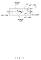
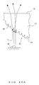
- FIG. 1 is a diagram illustrating the control of the exit directions of light by using a prism plate 111.
- FIG. 2 is a diagram illustrating the prism plate 111 viewed from the II-II direction, and
- FIG. 3 is a diagram illustrating the directional patterns of the light exiting from the prism plate 111.
- the prism plate 111 includes a prism surface 112 on which a prism array having multiple ridgelines 113 is arranged in parallel, and has the function of deflecting the light incident on the prism surface 112 (solid lines and broken lines) to the right and left. For this reason, the prism plate 111 is used for an illumination optical system or the like as an optical element which controls the exit directions of light.
- the light vertically incident on the prism surface 112 deflects only to the right and left of FIG. 3 (tangential directions), and is not directed to the direction of the ridgelines 113.
- the light beam entering from the prism surface 112 deflects from the prism plate 111.
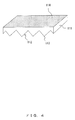
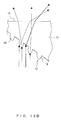
- FIG. 4 is a diagram illustrating an example in which blasting is performed on the exit surface of the prism plate 111 to form minute bumps and dips (diffusing surface).
- FIG. 5 is a diagram illustrating the directional patterns of the light exiting from the prism plate 111 on an exit surface on which blasting is performed, and
- FIG. 6 is a diagram illustrating the prism plate 111 viewed from VI-VI direction.
- the light deflected by the prism plate 111 is diffused on the exit surface, and is partly directed to the direction of the ridgelines 113.
- the illumination light exiting from the prism plate 111 it is possible for the illumination light exiting from the prism plate 111 to be distributed in all the directions while the directivity to the right and left is maintained.
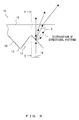
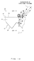
- FIG. 7 is a diagram illustrating the prism plate 111 viewed from the exit surface where the directivity distribution of exiting light is indicated.
- the light exiting from the prism plate 111 indicates ellipse-shaped directivity where the width is longer in the right and left directions. If blasting is performed on the exit surface to achieve a diffusion effect as described above, it is possible to eliminate a dead zone in the exit directions of illumination. Moreover, it is possible to control the directivity of exiting light by altering the blasting intensity.
- Patent Document 1 discloses a technique in which minute convex portions are randomly formed on the exit surface of an emitting light control plate, and the light entering from a plane of incidence is dispersed by the minute convex portion.
- Patent Document 2 discloses a technique in which oblique incident light from a light-guiding plate is converted to the vertical direction by a prism sheet, and then the exiting light is diffused by the minute bumps and dips which are formed on the exit surface.
- the present invention provides a prism plate which gives directivity to the exit directions of incident light and enables control of the illuminance distribution, an illumination optical system of an imaging device, and a forming die of a prism plate.
- the prism plate includes a prism surface on one side of which a prism array in the shape of a triangular pole having multiple ridgelines is formed, and minute bumps and dips formed on the prism surface.
- the present invention provides an illumination optical system of an imaging device for irradiating an object to be captured with light so as to receive and capture light reflected from the object to be captured, where the illumination optical system including a plurality of luminous elements arranged around the imaging device and a ring-shaped prism plate, where in order to irradiate the object to be captured with light emitted from the plurality of luminous elements, a prism surface on a circumference of which a prism array in the shape of a triangular pole having multiple ridgelines in radial directions is formed is arranged on a side of the plurality of luminous elements, and minute bumps and dips are formed on the prism surface.
- the present invention provide a forming die of a prism plate which has a first die and a second die arranged so as to be opposite to each other, and forms a prism plate by heat-softening and pressurizing a forming material arranged between the first die and the second die or forms a prism plate by injecting a forming material between the first die and the second die, where a prism array in the shape of a triangular pole having multiple ridgelines is formed on a forming surface of one of the first die or the second die, and minute bumps and dips are formed on an oblique surface of the prism array at least on a side of the first die and the second die on which the prism array is formed.
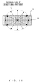
- FIG. 8 is an external perspective view of a prism plate 11 of the present embodiment.
- FIG. 9 is a diagram illustrating directional patterns of the light exiting from the prism plate 11.
- FIG. 10 is a diagram illustrating the prism plate 11 viewed from the X-X direction.
- the prism plate 11 of the present embodiment includes a prism surface 12 on one side of which a prism array in the shape of a triangular pole having multiple ridgelines 13 is formed, and in which minute bumps and dips 14 are formed on the prism surface 12.
- a surface through which light enters is referred to as a prism surface 12, and a side of plane from which light is output on the other side of the prism surface 12 is referred to as an exit surface 15, so that the two sides will be distinguishable.
- the prism surface having a prism array in the shape of a triangular pole may be formed by using well-known forming means or the like.
- the minute bumps and dips 14 may be formed by blasting the prism surface 12.
- the blasting generally refers to the processes in which non-metalic particles or metalic particles such as quartz sand are blown at a high speed to the surface of an object to be processed to roughen the surface, and the use of sandblasting is assumed in the present embodiment.
- the minute bumps and dips 14 are formed on the oblique surface of the prism array in the shape of a triangular pole.
- the minute bumps and dips 14 form diffusing surfaces of light.
- minute bumps and dips 14 refer to a region on which relatively-minute concave portions and convex portions are formed in an array or in a randomly continuous manner due to, for example, sandblasting.
- the convex portions may be shaped in various ways, for example, as a hemisphere, a sphere, (a frustum of) a cone, or (a frustum of) a pyramid.
- the pitch between concave portions and convex portions of the minute bumps and dips 14 or the height (depth) of bumps and dips may be determined in view of the power distribution or the like of light which is emitted from the exit surface 15. Note that the pitch between concave portions and convex portions or the height (depth) of bumps and dips may be influenced by the wavelength of the light being used.
- the multiple ridgelines 13 formed on the prism surface 12 of the prism plate 11 may be parallel with each other, or alternatively, when the prism plate 11 is in a ring shape, a prism array in the shape of a triangular pole having the multiple ridgelines 13 in radial directions may be formed on the circumference (see FIG. 17A described later).
- a method for forming the minute bumps and dips 14 is not limited to sandblasting.
- a method for forming the minute bumps and dips 14 is not limited to sandblasting.
- forming means that uses a forming die or other means may be used.
- the directional pattern of the light exiting from the exit surface 15 by performing blasting on the prism surface 12 through which light enters to form the minute bumps and dips 14.
- the directional patterns of exiting light may be freely controlled by controlling the intensity of blasting, i.e., the depth of the minute bumps and dips 14.
- FIG. 9 is a diagram illustrating directional patterns in which the blasting performed on the prism surface 12 of the prism plate 11 is relatively weak.
- the light incident on the prism surface 12 emitted from an LED 16 is deflected due to refraction on a prism oblique surface of the prism surface 12, and at the same time, is diffused by the minute bumps and dips 14.
- the light is split into all directions, including longitudinal directions of the ridgelines 13.
- an optical axis O which is the center of a light quantity distribution shifts to an angle determined due to the prism oblique surface.
- the directional pattern is retained, and the directional patterns become similar to the directional patterns obtained when blasting is performed on the exit surface 15.
- the minute bumps and dips 14 have shallow bumps and dips when blasting is weak, and thus it is considered that the light exiting from the exit surface 15 has directional patterns in the directions determined due to the prism oblique surface of the prism surface 12.
- FIG. 11 is a diagram illustrating the directional patterns of exiting light viewed from the exit surface 15 when strong blasting has been performed on the prism surface 12.
- FIG. 12A is a diagram schematically illustrating the refraction state of light when strong blasting was performed on the prism surface.
- FIG. 12B is a diagram schematically illustrating the refraction state of light when a period during which blasting is performed on the prism surface is shortened.
- FIG. 12C is a diagram schematically illustrating the refraction state of light when the blast injection pressure (flow velocity) to the prism surface is lowered.
- FIG. 12A is a schematic diagram of the surface of bumps and dips in the case of non-directivity, as will be described later with reference to FIG. 20D .
- each of the minute bumps and dips 14 is deeply formed on the prism surface 12 overall. Assuming that blasting is performed from the bottom of FIG. 12A in a vertical direction (from the bottom of the exit surface 15 in a vertical direction), the surface of each of the respective minute bumps and dips 14 has a wide range of angles from a vertical plane to a horizontal plane.
- each of the respective minute bumps and dips 14 has, for example, a hemisphere shape or a bullet shape (the shape may be controlled by a blast flow velocity, time or the like), and thus normals of the surfaces of the minute bumps and dips 14 are evenly distributed with the center being the vertical direction.
- An incident light beam L emitted from an LED 16 is incident to each of the minute bumps and dips 14, and deflects in accordance with an angle with the normal at that point. Accordingly, the deflection directions of light also widely distribute with the vertical direction (no deflection) of FIG. 12A being the center. For this reason, even though a plane on which light is incident on the prism surface 12 is generally oblique, the deflection direction of an incident light beam is unaffected. As a result, it is considered that the prism plate 11 of FIG. 12A is nondirectional.
- the intensity of blasting may be controlled by choosing the flow velocity or the injection time of the particle injection in blasting. Criteria for the flow velocity or injection time of the particle injection in blasting may vary depending on a particle diameter used in the particle injection, the material of the prism plate 11, or the like.
- FIG. 12B is a schematic diagram illustrating the surface of bumps and dips in cases where the injection time is made short for weak blasting.
- the density of the minute bumps and dips 14 becomes sparse (the density of the minute bumps and dips 14 is half), and half of the oblique portion of the prism surface 12 has no bump or dip. Accordingly, there are prism deflections (at portions having no bump or dip) and diffusions (at portions having bumps and dips) in a mixed manner for an incident light, and thus it is considered that the exiting light has directivity and also diffuses.
- FIG. 12C is a schematic diagram illustrating the surface of bumps and dips in cases where the flow velocity (injection pressure) is made weak for weak blasting.
- the depth of the minute bumps and dips 14 becomes shallow, and normals of the surfaces of minute bumps and dips distribute with a small variation (for example, 30° ⁇ 30°) with an angle of the prism surface 12 being the center.
- the optical axis of diffused light becomes the same as that of a prism deflection (deflection characteristics of the prism surface 12), and it is considered that incident light is diffused with a deflection angle being the center and the diffused light distributes at an angle close to the deflection angle.
- exiting light has directivity and also diffuses in a similar manner to the descriptions of FIG. 12B .
- FIGs. 12A-12C are schematic diagrams just for explanation purposes, and the actual shapes of the surfaces may differ.
- the actual bumps and dips of the prism surface on which sand blasting is performed have a nonuniform amplitude and cycle, and the shapes may not be like hemispheres or bells as illustrated in FIGs. 12A-12C .
- the amplitude of the bumps and dips on a prism surface is generally large, and as described above, the directions of normals on the surface evenly distribute. As a result, an exiting light becomes nondirectional.
- the state of the surface of bumps and dips on a prism surface that is, the surface roughness of a prism surface, may be represented with the parameters defined in JIS-B0601.
- L is a reference length in the x-axis direction.
- the surface roughness of a prism surface may be represented as a parameter defined in JIS-B0601:1994 (10-point average roughness Rz).
- the parameter is a value obtained by selecting the top five values respectively from the height of a peak and the depth of a valley and adding average values together, and what is represented in this parameter is similar to a maximum amplitude.
- the state of the bumps and dips of FIGs. 9 and 11 are represented by using the above-mentioned parameters.
- the amplitude of bumps and dips is small, and the directivity determined due to a prism oblique surface remains.
- the amplitude of bumps and dips is sufficiently large, and thus the directivity due to the exiting light disappears.
- the prism plate 11 includes the prism surface 12 on which a prism array in the shape of a triangular pole having the multiple ridgelines 13 is formed, and on which there are the minute bumps and dips 14 formed on the prism surface 12.
- the minute bumps and dips 14 may provide the directivity to the exit directions of illumination light, and control the illuminance distribution.
- FIGs. 13 and 14 are diagrams illustrating the prism plate 11 according to the present embodiment.
- FIG. 13 is a diagram illustrating the directional patterns of the light exiting from the prism plate 11.
- FIG. 14 is a diagram illustrating the prism plate 11 viewed from XIV-XIV direction.
- the prism surface 12 through which light enters is blasted to form the minute bumps and dips 14, but also the exit surface 15 from which illumination light is emitted is blasted to form minute bumps and dips 14' .
- the light incident on the prism surface 12 is diffused at the minute bumps and dips 14 of the prism surface 12, and is further diffused at the minute bumps and dips 14' of the exit surface 15 before the light is emitted.
- the directivity of the light exiting from the exit surface 15 is dominantly controlled by the intensity of blasting to the prism surface 12 through which the light enters.
- the present embodiment it is possible to more precisely control the directivity by performing blasting not only on the prism surface 12 but also on the exit surface 15.
- a smoother distribution of illumination light may be obtained as the light incident on the prism surface 12 is diffused twice, once on the prism surface 12 through which the light enters and once on the exit surface 15 from which the light exits.
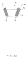
- FIG. 15 is a diagram illustrating a forming metal die 20 of the prism plate 11 according to the present embodiment.
- the case is described in which blasting is performed directly on the prism surface 12 of the prism plate 11 to form the minute bumps and dips 14.
- a method for forming the minute bumps and dips 14 is not limited to the case of the first embodiment.
- the minute bumps and dips 14 may be formed by using forming means.
- the prism plate 11 is formed by forming a plastic material such as acryl. For this reason, as illustrated in FIG. 15 , the prism plate 11 is actually formed by forming minute bumps and dips 25 on a forming metal die 20 and transferring the formed minute bumps and dips 25 onto a forming material 23.
- the forming metal die 20 includes an upper die 21 and a lower die 22 that are arranged opposite to each other.
- the plastic material 23 is arranged between a forming surface 21a of the upper die 21 and a forming surface 22a of the lower die 22. Then, the plastic material 23 is heated up to a specified temperature and is softened. Next, the upper die 21 and the lower die 22 are moved to get relatively closer to each other in order to pressurize the plastic material 23, and thereby the prism plate 11 is formed.
- FIG. 15 is a diagram in which a metal die of the above-described pressure forming method is described, and is applicable to the case of using injection molding in which a forming material is injected in the space surrounded by a metal die.
- a prism array in the shape of a triangular pole having the multiple ridgelines 24 is formed on the forming surface 22a of the lower die 22, and the minute bumps and dips 25 are formed on an oblique surface on which the prism array is formed.
- the minute bumps and dips 25 may be formed, for example, by performing blasting thereon. In so doing, it is possible to form the prism plate 11 by transferring the minute bumps and dips 25 to the forming material 23.
- the minute bumps and dips 25 may be formed on the lower die 22 by means other than blasting as long as the means are capable of micromachining.
- minute bumps and dips 25 are formed on the lower die 22 .
- the configuration is not limited to such cases.
- minute bumps and dips may be formed on the forming surface 21a of the upper die 21. Accordingly, it is possible to form minute bumps and dips on both the prism surface and the exit surface of the prism plate 11 (see the above-described FIG. 13 ).
- a prism array in the shape of a triangular pole having the multiple ridgelines 24 is formed, for example, on the forming surface 22a of the lower die 22, and the minute bumps and dips 25 are formed at least on an oblique surface of the prism array of the lower die 22 on which the prism array is formed. Then, the minute bumps and dips 25 are transferred to the forming material 23. Accordingly, the directivity is achieved in the exit directions of illumination light, and it is possible to obtain the prism plate 11 with a controllable illuminance distribution.
- FIG. 16 is a diagram illustrating a case in which an illumination optical system 10 is applied to an imaging device 30 for reading information.
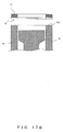
- FIG. 17A is a diagram illustrating the prism plate 11 viewed from the prism surface 12.
- FIG. 17B is a diagram illustrating the positional relationship between the prism surface 12 and a light guide 33. Note that the same reference signs are given to the same or corresponding members as in the first embodiment.
- the illumination optical system 10 of the imaging device 30 is for irradiating an object to be captured 31 with light so as to receive and capture the light reflected from the object to be captured 31 (for example, a palm) by an image sensor 32 which functions as an imaging element.
- the illumination optical system 10 includes LEDs 16 which function as a plurality of luminous elements circularly arranged around the image sensor 32, a ring-shaped light guide (cylindrical body) 33 arranged above the plurality of the LEDs 16, and a ring-shaped prism plate 11 arranged above an exit surface 33a of the light guide 33.
- the light guide 33 is made of, for example, transparent resin (or glass or the like), and guides the light from the plurality of the LEDs 16 upward. Moreover, the light guide 33 irradiates the object to be captured 31 with uniform light via the prism plate 11. Due to the light guide 33, it is possible to guide the light from the LEDs 16 such that the light does not deviate from an optical path. For that purpose, the light guide 33 is ring-shaped so as to conform to the arrangement of the LEDs 16.
- the ring shape refers to an annular shape having a hole in the center, and includes, for example, a circular ring, a rectangular ring, and an ellipstical ring.
- the ring-shaped prism plate 11 is provided with the prism surface 12 in which a prism array in the shape of a triangular pole having multiple ridgelines 13 in radial directions is formed on the circumference in order to irradiate the object to be captured 31 with the light exiting from the exit surface 33a of the light guide 33.
- the multiple ridgelines 13 be formed at regular intervals, but it is not always necessary for the multiple ridgelines 13 to be strictly formed at regular intervals.
- the multiple ridgelines 13 are formed in radial directions towards the center of the ring, but it is not necessary for the multiple ridgelines 13 to be strictly formed towards the center.
- the prism surface 12 is arranged so as to be opposite to the LEDs 16 (the side of the exit surface 33a of the light guide 33). Furthermore, the minute bumps and dips 14 are formed on the prism surface 12 of the ring-shaped prism plate 11 (see FIG. 17A ).
- the minute bumps and dips 14 in the present embodiment are similar to those of the first embodiment or the like.
- the light emitted from the LED 16 is guided by the ring-shaped light guide 33 to the object to be captured 31 that is an object to be read.
- an imaging system having an image sensor 32 and an optical lens 34 is arranged on the inner side of the ring-shaped light guide 33.
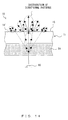
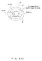
- FIGs. 18A-18D are diagrams illustrating the illumination optical system 10 of the imaging device 30 viewed from the side of the exit surface 15. Moreover, FIGs. 18A-18D are diagrams in which the distributions of the directional patterns of the light exiting from a point (point A) on the prism plate 11 are compared with each other.
- the parameter in the directivity distributions of FIGs. 18A-18D is the blasting intensity (here, the injection time).
- the imaging system comprised of the optical lens 34 and the image sensor 32 is arranged.
- the image sensor 32 is surrounded by the ring-shaped light guide 33 and the ring-shaped prism plate 11 which is arranged over the ring-shaped light guide 33.
- the circularly arranged LEDs 16 are the illumination light source, and illumination light is emitted from the ring-shaped prism plate 11 after passing through the light guide 33.
- FIG. 18A illustrates a case in which blasting is also not performed on the prism surface 12 of the prism plate 11, where the strongest directivity is indicated.
- the light exiting from the point A is directed by the prism plate 11 only in the tangential direction of the ring.
- the illumination is not directed in the radial directions.
- the illuminance distribution becomes doughnut-shaped, where the central part is dark and the peripheral part is bright.
- FIG. 18B illustrates a case in which weak blasting is performed on the prism surface 12
- FIG. 18C illustrates a case in which blasting stronger than that of FIG. 18B is performed on the prism surface 12.
- FIG. 18B and 18C it is illustrated that illumination light exits not only in the tangential direction but also in the radial directions. Accordingly, the illumination reaches the central part of the ring.
- the directivity varies depending on the intensity of blasting, and the directivity is weaker in FIG. 18C where blasting is relatively stronger than the directivity in FIG. 18B . For this reason, the ellipse of FIG. 18C that represents the directivity distribution is more circular than that of FIG. 18B .
- FIG. 18D illustrates a case in which sufficient (strong) blasting is performed on the prism surface 12, and the directivity distribution is even more circular and non-directional.
- the illumination light exiting from the exit surface 15 of the ring-shaped prism plate 11 gathers to the central part of the ring, and thus the intensity of illumination at the central part of the ring becomes high.
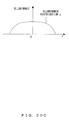
- FIG. 19 is a diagram illustrating the positional relationship between the exit surface 15 of the prism plate 11 and a plane to be evaluated (plane to be irradiated) 17.
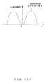
- FIGs. 20A-20D are diagrams in which the illuminance distributions of illumination light on the plane to be evaluated 17 are compared with each other.
- the horizontal axis represents the distance from the optical axis "r”
- the vertical axis represents the intensity (W/m2) of illumination.
- the injection time in FIG. 20A is 0 (no blasting)
- the injection time in FIG. 20B is "0 to 1/2" (weak blasting)
- the injection time in FIG. 20C is "1/2" (slightly strong blasting)
- the injection time in FIG. 20D is "1" (strong blasting).
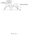
- FIG. 21 is a diagram illustrating all the illuminance distributions of FIGs. 20A-20D .
- FIG. 20A is a diagram corresponding to FIG. 18A .
- FIG. 20A illustrates the illuminance distribution of a case in which no blasting is performed on the prism surface 12 (and on the exit surface 15). In this case, the illumination light does not reach the central part of the ring of the ring-shaped prism plate 11, and the illuminance distribution becomes doughnut-shaped, where the peripheral part of the ring is bright and in a circular shape.
- FIG. 20B is a diagram corresponding to FIG. 18B .
- FIG. 20B illustrates the illuminance distribution of a case in which weak blasting is performed on the prism surface 12.
- the illumination light is also distributed in radial directions due to the diffusion effect of blasting, and thus the illumination reaches the central part of the ring, while the illuminance distribution is still doughnut-shaped where the peripheral part of the ring is bright and in a circular shape.
- FIG. 20C is a diagram corresponding to FIG. 18C .
- FIG. 20C illustrates the illuminance distribution of a case in which blasting stronger than that that of FIG.18B is performed on the prism surface 12. In this case, the distribution of illumination to the central part of the ring is large, and the illuminance distribution is even all over the plane to be evaluated 17.
- FIG. 20D is a diagram corresponding to FIG. 18D .
- FIG. 20D illustrates the illuminance distribution of a case in which sufficient (strong) blasting is performed on the prism surface 12.
- the shape of the illuminance distribution in this case is basically the same as that of the case in which there is no ring-shaped prism plate 11.
- the shape of the illuminance distribution in this case is similar to that of the case in which strong blasting is performed on one side of a transparent flat glass plate.
- the illuminance distribution on the plane to be evaluated 17 changes as illustrated in FIGs. 20A-20D .
- FIG. 21 is a diagram illustrating all the illuminance distributions of FIGs. 20A-20D .
- the illuminance distribution continuously changes from the circular a-curve to the uni-modal d-curve by way of the b-curve and c-curve. Accordingly, it is possible to obtain a desired illuminance distribution of illumination light by altering the intensity of blasting on the prism surface.
- Having a directional pattern in the tangential direction of a ring for the emission of illumination light is effective in shading the surface of an object in the image acquired by an imaging system, or is effective in avoiding shading.
- having a directional pattern in the tangential direction of a ring may give a directional pattern to the light reflected from an object to avoid or emphasize the specularly reflected light.
- the illuminance distribution may be controlled only by the exit directions that are in the radial directions and by the diffusivity without having directivity in the tangential direction of the ring.
- blasting may be performed on both the prism surface 12 and the exit surface 15 of the prism plate 11 (see FIG. 13 ).
- blasting may be performed on both the prism surface 12 and the exit surface 15 of the prism plate 11 (see FIG. 13 ).
- the present embodiment it is possible to control the illuminance distribution while directional patterns are still given to the exit directions of illumination light by having the LEDs 16 arranged around the image sensor 32 and the ring-shaped prism plate 11, where in order to irradiate the image sensor 32 with light emitted from the LEDs 16, the prism surface 12 on a circumference of which a prism array in the shape of a triangular pole having the multiple ridgelines 13 in radial directions is formed is arranged on a side of the LEDs 16, and the minute bumps and dips 14 are formed on the prism surface 12.
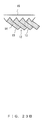
- FIG. 22 is a diagram illustrating the illumination optical system 10 in which the exit surface 33a of the ring-shaped light guide 33 has an oblique surface shaped like a circular truncated cone.
- FIG. 23A is a diagram illustrating an external view of the prism plate 11 shaped like a circular truncated cone
- FIG. 23B is a diagram illustrating a magnified view of a part B of FIG. 23A . Note that the same reference signs are given to the same or corresponding members as in the first embodiment.
- the exit surface 33a of the light guide 33 as well as the prism surface 12 of the prism plate 11 are planes, but they are supposed to be shaped like a circular truncated cone in the present embodiment.
- the size of the light guide 33 depending on the distribution of the light quantity from the LEDs 16, the size of the light guide 33, the size of a plane to be irradiated which is an obj ect to be captured, or the distance to the plane to be irradiated, there are cases in which it is appropriate for the exit surface 15 of the light guide 33 to be an oblique surface shaped like a circular truncated cone.
- the exit surface 15 of the ring-shaped light guide 33 is an oblique surface shaped like a circular truncated cone, and in a similar manner, the ring-shaped prism plate 11 also becomes three-dimensional with an oblique surface shaped like a circular truncated cone.
- the ring-shaped prism plate 11 arranged over the exit surface 33a of the light guide 33 is formed on an oblique surface shaped like a circular truncated cone.
- the prism plate 11 has a prism surface 12 on which a prism array in the shape of a triangular pole having the multiple ridgelines 13 in radial directions is formed on the circumference.
- the prism array consist of, for example, 180 pieces (the pitch of the prism array is "2°") with the vertical angle being 90 degree and the depth being 0.2mm.
- the minute bumps and dips 14 are formed by sandblasting the prism surface 12. Due to the minute bumps and dips 14, a diffusing surface is formed on the prism surface 12.
- the exit surface 33a of the light guide 33 is an inclined surface shaped like a circular truncated cone and the exit surface 15 of the prism plate 11 is an oblique surface of a circular truncated cone, and light is emitted from the exit surface 15 in a diffused manner. Accordingly, it is possible to control the illuminance distribution while directional patterns are still given to the exit directions of illumination light. It is considered that the illuminance distribution of the present embodiment correspond to curves a-d of the illuminance distribution of FIG. 21 .
Abstract
A prism plate is obtained which gives directivity to the exit directions of illumination light and enables control of the illuminance distribution. A prism plate 11 includes a prism surface 12 on which a prism array in the shape of a triangular pole having multiple ridgelines 13 is formed, and in which minute bumps and dips 14 are formed on the prism surface 12.
Description
- The inventions discussed herein are related to a prism plate which can control the exit direction or the like of incident light, an illumination optical system of an imaging device, and a forming die of a prism plate.
-
FIG. 1 is a diagram illustrating the control of the exit directions of light by using aprism plate 111.FIG. 2 is a diagram illustrating theprism plate 111 viewed from the II-II direction, andFIG. 3 is a diagram illustrating the directional patterns of the light exiting from theprism plate 111. - As illustrated in
FIG. 1 , theprism plate 111 includes aprism surface 112 on which a prism array havingmultiple ridgelines 113 is arranged in parallel, and has the function of deflecting the light incident on the prism surface 112 (solid lines and broken lines) to the right and left. For this reason, theprism plate 111 is used for an illumination optical system or the like as an optical element which controls the exit directions of light. - As indicated by the solid lines in
FIGs. 2 and3 , the light vertically incident on theprism surface 112 deflects only to the right and left ofFIG. 3 (tangential directions), and is not directed to the direction of theridgelines 113. - As illustrated in
FIGs. 1-3 , the light beam entering from theprism surface 112 deflects from theprism plate 111. - As indicated by the broken lines in
FIGs. 1 and3 , when light enters three-dimensionally from various directions instead of only vertically, the exit directions vary depending on the incident directions. However, the light is still not directed to the direction of theridgelines 113, and the light indicates strong directivity toward the right and left ofFIG. 3 . - As described above, even if the direction of incident light is controlled, it is not possible to direct the exiting light to the direction of the
ridgelines 113. Accordingly, if a directivity of illumination is desired but a dead zone is unwanted, that is, if it is desired that the illumination light is also distributed in the directions of the ridgelines of a prism array, it is necessary to diffuse the exiting light. -
FIG. 4 is a diagram illustrating an example in which blasting is performed on the exit surface of theprism plate 111 to form minute bumps and dips (diffusing surface).FIG. 5 is a diagram illustrating the directional patterns of the light exiting from theprism plate 111 on an exit surface on which blasting is performed, andFIG. 6 is a diagram illustrating theprism plate 111 viewed from VI-VI direction. - In this case, as illustrated in
FIGs. 5 and6 , the light deflected by theprism plate 111 is diffused on the exit surface, and is partly directed to the direction of theridgelines 113. As a result, it is possible for the illumination light exiting from theprism plate 111 to be distributed in all the directions while the directivity to the right and left is maintained. -
FIG. 7 is a diagram illustrating theprism plate 111 viewed from the exit surface where the directivity distribution of exiting light is indicated. - As is apparent from
FIG. 7 , the light exiting from theprism plate 111 indicates ellipse-shaped directivity where the width is longer in the right and left directions. If blasting is performed on the exit surface to achieve a diffusion effect as described above, it is possible to eliminate a dead zone in the exit directions of illumination. Moreover, it is possible to control the directivity of exiting light by altering the blasting intensity. - In a similar manner, for example,
Patent Document 1 discloses a technique in which minute convex portions are randomly formed on the exit surface of an emitting light control plate, and the light entering from a plane of incidence is dispersed by the minute convex portion. Moreover,Patent Document 2 discloses a technique in which oblique incident light from a light-guiding plate is converted to the vertical direction by a prism sheet, and then the exiting light is diffused by the minute bumps and dips which are formed on the exit surface. - However, in the above-mentioned related art or the techniques disclosed in
Patent Document 1 andPatent Document 2, as is apparent fromFIGs. 5 and6 , the optical axis of exiting light is deflected by a prism, and thus there is a strong directivity. As a result, the directivity distribution of exiting light ofFIG. 7 is always an ellipse where the longer dimension is oriented in the right and left directions, and there has been a limit to the distribution of light to the direction of the ridgelines of a prism, that is, the control of directivity. -
- [Patent Document 1] Japanese Patent No.
4198246 - [Patent Document 2] Japanese Laid-open Patent Publication No.
2007-264639 - The present invention provides a prism plate which gives directivity to the exit directions of incident light and enables control of the illuminance distribution, an illumination optical system of an imaging device, and a forming die of a prism plate. The prism plate includes a prism surface on one side of which a prism array in the shape of a triangular pole having multiple ridgelines is formed, and minute bumps and dips formed on the prism surface.
- The present invention provides an illumination optical system of an imaging device for irradiating an object to be captured with light so as to receive and capture light reflected from the object to be captured, where the illumination optical system including a plurality of luminous elements arranged around the imaging device and a ring-shaped prism plate, where in order to irradiate the object to be captured with light emitted from the plurality of luminous elements, a prism surface on a circumference of which a prism array in the shape of a triangular pole having multiple ridgelines in radial directions is formed is arranged on a side of the plurality of luminous elements, and minute bumps and dips are formed on the prism surface.
- Furthermore, the present invention provide a forming die of a prism plate which has a first die and a second die arranged so as to be opposite to each other, and forms a prism plate by heat-softening and pressurizing a forming material arranged between the first die and the second die or forms a prism plate by injecting a forming material between the first die and the second die, where a prism array in the shape of a triangular pole having multiple ridgelines is formed on a forming surface of one of the first die or the second die, and minute bumps and dips are formed on an oblique surface of the prism array at least on a side of the first die and the second die on which the prism array is formed.
-
-
FIG. 1 is a diagram illustrating the control of the exit directions of light by using a prism plate. -
FIG. 2 is a diagram illustrating the prism plate ofFIG. 1 viewed from the II-II direction. -
FIG. 3 is a diagram illustrating the directional patterns of the light exiting from a prism plate. -
FIG. 4 is a diagram illustrating an example in which blasting is performed on the exit surface of a prism plate to form a diffusing surface. -
FIG. 5 is a diagram illustrating the directional patterns of the light exiting from a prism plate on an exit surface on which blasting is performed. -
FIG. 6 is a diagram illustrating the prism plate ofFIG. 5 viewed from the VI-VI direction. -
FIG. 7 is a diagram illustrating a prism plate viewed from the exit surface where the directivity distribution of exiting light is indicated. -
FIG. 8 is an external perspective view of a prism plate of the present embodiment. -
FIG. 9 is a diagram illustrating directional patterns of the light exiting from a prism plate. -
FIG. 10 is a diagram illustrating the prism plate ofFIG. 9 viewed from the X-X direction. -
FIG. 11 is a diagram illustrating the directional patterns of exiting light viewed from an exit surface when strong blasting has been performed on a prism surface. -
FIG. 12A is a diagram schematically illustrating the refraction state of light when strong blasting was performed on a prism surface. -
FIG. 12B is a diagram schematically illustrating the refraction state of light when a period during which blasting is performed on a prism surface is shortened. -
FIG. 12C is a diagram schematically illustrating the refraction state of light when the blast injection pressure (flow velocity) to a prism surface is lowered. -
FIG. 13 is a diagram illustrating the directional patterns of the light exiting from a prism plate. -
FIG. 14 is a diagram illustrating the prism plate ofFIG. 13 viewed from the XIV-XIV direction. -
FIG. 15 is a diagram illustrating the configuration of a forming metal die of a prism plate. -
FIG. 16 is a diagram illustrating a case in which an illumination optical system is applied to an imaging device for reading information. -
FIG. 17A is a diagram illustrating a prism plate viewed from a prism surface. -
FIG. 17B is a diagram illustrating the positional relationship between a prism surface and a light guide. -
FIG. 18A is a diagram illustrating the distribution of the directional patterns of exiting light for a case in which no blasting is performed. -
FIG. 18B is a diagram illustrating the distribution of the directional patterns of exiting light for a case in which weak blasting is performed. -
FIG. 18C is a diagram illustrating the distribution of the directional patterns of exiting light for a case in which moderately strong blasting is performed. -
FIG. 18D is a diagram illustrating the distribution of the directional patterns of exiting light for a case in which maximum blasting is performed. -
FIG. 19 is a diagram illustrating the positional relationship between the exit surface of a prism plate and a plane to be evaluated. -
FIG. 20A is a diagram illustrating the illuminance distribution of exiting light on a plane to be evaluated for a case in which no blasting is performed. -
FIG. 20B is a diagram illustrating the illuminance distribution of exiting light on a plane to be evaluated for a case in which weak blasting is performed. -
FIG. 20C is a diagrams illustrating the illuminance distribution of exiting light on a plane to be evaluated for a case in which moderately strong blasting is performed. -
FIG. 20D is a diagrams illustrating the illuminance distribution of exiting light on a plane to be evaluated for a case in which maximum blasting is performed. -
FIG. 21 is a diagram illustrating all the illuminance distributions of exiting light on planes to be evaluated for cases in which no blasting, weak blasting, moderately strong blasting, and maximum blasting are performed. -
FIG. 22 is a diagram illustrating an illumination optical system in which the exit surface of a ring-shaped light guide has an oblique surface shaped like a circular truncated cone. -
FIG. 23A is a diagram illustrating an external view of a prism plate shaped like a circular truncated cone. -
FIG. 23B is a diagram illustrating a magnified view of a part B ofFIG. 23A . - Some embodiments of the present invention will be described with reference to the accompanying drawings.
-
FIG. 8 is an external perspective view of aprism plate 11 of the present embodiment.FIG. 9 is a diagram illustrating directional patterns of the light exiting from theprism plate 11.FIG. 10 is a diagram illustrating theprism plate 11 viewed from the X-X direction. - The
prism plate 11 of the present embodiment includes aprism surface 12 on one side of which a prism array in the shape of a triangular pole havingmultiple ridgelines 13 is formed, and in which minute bumps and dips 14 are formed on theprism surface 12. - In the present embodiment, a surface through which light enters is referred to as a
prism surface 12, and a side of plane from which light is output on the other side of theprism surface 12 is referred to as anexit surface 15, so that the two sides will be distinguishable. - The prism surface having a prism array in the shape of a triangular pole may be formed by using well-known forming means or the like. The minute bumps and dips 14 may be formed by blasting the
prism surface 12. The blasting generally refers to the processes in which non-metalic particles or metalic particles such as quartz sand are blown at a high speed to the surface of an object to be processed to roughen the surface, and the use of sandblasting is assumed in the present embodiment. The minute bumps and dips 14 are formed on the oblique surface of the prism array in the shape of a triangular pole. The minute bumps and dips 14 form diffusing surfaces of light. - Here, minute bumps and dips 14 refer to a region on which relatively-minute concave portions and convex portions are formed in an array or in a randomly continuous manner due to, for example, sandblasting. The convex portions may be shaped in various ways, for example, as a hemisphere, a sphere, (a frustum of) a cone, or (a frustum of) a pyramid. The pitch between concave portions and convex portions of the minute bumps and dips 14 or the height (depth) of bumps and dips may be determined in view of the power distribution or the like of light which is emitted from the
exit surface 15. Note that the pitch between concave portions and convex portions or the height (depth) of bumps and dips may be influenced by the wavelength of the light being used. - The
multiple ridgelines 13 formed on theprism surface 12 of theprism plate 11 may be parallel with each other, or alternatively, when theprism plate 11 is in a ring shape, a prism array in the shape of a triangular pole having themultiple ridgelines 13 in radial directions may be formed on the circumference (seeFIG. 17A described later). - When a diffusing surface is formed by forming the minute bumps and dips 14 on the
prism surface 12 with sandblasting, it is possible to obtain a desired power distribution of the exiting light by controlling the injection pressure or injection time of sand to be used. However, the descriptions of sandblasting will be omitted. - In the present embodiment, cases in which the minute bumps and dips 14 are formed with sandblasting have been described, but a method for forming the minute bumps and dips 14 is not limited to sandblasting. For example, as long as the minute bumps and dips 14 can be formed, it is not always necessary to use sandblasting, and forming means that uses a forming die or other means may be used.
- As described above, it is possible to control the directional pattern of the light exiting from the
exit surface 15 by performing blasting on theprism surface 12 through which light enters to form the minute bumps and dips 14. The directional patterns of exiting light may be freely controlled by controlling the intensity of blasting, i.e., the depth of the minute bumps and dips 14. -
FIG. 9 is a diagram illustrating directional patterns in which the blasting performed on theprism surface 12 of theprism plate 11 is relatively weak. InFIGs. 9 and10 , the light incident on theprism surface 12 emitted from anLED 16 is deflected due to refraction on a prism oblique surface of theprism surface 12, and at the same time, is diffused by the minute bumps and dips 14. As diffused on theprism surface 12, the light is split into all directions, including longitudinal directions of theridgelines 13. - In this case, an optical axis O which is the center of a light quantity distribution shifts to an angle determined due to the prism oblique surface. As a whole, the directional pattern is retained, and the directional patterns become similar to the directional patterns obtained when blasting is performed on the
exit surface 15. The minute bumps and dips 14 have shallow bumps and dips when blasting is weak, and thus it is considered that the light exiting from theexit surface 15 has directional patterns in the directions determined due to the prism oblique surface of theprism surface 12. -
FIG. 11 is a diagram illustrating the directional patterns of exiting light viewed from theexit surface 15 when strong blasting has been performed on theprism surface 12.FIG. 12A is a diagram schematically illustrating the refraction state of light when strong blasting was performed on the prism surface.FIG. 12B is a diagram schematically illustrating the refraction state of light when a period during which blasting is performed on the prism surface is shortened.FIG. 12C is a diagram schematically illustrating the refraction state of light when the blast injection pressure (flow velocity) to the prism surface is lowered. - As illustrated in
FIG. 11 , when strong blasting is performed on theprism surface 12 and thereby the minute bumps and dips 14 are formed, the directional patterns of the light exiting from theoutput surface 15 completely disappear, and the distribution becomes nondirectional. -
FIG. 12A is a schematic diagram of the surface of bumps and dips in the case of non-directivity, as will be described later with reference toFIG. 20D . In this case, each of the minute bumps and dips 14 is deeply formed on theprism surface 12 overall. Assuming that blasting is performed from the bottom ofFIG. 12A in a vertical direction (from the bottom of theexit surface 15 in a vertical direction), the surface of each of the respective minute bumps and dips 14 has a wide range of angles from a vertical plane to a horizontal plane. Moreover, each of the respective minute bumps and dips 14 has, for example, a hemisphere shape or a bullet shape (the shape may be controlled by a blast flow velocity, time or the like), and thus normals of the surfaces of the minute bumps and dips 14 are evenly distributed with the center being the vertical direction. - An incident light beam L emitted from an
LED 16 is incident to each of the minute bumps and dips 14, and deflects in accordance with an angle with the normal at that point. Accordingly, the deflection directions of light also widely distribute with the vertical direction (no deflection) ofFIG. 12A being the center. For this reason, even though a plane on which light is incident on theprism surface 12 is generally oblique, the deflection direction of an incident light beam is unaffected. As a result, it is considered that theprism plate 11 ofFIG. 12A is nondirectional. - As described above, when blasting is performed on the
prism surface 12, it is possible to freely control the directional patterns of exiting light by choosing the intensity of blasting. Note that the intensity of blasting may be controlled by choosing the flow velocity or the injection time of the particle injection in blasting. Criteria for the flow velocity or injection time of the particle injection in blasting may vary depending on a particle diameter used in the particle injection, the material of theprism plate 11, or the like. -
FIG. 12B is a schematic diagram illustrating the surface of bumps and dips in cases where the injection time is made short for weak blasting. - In these cases, the density of the minute bumps and dips 14 becomes sparse (the density of the minute bumps and dips 14 is half), and half of the oblique portion of the
prism surface 12 has no bump or dip. Accordingly, there are prism deflections (at portions having no bump or dip) and diffusions (at portions having bumps and dips) in a mixed manner for an incident light, and thus it is considered that the exiting light has directivity and also diffuses. - Further,
FIG. 12C is a schematic diagram illustrating the surface of bumps and dips in cases where the flow velocity (injection pressure) is made weak for weak blasting. - If the injection pressure is made weak, the depth of the minute bumps and dips 14 becomes shallow, and normals of the surfaces of minute bumps and dips distribute with a small variation (for example, 30°±30°) with an angle of the
prism surface 12 being the center. As a result, the optical axis of diffused light becomes the same as that of a prism deflection (deflection characteristics of the prism surface 12), and it is considered that incident light is diffused with a deflection angle being the center and the diffused light distributes at an angle close to the deflection angle. As described above, it is considered that exiting light has directivity and also diffuses in a similar manner to the descriptions ofFIG. 12B . - When glass beads are used as particles to perform blasting, the minute bumps and dips 14 become smooth. This corresponds to weak blasting, and thus exiting light has strong directional patterns of an ellipse shape.
-
FIGs. 12A-12C are schematic diagrams just for explanation purposes, and the actual shapes of the surfaces may differ. The actual bumps and dips of the prism surface on which sand blasting is performed have a nonuniform amplitude and cycle, and the shapes may not be like hemispheres or bells as illustrated inFIGs. 12A-12C . - However, the amplitude of the bumps and dips on a prism surface is generally large, and as described above, the directions of normals on the surface evenly distribute. As a result, an exiting light becomes nondirectional.
- The state of the surface of bumps and dips on a prism surface, that is, the surface roughness of a prism surface, may be represented with the parameters defined in JIS-B0601.
- Arithmetic average roughness Ra(µm) is one of the parameters defined in JIS-B0601, and is represented as

where the state of bumps and dips is indicated by a roughness curve corresponding to a cross-sectional shape, and an average line of the amplitude of a surface is calculated, and taking the direction of the calculated average line as X-axis, f(x) means the deviation from the average line. - Note that "L" is a reference length in the x-axis direction.
- The surface roughness of a prism surface may be represented as a parameter defined in JIS-B0601:1994 (10-point average roughness Rz).
- The parameter is a value obtained by selecting the top five values respectively from the height of a peak and the depth of a valley and adding average values together, and what is represented in this parameter is similar to a maximum amplitude.
- The state of the bumps and dips of
FIGs. 9 and11 are represented by using the above-mentioned parameters. In the case ofFIG. 9 , where weak blasting is performed, the state is represented, for example, as Ra=0.8µm and Rz=5.5µm. In this case, the amplitude of bumps and dips is small, and the directivity determined due to a prism oblique surface remains. - In the case of
FIG. 11 where strong blasting is performed, the surface roughness is represented, for example, as Ra=1.6µm and Rz=16.4µm. In this case, the amplitude of bumps and dips is sufficiently large, and thus the directivity due to the exiting light disappears. - According to the present embodiment, the
prism plate 11 includes theprism surface 12 on which a prism array in the shape of a triangular pole having themultiple ridgelines 13 is formed, and on which there are the minute bumps and dips 14 formed on theprism surface 12. Thus, the minute bumps and dips 14 may provide the directivity to the exit directions of illumination light, and control the illuminance distribution. -
FIGs. 13 and14 are diagrams illustrating theprism plate 11 according to the present embodiment.FIG. 13 is a diagram illustrating the directional patterns of the light exiting from theprism plate 11.FIG. 14 is a diagram illustrating theprism plate 11 viewed from XIV-XIV direction. - Note that the same reference signs are given to the same or corresponding members as in the first embodiment.
- In the present embodiment, not only the
prism surface 12 through which light enters is blasted to form the minute bumps and dips 14, but also theexit surface 15 from which illumination light is emitted is blasted to form minute bumps and dips 14' . The light incident on theprism surface 12 is diffused at the minute bumps and dips 14 of theprism surface 12, and is further diffused at the minute bumps and dips 14' of theexit surface 15 before the light is emitted. - In this case, in a similar manner to the first embodiment, the directivity of the light exiting from the
exit surface 15 is dominantly controlled by the intensity of blasting to theprism surface 12 through which the light enters. - According to the present embodiment, it is possible to more precisely control the directivity by performing blasting not only on the
prism surface 12 but also on theexit surface 15. There is another advantage in which a smoother distribution of illumination light may be obtained as the light incident on theprism surface 12 is diffused twice, once on theprism surface 12 through which the light enters and once on theexit surface 15 from which the light exits. -
FIG. 15 is a diagram illustrating a forming metal die 20 of theprism plate 11 according to the present embodiment. - In the first embodiment, the case is described in which blasting is performed directly on the
prism surface 12 of theprism plate 11 to form the minute bumps and dips 14. However, a method for forming the minute bumps and dips 14 is not limited to the case of the first embodiment. For example, the minute bumps and dips 14 may be formed by using forming means. - Generally, the
prism plate 11 is formed by forming a plastic material such as acryl. For this reason, as illustrated inFIG. 15 , theprism plate 11 is actually formed by forming minute bumps and dips 25 on a forming metal die 20 and transferring the formed minute bumps and dips 25 onto a formingmaterial 23. - Accordingly, the forming metal die 20 includes an upper die 21 and a
lower die 22 that are arranged opposite to each other. Theplastic material 23 is arranged between a formingsurface 21a of the upper die 21 and a formingsurface 22a of thelower die 22. Then, theplastic material 23 is heated up to a specified temperature and is softened. Next, the upper die 21 and thelower die 22 are moved to get relatively closer to each other in order to pressurize theplastic material 23, and thereby theprism plate 11 is formed.FIG. 15 is a diagram in which a metal die of the above-described pressure forming method is described, and is applicable to the case of using injection molding in which a forming material is injected in the space surrounded by a metal die. - In the forming metal die 20, a prism array in the shape of a triangular pole having the
multiple ridgelines 24 is formed on the formingsurface 22a of thelower die 22, and the minute bumps and dips 25 are formed on an oblique surface on which the prism array is formed. The minute bumps and dips 25 may be formed, for example, by performing blasting thereon. In so doing, it is possible to form theprism plate 11 by transferring the minute bumps and dips 25 to the formingmaterial 23. However, the minute bumps and dips 25 may be formed on thelower die 22 by means other than blasting as long as the means are capable of micromachining. - In the present embodiment, cases in which the minute bumps and dips 25 are formed on the
lower die 22 have been described. However, the configuration is not limited to such cases. For example, minute bumps and dips may be formed on the formingsurface 21a of the upper die 21. Accordingly, it is possible to form minute bumps and dips on both the prism surface and the exit surface of the prism plate 11 (see the above-describedFIG. 13 ). - According to the present embodiment, a prism array in the shape of a triangular pole having the
multiple ridgelines 24 is formed, for example, on the formingsurface 22a of thelower die 22, and the minute bumps and dips 25 are formed at least on an oblique surface of the prism array of thelower die 22 on which the prism array is formed. Then, the minute bumps and dips 25 are transferred to the formingmaterial 23. Accordingly, the directivity is achieved in the exit directions of illumination light, and it is possible to obtain theprism plate 11 with a controllable illuminance distribution. -
FIG. 16 is a diagram illustrating a case in which an illuminationoptical system 10 is applied to animaging device 30 for reading information.FIG. 17A is a diagram illustrating theprism plate 11 viewed from theprism surface 12.FIG. 17B is a diagram illustrating the positional relationship between theprism surface 12 and alight guide 33. Note that the same reference signs are given to the same or corresponding members as in the first embodiment. - The illumination
optical system 10 of theimaging device 30 is for irradiating an object to be captured 31 with light so as to receive and capture the light reflected from the object to be captured 31 (for example, a palm) by animage sensor 32 which functions as an imaging element. - The illumination
optical system 10 includesLEDs 16 which function as a plurality of luminous elements circularly arranged around theimage sensor 32, a ring-shaped light guide (cylindrical body) 33 arranged above the plurality of theLEDs 16, and a ring-shapedprism plate 11 arranged above anexit surface 33a of thelight guide 33. - The
light guide 33 is made of, for example, transparent resin (or glass or the like), and guides the light from the plurality of theLEDs 16 upward. Moreover, thelight guide 33 irradiates the object to be captured 31 with uniform light via theprism plate 11. Due to thelight guide 33, it is possible to guide the light from theLEDs 16 such that the light does not deviate from an optical path. For that purpose, thelight guide 33 is ring-shaped so as to conform to the arrangement of theLEDs 16. - Note that the ring shape refers to an annular shape having a hole in the center, and includes, for example, a circular ring, a rectangular ring, and an ellipstical ring.
- As illustrated in
FIG. 17A , the ring-shapedprism plate 11 is provided with theprism surface 12 in which a prism array in the shape of a triangular pole havingmultiple ridgelines 13 in radial directions is formed on the circumference in order to irradiate the object to be captured 31 with the light exiting from theexit surface 33a of thelight guide 33. It is desirable that themultiple ridgelines 13 be formed at regular intervals, but it is not always necessary for themultiple ridgelines 13 to be strictly formed at regular intervals. Moreover, themultiple ridgelines 13 are formed in radial directions towards the center of the ring, but it is not necessary for themultiple ridgelines 13 to be strictly formed towards the center. - As illustrated in
FIG. 17B , theprism surface 12 is arranged so as to be opposite to the LEDs 16 (the side of theexit surface 33a of the light guide 33). Furthermore, the minute bumps and dips 14 are formed on theprism surface 12 of the ring-shaped prism plate 11 (seeFIG. 17A ). - The minute bumps and dips 14 in the present embodiment are similar to those of the first embodiment or the like.
- As illustrated in
FIG. 16 , the light emitted from theLED 16 is guided by the ring-shapedlight guide 33 to the object to be captured 31 that is an object to be read. On the inner side of the ring-shapedlight guide 33, an imaging system having animage sensor 32 and anoptical lens 34 is arranged. -
FIGs. 18A-18D are diagrams illustrating the illuminationoptical system 10 of theimaging device 30 viewed from the side of theexit surface 15. Moreover,FIGs. 18A-18D are diagrams in which the distributions of the directional patterns of the light exiting from a point (point A) on theprism plate 11 are compared with each other. - Note that the parameter in the directivity distributions of
FIGs. 18A-18D is the blasting intensity (here, the injection time). Moreover, in the center of theimaging device 30, the imaging system comprised of theoptical lens 34 and theimage sensor 32 is arranged. - Further, the
image sensor 32 is surrounded by the ring-shapedlight guide 33 and the ring-shapedprism plate 11 which is arranged over the ring-shapedlight guide 33. In this case, the circularly arrangedLEDs 16 are the illumination light source, and illumination light is emitted from the ring-shapedprism plate 11 after passing through thelight guide 33. - In
FIGs. 18A-18D described below, it is assumed that blasting is not performed on theexit surface 15 of theprism plate 11. -
FIG. 18A illustrates a case in which blasting is also not performed on theprism surface 12 of theprism plate 11, where the strongest directivity is indicated. - In
FIG. 18A , the light exiting from the point A is directed by theprism plate 11 only in the tangential direction of the ring. In this case, even if the illumination from the entirety of theexit surface 15 of the ring-shapedprism plate 11 is added up, the illumination is not directed in the radial directions. As a result, the illuminance distribution becomes doughnut-shaped, where the central part is dark and the peripheral part is bright. -
FIG. 18B illustrates a case in which weak blasting is performed on theprism surface 12, andFIG. 18C illustrates a case in which blasting stronger than that ofFIG. 18B is performed on theprism surface 12. - In the cases of both
FIGs. 18B and18C , it is illustrated that illumination light exits not only in the tangential direction but also in the radial directions. Accordingly, the illumination reaches the central part of the ring. The directivity varies depending on the intensity of blasting, and the directivity is weaker inFIG. 18C where blasting is relatively stronger than the directivity inFIG. 18B . For this reason, the ellipse ofFIG. 18C that represents the directivity distribution is more circular than that ofFIG. 18B . - When the bump-and-dip states of the respective prism surfaces of
FIGs. 18B and18C are represented with surface roughness parameters as described above, in the case ofFIG. 18B where blasting is weak, the state is represented as Ra=0.8µm and Rz=5.5µm. In the case ofFIG. 18C where blasting is only moderately strong, the state is represented as Ra=1.3µm and Rz=12.8µm. In other words, the amplitude of bumps and dips is greater inFIG. 18C . - Further,
FIG. 18D illustrates a case in which sufficient (strong) blasting is performed on theprism surface 12, and the directivity distribution is even more circular and non-directional. - In the case of
FIG. 18D , the bump-and-dip state of the prism surface is represented, for example, as Ra=1. 6µm and Rz=16.4µm. As blasting is sufficiently strong, the bump-and-dip state has a sufficiently large amplitude. - In this case, the illumination light exiting from the
exit surface 15 of the ring-shapedprism plate 11 gathers to the central part of the ring, and thus the intensity of illumination at the central part of the ring becomes high. -
FIG. 19 is a diagram illustrating the positional relationship between theexit surface 15 of theprism plate 11 and a plane to be evaluated (plane to be irradiated) 17. - In
FIG. 19 , the plane to be evaluated (plane to be irradiated) 17 is represented as "z=z1" , where the optical axis of an imaging system is z-axis, and theexit surface 15 of theprism plate 11 is represented as "z=0". -
FIGs. 20A-20D are diagrams in which the illuminance distributions of illumination light on the plane to be evaluated 17 are compared with each other. InFIGs. 20A-20D , the horizontal axis represents the distance from the optical axis "r", and the vertical axis represents the intensity (W/m2) of illumination. - In
FIGs. 20A-20D , when the intensity of blasting is indicated with an injection time, the injection time inFIG. 20A is 0 (no blasting), the injection time inFIG. 20B is "0 to 1/2" (weak blasting), the injection time inFIG. 20C is "1/2" (slightly strong blasting), and the injection time inFIG. 20D is "1" (strong blasting). - Further,
FIG. 21 is a diagram illustrating all the illuminance distributions ofFIGs. 20A-20D . -
FIG. 20A is a diagram corresponding toFIG. 18A .FIG. 20A illustrates the illuminance distribution of a case in which no blasting is performed on the prism surface 12 (and on the exit surface 15). In this case, the illumination light does not reach the central part of the ring of the ring-shapedprism plate 11, and the illuminance distribution becomes doughnut-shaped, where the peripheral part of the ring is bright and in a circular shape. -
FIG. 20B is a diagram corresponding toFIG. 18B .FIG. 20B illustrates the illuminance distribution of a case in which weak blasting is performed on theprism surface 12. In this case, the illumination light is also distributed in radial directions due to the diffusion effect of blasting, and thus the illumination reaches the central part of the ring, while the illuminance distribution is still doughnut-shaped where the peripheral part of the ring is bright and in a circular shape. -
FIG. 20C is a diagram corresponding toFIG. 18C .FIG. 20C illustrates the illuminance distribution of a case in which blasting stronger than that that ofFIG.18B is performed on theprism surface 12. In this case, the distribution of illumination to the central part of the ring is large, and the illuminance distribution is even all over the plane to be evaluated 17. -
FIG. 20D is a diagram corresponding toFIG. 18D .FIG. 20D illustrates the illuminance distribution of a case in which sufficient (strong) blasting is performed on theprism surface 12. In this case, the directivity of exiting light to the tangential direction of a ring disappears, and due to the concentration of the illumination light towards the central part of the ring, the illuminance distribution becomes uni-modal (shaped like a single mountain). The shape of the illuminance distribution in this case is basically the same as that of the case in which there is no ring-shapedprism plate 11. In other words, the shape of the illuminance distribution in this case is similar to that of the case in which strong blasting is performed on one side of a transparent flat glass plate. - As described above, as the intensity of blasting on the
prism surface 12 changes, the illuminance distribution on the plane to be evaluated 17 changes as illustrated inFIGs. 20A-20D . -
FIG. 21 is a diagram illustrating all the illuminance distributions ofFIGs. 20A-20D . - As illustrated in
FIG. 21 , depending on the intensity of blasting, the illuminance distribution continuously changes from the circular a-curve to the uni-modal d-curve by way of the b-curve and c-curve. Accordingly, it is possible to obtain a desired illuminance distribution of illumination light by altering the intensity of blasting on the prism surface. - Having a directional pattern in the tangential direction of a ring for the emission of illumination light is effective in shading the surface of an object in the image acquired by an imaging system, or is effective in avoiding shading.
- Moreover, having a directional pattern in the tangential direction of a ring may give a directional pattern to the light reflected from an object to avoid or emphasize the specularly reflected light. On the other hand, it is possible to control the illuminance distribution without depending on the
prism plate 11. For example, the illuminance distribution may be controlled only by the exit directions that are in the radial directions and by the diffusivity without having directivity in the tangential direction of the ring. - In the present embodiment, cases in which blasting is not performed on the
exit surface 15 of theprism plate 11 have been described. However, the configuration is not limited to such cases. For example, blasting may be performed on both theprism surface 12 and theexit surface 15 of the prism plate 11 (seeFIG. 13 ). In this case, compared with the case in which blasting is performed only on theprism surface 12, it is possible to more extensively control the directional pattern of illumination light in the exit directions and the illuminance distribution. - According to the present embodiment, it is possible to control the illuminance distribution while directional patterns are still given to the exit directions of illumination light by having the
LEDs 16 arranged around theimage sensor 32 and the ring-shapedprism plate 11, where in order to irradiate theimage sensor 32 with light emitted from theLEDs 16, theprism surface 12 on a circumference of which a prism array in the shape of a triangular pole having themultiple ridgelines 13 in radial directions is formed is arranged on a side of theLEDs 16, and the minute bumps and dips 14 are formed on theprism surface 12. -
FIG. 22 is a diagram illustrating the illuminationoptical system 10 in which theexit surface 33a of the ring-shapedlight guide 33 has an oblique surface shaped like a circular truncated cone.FIG. 23A is a diagram illustrating an external view of theprism plate 11 shaped like a circular truncated cone, andFIG. 23B is a diagram illustrating a magnified view of a part B ofFIG. 23A . Note that the same reference signs are given to the same or corresponding members as in the first embodiment. - In the first to fourth embodiments, it was supposed that the
exit surface 33a of thelight guide 33 as well as theprism surface 12 of theprism plate 11 are planes, but they are supposed to be shaped like a circular truncated cone in the present embodiment. - In other words, depending on the distribution of the light quantity from the
LEDs 16, the size of thelight guide 33, the size of a plane to be irradiated which is an obj ect to be captured, or the distance to the plane to be irradiated, there are cases in which it is appropriate for theexit surface 15 of thelight guide 33 to be an oblique surface shaped like a circular truncated cone. - In such cases, as illustrated in
FIG. 22 , theexit surface 15 of the ring-shapedlight guide 33 is an oblique surface shaped like a circular truncated cone, and in a similar manner, the ring-shapedprism plate 11 also becomes three-dimensional with an oblique surface shaped like a circular truncated cone. - In
FIG. 23A , the ring-shapedprism plate 11 arranged over theexit surface 33a of thelight guide 33 is formed on an oblique surface shaped like a circular truncated cone. In -
FIG. 23B , in a similar manner as the fourth embodiment, theprism plate 11 has aprism surface 12 on which a prism array in the shape of a triangular pole having themultiple ridgelines 13 in radial directions is formed on the circumference. The prism array consist of, for example, 180 pieces (the pitch of the prism array is "2°") with the vertical angle being 90 degree and the depth being 0.2mm. - Further, as illustrated in
FIG. 23B , the minute bumps and dips 14 are formed by sandblasting theprism surface 12. Due to the minute bumps and dips 14, a diffusing surface is formed on theprism surface 12. - In the present embodiment, cases in which blasting is performed on the
prism surface 12 of theprism plate 11 to form the minute bumps and dips 14 have been described. However, the configuration is not limited to such cases. For example, it is possible to more extensively control the directional pattern of illumination light by blasting both theprism surface 12 and the exit surface 15 (seeFIG. 13 ). - According to the present embodiment, the
exit surface 33a of thelight guide 33 is an inclined surface shaped like a circular truncated cone and theexit surface 15 of theprism plate 11 is an oblique surface of a circular truncated cone, and light is emitted from theexit surface 15 in a diffused manner. Accordingly, it is possible to control the illuminance distribution while directional patterns are still given to the exit directions of illumination light. It is considered that the illuminance distribution of the present embodiment correspond to curves a-d of the illuminance distribution ofFIG. 21 . -
- 1. A prism plate comprising:
- a prism surface on one side of which a prism array in a shape of a triangular pole having multiple ridgelines is formed; and
- minute bumps and dips formed on the prism surface.
- 2. The prism plate according to
statement 1, wherein
the minute bumps and dips have a depth variable depending on a directional pattern of light which is incident to the prism surface and is then emitted from an exit surface on an opposite side of the prism surface. - 3. The prism plate according to
statement
the minute bumps and dips are formed by performing a blasting process thereon. - 4. The prism plate according to
statement 1, wherein
the minute bumps and dips are formed on both the prism surface and the exit surface. - 5. The prism plate according to
statement 1, wherein
the prism surface is formed on an oblique surface in a shape of a circular truncated cone. - 6. An illumination optical system of an imaging device for irradiating an object to be captured with light so as to receive and capture light reflected from the object to be captured by an image element, the illumination optical system comprising:
- a plurality of luminous elements arranged around the imaging element; and
- a ring-shaped prism plate, where in order to irradiate the object to be captured with light emitted from the plurality of luminous elements, a prism surface on a circumference of which a prism array in a shape of a triangular pole having multiple ridgelines in radial directions is formed is arranged on a side of the plurality of luminous elements, and minute bumps and dips are formed on the prism surface.
- 7. The illumination optical system according to
statement 6, wherein
the minute bumps and dips have a depth variable depending on a directional pattern of light which is incident to the prism surface and is then emitted from an exit surface on an opposite side of the prism surface. - 8. The illumination optical system according to
statement
the minute bumps and dips are formed by performing a blasting process thereon. - 9. The illumination optical system according to
statement 6, wherein
the minute bumps and dips are formed on both the prism surface and the exit surface. - 10. The illumination optical system according to
statement 6, wherein
the prism surface is formed on an oblique surface in a shape of a circular truncated cone. - 11. A forming die of a prism plate having a first die and a second die arranged so as to be opposite to each other, and forming a prism plate by heat-softening and pressurizing a forming material arranged between the first die and the second die or forming a prism plate by injecting a forming material into a space surrounded by the first die and the second die,
wherein:- on a forming surface of one of the first die or the second die, a prism array in a shape of a triangular pole having multiple ridgelines is formed; and
- on an oblique surface of the prism array at least on a side of the first die and the second die on which the prism array is formed, minute bumps and dips are formed.
- 12. The forming die according to
statement 11, wherein the minute bumps and dips are formed by performing a blasting process thereon.
Claims (4)
- An illumination optical system of an imaging device for irradiating an object to be captured with light so as to receive and capture light reflected from the object to be captured by an image element, the illumination optical system comprising:a plurality of luminous elements arranged around the imaging element; anda ring-shaped prism plate, where in order to irradiate the object to be captured with light emitted from the plurality of luminous elements, a prism surface on a circumference of which a prism array in a shape of a triangular pole having multiple ridgelines along radial directions is formed is arranged on a side of the plurality of luminous elements, and minute bumps and dips are formed on the prism surface.
- The illumination optical system according to claim 1, wherein
the minute bumps and dips are formed by performing a blasting process thereon. - The illumination optical system according to claim 1, wherein
the minute bumps and dips are formed on both the prism surface and the exit surface. - The illumination optical system according to claim 1, wherein
the prism surface is formed on an oblique surface in a shape of a circular truncated cone.
Applications Claiming Priority (2)
| Application Number | Priority Date | Filing Date | Title |
|---|---|---|---|
| JP2009251481 | 2009-10-30 | ||
| EP10826242A EP2495588A4 (en) | 2009-10-30 | 2010-01-15 | Prism plate, illumination optical system of imaging device, and mold for prism plate |
Related Parent Applications (1)
| Application Number | Title | Priority Date | Filing Date |
|---|---|---|---|
| EP10826242A Division EP2495588A4 (en) | 2009-10-30 | 2010-01-15 | Prism plate, illumination optical system of imaging device, and mold for prism plate |
Publications (1)
| Publication Number | Publication Date |
|---|---|
| EP3026470A1 true EP3026470A1 (en) | 2016-06-01 |
Family
ID=43921540
Family Applications (2)
| Application Number | Title | Priority Date | Filing Date |
|---|---|---|---|
| EP10826242A Withdrawn EP2495588A4 (en) | 2009-10-30 | 2010-01-15 | Prism plate, illumination optical system of imaging device, and mold for prism plate |
| EP15199275.7A Withdrawn EP3026470A1 (en) | 2009-10-30 | 2010-01-15 | Prism plate, illumination optical system of imaging device, and forming die of prism plate |
Family Applications Before (1)
| Application Number | Title | Priority Date | Filing Date |
|---|---|---|---|
| EP10826242A Withdrawn EP2495588A4 (en) | 2009-10-30 | 2010-01-15 | Prism plate, illumination optical system of imaging device, and mold for prism plate |
Country Status (6)
| Country | Link |
|---|---|
| US (1) | US20130128571A1 (en) |
| EP (2) | EP2495588A4 (en) |
| JP (1) | JP5337256B2 (en) |
| KR (1) | KR101377846B1 (en) |
| CN (1) | CN102576102B (en) |
| WO (1) | WO2011052101A1 (en) |
Families Citing this family (7)
| Publication number | Priority date | Publication date | Assignee | Title |
|---|---|---|---|---|
| JP2015164093A (en) * | 2012-06-18 | 2015-09-10 | コニカミノルタ株式会社 | Luminaire |
| CN105867057B (en) * | 2012-10-17 | 2018-03-20 | 深圳市光峰光电技术有限公司 | Light-source system, Wavelength converter and relevant projecting system |
| CN103943753A (en) * | 2014-03-06 | 2014-07-23 | 京东方科技集团股份有限公司 | Light emitting diode light source, manufacturing method of light emitting diode light source, backlight source and display device |
| EP3149395A1 (en) * | 2014-05-30 | 2017-04-05 | Osram Sylvania Inc. | Light control films and lighting devices including same |
| EP3757673B1 (en) * | 2018-02-20 | 2023-10-18 | Fujitsu Frontech Limited | Illumination optical system for imaging device |
| AT520942B1 (en) * | 2018-03-15 | 2019-09-15 | Werner Faerber | Process for producing a light-guiding film and film produced therewith |
| US11531232B2 (en) * | 2020-01-24 | 2022-12-20 | Brightview Technologies, Inc. | Optical film for back light unit and back light unit including same |
Citations (9)
| Publication number | Priority date | Publication date | Assignee | Title |
|---|---|---|---|---|
| GB2094018A (en) * | 1981-02-27 | 1982-09-08 | Ju Chin Lee | Filter for cameras |
| JPH09223184A (en) * | 1996-02-19 | 1997-08-26 | Asahi Optical Co Ltd | Illumination device for picture read |
| WO2002057816A1 (en) * | 2001-01-18 | 2002-07-25 | Man-Suk Kim | Prism diffuser for diffracting and spreading light |
| JP2004327051A (en) * | 2003-04-21 | 2004-11-18 | Nikkei Seisakusho:Kk | Prism for display lamp and display lamp |
| US20070014466A1 (en) * | 2005-07-08 | 2007-01-18 | Leo Baldwin | Achieving convergent light rays emitted by planar array of light sources |
| JP2007264639A (en) | 2007-03-30 | 2007-10-11 | Omron Corp | Diffusion plate and surface light source device |
| EP1857873A2 (en) * | 2006-05-16 | 2007-11-21 | Sick Ag | Camera illumination unit |
| WO2008117993A1 (en) * | 2007-03-28 | 2008-10-02 | Cheil Industries Inc. | Optical prism sheet having a certain roughness thereon |
| JP4198246B2 (en) | 1998-11-16 | 2008-12-17 | 株式会社クラレ | Surface light source element |
Family Cites Families (10)
| Publication number | Priority date | Publication date | Assignee | Title |
|---|---|---|---|---|
| JP2562265B2 (en) * | 1992-11-11 | 1996-12-11 | 積水化学工業株式会社 | Light control sheet |
| JP3588180B2 (en) * | 1995-12-28 | 2004-11-10 | 株式会社エンプラス | Light control member and side light type surface light source device |
| US6280063B1 (en) * | 1997-05-09 | 2001-08-28 | 3M Innovative Properties Company | Brightness enhancement article |
| JP2005258011A (en) | 2004-03-11 | 2005-09-22 | Canon Inc | Illuminator and photographing apparatus |
| JP4677256B2 (en) * | 2005-03-17 | 2011-04-27 | キヤノン株式会社 | Light emitting device |
| TW200739138A (en) * | 2006-03-17 | 2007-10-16 | Mitsubishi Rayon Co | Prism sheet, planar light source device and method for manufacturing the prism sheet |
| US20080151375A1 (en) * | 2006-12-26 | 2008-06-26 | Ching-Bin Lin | Light guide means as dually effected by light concentrating and light diffusing |
| JP2008242002A (en) * | 2007-03-27 | 2008-10-09 | Asahi Kasei Chemicals Corp | Diffusion plate with prism |
| KR100864321B1 (en) * | 2007-06-19 | 2008-10-20 | 제일모직주식회사 | Diffuser prism sheet comprising amorphous light diffuser on the valley of prism and lcd back light unit thereby |
| CN101349772B (en) * | 2007-07-20 | 2011-06-29 | 鸿富锦精密工业(深圳)有限公司 | Backlight module unit and optical plate thereof |
-
2010
- 2010-01-15 WO PCT/JP2010/000211 patent/WO2011052101A1/en active Application Filing
- 2010-01-15 KR KR1020127010169A patent/KR101377846B1/en not_active IP Right Cessation
- 2010-01-15 CN CN201080047798.5A patent/CN102576102B/en not_active Expired - Fee Related
- 2010-01-15 JP JP2011538211A patent/JP5337256B2/en not_active Expired - Fee Related
- 2010-01-15 EP EP10826242A patent/EP2495588A4/en not_active Withdrawn
- 2010-01-15 EP EP15199275.7A patent/EP3026470A1/en not_active Withdrawn
-
2012
- 2012-03-30 US US13/499,393 patent/US20130128571A1/en not_active Abandoned
Patent Citations (9)
| Publication number | Priority date | Publication date | Assignee | Title |
|---|---|---|---|---|
| GB2094018A (en) * | 1981-02-27 | 1982-09-08 | Ju Chin Lee | Filter for cameras |
| JPH09223184A (en) * | 1996-02-19 | 1997-08-26 | Asahi Optical Co Ltd | Illumination device for picture read |
| JP4198246B2 (en) | 1998-11-16 | 2008-12-17 | 株式会社クラレ | Surface light source element |
| WO2002057816A1 (en) * | 2001-01-18 | 2002-07-25 | Man-Suk Kim | Prism diffuser for diffracting and spreading light |
| JP2004327051A (en) * | 2003-04-21 | 2004-11-18 | Nikkei Seisakusho:Kk | Prism for display lamp and display lamp |
| US20070014466A1 (en) * | 2005-07-08 | 2007-01-18 | Leo Baldwin | Achieving convergent light rays emitted by planar array of light sources |
| EP1857873A2 (en) * | 2006-05-16 | 2007-11-21 | Sick Ag | Camera illumination unit |
| WO2008117993A1 (en) * | 2007-03-28 | 2008-10-02 | Cheil Industries Inc. | Optical prism sheet having a certain roughness thereon |
| JP2007264639A (en) | 2007-03-30 | 2007-10-11 | Omron Corp | Diffusion plate and surface light source device |
Also Published As
| Publication number | Publication date |
|---|---|
| CN102576102B (en) | 2014-12-31 |
| WO2011052101A1 (en) | 2011-05-05 |
| EP2495588A1 (en) | 2012-09-05 |
| KR101377846B1 (en) | 2014-03-25 |
| JPWO2011052101A1 (en) | 2013-03-14 |
| US20130128571A1 (en) | 2013-05-23 |
| JP5337256B2 (en) | 2013-11-06 |
| EP2495588A4 (en) | 2013-03-27 |
| KR20120056882A (en) | 2012-06-04 |
| CN102576102A (en) | 2012-07-11 |
Similar Documents
| Publication | Publication Date | Title |
|---|---|---|
| EP3026470A1 (en) | Prism plate, illumination optical system of imaging device, and forming die of prism plate | |
| US9347643B2 (en) | Light flux controlling apparatus | |
| US7431492B2 (en) | Light control member, surface light source device and display | |
| KR101297897B1 (en) | Illumination optical system of image capturing device | |
| TWI296694B (en) | ||
| US8727591B2 (en) | Light emitting device and optical element | |
| KR101960131B1 (en) | Optical element | |
| US9068721B2 (en) | Illumination optical system for image pickup apparatus | |
| WO2017017869A1 (en) | Line illumination display device and light-guiding body | |
| US7167322B2 (en) | Beam shaping apparatus | |
| CN112965161B (en) | Light guide plate and dot arrangement method thereof | |
| CN105739103A (en) | Method and apparatus for converting diverging light emitted by laser chip into uniform scattering lines | |
| CN106569360A (en) | Light guide sheet, backlight apparatus and liquid crystal display apparatus | |
| JP2010027573A (en) | Light guide plate, light emitting device, and light guiding method | |
| CN102644899B (en) | Design method of light-emitting diode (LED) illuminating lens | |
| CN209928053U (en) | Light emitting structure and lighting system | |
| US20170045668A1 (en) | Light extracting element having serpentine shape, light redirecting element having serpentine shape, and lighting assembly including the same | |
| JP5893916B2 (en) | LIGHTING DEVICE AND METHOD FOR PRODUCING LIGHT DISTRIBUTION CONTROL MEMBER EQUIPPED IN THE LIGHTING DEVICE | |
| KR101463414B1 (en) | Lighting emitting optical device | |
| CN216527266U (en) | Annular even light structure, luminous module and palm vein collection system | |
| KR101219097B1 (en) | Optical sheet, method for manufacturing the same, backlight unit and display device comprising the same | |
| JP2011192484A (en) | Light guide plate and lighting system with the same | |
| KR101824688B1 (en) | Diffuser cover for led and light apparatus including the same | |
| TWI565980B (en) | Light guide plate | |
| KR200413139Y1 (en) | Lens assembly to evenly distribute projected light beams |
Legal Events
| Date | Code | Title | Description |
|---|---|---|---|
| PUAI | Public reference made under article 153(3) epc to a published international application that has entered the european phase |
Free format text: ORIGINAL CODE: 0009012 |
|
| AC | Divisional application: reference to earlier application |
Ref document number: 2495588 Country of ref document: EP Kind code of ref document: P |
|
| AK | Designated contracting states |
Kind code of ref document: A1 Designated state(s): AT BE BG CH CY CZ DE DK EE ES FI FR GB GR HR HU IE IS IT LI LT LU LV MC MK MT NL NO PL PT RO SE SI SK SM TR |
|
| 18D | Application deemed to be withdrawn |
Effective date: 20161202 |
|
| STAA | Information on the status of an ep patent application or granted ep patent |
Free format text: STATUS: THE APPLICATION IS DEEMED TO BE WITHDRAWN |